EP1876309A1 - Block assembly for buildings and relevant manufacturing method - Google Patents
Block assembly for buildings and relevant manufacturing method Download PDFInfo
- Publication number
- EP1876309A1 EP1876309A1 EP06425466A EP06425466A EP1876309A1 EP 1876309 A1 EP1876309 A1 EP 1876309A1 EP 06425466 A EP06425466 A EP 06425466A EP 06425466 A EP06425466 A EP 06425466A EP 1876309 A1 EP1876309 A1 EP 1876309A1
- Authority
- EP
- European Patent Office
- Prior art keywords
- seats
- block assembly
- connecting elements
- block
- insulating panel
- Prior art date
- Legal status (The legal status is an assumption and is not a legal conclusion. Google has not performed a legal analysis and makes no representation as to the accuracy of the status listed.)
- Granted
Links
Images


Classifications
-
- B—PERFORMING OPERATIONS; TRANSPORTING
- B28—WORKING CEMENT, CLAY, OR STONE
- B28B—SHAPING CLAY OR OTHER CERAMIC COMPOSITIONS; SHAPING SLAG; SHAPING MIXTURES CONTAINING CEMENTITIOUS MATERIAL, e.g. PLASTER
- B28B11/00—Apparatus or processes for treating or working the shaped or preshaped articles
- B28B11/04—Apparatus or processes for treating or working the shaped or preshaped articles for coating or applying engobing layers
- B28B11/042—Apparatus or processes for treating or working the shaped or preshaped articles for coating or applying engobing layers with insulating material
-
- B—PERFORMING OPERATIONS; TRANSPORTING
- B28—WORKING CEMENT, CLAY, OR STONE
- B28B—SHAPING CLAY OR OTHER CERAMIC COMPOSITIONS; SHAPING SLAG; SHAPING MIXTURES CONTAINING CEMENTITIOUS MATERIAL, e.g. PLASTER
- B28B1/00—Producing shaped prefabricated articles from the material
- B28B1/002—Producing shaped prefabricated articles from the material assembled from preformed elements
-
- E—FIXED CONSTRUCTIONS
- E04—BUILDING
- E04B—GENERAL BUILDING CONSTRUCTIONS; WALLS, e.g. PARTITIONS; ROOFS; FLOORS; CEILINGS; INSULATION OR OTHER PROTECTION OF BUILDINGS
- E04B2/00—Walls, e.g. partitions, for buildings; Wall construction with regard to insulation; Connections specially adapted to walls
- E04B2/02—Walls, e.g. partitions, for buildings; Wall construction with regard to insulation; Connections specially adapted to walls built-up from layers of building elements
- E04B2/28—Walls having cavities between, but not in, the elements; Walls of elements each consisting of two or more parts kept in distance by means of spacers, all parts being solid
- E04B2/30—Walls having cavities between, but not in, the elements; Walls of elements each consisting of two or more parts kept in distance by means of spacers, all parts being solid using elements having specially designed means for stabilising the position; Spacers for cavity walls
-
- E—FIXED CONSTRUCTIONS
- E04—BUILDING
- E04C—STRUCTURAL ELEMENTS; BUILDING MATERIALS
- E04C1/00—Building elements of block or other shape for the construction of parts of buildings
- E04C1/40—Building elements of block or other shape for the construction of parts of buildings built-up from parts of different materials, e.g. composed of layers of different materials or stones with filling material or with insulating inserts
- E04C1/41—Building elements of block or other shape for the construction of parts of buildings built-up from parts of different materials, e.g. composed of layers of different materials or stones with filling material or with insulating inserts composed of insulating material and load-bearing concrete, stone or stone-like material
Definitions
- the present invention relates to building materials, and in particular to a block assembly that may also include an insulating panel, as well as to a relevant manufacturing method.
- said block assembly including an insulating panel, disclosed in the European patent EP 1085137 .
- said block assembly is made up of two clay blocks with an insulating panel therebetween, the latter also acting as a mechanical connector between the two blocks.
- the insulating panel is provided on each face with at least one coupling element suitable to engage a corresponding seat formed in one of the blocks, the at least two coupling elements being furthermore mutually joined and fastened to the insulating panel through a fastening element.
- this type of block assembly is sensitive to the thickness tolerances of the insulating panel since the latter is part of the coupling structure between the two blocks. In other words, if the insulating panel is too thick it is difficult where not impossible to fasten the clips thereon and to lock the clips into the corresponding seats of the two blocks; on the contrary, if the panel is too thin the clips will lack proper support and the connection between the two blocks will not be sufficiently rigid to be able to handle the block assembly conveniently.
- the object of the present invention is to provide a block assembly, and a relevant manufacturing method, which overcomes said drawbacks.
- This object is achieved by means of a block assembly made up of two clay blocks and at least two shaped plate-like connecting elements suitable to be introduced and glued into corresponding seats formed in the two blocks.
- a relevant manufacturing method includes only the pre-arrangement of the blocks and of the connecting elements, the introduction of the latter in the corresponding seats formed in the blocks and their gluing in said seats.
- a first great advantage of the present block assembly and of the relevant manufacturing method is a huge saving, achieved by dramatically reducing both the number of components and the assembling steps. This results also in a simplification of the assembling machinery and a significant increase in the manufacturing rate.
- a second important advantage of this block assembly stems from the fact that the insulating panel is not part of the coupling structure between the two blocks. This means that the block assembly can be made even without said insulating panel, which is not possible with the prior art method, and in any case the thickness tolerances of the insulating panel do no affect the manufacturing of the block assembly.
- a further advantage of said block assembly is the possibility of arranging even more than one insulating panel between the two blocks, each panel having different characteristics.
- a first panel for thermal insulation and a second panel for acoustic insulation will be combined and arranged slightly staggered to obtain an abutment that guarantees a thermal/acoustic insulation enhanced with respect to a conventional flat panel.
- a block assembly for buildings conventionally includes a first block B and a second block B' and, preferably, an insulating panel P therebetween.
- the sides of blocks B, B' facing panel P have at corresponding positions a pair of vertical coupling seats S, S' extending along the full height of the block assembly.
- the novel aspect of the present invention is provided by the plate-like connecting elements C as well as, preferably, by the shape of seats S, S' that are simple rectangular recesses.
- a connecting element C has an elongated plate-like structure with a central wide portion W and two narrow end portions N.
- This shape of the connecting element C is devised so that the central wide portion W is wider than seats S, S' and therefore acts as a spacer between blocks B, B', whereas the end portions N are sized to enter with a minimum play seats S, S' where they are glued with a suitable adhesive (e.g. polyurethane foam).
- a suitable adhesive e.g. polyurethane foam
- the plate-like structure of the connecting elements C allows them to be easily passed through the insulating panel P, when present, without any previous working of the latter and by means of a mere push since they act like a blade. In this way, the connecting elements C are fastened onto the insulating panel P very quickly and easily, without any risk of damaging panel P and without any problem even when the thickness of panel P is beyond the intended tolerances.
- said elements C are preferably provided with longitudinal edge fins F extending substantially perpendicular to the plane of the plate-like structure, typically only at the central portion W.
- said elements C are preferably provided with one or more longitudinal ribs R (two in the illustrated example).
- connecting elements C' in which the central portion W' is still a simple rectangular plate, whereas the end portions N' are T-shaped. It is obvious that in this case also seats S, S' will correspondingly be T-shaped, and the introduction of the connecting elements C' will take place through vertical sliding rather than through horizontal sliding as in the first embodiment.
- This second embodiment allows to achieve a longitudinal resistance not only thanks to the gluing but also due to the mechanical coupling between ends N' and the corresponding seats S, S'.
- this second type of connecting element C' there are provided longitudinal edge fins F' more pronounced than the similar fins F of fig.3. In this way, fins F' act also as bending reinforcements and it is unnecessary to provide ribs R.
Landscapes
- Engineering & Computer Science (AREA)
- Architecture (AREA)
- Structural Engineering (AREA)
- Civil Engineering (AREA)
- Chemical & Material Sciences (AREA)
- Ceramic Engineering (AREA)
- Mechanical Engineering (AREA)
- Physics & Mathematics (AREA)
- Electromagnetism (AREA)
- Manufacturing & Machinery (AREA)
- Building Environments (AREA)
Abstract
Description
- The present invention relates to building materials, and in particular to a block assembly that may also include an insulating panel, as well as to a relevant manufacturing method.
- In the building industry there is already known a type of block assembly including an insulating panel, disclosed in the
European patent EP 1085137 . In brief, said block assembly is made up of two clay blocks with an insulating panel therebetween, the latter also acting as a mechanical connector between the two blocks. In fact, the insulating panel is provided on each face with at least one coupling element suitable to engage a corresponding seat formed in one of the blocks, the at least two coupling elements being furthermore mutually joined and fastened to the insulating panel through a fastening element. - In practice, in the above-mentioned known block assembly there are provided four metal clips joined in pairs by pairs of rivets passing through the insulating panel and provided with spacers to keep the distance between the two clips of each pair.
- Although somewhat effective, this known arrangement has various drawbacks from the manufacturing point of view due to the number and shape of its components as well as to the complexity of the assembling phase. In fact, in order to manufacture a single block assembly there are required 12 elements (in addition to the two blocks and the insulating panel), namely 4 clips, 4 rivets and 4 spacers and the clips have to be shaped to engage by snap-fitting or vertical sliding the corresponding seats formed in the two blocks.
- It is therefore clear that the manufacturing method of such a block assembly implies several assembling steps such as: boring holes in the insulating panel, slipping the spacers onto the rivets, introducing the rivets through the clips and the insulating panel, bending over the ends of the rivets to fasten the clips onto the insulating panel, forcing the clips into the coupling seats. Such a complicated assembling obviously involves a complex and expensive assembling machinery and a low manufacturing rate.
- Moreover, this type of block assembly is sensitive to the thickness tolerances of the insulating panel since the latter is part of the coupling structure between the two blocks. In other words, if the insulating panel is too thick it is difficult where not impossible to fasten the clips thereon and to lock the clips into the corresponding seats of the two blocks; on the contrary, if the panel is too thin the clips will lack proper support and the connection between the two blocks will not be sufficiently rigid to be able to handle the block assembly conveniently.
- Therefore the object of the present invention is to provide a block assembly, and a relevant manufacturing method, which overcomes said drawbacks. This object is achieved by means of a block assembly made up of two clay blocks and at least two shaped plate-like connecting elements suitable to be introduced and glued into corresponding seats formed in the two blocks. A relevant manufacturing method includes only the pre-arrangement of the blocks and of the connecting elements, the introduction of the latter in the corresponding seats formed in the blocks and their gluing in said seats.
- A first great advantage of the present block assembly and of the relevant manufacturing method is a huge saving, achieved by dramatically reducing both the number of components and the assembling steps. This results also in a simplification of the assembling machinery and a significant increase in the manufacturing rate.
- A second important advantage of this block assembly stems from the fact that the insulating panel is not part of the coupling structure between the two blocks. This means that the block assembly can be made even without said insulating panel, which is not possible with the prior art method, and in any case the thickness tolerances of the insulating panel do no affect the manufacturing of the block assembly.
- A further advantage of said block assembly is the possibility of arranging even more than one insulating panel between the two blocks, each panel having different characteristics. Typically, a first panel for thermal insulation and a second panel for acoustic insulation will be combined and arranged slightly staggered to obtain an abutment that guarantees a thermal/acoustic insulation enhanced with respect to a conventional flat panel.
- These and other advantages and characteristics of the block assembly according to the present invention will be clear to those skilled in the art from the following detailed description of two embodiments thereof, with reference to the annexed drawings wherein:
- Fig.1 is a perspective exploded view of a first embodiment of the present block assembly;
- Fig.2 is a perspective view of said block assembly in the assembled condition ready for use;
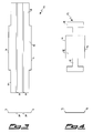
- Fig.3 shows a top plan view and a front view of the connecting element used in said first embodiment; and
- Fig.4 shows a top plan view and a front view of a connecting element that can be used in a second embodiment.
- With reference to figures 1-3, there is seen that a block assembly for buildings according to the present invention conventionally includes a first block B and a second block B' and, preferably, an insulating panel P therebetween. The sides of blocks B, B' facing panel P have at corresponding positions a pair of vertical coupling seats S, S' extending along the full height of the block assembly.
- The novel aspect of the present invention is provided by the plate-like connecting elements C as well as, preferably, by the shape of seats S, S' that are simple rectangular recesses.
- As shown in fig.3, a connecting element C has an elongated plate-like structure with a central wide portion W and two narrow end portions N. This shape of the connecting element C is devised so that the central wide portion W is wider than seats S, S' and therefore acts as a spacer between blocks B, B', whereas the end portions N are sized to enter with a minimum play seats S, S' where they are glued with a suitable adhesive (e.g. polyurethane foam).
- The plate-like structure of the connecting elements C allows them to be easily passed through the insulating panel P, when present, without any previous working of the latter and by means of a mere push since they act like a blade. In this way, the connecting elements C are fastened onto the insulating panel P very quickly and easily, without any risk of damaging panel P and without any problem even when the thickness of panel P is beyond the intended tolerances.
- To make easier the alignment of the connecting elements C and their correct horizontal penetration of panel P, said elements C are preferably provided with longitudinal edge fins F extending substantially perpendicular to the plane of the plate-like structure, typically only at the central portion W. Moreover, in order to increase the bending stiffness of the connecting elements C they are preferably provided with one or more longitudinal ribs R (two in the illustrated example).
- In the second embodiment illustrated in fig.4, there are provided connecting elements C' in which the central portion W' is still a simple rectangular plate, whereas the end portions N' are T-shaped. It is obvious that in this case also seats S, S' will correspondingly be T-shaped, and the introduction of the connecting elements C' will take place through vertical sliding rather than through horizontal sliding as in the first embodiment.
- This second embodiment allows to achieve a longitudinal resistance not only thanks to the gluing but also due to the mechanical coupling between ends N' and the corresponding seats S, S'. However, this implies an increased difficulty in assembling the block assembly and requires a stricter compliance with the manufacturing tolerances for the connecting elements C' and blocks B, B' with respect to the simple rectangular shape of the first embodiment.
- Furthermore, in this second type of connecting element C' there are provided longitudinal edge fins F' more pronounced than the similar fins F of fig.3. In this way, fins F' act also as bending reinforcements and it is unnecessary to provide ribs R.
- It is clear that the above-described and illustrated embodiments of the block assembly according to the invention are just examples susceptible of various modifications. In particular, it is possible to make connecting elements C, C' with other shapes as long as they retain a plate-like structure with a central wide portion W, W' that acts as a spacer between blocks B, B'. Moreover, it is obvious that the number and arrangement of the connecting elements and of the corresponding seats may change according to specific manufacturing needs.
Claims (10)
- Block assembly for buildings including a first block (B) and a second block (B') that have at least one pair of vertical coupling seats (S, S') formed in their mutually facing sides, as well as at least one pair of connecting elements (C; C') suitable to enter said seats (S, S'), characterized in that said connecting elements (C; C') have a plate-like structure with a central portion (W; W') wider than the seats (S, S') and end portions (N; N') sized to enter the seats (S, S') with a minimum play.
- Block assembly for buildings according to claim 1, characterized in that it further includes an insulating panel (P) arranged between the two blocks (B, B').
- Block assembly for buildings according to the preceding claim, characterized in that the insulating panel (P) is made up of at least two panels having different characteristics and arranged slightly staggered.
- Block assembly for buildings according to claim 1 or 2, characterized in that the end portions (N) of the connecting elements (C) are shaped so as to enter the seats (S, S') through horizontal sliding.
- Block assembly for buildings according to one of the preceding claims, characterized in that the end portions (N') of the connecting elements (C') are shaped so as to enter the seats (S, S') through vertical sliding.
- Block assembly for buildings according to one of the preceding claims, characterized in that the connecting elements (C') are provided with longitudinal edge fins (F; F') extending substantially perpendicular to the plane of the plate-like structure.
- Block assembly for buildings according to the preceding claim, characterized in that the longitudinal edge fins (F; F') are present only at the central portion (W; W').
- Block assembly for buildings according to one of the preceding claims, characterized in that the connecting elements (C; C') are provided with one or more longitudinal ribs (R) suitable to increase their bending stiffness.
- Method for manufacturing a block assembly for buildings according to one of the preceding claims, including the steps of:a) arranging a first block (B);b) arranging a second block (B');c) placing said blocks (B, B') so that they have at least one pair of vertical coupling seats (S, S') in their mutually facing sides;characterized in that it further includes the steps of:d) arranging at least one pair of connecting elements (C; C') having a plate-like structure with a central portion (W; W') wider than said seats (S, S') and end portions (N; N') sized to enter the seats (S, S') with a minimum play;e) introducing said end portions (N; N') into the seats (S; S') through horizontal or vertical sliding; andf) gluing said end portions (N; N') into the seats (S; S') by means of a suitable adhesive.
- Method according to claim 9, characterized in that it further includes the steps of:c') arranging an insulating panel (P);d') pushing the connecting elements (C; C') through said insulating panel (P) so as to fasten them onto the latter.
Priority Applications (1)
| Application Number | Priority Date | Filing Date | Title |
|---|---|---|---|
| EP20060425466 EP1876309B1 (en) | 2006-07-06 | 2006-07-06 | Block assembly for buildings and relevant manufacturing method |
Applications Claiming Priority (1)
| Application Number | Priority Date | Filing Date | Title |
|---|---|---|---|
| EP20060425466 EP1876309B1 (en) | 2006-07-06 | 2006-07-06 | Block assembly for buildings and relevant manufacturing method |
Publications (2)
| Publication Number | Publication Date |
|---|---|
| EP1876309A1 true EP1876309A1 (en) | 2008-01-09 |
| EP1876309B1 EP1876309B1 (en) | 2014-09-24 |
Family
ID=37461459
Family Applications (1)
| Application Number | Title | Priority Date | Filing Date |
|---|---|---|---|
| EP20060425466 Active EP1876309B1 (en) | 2006-07-06 | 2006-07-06 | Block assembly for buildings and relevant manufacturing method |
Country Status (1)
| Country | Link |
|---|---|
| EP (1) | EP1876309B1 (en) |
Cited By (1)
| Publication number | Priority date | Publication date | Assignee | Title |
|---|---|---|---|---|
| CN104481079A (en) * | 2014-12-04 | 2015-04-01 | 陈进 | Waterproof and mildewproof brick with heat-preservation plate |
Citations (5)
| Publication number | Priority date | Publication date | Assignee | Title |
|---|---|---|---|---|
| GB1598237A (en) * | 1978-03-22 | 1981-09-16 | Stones H B | Formwork for cementitious material |
| US4856249A (en) * | 1983-09-29 | 1989-08-15 | Nickerson David L | Insulated building block |
| EP1085137A1 (en) * | 1999-09-08 | 2001-03-21 | Fornaci Di Masserano Bruno Tarello S.R.L. | An insulating enbloc for buildings |
| EP1359263A1 (en) * | 2002-04-29 | 2003-11-05 | Jean-Marie Flechaire | Building module comprising two assembled panels |
| EP1557249A2 (en) * | 2004-01-23 | 2005-07-27 | Woschko Winlite GmbH | Method for producing a heat isolating multilayer brick and such brick |
-
2006
- 2006-07-06 EP EP20060425466 patent/EP1876309B1/en active Active
Patent Citations (5)
| Publication number | Priority date | Publication date | Assignee | Title |
|---|---|---|---|---|
| GB1598237A (en) * | 1978-03-22 | 1981-09-16 | Stones H B | Formwork for cementitious material |
| US4856249A (en) * | 1983-09-29 | 1989-08-15 | Nickerson David L | Insulated building block |
| EP1085137A1 (en) * | 1999-09-08 | 2001-03-21 | Fornaci Di Masserano Bruno Tarello S.R.L. | An insulating enbloc for buildings |
| EP1359263A1 (en) * | 2002-04-29 | 2003-11-05 | Jean-Marie Flechaire | Building module comprising two assembled panels |
| EP1557249A2 (en) * | 2004-01-23 | 2005-07-27 | Woschko Winlite GmbH | Method for producing a heat isolating multilayer brick and such brick |
Cited By (1)
| Publication number | Priority date | Publication date | Assignee | Title |
|---|---|---|---|---|
| CN104481079A (en) * | 2014-12-04 | 2015-04-01 | 陈进 | Waterproof and mildewproof brick with heat-preservation plate |
Also Published As
| Publication number | Publication date |
|---|---|
| EP1876309B1 (en) | 2014-09-24 |
Similar Documents
| Publication | Publication Date | Title |
|---|---|---|
| CN1307355C (en) | Installation method of panel and rail-type fixing apparatus | |
| US7516586B2 (en) | Hidden deck fastener system | |
| EP0483673A1 (en) | Construction method of boardlike building elements | |
| EP2126238A2 (en) | Ceiling suspension system | |
| JPH0420052B2 (en) | ||
| CN1151776A (en) | Insulating concrete form utilizing interlocking foam panels | |
| EP2581509A2 (en) | Connection apparatus | |
| KR20060090975A (en) | Floor | |
| EP3318686B1 (en) | Vacuum insulating material providing assembly | |
| EP1876309B1 (en) | Block assembly for buildings and relevant manufacturing method | |
| KR101526239B1 (en) | Structural steel for saddle and roof structure | |
| JP3979810B2 (en) | Insulating wall fasteners | |
| KR102246890B1 (en) | Roof panel assembly with bindding force and its construction method | |
| JP4011043B2 (en) | Door and manufacturing method thereof | |
| KR100438756B1 (en) | Fixer assembly for insulation of building | |
| EP1571270A1 (en) | Connecting device | |
| JP4283249B2 (en) | Formwork combined heat insulation panel and architectural formwork using the same | |
| JP4536000B2 (en) | Panel mounting structure | |
| JP4058049B2 (en) | Tightening material for building formwork | |
| JP4831781B2 (en) | Construction method for interior and exterior base material combined formwork insulation panels and concrete structures | |
| JP4057946B2 (en) | Formwork and insulation building materials | |
| KR200317486Y1 (en) | The connecting structure of standard forms | |
| JP3914238B2 (en) | Grating and lattice panel | |
| KR102876593B1 (en) | Insulation Fixtures | |
| CN206206953U (en) | Fastening piece |
Legal Events
| Date | Code | Title | Description |
|---|---|---|---|
| PUAI | Public reference made under article 153(3) epc to a published international application that has entered the european phase |
Free format text: ORIGINAL CODE: 0009012 |
|
| AK | Designated contracting states |
Kind code of ref document: A1 Designated state(s): AT BE BG CH CY CZ DE DK EE ES FI FR GB GR HU IE IS IT LI LT LU LV MC NL PL PT RO SE SI SK TR |
|
| AX | Request for extension of the european patent |
Extension state: AL BA HR MK YU |
|
| 17P | Request for examination filed |
Effective date: 20080417 |
|
| AKX | Designation fees paid |
Designated state(s): AT BE BG CH CY CZ DE DK EE ES FI FR GB GR HU IE IS IT LI LT LU LV MC NL PL PT RO SE SI SK TR |
|
| AXX | Extension fees paid |
Extension state: HR Payment date: 20080417 |
|
| GRAP | Despatch of communication of intention to grant a patent |
Free format text: ORIGINAL CODE: EPIDOSNIGR1 |
|
| INTG | Intention to grant announced |
Effective date: 20130919 |
|
| GRAS | Grant fee paid |
Free format text: ORIGINAL CODE: EPIDOSNIGR3 |
|
| GRAA | (expected) grant |
Free format text: ORIGINAL CODE: 0009210 |
|
| AK | Designated contracting states |
Kind code of ref document: B1 Designated state(s): AT BE BG CH CY CZ DE DK EE ES FI FR GB GR HU IE IS IT LI LT LU LV MC NL PL PT RO SE SI SK TR |
|
| AX | Request for extension of the european patent |
Extension state: HR |
|
| REG | Reference to a national code |
Ref country code: GB Ref legal event code: FG4D |
|
| REG | Reference to a national code |
Ref country code: CH Ref legal event code: EP |
|
| REG | Reference to a national code |
Ref country code: AT Ref legal event code: REF Ref document number: 688726 Country of ref document: AT Kind code of ref document: T Effective date: 20141015 |
|
| REG | Reference to a national code |
Ref country code: IE Ref legal event code: FG4D |
|
| REG | Reference to a national code |
Ref country code: DE Ref legal event code: R096 Ref document number: 602006043128 Country of ref document: DE Effective date: 20141106 |
|
| PG25 | Lapsed in a contracting state [announced via postgrant information from national office to epo] |
Ref country code: GR Free format text: LAPSE BECAUSE OF FAILURE TO SUBMIT A TRANSLATION OF THE DESCRIPTION OR TO PAY THE FEE WITHIN THE PRESCRIBED TIME-LIMIT Effective date: 20141225 Ref country code: FI Free format text: LAPSE BECAUSE OF FAILURE TO SUBMIT A TRANSLATION OF THE DESCRIPTION OR TO PAY THE FEE WITHIN THE PRESCRIBED TIME-LIMIT Effective date: 20140924 Ref country code: SE Free format text: LAPSE BECAUSE OF FAILURE TO SUBMIT A TRANSLATION OF THE DESCRIPTION OR TO PAY THE FEE WITHIN THE PRESCRIBED TIME-LIMIT Effective date: 20140924 Ref country code: LT Free format text: LAPSE BECAUSE OF FAILURE TO SUBMIT A TRANSLATION OF THE DESCRIPTION OR TO PAY THE FEE WITHIN THE PRESCRIBED TIME-LIMIT Effective date: 20140924 |
|
| REG | Reference to a national code |
Ref country code: CH Ref legal event code: NV Representative=s name: KEMIA SA, CH |
|
| REG | Reference to a national code |
Ref country code: LT Ref legal event code: MG4D Ref country code: NL Ref legal event code: VDEP Effective date: 20140924 |
|
| PG25 | Lapsed in a contracting state [announced via postgrant information from national office to epo] |
Ref country code: LV Free format text: LAPSE BECAUSE OF FAILURE TO SUBMIT A TRANSLATION OF THE DESCRIPTION OR TO PAY THE FEE WITHIN THE PRESCRIBED TIME-LIMIT Effective date: 20140924 Ref country code: CY Free format text: LAPSE BECAUSE OF FAILURE TO SUBMIT A TRANSLATION OF THE DESCRIPTION OR TO PAY THE FEE WITHIN THE PRESCRIBED TIME-LIMIT Effective date: 20140924 |
|
| REG | Reference to a national code |
Ref country code: AT Ref legal event code: MK05 Ref document number: 688726 Country of ref document: AT Kind code of ref document: T Effective date: 20140924 |
|
| PG25 | Lapsed in a contracting state [announced via postgrant information from national office to epo] |
Ref country code: NL Free format text: LAPSE BECAUSE OF FAILURE TO SUBMIT A TRANSLATION OF THE DESCRIPTION OR TO PAY THE FEE WITHIN THE PRESCRIBED TIME-LIMIT Effective date: 20140924 |
|
| PG25 | Lapsed in a contracting state [announced via postgrant information from national office to epo] |
Ref country code: SK Free format text: LAPSE BECAUSE OF FAILURE TO SUBMIT A TRANSLATION OF THE DESCRIPTION OR TO PAY THE FEE WITHIN THE PRESCRIBED TIME-LIMIT Effective date: 20140924 Ref country code: CZ Free format text: LAPSE BECAUSE OF FAILURE TO SUBMIT A TRANSLATION OF THE DESCRIPTION OR TO PAY THE FEE WITHIN THE PRESCRIBED TIME-LIMIT Effective date: 20140924 Ref country code: EE Free format text: LAPSE BECAUSE OF FAILURE TO SUBMIT A TRANSLATION OF THE DESCRIPTION OR TO PAY THE FEE WITHIN THE PRESCRIBED TIME-LIMIT Effective date: 20140924 Ref country code: ES Free format text: LAPSE BECAUSE OF FAILURE TO SUBMIT A TRANSLATION OF THE DESCRIPTION OR TO PAY THE FEE WITHIN THE PRESCRIBED TIME-LIMIT Effective date: 20140924 Ref country code: PT Free format text: LAPSE BECAUSE OF FAILURE TO SUBMIT A TRANSLATION OF THE DESCRIPTION OR TO PAY THE FEE WITHIN THE PRESCRIBED TIME-LIMIT Effective date: 20150126 Ref country code: IS Free format text: LAPSE BECAUSE OF FAILURE TO SUBMIT A TRANSLATION OF THE DESCRIPTION OR TO PAY THE FEE WITHIN THE PRESCRIBED TIME-LIMIT Effective date: 20150124 Ref country code: RO Free format text: LAPSE BECAUSE OF FAILURE TO SUBMIT A TRANSLATION OF THE DESCRIPTION OR TO PAY THE FEE WITHIN THE PRESCRIBED TIME-LIMIT Effective date: 20140924 |
|
| PG25 | Lapsed in a contracting state [announced via postgrant information from national office to epo] |
Ref country code: AT Free format text: LAPSE BECAUSE OF FAILURE TO SUBMIT A TRANSLATION OF THE DESCRIPTION OR TO PAY THE FEE WITHIN THE PRESCRIBED TIME-LIMIT Effective date: 20140924 Ref country code: PL Free format text: LAPSE BECAUSE OF FAILURE TO SUBMIT A TRANSLATION OF THE DESCRIPTION OR TO PAY THE FEE WITHIN THE PRESCRIBED TIME-LIMIT Effective date: 20140924 |
|
| REG | Reference to a national code |
Ref country code: DE Ref legal event code: R097 Ref document number: 602006043128 Country of ref document: DE |
|
| PG25 | Lapsed in a contracting state [announced via postgrant information from national office to epo] |
Ref country code: DK Free format text: LAPSE BECAUSE OF FAILURE TO SUBMIT A TRANSLATION OF THE DESCRIPTION OR TO PAY THE FEE WITHIN THE PRESCRIBED TIME-LIMIT Effective date: 20140924 |
|
| PLBE | No opposition filed within time limit |
Free format text: ORIGINAL CODE: 0009261 |
|
| STAA | Information on the status of an ep patent application or granted ep patent |
Free format text: STATUS: NO OPPOSITION FILED WITHIN TIME LIMIT |
|
| PG25 | Lapsed in a contracting state [announced via postgrant information from national office to epo] |
Ref country code: IT Free format text: LAPSE BECAUSE OF FAILURE TO SUBMIT A TRANSLATION OF THE DESCRIPTION OR TO PAY THE FEE WITHIN THE PRESCRIBED TIME-LIMIT Effective date: 20140924 |
|
| 26N | No opposition filed |
Effective date: 20150625 |
|
| REG | Reference to a national code |
Ref country code: DE Ref legal event code: R119 Ref document number: 602006043128 Country of ref document: DE |
|
| PG25 | Lapsed in a contracting state [announced via postgrant information from national office to epo] |
Ref country code: SI Free format text: LAPSE BECAUSE OF FAILURE TO SUBMIT A TRANSLATION OF THE DESCRIPTION OR TO PAY THE FEE WITHIN THE PRESCRIBED TIME-LIMIT Effective date: 20140924 Ref country code: MC Free format text: LAPSE BECAUSE OF FAILURE TO SUBMIT A TRANSLATION OF THE DESCRIPTION OR TO PAY THE FEE WITHIN THE PRESCRIBED TIME-LIMIT Effective date: 20140924 |
|
| REG | Reference to a national code |
Ref country code: CH Ref legal event code: PL |
|
| GBPC | Gb: european patent ceased through non-payment of renewal fee |
Effective date: 20150706 |
|
| PG25 | Lapsed in a contracting state [announced via postgrant information from national office to epo] |
Ref country code: LU Free format text: LAPSE BECAUSE OF FAILURE TO SUBMIT A TRANSLATION OF THE DESCRIPTION OR TO PAY THE FEE WITHIN THE PRESCRIBED TIME-LIMIT Effective date: 20150706 |
|
| REG | Reference to a national code |
Ref country code: IE Ref legal event code: MM4A |
|
| PG25 | Lapsed in a contracting state [announced via postgrant information from national office to epo] |
Ref country code: LI Free format text: LAPSE BECAUSE OF NON-PAYMENT OF DUE FEES Effective date: 20150731 Ref country code: CH Free format text: LAPSE BECAUSE OF NON-PAYMENT OF DUE FEES Effective date: 20150731 Ref country code: GB Free format text: LAPSE BECAUSE OF NON-PAYMENT OF DUE FEES Effective date: 20150706 Ref country code: DE Free format text: LAPSE BECAUSE OF NON-PAYMENT OF DUE FEES Effective date: 20160202 |
|
| REG | Reference to a national code |
Ref country code: FR Ref legal event code: ST Effective date: 20160331 Ref country code: CH Ref legal event code: AECN Ref country code: CH Ref legal event code: NV Representative=s name: IPWAY DI FRANCESCO FABIO AND CO., CH |
|
| PG25 | Lapsed in a contracting state [announced via postgrant information from national office to epo] |
Ref country code: FR Free format text: LAPSE BECAUSE OF NON-PAYMENT OF DUE FEES Effective date: 20150731 |
|
| PG25 | Lapsed in a contracting state [announced via postgrant information from national office to epo] |
Ref country code: IE Free format text: LAPSE BECAUSE OF NON-PAYMENT OF DUE FEES Effective date: 20150706 |
|
| PGRI | Patent reinstated in contracting state [announced from national office to epo] |
Ref country code: LI Effective date: 20160429 Ref country code: CH Effective date: 20160429 |
|
| REG | Reference to a national code |
Ref country code: CH Ref legal event code: NV Representative=s name: IPWAY DI FRANCESCO FABIO AND CO., CH Ref country code: CH Ref legal event code: PCOW Free format text: NEW ADDRESS: 1ST FLOOR RIVERVIEW HOUSE, 21-23 CITY QUAY, DUBLIN 2 (IE) Ref country code: CH Ref legal event code: PUE Owner name: MINUTERIE 3M S.R.L., IT Free format text: FORMER OWNER: STAMFORD CONSULTING LIMITED, IE |
|
| PG25 | Lapsed in a contracting state [announced via postgrant information from national office to epo] |
Ref country code: BG Free format text: LAPSE BECAUSE OF FAILURE TO SUBMIT A TRANSLATION OF THE DESCRIPTION OR TO PAY THE FEE WITHIN THE PRESCRIBED TIME-LIMIT Effective date: 20140924 Ref country code: HU Free format text: LAPSE BECAUSE OF FAILURE TO SUBMIT A TRANSLATION OF THE DESCRIPTION OR TO PAY THE FEE WITHIN THE PRESCRIBED TIME-LIMIT; INVALID AB INITIO Effective date: 20060706 |
|
| PG25 | Lapsed in a contracting state [announced via postgrant information from national office to epo] |
Ref country code: TR Free format text: LAPSE BECAUSE OF FAILURE TO SUBMIT A TRANSLATION OF THE DESCRIPTION OR TO PAY THE FEE WITHIN THE PRESCRIBED TIME-LIMIT Effective date: 20140924 |
|
| PG25 | Lapsed in a contracting state [announced via postgrant information from national office to epo] |
Ref country code: BE Free format text: LAPSE BECAUSE OF FAILURE TO SUBMIT A TRANSLATION OF THE DESCRIPTION OR TO PAY THE FEE WITHIN THE PRESCRIBED TIME-LIMIT Effective date: 20140924 |
|
| PGFP | Annual fee paid to national office [announced via postgrant information from national office to epo] |
Ref country code: CH Payment date: 20250801 Year of fee payment: 20 |