EP1876131A1 - Crime prevention device for elevator - Google Patents
Crime prevention device for elevator Download PDFInfo
- Publication number
- EP1876131A1 EP1876131A1 EP06713867A EP06713867A EP1876131A1 EP 1876131 A1 EP1876131 A1 EP 1876131A1 EP 06713867 A EP06713867 A EP 06713867A EP 06713867 A EP06713867 A EP 06713867A EP 1876131 A1 EP1876131 A1 EP 1876131A1
- Authority
- EP
- European Patent Office
- Prior art keywords
- elevator
- cage room
- security
- display
- cage
- Prior art date
- Legal status (The legal status is an assumption and is not a legal conclusion. Google has not performed a legal analysis and makes no representation as to the accuracy of the status listed.)
- Withdrawn
Links
Images




Classifications
-
- B—PERFORMING OPERATIONS; TRANSPORTING
- B66—HOISTING; LIFTING; HAULING
- B66B—ELEVATORS; ESCALATORS OR MOVING WALKWAYS
- B66B3/00—Applications of devices for indicating or signalling operating conditions of elevators
-
- B—PERFORMING OPERATIONS; TRANSPORTING
- B66—HOISTING; LIFTING; HAULING
- B66B—ELEVATORS; ESCALATORS OR MOVING WALKWAYS
- B66B5/00—Applications of checking, fault-correcting, or safety devices in elevators
- B66B5/0006—Monitoring devices or performance analysers
- B66B5/0012—Devices monitoring the users of the elevator system
-
- B—PERFORMING OPERATIONS; TRANSPORTING
- B66—HOISTING; LIFTING; HAULING
- B66B—ELEVATORS; ESCALATORS OR MOVING WALKWAYS
- B66B5/00—Applications of checking, fault-correcting, or safety devices in elevators
Definitions
- the present invention relates to an elevator security system that performs an elevator security operation.
- a conventional elevator security system detects when an abnormality occurs inside a cage room, and on the basis of this, announces that there is an abnormality, records video with a camera, and transmits information to a manager room.
- Patent Document 1 there is described an invention that is configured to prevent crime before it occurs by spotting a suspicious person with the potential to commit a crime hidden inside a cage that is on call and notifying a monitoring center so that staff in the monitoring center can convey a message of caution or a warning message by telephoning means.
- Patent Document 2 there is described an invention which, when a passenger operates a button on a cage operating panel after operating a destination floor registration button, conveys a message indicating that the inside of the cage is being monitored by a security camera to convey to a suspicious person that he/she is being monitored without exciting the suspicious person.
- Patent Document 1 JP-A-2001-302123 (pp. 2-3; FIG. 1)
- Patent Document 2 JP-A-2004-338828 (pp. 4-6; FIG. 1)
- Patent Document 1 is directed to suspicious persons hidden inside a cage that is on call, and there has been the problem that it cannot handle a suspicious person that has entered the elevator as an ordinary passenger, so that it is necessary to always station staff in a monitoring center. Further, in the elevator security system in Patent Document 2, it is necessary for a passenger to operate a button on the cage operating panel, so there has been the potential to excite suspicious persons.
- the present invention has been made in order to solve these problems, and it is an object thereof to obtain an elevator security system that is configured to control crime awareness of a user with the intent to commit a crime to prevent crime before it occurs by determining that there are few passengers inside a cage room of an elevator and displaying/announcing this to the inside of the cage room.
- An elevator security system pertaining to this invention comprises: cage room weight detecting means that detects the weight inside a cage room of an elevator; security-use display announcement determining means that determines the necessity of security-use display announcement by determining whether or not the cage room weight detected by the- cage room weight detecting means is within the range of a preset determination standard; and display announcing means that performs security-use display announcement to a display announcing device inside the cage room when it has been determined by the security-use display announcement determining means that security-use display announcement is necessary.
- this invention is disposed with: the cage room weight detecting means that detects the weight inside the cage room of the elevator; the security-use display announcement determining means that determines the necessity of security-use display announcement by determining whether or not the cage room weight detected by the cage room weight detecting means is within the range of the preset determination standard; and the display announcing means that performs security-use display announcement to the display announcing device inside the cage room when it has been determined by the security-use display announcement determining means that security-use display announcement is necessary.
- the invention can control crime awareness of a user with the intent to commit a crime to prevent crime before it occurs and can provide users with a sense of security, by determining that there are few passengers inside the cage room by the cage room weight and announcing with the display announcing device that the inside of the cage room is being monitored.
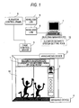
- FIG. 1 is a schematic diagram showing an elevator security system according to a first embodiment of this invention.
- a display device 1 that performs display during a security operation
- an announcing device 2 that performs announcing during the security operation
- a monitor device 3 that displays a monitor image
- a weighing device 4 that detects the weight inside the cage room.
- the display device 1, the announcing device 2, and the monitor device 3 form a display announcing device.
- An elevator control panel 6 controls the elevator security operation via a cage control device 5 and controls the display announcing device inside the cage room 10.
- the elevator control panel 6 is connected to a building manager PC (personal computer) 7 in a building management room via a wireless LAN 9 inside the elevator control panel 6 and a wireless LAN 8 inside the building manager PC 7.
- An elevator security system setting tool 12 which will be described later in a second embodiment, is installed in the building manager PC 7.
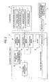
- FIG. 2 is a block diagram showing the elevator security system according to the first embodiment of this invention.
- Time detecting means 61 acquires the current time from a clock 62 inside the elevator control panel 6, and cage room weight detecting means 63 acquires the weight inside the cage room from the weighing device 4 of the cage room 10.
- Security-use display announcement determining means 64 determines whether or not display announcement conditions are satisfied from building specification data 65, the current time, and the weight inside the cage room 10, and when the conditions have been satisfied, display announcing means 66 outputs a display announcement to a display announcing device 11 inside the cage room 10.
- 61 to 66 are disposed in the elevator control panel 6.
- the display device 1, the announcing device 2, and the monitor device 3 and the like are disposed as the display announcing device 11 inside the cage room 10.
- FIG. 3 is a diagram showing building specification data of the elevator security system according to the first embodiment of this invention.
- FIG. 3 there are stored YES/NO information of the security display announcing device 11, the start and end times of security display announcement, determination standards of security display announcement that are set such that it can be determined when there are few passengers inside the cage room 10, the type of the display announcing device 11, a display announcement message that informs the inside of the cage room that the inside of the cage room is being monitored, and a monitor display image.
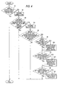
- FIG. 4 is a flowchart showing the operation of the elevator security system according to the first embodiment of this invention.
- step S1 it is determined whether or not there is the security display announcing device 11 from the value of a security display announcement YES/NO flag of the building specification data in FIG. 3.
- the flow proceeds to step S2, where the current time is acquired from the clock 62 inside the elevator control panel 6.
- step S3 it is determined whether or not the current time is within the range of the start time to end time of the building specification data shown in FIG.- 3.
- the weight inside the cage room 10 is acquired from the weighing device 4 inside the cage room.
- step S5 it is determined whether or not the weight inside the cage room 10 is within the range of the determination standard minimum value to maximum value of the building specification data shown in FIG. 3.
- step S6 it is determined whether or not there is the display device 1 from a display device YES/NO flag of the building specification data shown in FIG. 3.
- step S7 it is determined whether or not there is the display device 1 from a display device YES/NO flag of the building specification data shown in FIG. 3.
- step S7 When there is not the display device 1, then the flow proceeds to step S7.
- step S61 the display announcement message of the building specification data shown in FIG. 3 is outputted to the display device 1.
- step S7 it is determined whether or not there is the announcing device 2 from an announcing device YES/NO flag of the building specification data shown in FIG. 3.
- step S8 it is determined whether or not there is the announcing device 2 from an announcing device YES/NO flag of the building specification data shown in FIG. 3.
- step S8 it is determined whether or not there is the monitor device 3 from a monitor device YES/NO flag of the building specification data shown in FIG. 3.
- step S81 the monitor display image of the building specification data shown in FIG. 3 is outputted to the monitor device 3.
- security display announcement is automatically performed, whereby crime awareness of a user with the intent to commit a crime is controlled to prevent crime before it occurs, and a sense of security can be imparted to users.
- FIG. 5 is a diagram showing data held by a tool installed in a building manager PC of an elevator security system according to a second embodiment of this invention.
- FIG. 5 there are stored start and end times of security display announcement, determination standards of security display announcement, a display announcement message provided to the inside of the cage, and a monitor display image.
- FIG. 6 is a diagram showing a screen configuration of the tool installed in the building manager PC of the elevator security system according to the second embodiment of this invention.
- a manager password is inputted on a manager password input screen
- a menu screen is displayed.
- a time setting is selected on this menu screen
- a time setting screen is displayed.
- a determination standard setting is selected on the menu screen
- a determination standard setting screen is displayed.
- a display announcement message setting is selected on the menu screen
- a monitor display image setting is displayed.
- a monitor display image setting screen is displayed.
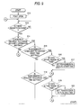
- FIG. 7 is a flowchart showing the operation of the building manager PC of the elevator security system according to the second embodiment of this invention.
- FIG. 8 is a diagram showing data sent by the tool installed in the building manager PC of the elevator security system according to the second embodiment of this invention.
- commands representing security operation setting change requests, subcommands allocated to each of the setting items corresponding to FIG. 5, and data that are setting values corresponding to the subcommands.
- FIG. 9 is a flowchart showing the operation of the elevator security system according to the second embodiment of this invention.
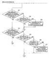
- FIG. 10 is a flowchart showing the operation of the elevator security system according to the second embodiment of this invention, and is a flowchart continued from FIG. 9. The second embodiment will be described with reference to FIG. 1 to FIG. 3.
- the elevator security system setting tool 12 is installed in the building manager PC 7 of FIG. 1, and the building manager PC 7 communicates with the elevator control panel 6 via the wireless LANs 8 and 9 to enable the setting content of-the building specification data 65 shown in FIG. 3 to be arbitrarily rewritten. That is, the settings of the building specification data shown in FIG. 3 inside the elevator control panel 6 can be changed using the elevator security system setting tool 12 installed in the building manager PC 7. As for this changing of settings, first, the holding data shown in FIG. 5 of the elevator security system setting tool 12 inside the building manager PC 7 is changed using the screen shown in FIG. 6 of the elevator security system setting tool 12 installed in the building manager PC 7. In this elevator security system setting tool 12, as shown in FIG.
- the manager password is inputted on the initial screen, whereby only the manager is enabled to change settings.
- the holding data of the elevator security system setting tool 12 whose setting has been changed is changed to the data of FIG. 8 and sent to the elevator control panel 6.
- the settings of the building specification data 65 can be changed.
- step S9 a transmission event occurs, in step S10, the port of the building manager PC 7 is opened, and in step S11, transmission data is transmitted.
- this transmission data has the configuration of commands and subcommands corresponding to individual setting items and data representing the setting content.
- step S12 of FIG. 9 the port is opened.
- step S13 it is determined whether or not there is a reception event, and when there is a reception event, in step S14 it is determined whether or not the command in the reception data is a security operation setting change request.
- step 14 when the command is not a security operation setting change request, the flow proceeds to A.
- step S14 when the command is a security operation setting change request, then in step S15, it is determined whether or not the subcommand is a start time setting change request.
- step S16 when the subcommand is a start time setting change request, then in step S16, it is determined whether or not the transmission data is within the range of time (00: 00 to 23: 59). When the transmission data is not within the range of time, then the flow proceeds to A.
- step S17 the transmission data is set to the display start time of the building specification data shown in FIG. 3 and the flow proceeds to A.
- step S15 when the subcommand is not a start time setting change request, then in step S18, it is determined whether or not the subcommand is an end time setting change request.
- step S19 it is determined whether or not the transmission data is within the range of time (00: 00 to 23: 59). When the transmission data is not within the range of time, then the flow proceeds to A. When the transmission data is within the range of time, then in step S20, the transmission data is set to the display end time of the building specification data shown in FIG. 3 and the flow proceeds to A.
- step S18 when the subcommand is not an end time setting change request, then in step S21, it is determined whether or not the subcommand is a determination standard minimum value setting change request.
- step S22 it is determined whether or not the transmission data is equal to or less than a maximum load capacity.
- the transmission data is not equal to or less than the maximum load capacity, then the flow proceeds to A.
- step S23 the transmission data is set to the determination standard minimum value of the building specification data shown in FIG. 3 and the flow proceeds to A.
- step S21 when the subcommand is not a determination standard minimum value setting change request, then in step S24, it is determined whether or not the subcommand is a determination standard maximum value setting change request.
- step S25 it is determined whether or not the transmission data is equal to or less than the maximum load capacity.
- step S26 it is determined whether or not the transmission data is equal to or greater than a minimum value.
- step S27 the transmission data is set to the determination standard maximum value of the building specification data shown in FIG. 3 and the flow proceeds to A.
- step S24 when the subcommand is not a determination standard maximum value change request, then the flow proceeds to step S28 of FIG. 10, and in step S28, it is determined whether or not the subcommand is a display announcement message setting change request.
- step S29 it is determined whether or not the string of the transmission data is valid.
- the string of the transmission data is not valid, then the flow proceeds to A.
- step S30 the transmission data is set to the display announcement message of the building specification data shown in FIG. 3 and the flow proceeds to A.
- step S28 when the subcommand is not a display announcement message setting change request, then in step S31, it is determined whether or not the subcommand is a monitor display image setting change request.
- step S32 it is determined whether or not the image of the transmission data is valid.
- the image of the transmission data is not valid, then the flow proceeds to A.
- step S33 the transmission data is set to the monitor display image of the building specification data shown in FIG. 3 and the flow proceeds to A. In A, the flow proceeds to step S13 of FIG. 9.
- the building specification data of the elevator control panel can be set via the wireless LANs from the building manager PC.
Landscapes
- Indicating And Signalling Devices For Elevators (AREA)
- Maintenance And Inspection Apparatuses For Elevators (AREA)
Abstract
Description
- The present invention relates to an elevator security system that performs an elevator security operation.
- A conventional elevator security system detects when an abnormality occurs inside a cage room, and on the basis of this, announces that there is an abnormality, records video with a camera, and transmits information to a manager room.
InPatent Document 1, there is described an invention that is configured to prevent crime before it occurs by spotting a suspicious person with the potential to commit a crime hidden inside a cage that is on call and notifying a monitoring center so that staff in the monitoring center can convey a message of caution or a warning message by telephoning means.
Further, inPatent Document 2, there is described an invention which, when a passenger operates a button on a cage operating panel after operating a destination floor registration button, conveys a message indicating that the inside of the cage is being monitored by a security camera to convey to a suspicious person that he/she is being monitored without exciting the suspicious person. - Patent Document 1:
JP-A-2001-302123
Patent Document 2:JP-A-2004-338828 - Conventional elevator security systems detect when an abnormality occurs inside a cage room and announce that there is an abnormality, but these are elevator security systems that operate after a crime occurs, and there has been the problem that a user cannot ride the elevator at ease.
The invention ofPatent Document 1 is directed to suspicious persons hidden inside a cage that is on call, and there has been the problem that it cannot handle a suspicious person that has entered the elevator as an ordinary passenger, so that it is necessary to always station staff in a monitoring center.
Further, in the elevator security system inPatent Document 2, it is necessary for a passenger to operate a button on the cage operating panel, so there has been the potential to excite suspicious persons. - The present invention has been made in order to solve these problems, and it is an object thereof to obtain an elevator security system that is configured to control crime awareness of a user with the intent to commit a crime to prevent crime before it occurs by determining that there are few passengers inside a cage room of an elevator and displaying/announcing this to the inside of the cage room.
- An elevator security system pertaining to this invention comprises: cage room weight detecting means that detects the weight inside a cage room of an elevator; security-use display announcement determining means that determines the necessity of security-use display announcement by determining whether or not the cage room weight detected by the- cage room weight detecting means is within the range of a preset determination standard; and display announcing means that performs security-use display announcement to a display announcing device inside the cage room when it has been determined by the security-use display announcement determining means that security-use display announcement is necessary.
- As described above, this invention is disposed with: the cage room weight detecting means that detects the weight inside the cage room of the elevator; the security-use display announcement determining means that determines the necessity of security-use display announcement by determining whether or not the cage room weight detected by the cage room weight detecting means is within the range of the preset determination standard; and the display announcing means that performs security-use display announcement to the display announcing device inside the cage room when it has been determined by the security-use display announcement determining means that security-use display announcement is necessary. Thus, the invention can control crime awareness of a user with the intent to commit a crime to prevent crime before it occurs and can provide users with a sense of security, by determining that there are few passengers inside the cage room by the cage room weight and announcing with the display announcing device that the inside of the cage room is being monitored.
- FIG. 1 is a schematic diagram showing an elevator security system according to a first embodiment of this invention.
In FIG. 1, disposed inside acage room 10 are adisplay device 1 that performs display during a security operation, anannouncing device 2 that performs announcing during the security operation, amonitor device 3 that displays a monitor image, and aweighing device 4 that detects the weight inside the cage room. Thedisplay device 1, theannouncing device 2, and themonitor device 3 form a display announcing device.
Anelevator control panel 6 controls the elevator security operation via acage control device 5 and controls the display announcing device inside thecage room 10. Further, theelevator control panel 6 is connected to a building manager PC (personal computer) 7 in a building management room via awireless LAN 9 inside theelevator control panel 6 and awireless LAN 8 inside the building manager PC 7. An elevator securitysystem setting tool 12, which will be described later in a second embodiment, is installed in the building manager PC 7. - FIG. 2 is a block diagram showing the elevator security system according to the first embodiment of this invention.
In FIG. 2, 1 to 4 and 6 to 10 represent the same things as those in FIG. 1. Time detecting means 61 acquires the current time from aclock 62 inside theelevator control panel 6, and cage room weight detecting means 63 acquires the weight inside the cage room from theweighing device 4 of thecage room 10. Security-use display announcement determining means 64 determines whether or not display announcement conditions are satisfied frombuilding specification data 65, the current time, and the weight inside thecage room 10, and when the conditions have been satisfied, display announcing means 66 outputs a display announcement to adisplay announcing device 11 inside thecage room 10. 61 to 66 are disposed in theelevator control panel 6.
Thedisplay device 1, theannouncing device 2, and themonitor device 3 and the like are disposed as thedisplay announcing device 11 inside thecage room 10. - FIG. 3 is a diagram showing building specification data of the elevator security system according to the first embodiment of this invention.
In FIG. 3, there are stored YES/NO information of the securitydisplay announcing device 11, the start and end times of security display announcement, determination standards of security display announcement that are set such that it can be determined when there are few passengers inside thecage room 10, the type of thedisplay announcing device 11, a display announcement message that informs the inside of the cage room that the inside of the cage room is being monitored, and a monitor display image.
FIG. 4 is a flowchart showing the operation of the elevator security system according to the first embodiment of this invention. - Next, the operation of the first embodiment will be described in accordance with the building specification data of FIG. 3 and the flowchart of FIG. 4.
In step S1, it is determined whether or not there is the securitydisplay announcing device 11 from the value of a security display announcement YES/NO flag of the building specification data in FIG. 3. When there is the securitydisplay announcing device 11, then the flow proceeds to step S2, where the current time is acquired from theclock 62 inside theelevator control panel 6. Next, in step S3, it is determined whether or not the current time is within the range of the start time to end time of the building specification data shown in FIG.- 3. When the current- time is within the designated range, then in step S4, the weight inside thecage room 10 is acquired from theweighing device 4 inside the cage room.
Next, in step S5, it is determined whether or not the weight inside thecage room 10 is within the range of the determination standard minimum value to maximum value of the building specification data shown in FIG. 3. When the weight inside thecage room 10 is within the determination standard range, then in step S6, it is determined whether or not there is thedisplay device 1 from a display device YES/NO flag of the building specification data shown in FIG. 3. When there is not thedisplay device 1, then the flow proceeds to step S7. When there is thedisplay device 1, then the flow proceeds to step S61, where the display announcement message of the building specification data shown in FIG. 3 is outputted to thedisplay device 1. - Next, in step S7, it is determined whether or not there is the announcing
device 2 from an announcing device YES/NO flag of the building specification data shown in FIG. 3. When there is not the announcingdevice 2, then the flow proceeds to step S8. When there is the announcingdevice 2, then in step S71, the display announcement message of the building specification data shown in FIG. 3 is outputted to theannouncing device 2.
Next, in step S8, it is determined whether or not there is themonitor device 3 from a monitor device YES/NO flag of the building specification data shown in FIG. 3. When there is themonitor device 3, then in step S81, the monitor display image of the building specification data shown in FIG. 3 is outputted to themonitor device 3.
It will be noted that processing ends when the weight inside thecage room 10 is not within the designated range in step S5.
Processing also ends when the current time is not within the designated range in step S3.
Further, processing also ends when there is not the securitydisplay announcing device 11 in step S1. - According to the first embodiment, when the state inside the cage room satisfies the determination standards for security display announcement, security display announcement is automatically performed, whereby crime awareness of a user with the intent to commit a crime is controlled to prevent crime before it occurs, and a sense of security can be imparted to users.
- FIG. 5 is a diagram showing data held by a tool installed in a building manager PC of an elevator security system according to a second embodiment of this invention.
In FIG. 5, there are stored start and end times of security display announcement, determination standards of security display announcement, a display announcement message provided to the inside of the cage, and a monitor display image. - FIG. 6 is a diagram showing a screen configuration of the tool installed in the building manager PC of the elevator security system according to the second embodiment of this invention.
In FIG. 6, when a manager password is inputted on a manager password input screen, a menu screen is displayed. When a time setting is selected on this menu screen, a time setting screen is displayed. When a determination standard setting is selected on the menu screen, a determination standard setting screen is displayed. When a display announcement message setting is selected on the menu screen, a display announcement message setting screen is displayed. When a monitor display image setting is selected on the menu screen, a monitor display image setting screen is displayed. When a value is inputted on the respective setting screens and a send button is pushed, the data of FIG. 8 is sent to theelevator control panel 6. - FIG. 7 is a flowchart showing the operation of the building manager PC of the elevator security system according to the second embodiment of this invention.
FIG. 8 is a diagram showing data sent by the tool installed in the building manager PC of the elevator security system according to the second embodiment of this invention.
In FIG. 8, there are stored commands representing security operation setting change requests, subcommands allocated to each of the setting items corresponding to FIG. 5, and data that are setting values corresponding to the subcommands. - FIG. 9 is a flowchart showing the operation of the elevator security system according to the second embodiment of this invention.
FIG. 10 is a flowchart showing the operation of the elevator security system according to the second embodiment of this invention, and is a flowchart continued from FIG. 9.
The second embodiment will be described with reference to FIG. 1 to FIG. 3. - In the second embodiment, the elevator security
system setting tool 12 is installed in thebuilding manager PC 7 of FIG. 1, and thebuilding manager PC 7 communicates with theelevator control panel 6 via thewireless LANs building specification data 65 shown in FIG. 3 to be arbitrarily rewritten. That is, the settings of the building specification data shown in FIG. 3 inside theelevator control panel 6 can be changed using the elevator securitysystem setting tool 12 installed in thebuilding manager PC 7.
As for this changing of settings, first, the holding data shown in FIG. 5 of the elevator securitysystem setting tool 12 inside thebuilding manager PC 7 is changed using the screen shown in FIG. 6 of the elevator securitysystem setting tool 12 installed in thebuilding manager PC 7. In this elevator securitysystem setting tool 12, as shown in FIG. 6, the manager password is inputted on the initial screen, whereby only the manager is enabled to change settings. Next, the holding data of the elevator securitysystem setting tool 12 whose setting has been changed is changed to the data of FIG. 8 and sent to theelevator control panel 6. Thus, in theelevator control panel 6, the settings of thebuilding specification data 65 can be changed. - Next, the transmission of the setting data of the
building specification data 65 to theelevator control panel 6 by the building manager PC of the second embodiment will be described in accordance with the flowchart of FIG. 7.
On the menu screen of FIG. 8 after password input, when a setting screen-that the user wishes to change is selected and a value representing the change content is inputted and the send button is clicked, in step S9, a transmission event occurs, in step S10, the port of thebuilding manager PC 7 is opened, and in step S11, transmission data is transmitted. As shown in FIG. 8, this transmission data has the configuration of commands and subcommands corresponding to individual setting items and data representing the setting content. - Next, processing where the
building specification data 65 transmitted from thebuilding manager PC 7 is received by theelevator control panel 6 will be described in accordance with the flowchart of FIGS. 9 and 10.
As shown in FIG. 2, thebuilding manager PC 7 and theelevator control panel 6 communicate via thewireless LANs step 14, when the command is not a security operation setting change request, the flow proceeds to A. - In step S14, when the command is a security operation setting change request, then in step S15, it is determined whether or not the subcommand is a start time setting change request. When the subcommand is a start time setting change request, then in step S16, it is determined whether or not the transmission data is within the range of time (00: 00 to 23: 59). When the transmission data is not within the range of time, then the flow proceeds to A. When the transmission data is within the range of time, then in step S17, the transmission data is set to the display start time of the building specification data shown in FIG. 3 and the flow proceeds to A.
In step S15, when the subcommand is not a start time setting change request, then in step S18, it is determined whether or not the subcommand is an end time setting change request. When the subcommand is an end time setting change request, then in step S19, it is determined whether or not the transmission data is within the range of time (00: 00 to 23: 59).
When the transmission data is not within the range of time, then the flow proceeds to A. When the transmission data is within the range of time, then in step S20, the transmission data is set to the display end time of the building specification data shown in FIG. 3 and the flow proceeds to A. - In step S18, when the subcommand is not an end time setting change request, then in step S21, it is determined whether or not the subcommand is a determination standard minimum value setting change request. When the subcommand is a determination standard minimum value setting change request, then in step S22, it is determined whether or not the transmission data is equal to or less than a maximum load capacity. When the transmission data is not equal to or less than the maximum load capacity, then the flow proceeds to A. When the transmission data is equal to or less than the maximum load capacity, then in step S23, the transmission data is set to the determination standard minimum value of the building specification data shown in FIG. 3 and the flow proceeds to A.
- In step S21, when the subcommand is not a determination standard minimum value setting change request, then in step S24, it is determined whether or not the subcommand is a determination standard maximum value setting change request. When the subcommand is a determination standard maximum value setting change request, then in step S25, it is determined whether or not the transmission data is equal to or less than the maximum load capacity. When the transmission data is not equal to or less than the maximum load capacity, then the flow proceeds to A. When the transmission data is equal to or less than the maximum load capacity, then in step S26, it is determined whether or not the transmission data is equal to or greater than a minimum value. When the transmission data is less than the minimum value, then the flow proceeds to A. When the transmission data is equal to or greater than the minimum value, then in step S27, the transmission data is set to the determination standard maximum value of the building specification data shown in FIG. 3 and the flow proceeds to A.
- In step S24, when the subcommand is not a determination standard maximum value change request, then the flow proceeds to step S28 of FIG. 10, and in step S28, it is determined whether or not the subcommand is a display announcement message setting change request. When the subcommand is a display announcement message setting change request, then in step S29, it is determined whether or not the string of the transmission data is valid. When the string of the transmission data is not valid, then the flow proceeds to A. When the string of the transmission data is valid, then in step S30, the transmission data is set to the display announcement message of the building specification data shown in FIG. 3 and the flow proceeds to A.
In step S28, when the subcommand is not a display announcement message setting change request, then in step S31, it is determined whether or not the subcommand is a monitor display image setting change request. When the subcommand is a monitor display image setting change request, then in step S32, it is determined whether or not the image of the transmission data is valid. When the image of the transmission data is not valid, then the flow proceeds to A. When the image of the transmission data is valid, then in step S33, the transmission data is set to the monitor display image of the building specification data shown in FIG. 3 and the flow proceeds to A.
In A, the flow proceeds to step S13 of FIG. 9. - According to the second embodiment, the building specification data of the elevator control panel can be set via the wireless LANs from the building manager PC.
-
- [FIG. 1] A schematic diagram showing an elevator security system according to a first embodiment of this invention.
- [FIG. 2] A block diagram showing the elevator security system according to the first embodiment of this invention.
- [FIG. 3] A diagram showing building specification data of the elevator security system according to the first embodiment of this invention.
- [FIG. 4] A flowchart showing the operation of the elevator security system according to the first embodiment of this invention.
- [FIG. 5] A diagram showing data held by a tool installed in a building manager PC of an elevator security system according to a second embodiment of this invention.
- [FIG. 6] A diagram showing the screen configuration of the tool installed in the building manager PC of the elevator security system according to the second embodiment of this invention.
- [FIG. 7] A flowchart showing the operation of the building manager PC of the elevator security system according to the second embodiment of this invention.
- [FIG. 8] A diagram showing data transmitted by the tool installed in the building manager PC of the elevator security system according to the second embodiment of this invention.
- [FIG. 9] A flowchart showing the operation of the elevator security system according to the second embodiment of this invention.
- [FIG. 10] A flowchart continued from FIG. 9 showing the operation of the elevator security system according to the second embodiment of this invention.
-
- 1
- Display Device
- 2
- Announcing Device
- 3
- Monitor Device
- 4
- Weighing Device
- 5
- Cage Control Device
- 6
- Elevator Control Panel
- 7
- Building Manager PC
- 8
- Wireless LAN (inside Building Manager PC)
- 9
- Wireless LAN (inside Elevator Control Device)
- 10
- Cage Room
- 11
- Display Announcing Device
- 12
- Elevator Security System Setting Tool
- 61
- Time Detecting Means
- 62
- Clock
- 63
- Cage Room Weight Detecting Means
- 64
- Security-Use Display Announcement Determining Means
- 65
- Building Specification Data
- 66
- Display Announcing Means
Claims (2)
- An elevator security system comprising:cage room weight detecting means that detects the weight inside a cage room of an elevator;security-use display announcement determining means that determines the necessity of security-use display announcement by determining whether or not the cage room weight detected by the cage room weight detecting means is within the range of a preset determination standard; anddisplay announcing means that performs security-use display announcement to a display announcing device inside the cage room when it has been determined by the security-use display announcement determining means that security-use display announcement is necessary.
- The elevator security system of claim 1, further comprising an elevator security system setting tool that is operated by a building manager to set the determination standard.
Applications Claiming Priority (2)
| Application Number | Priority Date | Filing Date | Title |
|---|---|---|---|
| JP2005129819A JP2006306558A (en) | 2005-04-27 | 2005-04-27 | Elevator crime prevention device |
| PCT/JP2006/302726 WO2006117916A1 (en) | 2005-04-27 | 2006-02-16 | Crime prevention device for elevator |
Publications (2)
| Publication Number | Publication Date |
|---|---|
| EP1876131A1 true EP1876131A1 (en) | 2008-01-09 |
| EP1876131A4 EP1876131A4 (en) | 2012-12-19 |
Family
ID=37307722
Family Applications (1)
| Application Number | Title | Priority Date | Filing Date |
|---|---|---|---|
| EP06713867A Withdrawn EP1876131A4 (en) | 2005-04-27 | 2006-02-16 | ANTI-CRIME DEVICE FOR ELEVATOR |
Country Status (5)
| Country | Link |
|---|---|
| EP (1) | EP1876131A4 (en) |
| JP (1) | JP2006306558A (en) |
| KR (1) | KR20070088315A (en) |
| CN (1) | CN1968883A (en) |
| WO (1) | WO2006117916A1 (en) |
Cited By (2)
| Publication number | Priority date | Publication date | Assignee | Title |
|---|---|---|---|---|
| EP2311766A4 (en) * | 2008-08-11 | 2014-08-20 | Mitsubishi Electric Corp | ELEVATOR OPERATION CONTROL DEVICE |
| US11708041B2 (en) | 2018-11-29 | 2023-07-25 | Toyota Jidosha Kabushiki Kaisha | Vehicle and passenger transportation system |
Families Citing this family (7)
| Publication number | Priority date | Publication date | Assignee | Title |
|---|---|---|---|---|
| US9086948B1 (en) | 2013-03-13 | 2015-07-21 | Allstate Insurance Company | Telematics based on handset movement within a moving vehicle |
| US12008653B1 (en) | 2013-03-13 | 2024-06-11 | Arity International Limited | Telematics based on handset movement within a moving vehicle |
| JP6163399B2 (en) * | 2013-09-19 | 2017-07-12 | 株式会社日立ビルシステム | Elevator behavior abnormality monitoring device |
| US9888392B1 (en) | 2015-07-24 | 2018-02-06 | Allstate Insurance Company | Detecting handling of a device in a vehicle |
| CN106241526A (en) * | 2015-08-04 | 2016-12-21 | 董岩 | A kind of method identifying the doubtful incident of violence of elevator |
| JP6567178B2 (en) * | 2016-05-23 | 2019-08-28 | 三菱電機株式会社 | Elevator crime prevention operation control device and crime prevention operation control method |
| JP6791399B2 (en) * | 2017-10-11 | 2020-11-25 | 三菱電機株式会社 | Elevator security system |
Family Cites Families (4)
| Publication number | Priority date | Publication date | Assignee | Title |
|---|---|---|---|---|
| JPH02117578A (en) * | 1988-10-21 | 1990-05-02 | Hitachi Ltd | Personalized terminal device for elevators |
| JP3226698B2 (en) * | 1994-02-24 | 2001-11-05 | 東芝エレベータ株式会社 | Elevator security equipment |
| JP2000118900A (en) * | 1998-10-19 | 2000-04-25 | Toshiba Fa Syst Eng Corp | Elevator monitoring device |
| JP2000351547A (en) * | 1999-06-11 | 2000-12-19 | Toshiba Corp | Elevator security driving device |
-
2005
- 2005-04-27 JP JP2005129819A patent/JP2006306558A/en active Pending
-
2006
- 2006-02-16 EP EP06713867A patent/EP1876131A4/en not_active Withdrawn
- 2006-02-16 WO PCT/JP2006/302726 patent/WO2006117916A1/en not_active Ceased
- 2006-02-16 CN CNA2006800003658A patent/CN1968883A/en active Pending
- 2006-02-16 KR KR1020067026649A patent/KR20070088315A/en not_active Ceased
Non-Patent Citations (2)
| Title |
|---|
| No further relevant documents disclosed * |
| See also references of WO2006117916A1 * |
Cited By (3)
| Publication number | Priority date | Publication date | Assignee | Title |
|---|---|---|---|---|
| EP2311766A4 (en) * | 2008-08-11 | 2014-08-20 | Mitsubishi Electric Corp | ELEVATOR OPERATION CONTROL DEVICE |
| US11708041B2 (en) | 2018-11-29 | 2023-07-25 | Toyota Jidosha Kabushiki Kaisha | Vehicle and passenger transportation system |
| US11912220B2 (en) | 2018-11-29 | 2024-02-27 | Toyota Jidosha Kabushiki Kaisha | Vehicle and passenger transportation system |
Also Published As
| Publication number | Publication date |
|---|---|
| CN1968883A (en) | 2007-05-23 |
| EP1876131A4 (en) | 2012-12-19 |
| KR20070088315A (en) | 2007-08-29 |
| JP2006306558A (en) | 2006-11-09 |
| WO2006117916A1 (en) | 2006-11-09 |
Similar Documents
| Publication | Publication Date | Title |
|---|---|---|
| FI117010B (en) | Elevator remote control | |
| US7557701B2 (en) | Building monitoring system | |
| EP2610203B1 (en) | Monitor control device | |
| EP1876131A1 (en) | Crime prevention device for elevator | |
| JP6889092B2 (en) | Elevator remote monitoring device and elevator remote monitoring system | |
| EP3381854B1 (en) | Visual status indicator for door and lock state | |
| US10227209B2 (en) | Orchestration of an occupant evacuation operation using destination entry fixtures | |
| JP4842134B2 (en) | Elevator monitoring system | |
| CN107777491A (en) | With the communication of the stranded passenger in transportation system | |
| JP5009206B2 (en) | Security equipment | |
| JP6194061B1 (en) | Elevator system and elevator control method | |
| JP2009214998A (en) | Elevator control system | |
| CN112689983A (en) | Server, user terminal device, electronic device, and control method thereof | |
| JP4676248B2 (en) | Elevator remote video monitoring system | |
| JP4907162B2 (en) | Elevator use support system | |
| JP2004359405A (en) | Elevator remote rescue method in case of earthquake | |
| KR20180032452A (en) | An emergency display call system enable automatic connecting with wireless or wire for eleator | |
| KR20150093327A (en) | Monitoring system for detecting emergency situation of elevator | |
| JP2004043156A (en) | Information notification control device for elevator | |
| KR101850694B1 (en) | Elevator control system | |
| JP7107899B2 (en) | Elevator monitoring terminal device | |
| JP2024147938A (en) | Control center device, elevator system and entrapment determination method | |
| CN114401916B (en) | Elevator system | |
| JP5709330B2 (en) | Elevator system, content transmission control device used therefor, and content transmission control method | |
| JP2004338860A (en) | Elevator confinement rescue system |
Legal Events
| Date | Code | Title | Description |
|---|---|---|---|
| PUAI | Public reference made under article 153(3) epc to a published international application that has entered the european phase |
Free format text: ORIGINAL CODE: 0009012 |
|
| 17P | Request for examination filed |
Effective date: 20061130 |
|
| AK | Designated contracting states |
Kind code of ref document: A1 Designated state(s): DE |
|
| DAX | Request for extension of the european patent (deleted) | ||
| RBV | Designated contracting states (corrected) |
Designated state(s): DE |
|
| A4 | Supplementary search report drawn up and despatched |
Effective date: 20121121 |
|
| RIC1 | Information provided on ipc code assigned before grant |
Ipc: B66B 3/00 20060101AFI20121115BHEP Ipc: B66B 5/00 20060101ALI20121115BHEP |
|
| STAA | Information on the status of an ep patent application or granted ep patent |
Free format text: STATUS: THE APPLICATION IS DEEMED TO BE WITHDRAWN |
|
| 18D | Application deemed to be withdrawn |
Effective date: 20130621 |