EP1876078A2 - Method of determining a control current in an electric actuator - Google Patents
Method of determining a control current in an electric actuator Download PDFInfo
- Publication number
- EP1876078A2 EP1876078A2 EP07019587A EP07019587A EP1876078A2 EP 1876078 A2 EP1876078 A2 EP 1876078A2 EP 07019587 A EP07019587 A EP 07019587A EP 07019587 A EP07019587 A EP 07019587A EP 1876078 A2 EP1876078 A2 EP 1876078A2
- Authority
- EP
- European Patent Office
- Prior art keywords
- current
- valve
- actuator
- determined
- measuring
- Prior art date
- Legal status (The legal status is an assumption and is not a legal conclusion. Google has not performed a legal analysis and makes no representation as to the accuracy of the status listed.)
- Granted
Links
- 238000000034 method Methods 0.000 title claims abstract description 86
- 230000001419 dependent effect Effects 0.000 claims abstract description 13
- 239000012530 fluid Substances 0.000 claims abstract description 13
- 238000004364 calculation method Methods 0.000 claims abstract description 9
- 230000005291 magnetic effect Effects 0.000 claims description 87
- 230000004907 flux Effects 0.000 claims description 25
- 238000012937 correction Methods 0.000 claims description 11
- 230000006870 function Effects 0.000 claims description 5
- 230000008859 change Effects 0.000 claims description 2
- 230000005294 ferromagnetic effect Effects 0.000 claims 1
- 230000001105 regulatory effect Effects 0.000 abstract description 10
- 230000008569 process Effects 0.000 abstract description 5
- 230000000694 effects Effects 0.000 abstract description 2
- 238000011088 calibration curve Methods 0.000 abstract 1
- 239000007788 liquid Substances 0.000 abstract 1
- 238000004519 manufacturing process Methods 0.000 description 14
- 230000001939 inductive effect Effects 0.000 description 9
- 238000005259 measurement Methods 0.000 description 6
- 238000007789 sealing Methods 0.000 description 5
- 230000033228 biological regulation Effects 0.000 description 4
- 230000001276 controlling effect Effects 0.000 description 4
- 230000006698 induction Effects 0.000 description 4
- 230000008901 benefit Effects 0.000 description 3
- 238000006073 displacement reaction Methods 0.000 description 3
- XEEYBQQBJWHFJM-UHFFFAOYSA-N Iron Chemical compound [Fe] XEEYBQQBJWHFJM-UHFFFAOYSA-N 0.000 description 2
- 238000010586 diagram Methods 0.000 description 2
- 239000003302 ferromagnetic material Substances 0.000 description 2
- 230000001965 increasing effect Effects 0.000 description 2
- 238000009434 installation Methods 0.000 description 2
- 239000000463 material Substances 0.000 description 2
- 230000035699 permeability Effects 0.000 description 2
- 241001136792 Alle Species 0.000 description 1
- 238000010276 construction Methods 0.000 description 1
- 238000013461 design Methods 0.000 description 1
- 239000006185 dispersion Substances 0.000 description 1
- 238000002474 experimental method Methods 0.000 description 1
- 210000003746 feather Anatomy 0.000 description 1
- 230000006872 improvement Effects 0.000 description 1
- 230000010354 integration Effects 0.000 description 1
- 229910052742 iron Inorganic materials 0.000 description 1
- 239000002655 kraft paper Substances 0.000 description 1
- 238000000691 measurement method Methods 0.000 description 1
- 230000009467 reduction Effects 0.000 description 1
- 230000001953 sensory effect Effects 0.000 description 1
- 238000012360 testing method Methods 0.000 description 1
- 238000012546 transfer Methods 0.000 description 1
- 230000007704 transition Effects 0.000 description 1
Images


Classifications
-
- B—PERFORMING OPERATIONS; TRANSPORTING
- B60—VEHICLES IN GENERAL
- B60T—VEHICLE BRAKE CONTROL SYSTEMS OR PARTS THEREOF; BRAKE CONTROL SYSTEMS OR PARTS THEREOF, IN GENERAL; ARRANGEMENT OF BRAKING ELEMENTS ON VEHICLES IN GENERAL; PORTABLE DEVICES FOR PREVENTING UNWANTED MOVEMENT OF VEHICLES; VEHICLE MODIFICATIONS TO FACILITATE COOLING OF BRAKES
- B60T8/00—Arrangements for adjusting wheel-braking force to meet varying vehicular or ground-surface conditions, e.g. limiting or varying distribution of braking force
- B60T8/32—Arrangements for adjusting wheel-braking force to meet varying vehicular or ground-surface conditions, e.g. limiting or varying distribution of braking force responsive to a speed condition, e.g. acceleration or deceleration
- B60T8/34—Arrangements for adjusting wheel-braking force to meet varying vehicular or ground-surface conditions, e.g. limiting or varying distribution of braking force responsive to a speed condition, e.g. acceleration or deceleration having a fluid pressure regulator responsive to a speed condition
- B60T8/36—Arrangements for adjusting wheel-braking force to meet varying vehicular or ground-surface conditions, e.g. limiting or varying distribution of braking force responsive to a speed condition, e.g. acceleration or deceleration having a fluid pressure regulator responsive to a speed condition including a pilot valve responding to an electromagnetic force
- B60T8/3615—Electromagnetic valves specially adapted for anti-lock brake and traction control systems
- B60T8/3655—Continuously controlled electromagnetic valves
- B60T8/366—Valve details
- B60T8/367—Seat valves, e.g. poppet valves
-
- B—PERFORMING OPERATIONS; TRANSPORTING
- B60—VEHICLES IN GENERAL
- B60T—VEHICLE BRAKE CONTROL SYSTEMS OR PARTS THEREOF; BRAKE CONTROL SYSTEMS OR PARTS THEREOF, IN GENERAL; ARRANGEMENT OF BRAKING ELEMENTS ON VEHICLES IN GENERAL; PORTABLE DEVICES FOR PREVENTING UNWANTED MOVEMENT OF VEHICLES; VEHICLE MODIFICATIONS TO FACILITATE COOLING OF BRAKES
- B60T8/00—Arrangements for adjusting wheel-braking force to meet varying vehicular or ground-surface conditions, e.g. limiting or varying distribution of braking force
- B60T8/32—Arrangements for adjusting wheel-braking force to meet varying vehicular or ground-surface conditions, e.g. limiting or varying distribution of braking force responsive to a speed condition, e.g. acceleration or deceleration
- B60T8/34—Arrangements for adjusting wheel-braking force to meet varying vehicular or ground-surface conditions, e.g. limiting or varying distribution of braking force responsive to a speed condition, e.g. acceleration or deceleration having a fluid pressure regulator responsive to a speed condition
- B60T8/36—Arrangements for adjusting wheel-braking force to meet varying vehicular or ground-surface conditions, e.g. limiting or varying distribution of braking force responsive to a speed condition, e.g. acceleration or deceleration having a fluid pressure regulator responsive to a speed condition including a pilot valve responding to an electromagnetic force
- B60T8/3615—Electromagnetic valves specially adapted for anti-lock brake and traction control systems
- B60T8/363—Electromagnetic valves specially adapted for anti-lock brake and traction control systems in hydraulic systems
-
- B—PERFORMING OPERATIONS; TRANSPORTING
- B60—VEHICLES IN GENERAL
- B60T—VEHICLE BRAKE CONTROL SYSTEMS OR PARTS THEREOF; BRAKE CONTROL SYSTEMS OR PARTS THEREOF, IN GENERAL; ARRANGEMENT OF BRAKING ELEMENTS ON VEHICLES IN GENERAL; PORTABLE DEVICES FOR PREVENTING UNWANTED MOVEMENT OF VEHICLES; VEHICLE MODIFICATIONS TO FACILITATE COOLING OF BRAKES
- B60T8/00—Arrangements for adjusting wheel-braking force to meet varying vehicular or ground-surface conditions, e.g. limiting or varying distribution of braking force
- B60T8/32—Arrangements for adjusting wheel-braking force to meet varying vehicular or ground-surface conditions, e.g. limiting or varying distribution of braking force responsive to a speed condition, e.g. acceleration or deceleration
- B60T8/34—Arrangements for adjusting wheel-braking force to meet varying vehicular or ground-surface conditions, e.g. limiting or varying distribution of braking force responsive to a speed condition, e.g. acceleration or deceleration having a fluid pressure regulator responsive to a speed condition
- B60T8/50—Arrangements for adjusting wheel-braking force to meet varying vehicular or ground-surface conditions, e.g. limiting or varying distribution of braking force responsive to a speed condition, e.g. acceleration or deceleration having a fluid pressure regulator responsive to a speed condition having means for controlling the rate at which pressure is reapplied to or released from the brake
-
- H—ELECTRICITY
- H01—ELECTRIC ELEMENTS
- H01F—MAGNETS; INDUCTANCES; TRANSFORMERS; SELECTION OF MATERIALS FOR THEIR MAGNETIC PROPERTIES
- H01F7/00—Magnets
- H01F7/06—Electromagnets; Actuators including electromagnets
- H01F7/08—Electromagnets; Actuators including electromagnets with armatures
- H01F7/18—Circuit arrangements for obtaining desired operating characteristics, e.g. for slow operation, for sequential energisation of windings, for high-speed energisation of windings
- H01F7/1844—Monitoring or fail-safe circuits
Definitions
- the invention relates inter alia to a method for calculating a drive current of at least one electrically controllable actuating device, for example a solenoid valve, for controlling the differential pressure-dependent flow G ( ⁇ P , I, KG) of a fluid according to the preamble of claim 1. Furthermore, the invention relates to a method for Calibration or mechanical adjustment of a positioning device and a positioning device according to the preamble of claim 11.
- the invention describes a method for measuring the pressure of a fluid according to the preamble of claim 20.
- An analogized switching valve is a current-controlled solenoid valve, which is designed to fully open or close, but is operated by targeted current setting so that this has analog control properties.
- a method for detecting the switching point of an analogously usable switching valve, in particular for determining the pressure conditions from the current profile of the Ventilan tenustromes goes out of the EP 0 813 481 B1 (P 7565).
- the pressure gradient or flow G of a corresponding analogized switching valve can be depending on the differential pressure by varying the current through the solenoid of the valve.
- the volume flow Q is difficult to set in the control and depends inter alia on the differential pressure Ap and the current I through the solenoid of the valve.
- this dependency can not easily be stored in a once defined map, since even small production-related tolerances of the valve components have a great influence on the functional relationship between flow and drive current. Therefore, it is necessary to individually determine a map during the manufacture of the valves for each valve and store it in a memory of the electronics of the controller.
- the unpublished DE 103 21 783.5 (P 10697) describes a learning method for valve characteristics of analog valves and analogized switching valves, respectively.
- a calibration of the hydraulic valves during the operation of the ABS brake device is performed, in which a drive characteristic or corresponding correction values for correcting an existing drive characteristic are determined by a learning process. It is characteristic of this learning method that it extends over several cycles of anti-lock control. In each suitable cycle, the required pressure build-up times are collected and it is calculated using the data obtained from the current cycle Parameter causes an increase of the characteristic according to a recursive formula. This method is used to improve an existing control characteristic and therefore requires an already existing characteristic.
- the aim of the invention is now to provide a method for determining characteristics, valve characteristics or valve characteristics, which leads to a more accurate control of the solenoid valves described above, without the need for elaborate individual valve calibration must be performed during production or at the end of the tape.
- actuators means valves and valves for adjusting a fluid flow.
- the actuating device used is preferably a valve.
- the actuator preferably has a fully open and a fully closed position.
- the valve assumes one of these positions, caused by a reset element.
- a suitable restoring element may preferably be a spring which has a defined force / displacement characteristic, which can be approximated in particular by a straight line equation.
- the method according to the invention is preferably used in an electro-hydraulic brake control device for motor vehicles.
- the method according to the invention preferably also relates to a method for adjusting or regulating a pressure gradient of a positioning device.
- the required characteristics or parameters or parameters for calibration are determined without the use of pressurizations of the actuator.
- a separate pressurization during the determination of the characteristics or parameters by means of a pneumatic or hydraulic measuring arrangement for determining the characteristics can therefore be omitted.
- the invention thus relates in particular to a method for determining particularly accurate actuating device characteristics or parameters during the operation of a motor vehicle, which is equipped with a brake system which in particular has control valves for regulating the brake pressure.
- the method according to the invention leads, inter alia, to the advantage that a manufactured actuating device or an entire hydraulic unit does not, as previously required, be individually defined in a test bench using defined Press must be measured. It is sufficient according to the method of the invention that an electronic control, which is connected to the actuator or to the hydraulic unit, measures the electromechanical and magnetic properties of the actuator. These properties are in particular substantially exactly the individual magnetic and mechanical characteristics KG ind of the actuating device, which are essentially responsible for the production-related dispersion in the characteristic curve. The less production-related scattering characteristics of the actuator can be defined by further, general characteristics KG all once for the series and store permanently in the electronic control unit. From the characteristics then the Stellellakennline and thus the required differential pressure-dependent drive current for the actuator can be calculated.
- the method according to the invention further has the advantage that the method, which is preferably done according to the invention, as often as desired, in particular at regular intervals even after installation in a vehicle can be carried out independently.
- This makes it possible for the system to recalibrate at regular intervals.
- the first time it is thus still possible for the first time to take into account any changes in the arrangement due to external influences, such as wear, which only occur a long time after the manufacture of the actuator.
- the characteristic curves can therefore be determined automatically by the controller, even at the time after installation in a vehicle, without a measuring apparatus.
- an additional data transfer step from an otherwise required measuring arrangement for determining the characteristic curves in the control unit can be dispensed with.
- the pressure difference ⁇ P must be known by the electronic controller in addition to the valve for setting a certain flow rate G with the determined characteristics. This is preferably calculated in a model-based manner in a manner known per se according to the method, or is measured by sensors. If, for example, only one pressure sensor is present in the region of the tandem skin cylinder, the differential pressure is determined, in particular, from the time profile of the parameters influencing the pressure, such as pressure build-up times, etc. Especially in this integrating method for determining the pressure gradient, the accuracy of the flow is of great importance.
- the causes for the remaining scatter of the characteristic curves or in particular their gradients predominantly on the tolerances of the mechanics, such as the fluctuating spring force F spring , and the magnetic field line circuit (eg magnetic resistance of the air gaps, etc .) of the actuator.
- the total magnetic resistance of the magnetic circuit is measured.
- the inductance L of the corresponding magnetic circuit based on the number of turns N of the coil, can be used as an equivalent physical quantity in a corresponding manner for carrying out the method according to the invention.
- the invention also relates to a valve according to claim 11, which is provided with one or more additional measuring elements, in particular measuring coils.
- the measuring coil can be electrically independent of the drive coil. However, according to a preferred embodiment it is possible to switch the measuring coil electrically in series with the drive coil. This has the advantage that only three control lines must be led to the outside.
- the invention additionally relates to a method for adjusting the open position and / or the flow of an actuating device, in particular a valve.
- the flow G of the actuating device or valve is in principle next to the differential pressure and the geometric flow properties determined by the force acting on the plunger of the relevant actuator (plunger force).
- the invention therefore preferably also relates to a method for adjusting or regulating the ram force of a positioning device.
- the plunger position, the plunger force or the flow of the actuator can be set or regulated in a particularly precise manner on the previously described control.
- all magnetic field-dependent sensors eg Hall sensors, MR sensors
- MR sensors magnetic field-dependent sensors
- the use of a coil appears particularly expedient due to the possibility of cost-effective production.
- the spring force, and if necessary the maximum ram stroke is preferably determined in a calibration routine. These quantities are then included in the force calculation.
- a special feature of the method according to the invention is, inter alia, that preferably a measurement of the magnetic flux is performed and in particular regulated according to this. This is useful because the magnetic force is directly dependent on the magnetic flux.
- the current through the coil is the determining factor.
- the maximum ram stroke within the actuator and in particular the spring force is measured.
- the force-displacement characteristic of the actuator can be defined very precisely, so that the flow of the valve can be controlled or controlled with very high accuracy.
- the invention further relates to the use of the inventive method for controlling or improving the manufacturing quality of a control device, in particular valve, in which the ram stroke and / or the spring force during or immediately after the production of the actuator or valve or the production of the hydraulic valve block is measured.
- the residual air gap and the tappet stroke are set solely by considering an electrical parameter of the actuator. This is very particularly preferred in that the magnetic resistance is measured when the actuator is closed and the magnetic resistance with the actuator open.
- the electrical, non-pressurized calibration method described above may additionally be added to this adjustment method.
- the unpressurized calibration procedure with pre-adjusted actuating device, essentially only a tolerance in the characteristic of the return spring has to be compensated by the method.
- the invention relates not only to a calibration method, but also to a method for determining pressure according to claim 20, wherein the force acting on the valve tappet force of the pressure in a hydraulic fluid is measured.
- this pressure measuring method of the invention underlying the general principle of ram force control is used.
- a further improvement of the method according to the invention results preferably in that after the calibration according to the invention additionally the above-mentioned learning method, as it is known from DE 103 21 783.5 is known, is performed.
- the measurement of the integral at the Spulenabgriff or at the tap of the measuring coil by means of a particularly simple design so-called electronic Irelandeckformerscnies is performed. It is a method for determining the magnetic flux in at least one electrically controllable via a driver stage inductive actuator or actuator device generally by evaluating or adjusting the actuator or actuator component induced voltage U ind by means of an electronic measuring device, wherein the am inductive actuator or actuator component voltage is actively held by the measuring device or the electronic control of the inductive actuating device or actuator component at a substantially constant value and the time t 1 is determined, in which flowing through the inductive component and the measuring device Current when switching on or off a voltage induced.
- the switch-off time t c which indicates the time between the switch-on t 0 and the time t 1 , or the turn-on time of the actuator component is determined.
- the invention also relates to an electronic circuit arrangement for determining the magnetic flux or the inductance of an inductive actuating device or actuator component, comprising a measuring device with signal input and signal output, wherein the signal input is electrically connected to the inductive component and the output provides an electrical signal that includes information about the time required to store the information stored in the inductive actuator or actuator device To completely dissipate energy at a constant voltage or to bring the current in the inductive actuator or actuator component completely to the desired maximum current.
- the signal output of the measuring device is supplied as the actual value of a control circuit whose controlled variable is the current through the inductive component.
- the measuring method and the circuit arrangement described above are expediently used instead of the measuring device for measuring the integrated voltage signal at the tap of the coil of the actuating device in the calibration method described at the beginning.
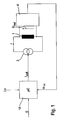
- EBS control device comprises a regulator housing (ECU) with a microcontroller system 18, as shown schematically in FIGS. 1, 2 and 4, and a valve block (HCU) connected to the regulator with electromagnetically operated valves used to control the hydraulic flow 1.
- the controller also includes a drive circuit (current source 3), with which the valve current I can be individually set pulse width modulated for each valve and also measured.
- corresponding valve drivers are provided for each valve, which are realized by means of individually controllable PWM driver stages.
- a measuring device 4 is provided, with which the induction voltage U ind can be measured.
- a signal ⁇ is available which is proportional to the integral over U ind (t).
- I is the coil current
- N is the number of turns of the spool
- RM total of the total magnetic resistance of the magnetic circuit in the valve.
- valve 1 measuring device 4 When switching off the valve current I in Fig. 1, there is a change in the magnetic flux ⁇ in valve 1, which can be measured by the connected to valve 1 measuring device 4 via induction voltage U ind . Measuring device 4 forms the time integral over the course of the induced Voltage U ind and supplies the integrated signal to the microcontroller 18. This signal is proportional to the magnetic flux ⁇ caused by the valve spool.
- An alternative measuring device for determining this integral is described below in connection with FIG. 9.
- valve current flowing through valve spool 1 forms therein the actual control value of the control.
- the pressure gradient G to be set is predetermined by the ABS / ESP control within the computing unit ⁇ C (EBS control unit).
- the differential pressure is known to the arithmetic unit. Depending on the features of the brake control device this is completely sensory or partially determined by a pressure model in a known manner.
- the spring force, the maximum ram stroke and the dependence of the magnetic flux on the valve current are determined once or at different times according to the measuring routine described below (recalibration). Thus, all acting forces and the calculated force / displacement function of the valve stem are known; it is possible to calculate the valve current required for the required pressure gradient.
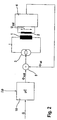
- FIG. 2 shows another possibility for realizing the invention with an additional coil control loop.
- the required pressure gradient G is likewise present in the arithmetic unit (.mu.C).
- the differential pressure is known to the arithmetic unit.
- the spring force and the maximum ram stroke are determined via the measuring routine described below.
- the magnetic flux is detected with a measuring coil 2.
- the measuring coil is arranged to detect the effective magnetic flux through yoke and armature.
- a voltage U ind is induced in the measuring coil whose integral is proportional to the existing magnetic flux.
- the signal ⁇ is which is derived from the signal generated by step 4 integral value, it is intended in differentiating stage 5 with the signal ⁇ together and forms the setpoint variable for the valve driver.
- the measuring routine for determining the valve-specific parameters can be repeated at any time, even during vehicle operation (recalibration), for example to compensate for operational changes or wear of the mechanical or even the electrical components.
- the electronic control increases the coil current via driver 3 until the magnetic flux in the magnetic circuit corresponds to the calculated flux.
- FIG. 2 it is a ram force control in which the ram position depends on the pressure conditions at the valve.
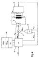
- Fig. 3 shows the structure of a present invention usable solenoid valve in an ABS / ESP valve block.
- the valve according to the examples according to the invention is a normally open valve, which is operated in a manner known per se by means of a PWM-regulated current.
- Corresponding valves are under the name analogized digital valves "AD valve" known.
- the construction of such an SO-AD valve, in particular the components of the magnetic circuit guiding the field lines, will be described in more detail below.
- the energized valve coil 6 serves to move the axially guided in the valve housing 13 armature 7, which engages sealingly via plunger 8 in the valve seat 9. Hydraulic fluid flows via valve inlet 10 to the valve seat 9 and escapes via outlet 12.
- Spring 11 pushes the plunger and armature into the open position, provided that no current flows through coil 6.
- coil 6 penetrate the magnetic field lines yoke 14 and penetrate into the housing 13 a.
- the transition point between the yoke 14 and the housing 13 forms the magnetic resistance RM LR2 .
- the field lines penetrate the air gap 15 between the armature 7 and the housing 13, wherein the magnetic resistance present at this location is designated by RM A.
- armature 7 and yoke 14 there is a further air gap, which is associated with the magnetic resistance RM LR1 .
- the size RM valve can be measured in the closed state and the size RM air results from the formula l ⁇ 0 * A At ker .
- a anchor is the specific for the valve series magnetically effective area of the armature 7 (model-specific characteristic KG all ) and 1 is the ram stroke.
- the actual measuring method does not determine the value for RM air directly but via a measurement of the magnetic resistance when the valve is fully open and subtracting the magnetic resistance of the closed valve. In this way, the ram stroke 1 can be determined.
- FIG. 3 also shows the measuring coil 2 required for carrying out the exemplary embodiment described in FIG. 2, which is positioned in the region of the yoke 14.
- Fig. 4 schematically illustrates another example of a control loop in which the plunger position 1 is controlled directly.
- the total magnetic resistance RM is composed of the magnetic resistance of the closed valve and the magnetic resistance of the air gap.
- the magnetic resistance of the closed valve can be determined by a unique measuring routine.
- the output of divider 17 is connected to differentiator 5.
- the current differential pressure needed.
- the current valve current is determined and multiplied by the number of turns of the exciter coil.
- the product is the flooding ⁇ (magnetic tension).
- the current magnetic voltage is divided by the current magnetic flux.
- the result is the current magnetic resistance.
- a setpoint / actual value comparison is carried out and the manipulated variable I (coil current) is generated from this.
- the method according to the example in FIG. 4 also offers the possibility of determining the pressure in the fluid lines connected to the valve without additional pressure sensors in the individual pressure sensors.
- the pressure can be calculated analogously to the method described above from the currently measured at this plunger position ram force in conjunction with the known general characteristics KG all of the valve.
- the input pressure is determined, for example, by the brake pedal operation.
- the input pressure deviates from the pressure in the individual hydraulic lines leading to the brake cylinders. Since, in principle, only the differential pressure prevailing at the valve can be determined according to the preceding measurement method, it may be necessary to determine the admission pressure by sensor (for example pressure sensor on the tandem master cylinder). However, the form can also be calculated by model considerations. Furthermore, it is possible, by considering certain operating conditions of the brake system to determine the pressure without precise knowledge of the form. In this way, a completely pressure sensorless pressure determination can be realized. This saves considerable costs for additional pressure sensors in an ABS / ESP brake control unit.
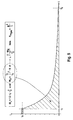
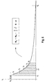
- FIG. 5 shows the current flow in a valve spool after switching off the flow at a closed valve.
- the magnetic resistance RM ges with a known coil turns N can be determined from the integral of the power curve.
- the physical relationship results from the formulas given in the box of FIG. 5, where W L is the magnetic energy of the magnetic circuit and R is the ohmic resistance of the electrical coil circuit.
- FIG. 6 An example for carrying out a measuring method for determining the magnetic resistance according to the principle in FIG. 5 is sketched in FIG. 6.
- a current value I 0 is set by the EBS control unit (regulated), in which the valve is securely closed.
- the duty cycle of the PWM control is set so that no more power is fed into the coil driver.
- the current stored by the inductor sounds through the Rezirkulations Kunststoffkeit the output stage.
- the current is first successively increased, starting from a suitably small current of, for example, I ⁇ 0, the stepwise increase.
- the current is initially maintained at a value I 1 at which the valve is just opened, ie at a higher current, the valve would close.
- the current is switched off and the time ⁇ 1 is measured until the current current value has fallen below a threshold value S (time t 2 ). Due to the open position of the valve results in a low inductance and thus a short time constant ⁇ 1 in the exponential Stromabkling .
- sub-image b the current waveform is shown when the corresponding valve is driven with a current I 2 , which causes a closing of the valve.
- the closing process can be seen on a short-term survey 71 of the current in the constant current range.
- the current is switched off as above, the current again sounds below the threshold S from.
- the time constant ⁇ 2 of the initially closed valve is higher due to the lower magnetic resistance (higher inductance) in sub-image b) than the corresponding time constant in sub-image a).
- the opening of the valve which is also recognizable at an elevation 72 in the course of the current, also causes an extension of the time constant.
- FIG. 8 schematically shows an example of an algorithm 82 for calculating the valve opening characteristic curve by means of the valve-specific individual characteristics KG ind (measuring method 81) determined according to the examples in FIGS. 5 to 7 in an electrohydraulic control device 82.
- the valve-specific individual parameters KG ind can generally be characteristic curves or parameters of the valve.
- a curve is needed for a valve control with high accuracy, which indicates the current necessary to open the valve at a predetermined differential pressure ⁇ P (differential pressure-dependent valve opening flow characteristic f ( ⁇ P)).
- KG all which are characteristic of the valve series, are specified on the input side in the controller. These can be designated by the model-specific anchor surface A anchor and the valve sealing A sealing closer. Furthermore, the actual differential pressure .DELTA.P for the relevant valve is specified at the input as a variable variable (Var), which is either determined by the sensor or approximately calculated by the EBS system from other variables.
- Var variable variable
- the current-dependent magnetic force F magn (I) can be calculated.
- the valve In the equilibrium state, the valve is just closed.
- the magnetic force F magn which is necessary for this, gives the holding current:
- F feather + F hydraulic F magn
- the differential pressure-dependent holding current for discrete differential pressures can therefore be calculated relatively accurately taking into account the valve sealing surface and the sealing cross section.
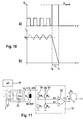
- the exemplary embodiment illustrated in FIG. 9a relates to a circuit arrangement as described in FIG. 1, with the difference that a rectangular shaper 19 shown in FIG. 11 is provided for the simplified measurement of the induction voltage.
- Rectangular former 19 can likewise advantageously be used instead of the measuring device 4 in FIG. 2.
- the EBS regulator comprises a driver circuit 3 (current source) with which the valve current I can be individually set and also pulse-width modulated for each valve.
- the induction voltage U ind in a simple manner over a time measurement, as sketched in part of image b) are measured.
- the magnetic flux in coil 1 of the actuator induces a voltage U L (terminal voltage) when switching off the current at the time t 0 , so that the current drops during the turn-off in a time t c to about the value 0.
- U L terminal voltage
- the voltage curve of U L is shown in detail in Fig. 10a).
- the meanwhile caused by the PWM valve control current profile is shown in Fig. 10b).
- the variables R L (resistance of the coil), U L (regulated Abkommutierwood), and I 0 (valve current) are the arithmetic unit 18 known.
- the time t c which is proportional to the inductance L is, is detected by means of rectangular shaper 19.
- an electrical signal At the output of rectangular shaper 19 is an electrical signal, which is proportional to t c . This signal is supplied via line 20 arithmetic unit 18 as actual size for the control to be made.
- Current source 3 is composed of a current driver 21 and a recirculation circuit 22, which regulates the recirculation current after switching off the current at time t 0 with a controllable resistance, wherein Rezirkulationswan 22 is driven by the arithmetic unit 18.
- a corresponding circuit for driving hydraulic valves is known from the patent application DE 102004017239.0 already known.
- a first voltage divider 51 consisting of resistors R 1 and 9R 1 is connected, which reduces the high voltage values U 0 at the signal input S + of the comparator 53 by about a factor of 10.
- a second voltage divider 52 generates at the input S- of the comparator 53 a reference voltage which is equal to half the logic supply voltage. Comparator 53 thus evaluates the difference of the signals S + and S-, whereby a suitable square-wave signal is generated.
- the current can be commutated after switching off within a relatively short time (less than 1 ms), as shown in Fig. 10b.
- the clamping voltage U L can be set to a constant value U const (FIG. 10 a).
- PWM pulse width modulated control
Abstract
Description
Die Erfindung betrifft unter anderem ein Verfahren zur Berechnung eines Ansteuerstroms mindestens eines elektrisch ansteuerbaren Stellgeräts, beispielsweise eines Magnetventils, zum Regeln des differenzdruckabhängigen Durchflusses G(ΔP,I,KG) eines Fluids gemäß Oberbegriff von Anspruch 1. Weiterhin betrifft die Erfindung ein Verfahren zur Kalibrierung oder mechanischen Justage eines Stellgeräts sowie ein Stellgerät gemäß Oberbegriff von Anspruch 11.The invention relates inter alia to a method for calculating a drive current of at least one electrically controllable actuating device, for example a solenoid valve, for controlling the differential pressure-dependent flow G (Δ P , I, KG) of a fluid according to the preamble of
Zusätzlich beschreibt die Erfindung ein Verfahren zur Druckmessung eines Fluids gemäß Oberbegriff von Anspruch 20.In addition, the invention describes a method for measuring the pressure of a fluid according to the preamble of
Es ist bekannt, in ABS-Steuergeräten für Kraftfahrzeugbremssysteme, aber auch in sogenannten Fahrdynamikreglern mit zusätzlichen Funktionen wie ESP etc., elektromagnetisch ansteuerbare analogisierte Ventile für eine verbesserte Regelung bzw. zur Geräuschminderung einzusetzen.It is known, in ABS control units for motor vehicle brake systems, but also in so-called vehicle dynamics controllers with additional functions such as ESP, etc., to use electromagnetically controllable analogized valves for improved control or noise reduction.
In neueren Generationen von Hydraulikregelvorrichtungen werden sogenannte analogisierte Schaltventile eingesetzt. Ein analogisiertes Schaltventil ist ein stromangesteuertes Magnetventil, welches an sich zum vollständigen Öffnen oder Schließen ausgelegt ist, jedoch durch gezielte Stromeinstellung so betrieben wird, dass dieses analoge Regeleigenschaften besitzt.In newer generations of hydraulic control devices so-called analogized switching valves are used. An analogized switching valve is a current-controlled solenoid valve, which is designed to fully open or close, but is operated by targeted current setting so that this has analog control properties.
Ein Verfahren zur Erkennung des Schaltpunktes eines analog einsetzbaren Schaltventils, insbesondere zur Bestimmung der Druckverhältnisse aus dem Stromverlauf des Ventilansteuerstromes geht aus der
Im Prinzip lässt sich demzufolge der Druckgradient oder Durchfluss G eines entsprechenden analogisierten Schaltventils in Abhängigkeit vom Differenzdruck durch Variation des Stroms durch die Magnetspule des Ventils einstellen. Der Volumenstrom Q ist im Bereich der Regelung allerdings schwierig einzustellen und hängt unter anderem vom Differenzdruck Δp und vom Strom I durch die Magnetspule des Ventils ab. Allerdings lässt sich diese Abhängigkeit nicht ohne weiteres in einem einmal festgelegten Kennfeld ablegen, da bereits geringe fertigungsbedingte Toleranzen der Ventilbauteile einen großen Einfluss auf den funktionalen Zusammenhang zwischen Durchfluss und Ansteuerstrom haben. Daher ist es erforderlich, während der Fertigung der Ventile für jedes Ventil individuell ein Kennfeld zu bestimmen und dieses in einem Speicher der Elektronik des Steuergeräts abzulegen. Zur Erstellung der individuellen Kennfelder ist jedoch ein aufwändiges Messverfahren mit definierten Druckbeaufschlagungen der Steuergeräte beim Zulieferer oder am Bandende beim Kraftfahrzeughersteller nötig. Die durch das aufwändige Messverfahren ermittelten Kennfelder können dann, wie dies beispielsweise in der
Die unveröffentlichte
Die vorstehend beschriebenen Verfahren zum Ermitteln der Kennfelder oder Kennlinien sind somit entweder nicht genaugenug oder sie können nur durch ein aufwändiges Messverfahren ermittelt werden, welches beim Lieferant oder am Bandende durchgeführt werden muss. Nur auf diese Weise können die den Druckverlauf beeinflussenden, fertigungsabhängigen individuellen Kenngrößen KGind eines Ventils, die sich z.B. aus den gemessenen Kennfeldern oder Kennlinien gewinnen lassen, ermitteln.The above-described methods for determining the maps or characteristics are thus either not exactly accurate or they can only be determined by a complex measuring method, which must be performed at the supplier or at the end of the tape. Only in this way can the pressure-influencing, production-dependent individual parameters KG ind of a valve, which can be obtained, for example, from the measured characteristic diagrams or characteristic curves, be ascertained.
Ziel der Erfindung ist es nun, ein Verfahren zum Ermitteln von Kenngrößen, Ventilkennlinien oder Ventilkennfeldern anzugeben, welches zu einer genaueren Ansteuerung der weiter oben beschrieben Magnetventile führt, ohne dass bei der Fertigung oder am Bandende eine aufwändige individuelle Ventilkalibrierung durchgeführt werden muss.The aim of the invention is now to provide a method for determining characteristics, valve characteristics or valve characteristics, which leads to a more accurate control of the solenoid valves described above, without the need for elaborate individual valve calibration must be performed during production or at the end of the tape.
Diese Aufgabe wird erfindungsgemäß gelöst durch das Verfahren gemäß Anspruch 1.This object is achieved by the method according to
Unter dem Begriff Stellgeräte werden Ventile und Schieber zum Einstellen eines Fluiddurchflusses verstanden. Bevorzugt handelt es sich bei dem eingesetzten Stellgerät um ein Ventil. Als bevorzugtes Fluid kommt neben Luft auch eine geeignete Hydraulikflüssigkeit in Betracht, welche bei der Anwendung einer Bremse insbesondere eine handelsübliche Bremsflüssigkeit ist.The term actuators means valves and valves for adjusting a fluid flow. The actuating device used is preferably a valve. As a preferred fluid in addition to air and a suitable hydraulic fluid into consideration, which is in particular a commercial brake fluid when using a brake.
Das Stellgerät besitzt vorzugsweise eine vollständig geöffnete und eine vollständig geschlossene Position. Je nach Art des Stellgeräts, stromlos offen (SO-V) oder stromlos geschlossen (SG-V), nimmt das Ventil eine dieser Positionen, hervorgerufen durch ein Rückstellelement ein. Ein geeignetes Rückstellelement kann bevorzugt eine Feder sein, welche eine definierte Kraft/Weg-Kennlinie aufweist, die sich insbesondere durch eine Geradengleichung annähern lässt.The actuator preferably has a fully open and a fully closed position. Depending on the type of actuator, normally open (SO-V) or normally closed (SG-V), the valve assumes one of these positions, caused by a reset element. A suitable restoring element may preferably be a spring which has a defined force / displacement characteristic, which can be approximated in particular by a straight line equation.
Das Verfahren nach der Erfindung wird bevorzugt in einer elektrohydraulischen Vorrichtung zur Bremsenregelung für Kraftfahrzeuge eingesetzt.The method according to the invention is preferably used in an electro-hydraulic brake control device for motor vehicles.
Das Verfahren nach der Erfindung bezieht sich bevorzugt auch auf ein Verfahren zur Einstellung oder Regelung eines Druckgradienten eines Stellgeräts.The method according to the invention preferably also relates to a method for adjusting or regulating a pressure gradient of a positioning device.
Gemäß dem Verfahren der Erfindung werden die erforderlichen Kennlinien oder Parameter bzw. Kenngrößen zur Kalibrierung ohne die Verwendung von Druckbeaufschlagungen des Stellgeräts ermittelt. Eine gesonderte Druckbeaufschlagung während der Ermittlung der Kennlinien oder Parameter mittels einer pneumatischen oder hydraulischen Messanordnung zum Ermitteln der Kennlinien kann daher entfallen. Die Erfindung betrifft also insbesondere ein Verfahren zur Ermittlung von besonders genauen Stellgerätekennlinien oder Parametern während des Betriebs eines Kraftfahrzeugs, welches mit einer Bremsanlage ausgestattet ist, die insbesondere Regelventile zur Regelung des Bremsdrucks aufweist.According to the method of the invention, the required characteristics or parameters or parameters for calibration are determined without the use of pressurizations of the actuator. A separate pressurization during the determination of the characteristics or parameters by means of a pneumatic or hydraulic measuring arrangement for determining the characteristics can therefore be omitted. The invention thus relates in particular to a method for determining particularly accurate actuating device characteristics or parameters during the operation of a motor vehicle, which is equipped with a brake system which in particular has control valves for regulating the brake pressure.
Das Verfahren nach der Erfindung führt unter anderem zu dem Vorteil, dass ein hergestelltes Stellgerät bzw. eine ganze Hydraulikeinheit nicht, wie dies bisher erforderlich war, in einem Prüfstand individuell unter Verwendung von definierten Drücken ausgemessen werden muss. Es genügt nach dem Verfahren der Erfindung, dass eine elektronische Steuerung, die an das Stellgerät bzw. an die Hydraulikeinheit angeschlossen ist, die elektromechanischen und magnetischen Eigenschaften des Stellgeräts ausmisst. Diese Eigenschaften sind insbesondere im wesentlichen genau die individuellen magnetischen und mechanischen Kenngrößen KGind des Stellgeräts, welche im wesentlichen für die fertigungsbedingte Streuung in der Kennlinie verantwortlich sind. Die weniger fertigungsbedingt streuenden Kenngrößen des Stellgeräts lassen sich durch weitere, allgemeine Kenngrößen KGall einmal für die Baureihe festlegen und im elektronischen Steuergerät dauerhaft speichern. Aus den Kenngrößen kann dann die Stellgerätekennlinie und damit der erforderliche differenzdruckabhängige Ansteuerstrom für das Stellgerät berechnet werden.The method according to the invention leads, inter alia, to the advantage that a manufactured actuating device or an entire hydraulic unit does not, as previously required, be individually defined in a test bench using defined Press must be measured. It is sufficient according to the method of the invention that an electronic control, which is connected to the actuator or to the hydraulic unit, measures the electromechanical and magnetic properties of the actuator. These properties are in particular substantially exactly the individual magnetic and mechanical characteristics KG ind of the actuating device, which are essentially responsible for the production-related dispersion in the characteristic curve. The less production-related scattering characteristics of the actuator can be defined by further, general characteristics KG all once for the series and store permanently in the electronic control unit. From the characteristics then the Stellgerätekennlinie and thus the required differential pressure-dependent drive current for the actuator can be calculated.
Das Verfahren nach der Erfindung bietet weiterhin den Vorteil, dass das Verfahren, was bevorzugt nach der Erfindung auch getan wird, beliebig oft, insbesondere in regelmäßigen Abständen auch nach dem Einbau in ein Fahrzeug selbstständig durchgeführt werden kann. Hierdurch ist es möglich, dass sich das System in regelmäßigen Abständen neu kalibriert. Auf diese Weise ist es somit weiterhin erstmals möglich, etwaige Veränderungen der Anordnung auf Grund von äußeren Einflüssen, wie etwa Verschleiß, die erst längere Zeit nach der Herstellung des Stellgeräts auftreten, zu berücksichtigen. Die Kennlinien können also ohne eine Messapparatur durch den Regler, auch zum Zeitpunkt nach dem Einbau in ein Fahrzeug, selbsttätig bestimmt werden. Hierdurch kann vorteilhaft ein zusätzlicher Datenübertragungsschritt von einer sonst erforderlichen Messanordnung zur Ermittlung der Kennlinien in das Steuergerät entfallen.The method according to the invention further has the advantage that the method, which is preferably done according to the invention, as often as desired, in particular at regular intervals even after installation in a vehicle can be carried out independently. This makes it possible for the system to recalibrate at regular intervals. In this way, it is thus still possible for the first time to take into account any changes in the arrangement due to external influences, such as wear, which only occur a long time after the manufacture of the actuator. The characteristic curves can therefore be determined automatically by the controller, even at the time after installation in a vehicle, without a measuring apparatus. In this way, advantageously, an additional data transfer step from an otherwise required measuring arrangement for determining the characteristic curves in the control unit can be dispensed with.
Wie dies generell der Fall ist, muss zum Einstellen eines bestimmten Durchflusses G mit den ermittelten Kennlinien dem elektronischen Regler zusätzlich die Druckdifferenz ΔP am Ventil bekannt sein. Diese wird nach dem Verfahren bevorzugt auf an sich bekannte Weise modellbasiert näherungsweise berechnet oder sensorisch gemessen. Ist beispielsweise lediglich ein Drucksensor im Bereich des Tandemhautptzylinders vorhanden, wird der Differenzdruck insbesondere aus dem zeitlichen Verlauf der druckbeeinflussenden Größen, wie Druckaufbauzeiten etc., bestimmt. Besonders bei diesem integrierenden Verfahren zur Bestimmung des Druckgradienten ist die Genauigkeit des Durchflusses von großer Bedeutung.As is generally the case, the pressure difference Δ P must be known by the electronic controller in addition to the valve for setting a certain flow rate G with the determined characteristics. This is preferably calculated in a model-based manner in a manner known per se according to the method, or is measured by sensors. If, for example, only one pressure sensor is present in the region of the tandem skin cylinder, the differential pressure is determined, in particular, from the time profile of the parameters influencing the pressure, such as pressure build-up times, etc. Especially in this integrating method for determining the pressure gradient, the accuracy of the flow is of great importance.
Wie bereits allgemeiner ausgeführt, hat es sich gezeigt, dass die Ursachen für die verbleibenden Streuungen der Kennlinien bzw. insbesondere deren Gradienten überwiegend von den Toleranzen der Mechanik, z.B. der schwankenden Federkraft FFeder, und des magnetischen Feldlinienkreises (z.B. magnetische Widerstände der Luftspalte, etc.) des Stellgeräts herrühren.As already stated more generally, it has been found that the causes for the remaining scatter of the characteristic curves or in particular their gradients predominantly on the tolerances of the mechanics, such as the fluctuating spring force F spring , and the magnetic field line circuit (eg magnetic resistance of the air gaps, etc .) of the actuator.
Nach einer bevorzugten Ausführungsform des Verfahrens wird der magnetische Gesamtwiderstand des magnetischen Kreises gemessen. Generell gilt, dass an Stelle des magnetischen Widerstands auch die Induktivität L des entsprechenden Magnetkreises, bezogen auf die Windungszahl N der Spule, als äquivalente physikalische Größe in entsprechender Weise zur Durchführung des erfindungsgemäßen Verfahrens herangezogen werden kann.According to a preferred embodiment of the method, the total magnetic resistance of the magnetic circuit is measured. In general, instead of the magnetic resistance, the inductance L of the corresponding magnetic circuit, based on the number of turns N of the coil, can be used as an equivalent physical quantity in a corresponding manner for carrying out the method according to the invention.
Die Erfindung betrifft außerdem ein Ventil gemäß Anspruch 11, welches mit einer oder mehreren zusätzlichen Messelementen, insbesondere Messspulen versehen ist.The invention also relates to a valve according to
Die Messspule kann elektrisch unabhängig von der Ansteuerspule sein. Es ist aber nach einer bevorzugten Ausführungsform möglich, die Messspule elektrisch in Reihe mit der Ansteuerspule zu schalten. Hierdurch ergibt sich der Vorteil, dass lediglich drei Ansteuerleitungen nach außen geführt werden müssen.The measuring coil can be electrically independent of the drive coil. However, according to a preferred embodiment it is possible to switch the measuring coil electrically in series with the drive coil. This has the advantage that only three control lines must be led to the outside.
Die Erfindung betrifft darüber hinaus zusätzlich ein Verfahren zum Einregeln der Öffnungsstellung und/oder des Durchflusses eines Stellgerätes, insbesondere Ventils.In addition, the invention additionally relates to a method for adjusting the open position and / or the flow of an actuating device, in particular a valve.
Der Durchfluss G des Stellgerätes bzw. Ventils wird im Prinzip neben dem Differenzdruck und den geometrischen Strömungseigenschaften durch die Kraft bestimmt, welche auf den Stößel des betreffenden Stellgeräts (Stößelkraft) wirkt. Die Erfindung betrifft daher bevorzugt auch ein Verfahren zum Einstellen oder Regeln der Stößelkraft eines Stellgeräts.The flow G of the actuating device or valve is in principle next to the differential pressure and the geometric flow properties determined by the force acting on the plunger of the relevant actuator (plunger force). The invention therefore preferably also relates to a method for adjusting or regulating the ram force of a positioning device.
Mit Hilfe eines nach einer anderen Ausführungsform der Erfindung im Bereich des Stellgeräts angeordneten Messelements ist es möglich, innere physikalische Parameter des Stellgeräts zu ermitteln und diese bei der Berechnung der Kennlinien zu berücksichtigen. Auf diese Weise kann auf ganz besonders präzise Weise über die zuvor beschriebene Regelung die Stößelstellung, die Stößelkraft oder der Durchfluss des Stellgeräts eingestellt oder geregelt werden.With the aid of a measuring element arranged according to another embodiment of the invention in the region of the actuating device, it is possible to determine internal physical parameters of the actuating device and to take these into account in the calculation of the characteristic curves. In this way, the plunger position, the plunger force or the flow of the actuator can be set or regulated in a particularly precise manner on the previously described control.
Vorzugsweise können als Messelement außer der Spule prinzipiell alle magnetfeldabhängigen Sensoren (z.B. Hallsensoren, MR-Sensoren) verwendet werden, wenn sie zur Erfassung des wirksamen magnetischen Flusses geeignet sind. Der Einsatz einer Spule erscheint jedoch auf Grund der Möglichkeit einer kostengünstigen Fertigung besonders zweckmäßig.In principle, all magnetic field-dependent sensors (eg Hall sensors, MR sensors) may be used as the measuring element except for the coil, if they are suitable for detecting the effective magnetic flux. The use of a coil, however, appears particularly expedient due to the possibility of cost-effective production.
Gemäß dem Verfahren der Erfindung wird bevorzugt in einer Kalibrierroutine die Federkraft, und wenn erforderlich der maximale Stößelhub, ermittelt. Diese Größen gehen dann mit in die Kraftberechnung ein.According to the method of the invention, the spring force, and if necessary the maximum ram stroke, is preferably determined in a calibration routine. These quantities are then included in the force calculation.
Eine Besonderheit des Verfahrens nach der Erfindung besteht unter anderem darin, dass bevorzugt eine Messung des Magnetflusses durchgeführt und insbesondere nach diesem auch geregelt wird. Dies ist deshalb sinnvoll, weil die magnetische Kraft direkt abhängig vom magnetischen Fluss ist. Hier besteht ein wesentlicher Unterschied zu den bisher bekannten Verfahren, bei denen der Strom durch die Spule die bestimmende Größe ist.A special feature of the method according to the invention is, inter alia, that preferably a measurement of the magnetic flux is performed and in particular regulated according to this. This is useful because the magnetic force is directly dependent on the magnetic flux. Here, there is a significant difference to the previously known methods in which the current through the coil is the determining factor.
Durch das beschriebene Verfahren wird vorzugsweise der maximale Stößelhub innerhalb des Stellgeräts und insbesondere die Federkraft ausgemessen. Durch zusätzliche Berücksichtigung des bekannten Druckgradienten kann dann die Kraft-Weg-Kennlinie des Stellgeräts sehr genau definiert werden, so dass der Durchfluss des Ventils mit besonders hoher Genauigkeit geregelt oder gesteuert werden kann.By the described method, preferably the maximum ram stroke within the actuator and in particular the spring force is measured. By additional consideration of the known pressure gradient then the force-displacement characteristic of the actuator can be defined very precisely, so that the flow of the valve can be controlled or controlled with very high accuracy.
Neben dem obigen betrifft die Erfindung weiterhin die Verwendung des erfindungsgemäßen Verfahrens zur Kontrolle oder Verbesserung der Fertigungsqualität eines Stellgeräts, insbesondere Ventils, in dem der Stößelhub und/oder die Federkraft während oder unmittelbar nach der Fertigung des Stellgeräts oder Ventils bzw. der Fertigung des hydraulischen Ventilblocks gemessen wird.In addition to the above, the invention further relates to the use of the inventive method for controlling or improving the manufacturing quality of a control device, in particular valve, in which the ram stroke and / or the spring force during or immediately after the production of the actuator or valve or the production of the hydraulic valve block is measured.
In einer weiteren bevorzugten Ausführungsform des im vorstehenden Absatz beschriebenen Verfahrens wird neben der weiter oben beschriebenen elektrischen Kalibrierung eine zusätzliche mechanische Justage des Stellgeräts während der Fertigung durchgeführt.In a further preferred embodiment of the method described in the preceding paragraph, in addition to the electrical calibration described above, an additional mechanical adjustment of the actuating device during manufacture carried out.
Dabei wird insbesondere beim Zusammenbau des Stellgeräts der Restluftspalt und der Stößelhub allein über die Betrachtung einer elektrischen Kenngröße des Stellgeräts eingestellt. Dies erfolgt ganz besonders bevorzugt dadurch, dass der magnetische Widerstand bei geschlossenem Stellgerät und der magnetische Widerstand bei geöffnetem Stellgerät gemessen wird.In this case, in particular during assembly of the actuator, the residual air gap and the tappet stroke are set solely by considering an electrical parameter of the actuator. This is very particularly preferred in that the magnetic resistance is measured when the actuator is closed and the magnetic resistance with the actuator open.
An dieses Justageverfahren kann sich zu einem späteren Zeitpunkt bevorzugt zusätzlich das weiter oben beschriebene elektrische, drucklose Kalibrierverfahren anschließen. Bei der Durchführung des drucklosen Kalibrierverfahrens mit vorjustiertem Stellgerät muss durch das Verfahren im wesentlichen lediglich eine Toleranz in der Charakteristik der Rückstellfeder ausgeglichen werden.At this point, at a later point in time, the electrical, non-pressurized calibration method described above may additionally be added to this adjustment method. When carrying out the unpressurized calibration procedure with pre-adjusted actuating device, essentially only a tolerance in the characteristic of the return spring has to be compensated by the method.
Die Erfindung bezieht sich nicht nur auf ein Kalibrierverfahren, sondern auch ein Verfahren zur Druckbestimmung gemäß Anspruch 20, bei dem aus der auf den Ventilstößel wirkenden Kraft der Druck in einer Hydraulikflüssigkeit gemessen wird. Bei diesem Druckmessverfahren wird das der Erfindung zu Grunde liegende allgemeine Prinzip der Stößelkraftregelung genutzt.The invention relates not only to a calibration method, but also to a method for determining pressure according to
Eine weitere Verbesserung des erfindungsgemäßen Verfahren ergibt sich bevorzugt dadurch, dass eine nach der erfindungsgemäßen Kalibrierung zusätzlich das weiter oben erwähnte Lernverfahren, wie es aus der
Gemäß einer weiteren unabhängigen Ausführungsform des Verfahrens der Erfindung wird die Messung des Integrals am Spulenabgriff bzw. am Abgriff der Messspule mittels einer besonders einfach aufgebauten sogenannten elektronischen Rechteckformerschaltung durchgeführt. Es handelt sich dabei um ein Verfahren zum Ermitteln des magnetischen Flusses in mindestens einem über eine Treiberstufe elektrisch ansteuerbaren induktiven Stellgerät oder ganz allgemein Aktor-Bauelement durch Auswertung oder Einstellen der Stellgerät oder Aktor-Bauelement induzierten Spannung Uind mittels einer elektronischen Messeinrichtung, wobei die am induktiven Stellgerät oder Aktor-Bauelement anliegende Spannung aktiv durch die Messeinrichtung oder die elektronische Ansteuerung des induktiven Stellgerätes oder Aktor-Bauelements auf einem im wesentlichen konstanten Wert gehalten wird und die Zeit t1 bestimmt wird, in der der durch das induktive Bauelement und die Messeinrichtung fließende Strom beim Einschalten oder Abschalten eine Spannung induziert.According to a further independent embodiment of the method of the invention, the measurement of the integral at the Spulenabgriff or at the tap of the measuring coil by means of a particularly simple design so-called electronic Rechteckformerschaltung is performed. It is a method for determining the magnetic flux in at least one electrically controllable via a driver stage inductive actuator or actuator device generally by evaluating or adjusting the actuator or actuator component induced voltage U ind by means of an electronic measuring device, wherein the am inductive actuator or actuator component voltage is actively held by the measuring device or the electronic control of the inductive actuating device or actuator component at a substantially constant value and the time t 1 is determined, in which flowing through the inductive component and the measuring device Current when switching on or off a voltage induced.
In diesem'unabhängigen Verfahren wird vorzugsweise die Abschaltzeit tc, welche die Zeit zwischen dem Anschalten t0 und der Zeit t1 angibt, oder die Anschaltzeit des Aktorbauelements bestimmt .In this independent method, preferably the switch-off time t c , which indicates the time between the switch-on t 0 and the time t 1 , or the turn-on time of the actuator component is determined.
Im Zusammenhang mit dem vorstehend beschriebenen Verfahren stehend betrifft die Erfindung noch eine elektronische Schaltungsanordnung zum Ermitteln des magnetischen Flusses bzw. der Induktivität eines induktiven Stellgerätes oder Aktor-Bauelements, umfassend eine Messeinrichtung mit Signaleingang und Signalausgang, wobei der Signaleingang elektrisch mit dem induktiven Bauelement verbunden ist und der Ausgang ein elektrisches Signal bereitstellt, welches eine Information über die Zeit enthält, die benötigt wurde, um die in dem induktiven Stellgerät oder Aktor-Bauelement gespeicherte Energie bei konstanter Spannung vollständig abzuführen oder den Strom im induktiven Stellgerätes oder Aktor-Bauelement vollständig auf den gewünschten Maximalstrom zu bringen.In connection with the method described above, the invention also relates to an electronic circuit arrangement for determining the magnetic flux or the inductance of an inductive actuating device or actuator component, comprising a measuring device with signal input and signal output, wherein the signal input is electrically connected to the inductive component and the output provides an electrical signal that includes information about the time required to store the information stored in the inductive actuator or actuator device To completely dissipate energy at a constant voltage or to bring the current in the inductive actuator or actuator component completely to the desired maximum current.
Bevorzugt ist in der vorstehend beschriebenen Schaltungsanordnung der Signalausgang der Messeinrichtung als Istwert einer Regelschaltung zugeführt, deren Regelgröße der Strom durch das induktive Bauelement ist.Preferably, in the circuit arrangement described above, the signal output of the measuring device is supplied as the actual value of a control circuit whose controlled variable is the current through the inductive component.
Das zuvor beschriebene Messverfahren und die Schaltungsanordnung wird zweckmäßigerweise zur Messung des integrierten Spannungssignals am Abgriff der Spule des Stellgeräts in dem zu Beginn beschriebenen Kalibrierverfahren an Stelle der Messeinrichtung eingesetzt.The measuring method and the circuit arrangement described above are expediently used instead of the measuring device for measuring the integrated voltage signal at the tap of the coil of the actuating device in the calibration method described at the beginning.
Weitere bevorzugte Ausführungsformen ergeben sich aus den Unteransprüchen und der nachfolgenden Beschreibung von Ausführungsbeispielen an Hand von Figuren.Further preferred embodiments will become apparent from the subclaims and the following description of exemplary embodiments with reference to figures.
- Fig. 1Fig. 1
- eine schematische Darstellung eines Regelkreises zum Regeln des Magnetflusses ohne zusätzliche Messspule,a schematic representation of a control loop for controlling the magnetic flux without additional measuring coil,
- Fig. 2Fig. 2
- ein Ausführungsbeispiel einer magnetischen Flussregelung mit Messspule,an embodiment of a magnetic flux control with measuring coil,
- Fig. 3Fig. 3
- ein stromlos offenes Analog/Digitalventil (SO-AD-Ventil) im Querschnitt,a normally open analog / digital valve (SO-AD valve) in cross-section,
- Fig. 4Fig. 4
- eine Ausführung mit Messspule ähnlich Fig. 2 mit dem Unterschied, dass als Regelgröße der magnetische Widerstand verwendet wird,an embodiment with measuring coil similar to FIG. 2 with the difference that the controlled variable of the magnetic Resistance is used
- Fig. 5Fig. 5
- ein Beispiel zur Bestimmung des magnetischen Widerstands bei geschlossenem Ventil,an example for determining the magnetic resistance with the valve closed,
- Fig. 6Fig. 6
- ein Beispiel für ein Verfahren zur Bestimmung des magnetischen Widerstands in einem EBS-Steuergerät,an example of a method for determining the magnetic resistance in an EBS control unit,
- Fig. 7Fig. 7
- ein Beispiel für ein Verfahren zur Bestimmung der Federkraft eines Magnetventils,an example of a method for determining the spring force of a solenoid valve,
- Fig. 8Fig. 8
- eine schematische Darstellung eines Verfahrens zur Bestimmung einer Ventilöffnungsstromkennlinie,a schematic representation of a method for determining a valve opening flow characteristic,
- Fig. 9Fig. 9
- eine Anordnung eines Regelkreises zur Ventilkalibrierung mit einem Rechteckformer.an arrangement of a control circuit for valve calibration with a rectangular shaper.
Die nachfolgend beschriebenen Beispiele werden in einer elektrohydraulischen Regelvorrichtung für Personenkraftfahrzeugbremsen angewendet. Üblicherweise umfassen entsprechende Regelvorrichtungen (EBS-Steuergerät) ein Reglergehäuse (ECU) mit einem Mikrocontrollersystem 18, wie in Figuren 1, 2 und 4 schematisch dargestellt, und einen mit dem Regler verbundenen Ventilblock (HCU) mit den zur Steuerung des Hydraulikflusses eingesetzten elektromagnetisch betriebenen Ventilen 1. Der Regler umfasst außerdem eine Ansteuerschaltung (Stromquelle 3), mit der der Ventilstrom I individuell für jedes Ventil pulsweitenmoduliert eingestellt und auch gemessen werden kann. Im hier nicht näher dargestellten Kraftfahrzeugsteuergerät sind für jedes Ventil entsprechende Ventiltreiber vorgesehen, die mittels individuell ansteuerbarer PWM-Treiberstufen realisiert sind. An den Klemmen der Spule ist eine Messeinrichtung 4 vorgesehen, mit der die Induktionsspannung Uind gemessen werden kann. Am Ausgang von Messeinrichtung 4 steht ein Signal Φist zur Verfügung, welches proportional zum Integral über Uind(t) ist.The examples described below are used in an electro-hydraulic control device for passenger car brakes. Conventionally, corresponding control devices (EBS control device) comprise a regulator housing (ECU) with a
Für die weitere Erläuterung der Erfindung erscheint es sinnvoll, die folgenden mathematischen Zusammenhänge anzugeben:
- Die magnetische Kraft ergibt sich aus

- The magnetic force results
Der magnetischer Fluss errechnet sich nach der Formel 

wobei I der Spulenstrom, N die Windungszahl der Ventilspule und RMgesamt der gesamte magnetische Widerstand des Magnetkreises im Ventil ist.The magnetic flux is calculated according to the formula
where I is the coil current, N is the number of turns of the spool and RM total of the total magnetic resistance of the magnetic circuit in the valve.
Weiterhin gilt: 

Beim Abschalten des Ventilstroms I in Fig. 1 ergibt sich eine Änderung des magnetischen Flusses Φ in Ventil 1, welche durch die mit Ventil 1 verbundene Messeinrichtung 4 über Induktionsspannung Uind gemessen werden kann. Messeinrichtung 4 bildet das zeitliche Integral über den Verlauf der induzierten Spannung Uind und führt das integrierte Signal dem Mikrocontroller 18 zu. Dieses Signal ist proportional zum durch die Ventilspule hervorgerufenen magnetischen Fluss Φ. Eine alternative Messeinrichtung zur Bestimmung dieses Integrals ist weiter unten im Zusammenhang mit Fig. 9 beschrieben.When switching off the valve current I in Fig. 1, there is a change in the magnetic flux Φ in
Durch die Rückführung des Signals der Messeinrichtung in den Mikrocontroller lässt sich demzufolge eine Flusssteuerung oder Flussregelung realisieren. Der durch Ventilspule 1 strömende Ventilstrom bildet darin die eigentliche Stellgröße der Regelung.As a result of the feedback of the signal of the measuring device into the microcontroller, a flow control or flow regulation can be realized. The valve current flowing through
Durch die Steuerung bzw. Regelung des magnetischen Flusses werden die vorhandenen individuellen Fertigungstoleranzen (Federkonstante und Luftspalte im Magnetkreis) des Ventils ausgeglichen. Der einzustellende Druckgradient G wird durch die ABS/ESP-Regelung innerhalb der Recheneinheit µC (EBS-Steuergerät) vorgegeben. Der Differenzdruck ist der Recheneinheit bekannt. Je nach Ausstattung des Bremsenregelvorrichtung wird dieser vollständig sensorisch oder teilweise über ein Druckmodell auf an sich bekannte Weise bestimmt. Die Federkraft, der maximale Stößelhub und die Abhängigkeit des magnetischen Flusses vom Ventilstrom werden entsprechend der weiter unten beschriebenen Messroutine einmal oder zu verschiedenen Zeitpunkten ermittelt (Rekalibrierung). Damit sind alle einwirkenden Kräfte und die berechnete Kraft/Weg-Funktion des Ventilstößels bekannt; es lässt sich der für den geforderten Druckgradienten erforderliche Ventilstrom berechnen.By controlling or regulating the magnetic flux, the existing individual manufacturing tolerances (spring constant and air gaps in the magnetic circuit) of the valve are compensated. The pressure gradient G to be set is predetermined by the ABS / ESP control within the computing unit μC (EBS control unit). The differential pressure is known to the arithmetic unit. Depending on the features of the brake control device this is completely sensory or partially determined by a pressure model in a known manner. The spring force, the maximum ram stroke and the dependence of the magnetic flux on the valve current are determined once or at different times according to the measuring routine described below (recalibration). Thus, all acting forces and the calculated force / displacement function of the valve stem are known; it is possible to calculate the valve current required for the required pressure gradient.
Fig. 2 stellt eine weitere Möglichkeit zur Realisierung der Erfindung mit einem zusätzlichen Spulenregelkreis dar. Der geforderte Druckgradient G liegt ebenfalls in Recheneinheit (µC) vor. Der Differenzdruck ist der Recheneinheit bekannt. Die Federkraft und der maximale Stößelhub werden über die weiter unten beschriebenen Messroutine ermittelt. Der magnetische Fluss wird mit einer Messspule 2 erfasst. Die Messspule ist so angeordnet, dass sie den wirksamen magnetischen Fluss durch Joch und Anker erfasst. Beim Einschalten und Abschalten der Ventilspule wird in der Messspule eine Spannung Uind induziert, deren Integral proportional zum vorhandenen magnetische Fluss ist. Das Signal Φist, welches sich aus dem durch Stufe 4 erzeugten Integralwert ableitet, wird in Differenzierstufe 5 mit dem Signal Φsoll zusammengeführt und bildet die Sollgröße für den Ventiltreiber 3.FIG. 2 shows another possibility for realizing the invention with an additional coil control loop. The required pressure gradient G is likewise present in the arithmetic unit (.mu.C). The differential pressure is known to the arithmetic unit. The spring force and the maximum ram stroke are determined via the measuring routine described below. The magnetic flux is detected with a measuring
Wie bereits erwähnt, lässt sich die Messroutine zum Ermitteln der ventilspezifischen Kenngrößen jederzeit, auch während des Fahrzeugbetriebs, wiederholen (Rekalibrierung), zum Beispiel um betriebsbedingte Veränderungen bzw. Verschleiß der mechanischen oder auch der elektrischen Bauteile auszugleichen. Die elektronische Ansteuerung erhöht über Treiber 3 den Spulenstrom so lange, bis der magnetische Fluss im Magnetkreis dem errechneten Fluss entspricht. Es handelt sich also bei dem in Fig. 2 dargestellten Beispiel um eine Stößelkraftregelung, bei der die Stößelstellung von den Druckverhältnissen am Ventil abhängt.As already mentioned, the measuring routine for determining the valve-specific parameters can be repeated at any time, even during vehicle operation (recalibration), for example to compensate for operational changes or wear of the mechanical or even the electrical components. The electronic control increases the coil current via
Fig. 3 zeigt den Aufbau eines erfindungsgemäß einsetzbaren Magnetventils in einem ABS/ESP-Ventilblock. Das Ventil gemäß den erfindungsgemäßen Beispielen ist ein stromlos offenes Ventil, welches auf an sich bekannte Weise mittels eines PWM-geregelten Stroms geregelt betrieben wird. Entsprechende Ventile sind unter der Bezeichnung analogisierte Digitalventile "AD-Ventil" bekannt. Nachfolgend wird der Aufbau eines solchen SO-AD-Ventils, insbesondere die die Feldlinien führenden Komponenten des magnetischen Kreises näher beschrieben. Die bestromte Ventilspule 6 dient zur Bewegung des in Ventilgehäuse 13 achsial geführten Ankers 7, welcher über Stößel 8 abdichtend in den Ventilsitz 9 eingreift. Über Ventileinlass 10 strömt Hydraulikflüssigkeit zum Ventilsitz 9 und entweicht über Auslass 12. Feder 11 drückt Stößel und Anker in die Geöffnetstellung, sofern kein Strom durch Spule 6 fließt. Bei bestromter Spule 6 durchdringen die magnetischen Feldlinien Joch 14 und dringen in Gehäuse 13 ein. Die Übergangsstelle zwischen Joch 14 und Gehäuse 13 bildet den magnetischen Widerstand RMLR2. Im weiteren Verlauf durchdringen die Feldlinien Luftspalt 15 zwischen Anker 7 und Gehäuse 13, wobei der an diesem Ort vorhandene magnetische Widerstand mit RMA bezeichnet ist. Zwischen Anker 7 und Joch 14 ergibt sich ein weiterer Luftspalt, welchem der magnetischen Widerstand RMLR1 zugeordnet ist.Fig. 3 shows the structure of a present invention usable solenoid valve in an ABS / ESP valve block. The valve according to the examples according to the invention is a normally open valve, which is operated in a manner known per se by means of a PWM-regulated current. Corresponding valves are under the name analogized digital valves "AD valve" known. The construction of such an SO-AD valve, in particular the components of the magnetic circuit guiding the field lines, will be described in more detail below. The energized
Der magnetische Widerstand des Magnetkreises wird also im wesentlichen durch die Summe RMges = RMLR2 + RMA + RMLR1 bestimmt. Hier sieht man bereits, dass der magnetische Widerstand im wesentlichen von der Größe der fertigungsabhängigen Luftspalte und von der Stößelstellung abhängig ist. Es ist also möglich, sich den magnetischen Widerstand als Summe aus dem gemessenen magnetischen Widerstand im geschlossenen Zustand RMVentil geschlossen und dem magnetischen Widerstand des Luftspaltes RMLuft vorzustellen: 
Die Größe RMVentil kann im geschlossenen Zustand gemessen werden und die Größe RMLuft ergibt sich aus der Formel 
In Fig. 3 ist außerdem die zur Durchführung des in Fig. 2 beschriebenen Ausführungsbeispiels notwendige Messspule 2 dargestellt, welche im Bereich des Jochs 14 positioniert ist.FIG. 3 also shows the measuring
Fig. 4 stellt schematisch eine weiteres Beispiel für einen Regelkreis dar, bei dem die Stößelposition 1 direkt eingeregelt wird. Wie bereits gesagt, setzt sich der magnetische Widerstand RMgesamt aus dem magnetischen Widerstand des geschlossenen Ventils und dem magnetischen Widerstand des Luftspalts zusammen. Der magnetische Widerstand des geschlossenen Ventils lässt sich durch eine einmalige Messroutine bestimmen. RMgesamt ist der Quotient aus Θ (= I * N) und dem magnetischen Fluss Φ. Die Größe RMLuft ergibt sich aus dem Stößelhub dividiert durch µ0 * A (µ0 = Permeabilitätskonstante, A = Querschnittsfläche) . Es gilt weiterhin: 
Diese Größe wird durch Dividierer 17 berechnet. Der Ausgang von Dividierer 17 ist mit Differenzierglied 5 verbunden. Die Größe Φist wird bestimmt über den an der Messspule ermittelten und mittels Integrationsstufe 4 zeitlich integrierten Spannungsverlauf. Diese Größe ist proportional zum Differenzdruck. Da RMgesamt proportional zum Stößelhub ist, führt die dargestellte Regelung von RMgesamt zu einer direkten Regelung des Stößelhubs 1. Dabei setzt die Recheneinheit µC den geforderten Druckgradienten in einen bestimmten Strömungsquerschnitt bzw. Stößelhub um und damit in einen magnetischen Sollwiderstand RMsoll. Grundlage für die Berechnung sind an sich bekannte hydrodynamische Kennwerte KGall, welche für die ganze Ventilbaureihe gültig sind und deshalb in der Recheneinheit µC fest gespeichert werden können, sowie ventilspezifische Kenngrößen KGind, die individuell durch das hier ebenfalls beschriebene Verfahren ermittelt werden. Diese ventilspezifischen Kenngrößen sind beispielsweise der magnetische Gesamtwiderstand des geschlossenen Ventils und die Federkraft (siehe Block 16). Für die Regelung wird außerdem, wie bereits weiter oben beschrieben, der aktuelle Differenzdruck benötigt. Gleichzeitig wird der aktuelle Ventilstrom bestimmt und mit der Windungszahl der Erregerspule multipliziert. Das Produkt ist die Durchflutung Θ (magnetische Spannung). Die aktuelle magnetische Spannung wird durch den aktuellen magnetischen Fluss dividiert. Das Ergebnis ist der aktuelle magnetische Widerstand. Zur Regelung wird ein Soll/Istwert-Vergleich durchgeführt und daraus die Stellgröße I (Spulenstrom) generiert.Fig. 4 schematically illustrates another example of a control loop in which the
This size is calculated by
Das Verfahren gemäß dem Beispiel in Fig. 4 bietet darüber hinaus die Möglichkeit, ohne zusätzliche Drucksensoren in den einzelnen Drucksensoren den Druck in den an das Ventil angeschlossenen Fluid-Leitungen zu bestimmen. Bei konstanter Stößelposition, welche durch einen Regler konstant gehalten werden muss, kann aus der aktuell bei dieser Stößelposition gemessenen Stößelkraft in Verbindung mit den bekannten allgemeinen Kenngrößen KGall des Ventils der Druck analog dem oben beschriebenen Verfahren berechnet werden.The method according to the example in FIG. 4 also offers the possibility of determining the pressure in the fluid lines connected to the valve without additional pressure sensors in the individual pressure sensors. At a constant plunger position, which must be kept constant by a controller, the pressure can be calculated analogously to the method described above from the currently measured at this plunger position ram force in conjunction with the known general characteristics KG all of the valve.
In einem Kraftfahrzeugbremssystem wird der Eingangsdruck z.B. durch die Bremspedalbetätigung bestimmt. Bekanntlich weicht zum Beispiel während eines ABS-Regelvorgangs der Eingangsdruck vom Druck in den einzelnen, zu den Bremszylindern führenden Hydraulikleitungen ab. Da im Prinzip nach dem vorhergehenden Messverfahren lediglich der am Ventil herrschende Differenzdruck bestimmbar ist, kann es erforderlich sein, den Vordruck sensorisch zu bestimmen (z.B. Drucksensor am Tandemhauptzylinder). Der Vordruck kann jedoch auch rechnerisch über Modellbetrachtungen bestimmt werden. Des weiteren ist es möglich, durch Betrachtung bestimmter Betriebszustände des Bremssystems den Druck auch ohne genaue Kenntnis des Vordrucks zu bestimmten. Auf diese Weise ist eine vollkommen drucksensorlose Druckbestimmung realisierbar. Hierdurch werden in einem ABS/ESP-Bremsensteuergerät erhebliche Kosten für zusätzliche Drucksensoren eingespart.In a motor vehicle brake system, the input pressure is determined, for example, by the brake pedal operation. generally known For example, during an ABS control operation, the input pressure deviates from the pressure in the individual hydraulic lines leading to the brake cylinders. Since, in principle, only the differential pressure prevailing at the valve can be determined according to the preceding measurement method, it may be necessary to determine the admission pressure by sensor (for example pressure sensor on the tandem master cylinder). However, the form can also be calculated by model considerations. Furthermore, it is possible, by considering certain operating conditions of the brake system to determine the pressure without precise knowledge of the form. In this way, a completely pressure sensorless pressure determination can be realized. This saves considerable costs for additional pressure sensors in an ABS / ESP brake control unit.
Das Diagramm in Fig. 5 zeigt den Stromverlauf in einer Ventilspule nach dem Abschalten des Stroms bei einem geschlossenen Ventil. Aus dem Integral unter der Stromkurve lässt sich der magnetische Widerstand RMges bei bekannter Spulenwindungszahl N ermitteln. Der physikalische Zusammenhang ergibt sich aus den im Kasten von Fig. 5 angegebenen Formeln, wobei WL die magnetische Energie des magnetischen Kreises und R der ohmsche Widerstand des elektrischen Spulenkreises ist.The diagram in Fig. 5 shows the current flow in a valve spool after switching off the flow at a closed valve. The magnetic resistance RM ges with a known coil turns N can be determined from the integral of the power curve. The physical relationship results from the formulas given in the box of FIG. 5, where W L is the magnetic energy of the magnetic circuit and R is the ohmic resistance of the electrical coil circuit.
Ein Beispiel zur Durchführung eines Messverfahrens zur Bestimmung des magnetischen Widerstands entsprechend dem Prinzip in Fig. 5 ist in Fig. 6 skizziert. In einem ersten Schritt wird ein Stromwert I0 durch das EBS-Steuergerät (geregelt) eingestellt, bei dem das Ventil sicher geschlossen ist. Danach wird der duty-cycle der PWM-Regelung so eingestellt, dass kein Strom mehr in die Spulentreiber eingespeist wird. Der durch die Induktivität gespeicherte Strom klingt über die Rezirkulationsmöglichkeit der Endstufe ab.An example for carrying out a measuring method for determining the magnetic resistance according to the principle in FIG. 5 is sketched in FIG. 6. In a first step, a current value I 0 is set by the EBS control unit (regulated), in which the valve is securely closed. Thereafter, the duty cycle of the PWM control is set so that no more power is fed into the coil driver. The current stored by the inductor sounds through the Rezirkulationsmöglichkeit the output stage.
Anschließend erfolgt eine Messung des Stromverlaufs zu vorgegebenen Zeitpunkten in gleichem Abstand (I1, I2, I3,...) im Zeitraum von t1 bis t2. Die gemessenen Stromwerte werden durch die im Steuergerät durchgeführte Software gespeichert. Die im Kasten von Fig. 6 angegebene Formel zeigt eine Möglichkeit zur Bildung des Integrals WL über eine Summe.Subsequently, a measurement of the current profile at predetermined times at the same distance (I 1 , I 2 , I 3 , ...) in the period from t 1 to t 2 . The measured current values are stored by the software carried out in the control unit. The formula given in the box of FIG. 6 shows a possibility of forming the integral W L over a sum.
Gemäß dem in Fig. 7 skizzierten Verfahren wird zunächst sukzessive, von einem geeignet kleinen Strom von zum Beispiel I ≈ 0 beginnend, der Strom schrittweise erhöht. In Teilbild a) wird der Strom zunächst auf einem Wert I1 gehalten, bei dem das Ventil gerade noch geöffnet ist, d.h. bei einem höheren Strom würde das Ventil schließen. Zum Zeitpunkt t1 wird der Strom abgeschaltet und die Zeit τ1 gemessen, bis der aktuelle Stromwert unterhalb eines Schwellenwertes S (Zeitpunkt t2) gefallen ist. Aufgrund der Geöffnetstellung des Ventils ergibt sich eine niedrige Induktivität und damit eine kurze Zeitkonstante τ1 beim exponentiellen Stromabklingverhalten.According to the method sketched in FIG. 7, the current is first successively increased, starting from a suitably small current of, for example, I≈0, the stepwise increase. In sub-picture a), the current is initially maintained at a value I 1 at which the valve is just opened, ie at a higher current, the valve would close. At time t 1 , the current is switched off and the time τ 1 is measured until the current current value has fallen below a threshold value S (time t 2 ). Due to the open position of the valve results in a low inductance and thus a short time constant τ 1 in the exponential Stromabklingverhalten.
In Teilbild b) ist der Stromverlauf gezeigt, wenn das entsprechende Ventil mit einem Strom I2 angesteuert wird, welcher ein Schließen des Ventils bewirkt. Der Schließvorgang ist an einer kurzzeitigen Erhebung 71 des Stromes im Konstantstrombereich erkennbar. Zum Zeitpunkt t1 wird der Strom wie oben abgeschaltet, der Strom klingt abermals bis unterhalb der Schwelle S ab. Im Gegensatz zum offenen Ventil ist jedoch die Zeitkonstante τ2 des zunächst geschlossenen Ventils auf Grund des niedrigeren magnetischen Widerstands (höhere Induktivität) in Teilbild b) höher, als die entsprechende Zeitkonstante in Teilbild a). Zudem bewirkt das Öffnen des Ventils, welches ebenfalls an einer Erhebung 72 im Stromverlauf erkennbar ist, ebenfalls eine Verlängerung der Zeitkonstante.In sub-image b) the current waveform is shown when the corresponding valve is driven with a current I 2 , which causes a closing of the valve. The closing process can be seen on a short-
In Fig. 8 ist schematisch ein Beispiel für einen Algorithmus 82 zur Berechnung der Ventilöffnungsstromkennlinie mittels den nach den Beispielen in den Figuren 5 bis 7 ermittelten ventilspezifischen individuellen Kenngrößen KGind (Messverfahren 81) in einer elektrohydraulischen Steuervorrichtung 82 dargestellt. Bei den ventilspezifischen individuellen Kenngrößen KGind kann es sich ganz allgemein um Kennlinien oder Parameter des Ventils handeln. In einem elektronischen Bremsensteuergerät mit ABS-Funktion und ggf. weiteren Funktionen, wie ASR, ESP etc., wird für eine Ventilregelung mit hoher Genauigkeit eine Kurve benötigt, welche den zum Öffnen des Ventils notwendigen Strom bei einem vorgegebenen Differenzdruck ΔP angibt (differenzdruckabhängige Ventilöffnungsstromkennlinie f(ΔP)). Für Algorithmus 82 werden eingangsseitig im Regler gespeicherte allgemeingültige Kenngrößen KGall, welche für die Ventilserie kennzeichnend sind, vorgegeben. Diese können durch die baureihenspezifische Ankerfläche AAnker und die Ventilabdichtfläche AAbdicht näher bezeichnet werden. Weiterhin wird der aktuelle Differenzdruck ΔP für das betreffende Ventil am Eingang als variable Größe (Var) vorgegeben, welche entweder sensorisch bestimmt oder durch das EBS-System aus anderen Größen näherungsweise berechnet wird.FIG. 8 schematically shows an example of an
Entsprechend Algorithmus 82 wird nach Maßgabe des im Regler festgelegten Abdichtquerschnitts AAbdicht (allgemeingültige Ventilkenngröße KGall) zunächst die hydraulische Kraft FHydraulik über FHydraulik = ΔP * AAbdicht berechnet. Mit der vorgegebenen Ankerfläche AAnker und dem magnetischen Widerstand RM lässt sich die stromabhängige magnetische Kraft Fmagn(I) berechnen. Im Gleichgewichtszustand ist das Ventil gerade noch geschlossen. Die magnetische Kraft Fmagn, die hierzu notwendig ist, ergibt den Haltestrom: 
Mit dieser Formel lässt sich demzufolge unter Berücksichtigung der Ventilabdichtfläche und dem Abdichtquerschnitt der differenzdruckabhängige Haltestrom für diskrete Differenzdrücke (kein Volumenstrom im Ventil) relativ genau berechnen.With this formula, the differential pressure-dependent holding current for discrete differential pressures (no volume flow in the valve) can therefore be calculated relatively accurately taking into account the valve sealing surface and the sealing cross section.
Für die Anwendung in einem EBS-System ist es außerdem zweckmäßig, zur weiteren Erhöhung der Genauigkeit der ermittelten Halteströme die nachfolgend beschriebenen Korrekturmaßnahmen A) bis C) zusätzlich durchzuführen:
- A) Öffnungsstrom/Haltestromkorrektur
Die auf Grundlage der Bilanzgleichung FFeder + FHydraulik = Fmagn bei einer bestimmten Druckdifferenz ermittelten sogenannten Halteströme entsprechen noch nicht den für das Öffnen des Ventils tatsächlich notwendigen Öffnungsströmen, da diese durch Strömungseffekte immer etwas niedriger sind, als die berechneten Halteströme. Es hat sich gezeigt, dass die genauere Öffnungsstromkennlinie IÖffnung (ΔP) bevorzugt dadurch ermittelt werden kann, dass in dem benötigten Druckdifferenzbereich der Haltestromkennlinie IHalte(ΔP) ein konstanter negativer Stromoffset Ikorr const zuaddiert wird. Der Stromoffset lässt sich durch geeignete Versuche ohne weiteres ermitteln:
- B) Magnetische Korrektur
Die weiter oben beschriebene Berechnung der Haltestromkennlinie geht von der vereinfachten Annahme aus, dass der magnetische Widerstand bei geschlossenem Ventil nicht vom Strom abhängt. Auf Grund des Einflusses der im magnetischen Kreis des Ventils vorhandenen ferromagnetischen Materialien ist jedoch zur weiteren Erhöhung der Genauigkeit noch ein Korrekturterm sinnvoll, mit dem dieser Einfluss des "Eisenkreises" korrigiert werden kann. Zur Korrektur dieses Einflusses wird insbesondere in erster Näherung eine Geradengleichung für den Widerstandsverlauf des magnetischen Widerstands RM(I) = m * I + b für das geschlossene Ventil angenommen. Diese Kurve lässt sich durch Messung von RM bei verschiedenen Strömen I1, I2, In bestimmen, wobei alle In größer als der Schließstrom des jeweiligen Ventils sind. Im vorliegenden Beispiel ergibt sich eine Steigung von m im Bereich von 106
- C) Thermische Korrektur
Wie aus den im Kasten von Fig. 5 angegebenen Formeln hervorgeht, ist der magnetische Widerstand RMgesproportional zu 1/RL, wobei RL der Spulenwiderstand ist, wenn zur Vereinfachung davon ausgegangen wird, dass der Widerstand des elektrischen Kreises ausschließlich durch den Spulenwiderstand bestimmt ist. Im weiter oben beschriebenen Verfahren wurde bisher immer davon ausgegangen, dass RL eine baureihenspezifische Kenngröße ist, die nicht berücksichtigt zu werden braucht. Über den Spulenwiderstand wirken sich nun aber Temperaturänderungen der Spule unerwünschterweise auch auf den gemessenen magnetischen Widerstand aus. Ein Korrekturterm, welcher diesen Einfluss beseitigt, führt deshalb zu einem noch weiter verbesserten Berechnungsverfahren. Eine solche thermische Korrektur des gemessenen magnetischen Widerstands kann vorzugsweise dadurch herbeigeführt werden, dass über den duty-cycle der pulsweitenmodulierten Ventilansteuerung der Spulenwiderstand bestimmt wird. Ein hierfür geeignetes Verfahren zur Bestimmung des Spulenwiderstands ist in derWO 03/074338 A1
- A) Opening current / holding current correction
The so-called holding currents determined on the basis of the balance equation F spring + F hydraulic = F magn at a certain pressure difference do not yet correspond to the opening currents actually required for opening the valve, since these are always slightly lower than the calculated holding currents due to flow effects. It has been shown that the more accurate opening current characteristic I opening (Δ P ) can preferably be determined by adding a constant negative current offset I corr const in the required pressure difference range of the holding current characteristic I hold (Δ P ). The current offset can be easily determined by suitable experiments: - B) Magnetic correction
The above-described calculation of the holding current characteristic is based on the simplified assumption that the magnetic resistance with the valve closed does not depend on the current. Due to the influence of the magnetic circuit However, in order to further increase the accuracy, a correction term which makes it possible to correct this influence of the "iron circle" is useful in the case of the ferromagnetic materials present in the valve. To correct this influence, a straight line equation for the resistance characteristic of the magnetic resistance RM (I) = m * I + b for the closed valve is assumed in a first approximation. This curve can be determined by measuring RM at different currents I 1 , I 2 , I n , where all In are greater than the closing current of the respective valve. In the present example, a slope of m in the range of 10 6 results - C) Thermal correction
As is apparent from the formulas given in the box of Fig. 5, the magnetic resistance RM ges is proportional to 1 / R L , where R L is the coil resistance, if it is assumed for simplicity that the resistance of the electrical circuit is determined solely by the coil resistance is determined. In the method described above, it has hitherto always been assumed that R L is a series-specific characteristic which need not be taken into account. However, temperature changes of the coil undesirably also affect the measured magnetic resistance via the coil resistance. A correction term which eliminates this influence therefore leads to a still further improved calculation method. Such a thermal correction of the measured magnetic resistance can preferably be brought about by the fact that the duty cycle of the pulse width modulated valve control of the coil resistance is determined. A suitable method for determining the coil resistance is in theWO 03/074338 A1
Die obigen Ausführungen beziehen sich auf ein Ventil, welches stromlos offen ist. In analoger Weise lässt sich das beschriebene Verfahren auch für Ventile einsetzen, welche stromlos geschlossen sind.The above statements relate to a valve which is normally open. In an analogous manner, the method described can also be used for valves which are normally closed.
Das in Fig. 9a dargestellte Ausführungsbeispiel bezieht sich auf eine Schaltungsanordnung wie in Fig. 1 beschrieben, mit dem Unterschied, dass zur vereinfachten Messung der Induktionsspannung ein in Fig. 11 dargestellter Rechteckformer 19 vorgesehen ist. Rechteckformer 19 lässt sich ebenfalls vorteilhaft an Stelle der Messeinrichtung 4 in Fig. 2 einsetzen. Wie bereits weiter oben beschrieben wurde, umfasst der EBS-Regler eine Treiberschaltung 3 (Stromquelle), mit der der Ventilstrom I individuell für jedes Ventil pulsweitenmoduliert eingestellt und auch gemessen werden kann. In Verbindung mit Rechteckformer 19 kann die Induktionsspannung Uind auf einfache Weise über eine Zeitmessung, wie in Teilbild b) skizziert, gemessen werden. Der magnetische Fluss in Spule 1 des Stellgeräts induziert beim Abschalten des Stroms zum Zeitpunkt t0 eine Spannung UL (Klemmspannung), so dass der Strom während des Abschaltens in einer Zeit tc auf etwa den Wert 0 abfällt. Der Spannungsverlauf von UL ist in Fig. 10a) näher dargestellt. Der währenddessen durch die PWM-Ventilansteuerung hervorgerufene Stromverlauf geht aus Fig. 10b) hervor.The exemplary embodiment illustrated in FIG. 9a relates to a circuit arrangement as described in FIG. 1, with the difference that a
Die Größen RL (Widerstand der Spule), U L (eingeregelte Abkommutierspannung), sowie I0 (Ventilstrom) sind der Recheneinheit 18 bekannt. Die Zeit tc, die proportional zur Induktivität L ist, wird mittels Rechteckformer 19 erfasst. Am Ausgang von Rechteckformer 19 liegt ein elektrisches Signal vor, welches proportional zu tc ist. Dieses Signal wird über Leitung 20 Recheneinheit 18 als Istgröße für die vorzunehmende Regelung zugeführt.The variables R L (resistance of the coil), U L (regulated Abkommutierspannung), and I 0 (valve current) are the
Aus der elektronischen Schaltungsanordnung in Fig. 11 ergibt sich die Wirkungsweise des Rechteckformers 19. Stromquelle 3 setzt sich zusammen aus einem Stromtreiber 21 und einem Rezirkulationskreis 22, welcher den Rezirkulationsstrom nach dem Abschalten des Stroms zum Zeitpunkt t0 mit einem steuerbaren Widerstand regelt, wobei Rezirkulationskreis 22 von der Recheneinheit 18 angesteuert ist. Ein entsprechender Schaltkreis zum Ansteuern von Hydraulikventilen ist aus der Patentanmeldung
Mittels des Rezirkulationskreises 22 kann der Strom nach dem Abschalten innerhalb relativ kurzer Zeit (weniger als 1 ms) abkommutiert werden, wie in Fig. 10b dargestellt ist. Dabei kann die Klemmspannung UL auf einen konstanten Wert Uconst (Fig. 10a) eingestellt werden. Während einer an sich bekannten pulsweitenmodulierten Regelung (PWM) des Ventilstromes steigt die Spannung an U0 auf maximal ca. 18 V, so dass der Eingang S+ niemals größer als 2.5 V wird. Der Ausgang des Komparators bleibt somit auf "logisch 0". Zu Beginn einer Abkommutierung steigt die Spannung U0 jedoch auf beispielsweise 35 V an, wodurch S+ mit dann 3.5 V deutlich höher als S- liegt. Die Folge davon ist ein Umschalten des Komparators auf "logisch 1", bis die Spannung U0 entsprechend dem Ende der Abkommutierung wieder auf 0 V abfällt. Danach schaltet auch der Komparator wieder auf "logisch 0" um. Somit entspricht die Dauer der "logischen 1" am Ausgang des Komparators genau der Dauer tc der Abkommutierung.By means of the
Die Induktivität der Spule errechnet sich aus dem Stromverlauf während des Abkommutierens zwischen Zeitpunkt t0 und Zeitpunkt t1 nach der Formel: 
Durch die spezielle Ansteuerung, bei der UL zwischen der Zeit t0 und t1 konstant gehalten wird, wird das zur Bestimmung der Induktivität der Spule zu berechende zeitliche Integral über den Strom besonders einfach. Die Induktivität der Ventilspule kann dann besonders einfach ermittelt werden durch 
Claims (21)
Applications Claiming Priority (4)
| Application Number | Priority Date | Filing Date | Title |
|---|---|---|---|
| DE10335586 | 2003-07-31 | ||
| DE10355836 | 2003-11-26 | ||
| DE102004024058 | 2004-05-13 | ||
| EP04766348A EP1651487B1 (en) | 2003-07-31 | 2004-07-28 | Method for determining the drive current for an actuator |
Related Parent Applications (1)
| Application Number | Title | Priority Date | Filing Date |
|---|---|---|---|
| EP04766348A Division EP1651487B1 (en) | 2003-07-31 | 2004-07-28 | Method for determining the drive current for an actuator |
Publications (3)
| Publication Number | Publication Date |
|---|---|
| EP1876078A2 true EP1876078A2 (en) | 2008-01-09 |
| EP1876078A3 EP1876078A3 (en) | 2009-04-15 |
| EP1876078B1 EP1876078B1 (en) | 2014-12-17 |
Family
ID=34108295
Family Applications (3)
| Application Number | Title | Priority Date | Filing Date |
|---|---|---|---|
| EP04766345A Expired - Fee Related EP1652197B1 (en) | 2003-07-31 | 2004-07-28 | Method for determining the magnetic flux in at least one solenoid valve which can be electrically driven via a driver stage |
| EP04766348A Active EP1651487B1 (en) | 2003-07-31 | 2004-07-28 | Method for determining the drive current for an actuator |
| EP07019587.0A Active EP1876078B1 (en) | 2003-07-31 | 2004-07-28 | Method of determining a control current in an electric actuator |
Family Applications Before (2)
| Application Number | Title | Priority Date | Filing Date |
|---|---|---|---|
| EP04766345A Expired - Fee Related EP1652197B1 (en) | 2003-07-31 | 2004-07-28 | Method for determining the magnetic flux in at least one solenoid valve which can be electrically driven via a driver stage |
| EP04766348A Active EP1651487B1 (en) | 2003-07-31 | 2004-07-28 | Method for determining the drive current for an actuator |
Country Status (8)
| Country | Link |
|---|---|
| US (2) | US20060209486A1 (en) |
| EP (3) | EP1652197B1 (en) |
| JP (2) | JP4889488B2 (en) |
| KR (1) | KR101166406B1 (en) |
| AT (1) | ATE380728T1 (en) |
| DE (4) | DE502004005710D1 (en) |
| ES (1) | ES2297466T3 (en) |
| WO (2) | WO2005013295A1 (en) |
Cited By (3)
| Publication number | Priority date | Publication date | Assignee | Title |
|---|---|---|---|---|
| DE102011080227A1 (en) * | 2011-08-01 | 2013-02-07 | Continental Teves Ag & Co. Ohg | Method for optimizing printing accuracy |
| WO2017118541A1 (en) | 2016-01-08 | 2017-07-13 | Continental Teves Ag & Co. Ohg | Method for determining the opening current of an analogue-actuated valve and pressure regulating device |
| US11667272B2 (en) | 2019-01-24 | 2023-06-06 | ZF Active Safety US Inc. | Vehicle brake system with adaptive pressure calibration |
Families Citing this family (33)
| Publication number | Priority date | Publication date | Assignee | Title |
|---|---|---|---|---|
| JP4552720B2 (en) * | 2005-03-25 | 2010-09-29 | 株式会社アドヴィックス | Brake hydraulic pressure control device for vehicles |
| KR101068909B1 (en) | 2005-06-17 | 2011-09-30 | 주식회사 만도 | Control circuit of solenoid valve |
| DE102005049300A1 (en) | 2005-10-12 | 2007-04-26 | Continental Teves Ag & Co. Ohg | Method for determining the wheel pressure in an electronically controllable motor vehicle brake control system |
| DE102005051937A1 (en) * | 2005-10-29 | 2007-05-03 | Pierburg Gmbh | Recirculation valve device for an internal combustion engine |
| US7513482B2 (en) * | 2005-11-11 | 2009-04-07 | Advics Co., Ltd. | Actuator for controlling brake hydraulic pressure and solenoid valve thereof |
| DE102007015265B4 (en) * | 2006-03-28 | 2021-01-07 | Continental Teves Ag & Co. Ohg | Method for determining the opening current characteristics of analog controlled valves |
| DE502007003418D1 (en) | 2006-05-17 | 2010-05-20 | Continental Teves Ag & Co Ohg | METHOD AND PULSE-WIDE MODULATED POWER CONTROL CIRCUIT FOR CONTROLLING INDUCTIVE LOADS IN MOTOR VEHICLES |
| DE102006057501A1 (en) * | 2006-05-19 | 2007-11-22 | Continental Teves Ag & Co. Ohg | Calibration of hydraulic inlet valve under analog control, closes inlet valve, builds up pressure in brake with pressure sensor and determines flow during inlet valve opening |
| DE102006055767B4 (en) * | 2006-06-13 | 2015-10-01 | Continental Teves Ag & Co. Ohg | Method for calibrating analog controlled hydraulic valves |
| DE102006045353A1 (en) * | 2006-09-26 | 2008-04-03 | Lucas Automotive Gmbh | Control unit and method for controlling an electromagnetic valve arrangement |
| US7667999B2 (en) * | 2007-03-27 | 2010-02-23 | Sandisk 3D Llc | Method to program a memory cell comprising a carbon nanotube fabric and a steering element |
| DE102007019929A1 (en) * | 2007-04-27 | 2008-11-06 | Continental Teves Ag & Co. Ohg | Correction method for correcting drive characteristics for analogized hydraulic valves in motor vehicle brake systems |
| DE102007032950A1 (en) * | 2007-07-14 | 2009-01-15 | Continental Teves Ag & Co. Ohg | Method for measuring the admission pressure on an analogized, electromagnetically controlled hydraulic valve |
| DE102007032949B4 (en) * | 2007-07-14 | 2019-04-25 | Continental Teves Ag & Co. Ohg | Method for determining the delivery rate or the number of actuations of a fluid pump, in particular in an electronic motor vehicle brake system |
| CN100564898C (en) * | 2007-11-28 | 2009-12-02 | 三一重工股份有限公司 | Electro-hydraulic proportional flow valve speed regulating control system and method |
| DE102008006653A1 (en) * | 2008-01-30 | 2009-08-06 | Continental Teves Ag & Co. Ohg | Method of conditioning a control valve |
| EP2281725B1 (en) * | 2008-05-23 | 2017-10-11 | Bosch Corporation | Vehicle abs control device with internal parameter auto-calibration function |
| US8386083B2 (en) * | 2008-06-16 | 2013-02-26 | Mks Instruments, Inc. | Systems and methods for updating valve cracking current in mass flow controllers |
| US9248816B2 (en) | 2012-02-07 | 2016-02-02 | Robert Bosch Gmbh | Hydraulic unit with variable damping |
| DE102013203599B4 (en) * | 2012-03-06 | 2023-09-28 | Continental Automotive Technologies GmbH | Method for calibrating analogue controlled hydraulic valves and a brake system |
| JP5680010B2 (en) * | 2012-03-21 | 2015-03-04 | 株式会社アドヴィックス | Braking device for vehicle |
| JP6027395B2 (en) * | 2012-10-29 | 2016-11-16 | 株式会社堀場エステック | Fluid control device |
| DE102013224662A1 (en) | 2013-12-02 | 2015-06-03 | Siemens Aktiengesellschaft | Electromagnetic actuator |
| US9777660B2 (en) * | 2014-03-20 | 2017-10-03 | GM Global Technology Operations LLC | Parameter estimation in an actuator |
| DE102015104010B4 (en) | 2014-03-20 | 2022-05-05 | GM Global Technology Operations LLC (n. d. Gesetzen des Staates Delaware) | ELECTROMAGNETIC FUEL INJECTOR WITH INTEGRATED FLOW SENSOR |
| CN104929838B (en) * | 2014-03-20 | 2018-07-17 | 通用汽车环球科技运作有限责任公司 | Parameter Estimation in actuator |
| DE102014226505A1 (en) * | 2014-12-18 | 2016-06-23 | Robert Bosch Gmbh | Electrical determination of characteristics of magnetic switching valves |
| US9581674B2 (en) | 2015-07-30 | 2017-02-28 | Hamilton Sundstrand Corporation | Dynamic calibrating current sensor |
| KR101769781B1 (en) | 2016-04-01 | 2017-08-22 | 주식회사 인팩 | Driving shaft concentricity detecting method of actuator |
| CN108918971B (en) * | 2018-03-29 | 2022-04-19 | 浙江长兴笛卡尔科技有限公司 | Method and device for calculating dynamic equivalent internal resistance |
| DE102018217352A1 (en) * | 2018-10-10 | 2020-04-16 | Conti Temic Microelectronic Gmbh | Actuator device and method for compensating a magnetic stray field in an actuator device |
| KR102307365B1 (en) * | 2020-07-21 | 2021-10-01 | (주)현대케피코 | Air cut-off valve control method |
| DE102022201506A1 (en) | 2022-02-14 | 2023-08-17 | Robert Bosch Gesellschaft mit beschränkter Haftung | Process for continuously swinging out a hydraulic pump |
Citations (8)
| Publication number | Priority date | Publication date | Assignee | Title |
|---|---|---|---|---|
| DE3807278A1 (en) * | 1988-03-05 | 1989-09-14 | Tech Ueberwachungs Verein Rhei | Method for the safety-testing of magnetic valves and measuring arrangement for carrying out the method |
| WO1996028325A1 (en) * | 1995-03-09 | 1996-09-19 | Itt Automotive Europe Gmbh | Braking pressure regulator |
| DE19529433A1 (en) * | 1995-08-10 | 1997-02-13 | Teves Gmbh Alfred | Method and circuit arrangement for monitoring a control circuit |
| DE19544207A1 (en) * | 1995-11-28 | 1997-06-05 | Univ Dresden Tech | Model-based measurement and control of electromagnetic actuator movements |
| EP1069284A2 (en) * | 1999-07-13 | 2001-01-17 | Siemens Automotive Corporation | A method of using inductance for determining the position of an armature in an electromagnetic solenoid |
| WO2001098124A1 (en) * | 2000-06-20 | 2001-12-27 | Continental Teves Ag & Co. Ohg | Method and automatic control system for actuating an electronically controlled brake actuation system |
| DE10053607A1 (en) * | 2000-10-28 | 2002-05-02 | Bosch Gmbh Robert | Arrangement for determining temperature of valves in vehicle brake circuits determines valve coil temperature from temperature dependency of coil resistance derived from wheel forces |
| DE10053606A1 (en) * | 2000-10-28 | 2002-05-02 | Bosch Gmbh Robert | Solenoid valve control unit has devices for determination of valve control time from valve opening time and specified pressure across valve. |
Family Cites Families (14)
| Publication number | Priority date | Publication date | Assignee | Title |
|---|---|---|---|---|
| JPS5872784A (en) * | 1981-10-26 | 1983-04-30 | Matsushita Electric Ind Co Ltd | Control device of self holding solenoid valve |
| US4450427A (en) * | 1981-12-21 | 1984-05-22 | General Electric Company | Contactor with flux sensor |
| US4855675A (en) * | 1984-05-21 | 1989-08-08 | Sacol Powerline Limited | Inductive transducers for indicating establishment of a preselected spatial relationship between two parts |
| US4665348A (en) * | 1984-08-09 | 1987-05-12 | Synektron Corporation | Method for sensing and controlling the position of a variable reluctance actuator |
| DE3730523A1 (en) * | 1987-09-11 | 1989-03-30 | Bosch Gmbh Robert | METHOD AND DEVICE FOR DETECTING THE SWITCHING TIMES OF SOLENOID VALVES |
| US5193568A (en) * | 1991-06-20 | 1993-03-16 | Martin Marietta Energy Systems, Inc. | Noninvasive valve monitor using alternating electromagnetic field |
| JPH07110077A (en) * | 1993-10-08 | 1995-04-25 | Mikuni Corp | Flow control linear solenoid valve and driving circuit therefor |
| DE4440531C2 (en) * | 1993-11-18 | 2003-04-30 | Volkswagen Ag | Method for determining the hydraulic pressures in an anti-lock brake system |
| US5551770A (en) * | 1994-10-27 | 1996-09-03 | Ford Motor Company | Method for estimating pressure in a pressure actuated controller |
| JP3127798B2 (en) * | 1995-10-23 | 2001-01-29 | トヨタ自動車株式会社 | Gap measurement method for solenoid valve |
| US6577133B1 (en) * | 1998-07-20 | 2003-06-10 | Kelsey-Hayes Company | Inductive measurement of armature travel within a solenoid valve |
| FR2784712B1 (en) * | 1998-10-15 | 2001-09-14 | Sagem | ELECTROMAGNETIC VALVE OPERATION METHOD AND DEVICE |
| JP4803882B2 (en) * | 2001-01-19 | 2011-10-26 | 本田技研工業株式会社 | Electromagnetic actuator controller |
| DE10201453A1 (en) * | 2001-09-10 | 2003-05-28 | Knorr Bremse Systeme | Method and control system for operating a solenoid valve for pneumatic brake cylinders |
-
2004
- 2004-07-28 DE DE502004005710T patent/DE502004005710D1/en active Active
- 2004-07-28 EP EP04766345A patent/EP1652197B1/en not_active Expired - Fee Related
- 2004-07-28 DE DE502004004149T patent/DE502004004149D1/en active Active
- 2004-07-28 EP EP04766348A patent/EP1651487B1/en active Active
- 2004-07-28 EP EP07019587.0A patent/EP1876078B1/en active Active
- 2004-07-28 JP JP2006521584A patent/JP4889488B2/en active Active
- 2004-07-28 AT AT04766348T patent/ATE380728T1/en not_active IP Right Cessation
- 2004-07-28 US US10/566,616 patent/US20060209486A1/en not_active Abandoned
- 2004-07-28 WO PCT/EP2004/051636 patent/WO2005013295A1/en active IP Right Grant
- 2004-07-28 DE DE112004001351T patent/DE112004001351D2/en not_active Expired - Fee Related
- 2004-07-28 US US10/566,782 patent/US20070158607A1/en not_active Abandoned
- 2004-07-28 WO PCT/EP2004/051639 patent/WO2005009815A2/en active IP Right Grant
- 2004-07-28 KR KR1020067002192A patent/KR101166406B1/en active IP Right Grant
- 2004-07-28 DE DE112004001348T patent/DE112004001348D2/en not_active Withdrawn - After Issue
- 2004-07-28 ES ES04766348T patent/ES2297466T3/en active Active
-
2011
- 2011-03-24 JP JP2011066372A patent/JP5535971B2/en active Active
Patent Citations (8)
| Publication number | Priority date | Publication date | Assignee | Title |
|---|---|---|---|---|
| DE3807278A1 (en) * | 1988-03-05 | 1989-09-14 | Tech Ueberwachungs Verein Rhei | Method for the safety-testing of magnetic valves and measuring arrangement for carrying out the method |
| WO1996028325A1 (en) * | 1995-03-09 | 1996-09-19 | Itt Automotive Europe Gmbh | Braking pressure regulator |
| DE19529433A1 (en) * | 1995-08-10 | 1997-02-13 | Teves Gmbh Alfred | Method and circuit arrangement for monitoring a control circuit |
| DE19544207A1 (en) * | 1995-11-28 | 1997-06-05 | Univ Dresden Tech | Model-based measurement and control of electromagnetic actuator movements |
| EP1069284A2 (en) * | 1999-07-13 | 2001-01-17 | Siemens Automotive Corporation | A method of using inductance for determining the position of an armature in an electromagnetic solenoid |
| WO2001098124A1 (en) * | 2000-06-20 | 2001-12-27 | Continental Teves Ag & Co. Ohg | Method and automatic control system for actuating an electronically controlled brake actuation system |
| DE10053607A1 (en) * | 2000-10-28 | 2002-05-02 | Bosch Gmbh Robert | Arrangement for determining temperature of valves in vehicle brake circuits determines valve coil temperature from temperature dependency of coil resistance derived from wheel forces |
| DE10053606A1 (en) * | 2000-10-28 | 2002-05-02 | Bosch Gmbh Robert | Solenoid valve control unit has devices for determination of valve control time from valve opening time and specified pressure across valve. |
Cited By (6)
| Publication number | Priority date | Publication date | Assignee | Title |
|---|---|---|---|---|
| DE102011080227A1 (en) * | 2011-08-01 | 2013-02-07 | Continental Teves Ag & Co. Ohg | Method for optimizing printing accuracy |
| US9545901B2 (en) | 2011-08-01 | 2017-01-17 | Continental Teves Ag & Co. Ohg | Method for optimizing the pressure setting accuracy |
| DE102011080227B4 (en) | 2011-08-01 | 2022-05-25 | Continental Teves Ag & Co. Ohg | Method, use and vehicle brake system for optimizing the pressure setting accuracy |
| WO2017118541A1 (en) | 2016-01-08 | 2017-07-13 | Continental Teves Ag & Co. Ohg | Method for determining the opening current of an analogue-actuated valve and pressure regulating device |
| DE102016200118A1 (en) | 2016-01-08 | 2017-07-13 | Continental Teves Ag & Co. Ohg | Method for determining the opening flow of an analog controlled valve and pressure control device |
| US11667272B2 (en) | 2019-01-24 | 2023-06-06 | ZF Active Safety US Inc. | Vehicle brake system with adaptive pressure calibration |
Also Published As
| Publication number | Publication date |
|---|---|
| WO2005009815A2 (en) | 2005-02-03 |
| US20070158607A1 (en) | 2007-07-12 |
| DE112004001348D2 (en) | 2006-08-10 |
| EP1876078B1 (en) | 2014-12-17 |
| EP1651487A2 (en) | 2006-05-03 |
| WO2005013295A1 (en) | 2005-02-10 |
| EP1652197A1 (en) | 2006-05-03 |
| EP1651487B1 (en) | 2007-12-12 |
| JP2007500643A (en) | 2007-01-18 |
| DE502004005710D1 (en) | 2008-01-24 |
| DE112004001351D2 (en) | 2006-09-21 |
| US20060209486A1 (en) | 2006-09-21 |
| JP2011157071A (en) | 2011-08-18 |
| DE502004004149D1 (en) | 2007-08-02 |
| KR101166406B1 (en) | 2012-07-23 |
| WO2005009815A3 (en) | 2006-02-02 |
| EP1652197B1 (en) | 2007-06-20 |
| ATE380728T1 (en) | 2007-12-15 |
| ES2297466T3 (en) | 2008-05-01 |
| JP5535971B2 (en) | 2014-07-02 |
| JP4889488B2 (en) | 2012-03-07 |
| KR20060069823A (en) | 2006-06-22 |
| EP1876078A3 (en) | 2009-04-15 |
Similar Documents
| Publication | Publication Date | Title |
|---|---|---|
| EP1651487B1 (en) | Method for determining the drive current for an actuator | |
| DE19654427B4 (en) | Method and device for regulating the pressure in at least one wheel brake | |
| EP2238001B1 (en) | Method for conditioning a control valve | |
| EP2152555B1 (en) | Correction method for the correction of characteristic curves for analogized hydraulic valves in motor vehicle braking systems | |
| DE102007010514A1 (en) | Method for calibrating analogized valves in a pressure regulator | |
| EP1651485B1 (en) | Method and device for producing and/or adjusting an electromagnetically controllable actuator | |
| DE102005056776A1 (en) | Electromagnetically controllable actuating device and method for its production and / or adjustment | |
| WO2001098124A1 (en) | Method and automatic control system for actuating an electronically controlled brake actuation system | |
| DE102007032949B4 (en) | Method for determining the delivery rate or the number of actuations of a fluid pump, in particular in an electronic motor vehicle brake system | |
| EP2890594A1 (en) | Switchover method for a solenoid valve operated in analogized form, electrohydraulic brake system, and use of the electrohydraulic brake system | |
| EP1937529B1 (en) | Method for determining the wheel pressure in an electronically actuable motor vehicle brake control system | |
| EP1651486B1 (en) | Method and device for measuring a fluid pressure by means of a regulating device | |
| DE102011080227A1 (en) | Method for optimizing printing accuracy | |
| EP2170667B1 (en) | Method for measuring out the admission pressure in an infinitely variable, electromagnetically actuated hydraulic valve | |
| DE10104497B4 (en) | Method for controlling the pressure in the wheel brakes of an electronically controlled braking system | |
| DE10106464A1 (en) | Method and control system for controlling an electronically controllable brake actuation system | |
| DE102007018515A1 (en) | Brake pressure regulating device for use in motor vehicle, has control program of controller allowing positive pressure values and negative pressure values with additional pressure values, which are transmitted over interface | |
| DE19744111C1 (en) | Electronically controllable braking amplifier | |
| DE10021436B4 (en) | Method and device for determining a manipulated variable of a valve and method and device for determining a variable representing the speed of movement of an actuator of a valve | |
| DE102005015101B4 (en) | Method for determining the turn-on time of a solenoid valve in a hydraulic system | |
| DE19937475A1 (en) | Device and method for controlling a hydraulic brake system | |
| DE102008029486A1 (en) | Valve mechanism i.e. regulating valve, for e.g. actuating axial modulator of brake assembly of motor vehicle, has control unit formed such that switching times of intake and exhaust valves overlap with each other |
Legal Events
| Date | Code | Title | Description |
|---|---|---|---|
| PUAI | Public reference made under article 153(3) epc to a published international application that has entered the european phase |
Free format text: ORIGINAL CODE: 0009012 |
|
| AC | Divisional application: reference to earlier application |
Ref document number: 1651487 Country of ref document: EP Kind code of ref document: P |
|
| AK | Designated contracting states |
Kind code of ref document: A2 Designated state(s): AT BE BG CH CY CZ DE DK EE ES FI FR GB GR HU IE IT LI LU MC NL PL PT RO SE SI SK TR |
|
| PUAL | Search report despatched |
Free format text: ORIGINAL CODE: 0009013 |
|
| AK | Designated contracting states |
Kind code of ref document: A3 Designated state(s): AT BE BG CH CY CZ DE DK EE ES FI FR GB GR HU IE IT LI LU MC NL PL PT RO SE SI SK TR |
|
| 17P | Request for examination filed |
Effective date: 20091015 |
|
| AKX | Designation fees paid |
Designated state(s): DE FR |
|
| 17Q | First examination report despatched |
Effective date: 20131112 |
|
| GRAP | Despatch of communication of intention to grant a patent |
Free format text: ORIGINAL CODE: EPIDOSNIGR1 |
|
| INTG | Intention to grant announced |
Effective date: 20140820 |
|
| GRAS | Grant fee paid |
Free format text: ORIGINAL CODE: EPIDOSNIGR3 |
|
| GRAA | (expected) grant |
Free format text: ORIGINAL CODE: 0009210 |
|
| AC | Divisional application: reference to earlier application |
Ref document number: 1651487 Country of ref document: EP Kind code of ref document: P |
|
| AK | Designated contracting states |
Kind code of ref document: B1 Designated state(s): DE FR |
|
| REG | Reference to a national code |
Ref country code: DE Ref legal event code: R096 Ref document number: 502004014789 Country of ref document: DE Effective date: 20150212 |
|
| REG | Reference to a national code |
Ref country code: DE Ref legal event code: R097 Ref document number: 502004014789 Country of ref document: DE |
|
| PLBE | No opposition filed within time limit |
Free format text: ORIGINAL CODE: 0009261 |
|
| STAA | Information on the status of an ep patent application or granted ep patent |
Free format text: STATUS: NO OPPOSITION FILED WITHIN TIME LIMIT |
|
| 26N | No opposition filed |
Effective date: 20150918 |
|
| REG | Reference to a national code |
Ref country code: FR Ref legal event code: PLFP Year of fee payment: 13 |
|
| REG | Reference to a national code |
Ref country code: FR Ref legal event code: PLFP Year of fee payment: 14 |
|
| REG | Reference to a national code |
Ref country code: FR Ref legal event code: PLFP Year of fee payment: 15 |
|
| REG | Reference to a national code |
Ref country code: DE Ref legal event code: R084 Ref document number: 502004014789 Country of ref document: DE |
|
| REG | Reference to a national code |
Ref country code: DE Ref legal event code: R081 Ref document number: 502004014789 Country of ref document: DE Owner name: CONTINENTAL AUTOMOTIVE TECHNOLOGIES GMBH, DE Free format text: FORMER OWNER: CONTINENTAL TEVES AG & CO. OHG, 60488 FRANKFURT, DE |
|
| P01 | Opt-out of the competence of the unified patent court (upc) registered |
Effective date: 20230522 |
|
| PGFP | Annual fee paid to national office [announced via postgrant information from national office to epo] |
Ref country code: FR Payment date: 20230725 Year of fee payment: 20 Ref country code: DE Payment date: 20230731 Year of fee payment: 20 |
|
| REG | Reference to a national code |
Ref country code: DE Ref legal event code: R081 Ref document number: 502004014789 Country of ref document: DE Owner name: CONTINENTAL AUTOMOTIVE TECHNOLOGIES GMBH, DE Free format text: FORMER OWNER: CONTINENTAL AUTOMOTIVE TECHNOLOGIES GMBH, 30165 HANNOVER, DE |