EP1876052A2 - Electric motor car drive control apparatus - Google Patents
Electric motor car drive control apparatus Download PDFInfo
- Publication number
- EP1876052A2 EP1876052A2 EP07012997A EP07012997A EP1876052A2 EP 1876052 A2 EP1876052 A2 EP 1876052A2 EP 07012997 A EP07012997 A EP 07012997A EP 07012997 A EP07012997 A EP 07012997A EP 1876052 A2 EP1876052 A2 EP 1876052A2
- Authority
- EP
- European Patent Office
- Prior art keywords
- electric motor
- motors
- inverters
- motor car
- vvvf
- Prior art date
- Legal status (The legal status is an assumption and is not a legal conclusion. Google has not performed a legal analysis and makes no representation as to the accuracy of the status listed.)
- Withdrawn
Links
- 230000001360 synchronised effect Effects 0.000 claims abstract description 23
- 230000006698 induction Effects 0.000 abstract description 16
- 238000009434 installation Methods 0.000 abstract description 6
- 239000003990 capacitor Substances 0.000 description 7
- 238000010586 diagram Methods 0.000 description 5
- 230000005611 electricity Effects 0.000 description 5
- 230000003247 decreasing effect Effects 0.000 description 1
- 238000001514 detection method Methods 0.000 description 1
- 230000003137 locomotive effect Effects 0.000 description 1
Images



Classifications
-
- B—PERFORMING OPERATIONS; TRANSPORTING
- B60—VEHICLES IN GENERAL
- B60L—PROPULSION OF ELECTRICALLY-PROPELLED VEHICLES; SUPPLYING ELECTRIC POWER FOR AUXILIARY EQUIPMENT OF ELECTRICALLY-PROPELLED VEHICLES; ELECTRODYNAMIC BRAKE SYSTEMS FOR VEHICLES IN GENERAL; MAGNETIC SUSPENSION OR LEVITATION FOR VEHICLES; MONITORING OPERATING VARIABLES OF ELECTRICALLY-PROPELLED VEHICLES; ELECTRIC SAFETY DEVICES FOR ELECTRICALLY-PROPELLED VEHICLES
- B60L15/00—Methods, circuits, or devices for controlling the traction-motor speed of electrically-propelled vehicles
- B60L15/32—Control or regulation of multiple-unit electrically-propelled vehicles
- B60L15/38—Control or regulation of multiple-unit electrically-propelled vehicles with automatic control
-
- H—ELECTRICITY
- H02—GENERATION; CONVERSION OR DISTRIBUTION OF ELECTRIC POWER
- H02P—CONTROL OR REGULATION OF ELECTRIC MOTORS, ELECTRIC GENERATORS OR DYNAMO-ELECTRIC CONVERTERS; CONTROLLING TRANSFORMERS, REACTORS OR CHOKE COILS
- H02P25/00—Arrangements or methods for the control of AC motors characterised by the kind of AC motor or by structural details
- H02P25/02—Arrangements or methods for the control of AC motors characterised by the kind of AC motor or by structural details characterised by the kind of motor
- H02P25/04—Single phase motors, e.g. capacitor motors
-
- B—PERFORMING OPERATIONS; TRANSPORTING
- B60—VEHICLES IN GENERAL
- B60L—PROPULSION OF ELECTRICALLY-PROPELLED VEHICLES; SUPPLYING ELECTRIC POWER FOR AUXILIARY EQUIPMENT OF ELECTRICALLY-PROPELLED VEHICLES; ELECTRODYNAMIC BRAKE SYSTEMS FOR VEHICLES IN GENERAL; MAGNETIC SUSPENSION OR LEVITATION FOR VEHICLES; MONITORING OPERATING VARIABLES OF ELECTRICALLY-PROPELLED VEHICLES; ELECTRIC SAFETY DEVICES FOR ELECTRICALLY-PROPELLED VEHICLES
- B60L9/00—Electric propulsion with power supply external to the vehicle
- B60L9/16—Electric propulsion with power supply external to the vehicle using AC induction motors
-
- B—PERFORMING OPERATIONS; TRANSPORTING
- B60—VEHICLES IN GENERAL
- B60L—PROPULSION OF ELECTRICALLY-PROPELLED VEHICLES; SUPPLYING ELECTRIC POWER FOR AUXILIARY EQUIPMENT OF ELECTRICALLY-PROPELLED VEHICLES; ELECTRODYNAMIC BRAKE SYSTEMS FOR VEHICLES IN GENERAL; MAGNETIC SUSPENSION OR LEVITATION FOR VEHICLES; MONITORING OPERATING VARIABLES OF ELECTRICALLY-PROPELLED VEHICLES; ELECTRIC SAFETY DEVICES FOR ELECTRICALLY-PROPELLED VEHICLES
- B60L2200/00—Type of vehicles
- B60L2200/26—Rail vehicles
-
- B—PERFORMING OPERATIONS; TRANSPORTING
- B60—VEHICLES IN GENERAL
- B60L—PROPULSION OF ELECTRICALLY-PROPELLED VEHICLES; SUPPLYING ELECTRIC POWER FOR AUXILIARY EQUIPMENT OF ELECTRICALLY-PROPELLED VEHICLES; ELECTRODYNAMIC BRAKE SYSTEMS FOR VEHICLES IN GENERAL; MAGNETIC SUSPENSION OR LEVITATION FOR VEHICLES; MONITORING OPERATING VARIABLES OF ELECTRICALLY-PROPELLED VEHICLES; ELECTRIC SAFETY DEVICES FOR ELECTRICALLY-PROPELLED VEHICLES
- B60L2220/00—Electrical machine types; Structures or applications thereof
- B60L2220/10—Electrical machine types
- B60L2220/12—Induction machines
-
- B—PERFORMING OPERATIONS; TRANSPORTING
- B60—VEHICLES IN GENERAL
- B60L—PROPULSION OF ELECTRICALLY-PROPELLED VEHICLES; SUPPLYING ELECTRIC POWER FOR AUXILIARY EQUIPMENT OF ELECTRICALLY-PROPELLED VEHICLES; ELECTRODYNAMIC BRAKE SYSTEMS FOR VEHICLES IN GENERAL; MAGNETIC SUSPENSION OR LEVITATION FOR VEHICLES; MONITORING OPERATING VARIABLES OF ELECTRICALLY-PROPELLED VEHICLES; ELECTRIC SAFETY DEVICES FOR ELECTRICALLY-PROPELLED VEHICLES
- B60L2220/00—Electrical machine types; Structures or applications thereof
- B60L2220/10—Electrical machine types
- B60L2220/14—Synchronous machines
-
- Y—GENERAL TAGGING OF NEW TECHNOLOGICAL DEVELOPMENTS; GENERAL TAGGING OF CROSS-SECTIONAL TECHNOLOGIES SPANNING OVER SEVERAL SECTIONS OF THE IPC; TECHNICAL SUBJECTS COVERED BY FORMER USPC CROSS-REFERENCE ART COLLECTIONS [XRACs] AND DIGESTS
- Y02—TECHNOLOGIES OR APPLICATIONS FOR MITIGATION OR ADAPTATION AGAINST CLIMATE CHANGE
- Y02T—CLIMATE CHANGE MITIGATION TECHNOLOGIES RELATED TO TRANSPORTATION
- Y02T10/00—Road transport of goods or passengers
- Y02T10/60—Other road transportation technologies with climate change mitigation effect
- Y02T10/64—Electric machine technologies in electromobility
Definitions
- the present invention relates to an electric motor car drive control apparatus for controlling a train drive system, which drives a locomotive or a motor railcar, including a plurality of permanent magnet synchronous motors (referred in the drawings to "PMSM”) each respectively configured as a drive motor, and a plurality of VVVF (variable voltage variable frequency: referred in the drawings to "VVVF”) inverters each respectively adapted for an individual driving of a corresponding permanent magnet synchronous motor.
- PMSM permanent magnet synchronous motors
- VVVF variable voltage variable frequency
- induction motors (referred in the drawings to "IM") as drive motors
- two or four induction motors are connected in parallel as a control unit to be controlled with a single VVVF inverter. Accordingly, if any induction motor fails, whole induction motors in the control unit where the failing induction motor belongs are opened together with an associated inverter.
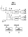
- Fig. 1 shows an electric motor car drive control apparatus according to a relevant art, which includes: a supply line composed of a pantograph 1, a high-speed circuit breaker 2, a charge resistor 3, and a charge resistor short-circuiting contactor 4, and configured to take in electricity from an external dc (direct current) power source; a ground line, with wheels 21 inclusive; two inverter circuits composed of opening contactors 5 and 6, filter reactors 40 and 41, filter capacitors 7 and 8, and VVVF inverters 9 and 10, respectively, and connected in parallel between the supply line and the ground line; two sets of induction motors 28, 29 and 30, 31 to be concurrently driven by the VVVF inverters 9 and 10, respectively; and two gate controllers 26 and 27 adapted for gate control of the VVVF inverters 9 and 10, respectively.
- a supply line composed of a pantograph 1, a high-speed circuit breaker 2, a charge resistor 3, and a charge resistor short-circuiting contactor 4, and configured to take in electricity from an external
- Fig. 2 shows an electric motor car drive control apparatus according to another relevant art, which includes: a supply line composed of a pantograph 1, a high-speed circuit breaker 2, a charge resistor 3, and a charge resistor short-circuiting contactor 4, and configured to take in electricity from an external dc power source: a ground line, with wheels 21 inclusive; a single inverter circuit composed of a filter reactor 42 connected to the supply line, and a combination of a filter capacitor 24 and a VVVF inverter 9 connected in parallel between the filter reactor 42 and the ground line; a set of four induction motors 28, 29, 30, and 31 to be concurrently driven by the VVVF inverter 9; and a gate controller 33 adapted for gate control of the VVVF inverter 9.
- a supply line composed of a pantograph 1, a high-speed circuit breaker 2, a charge resistor 3, and a charge resistor short-circuiting contactor 4, and configured to take in electricity from an external dc power source: a ground line, with wheels
- the induction motors 28, 29, 30, and 31 are now referred to IM(1), IM(2), IM(3), and IM(4), respectively, for better understanding.
- IM(1), IM(2), IM(3), and IM(4) are arranged for a truck control by a control unit of two motors.
- IM(4) are arranged for a centralized control by a control unit of four motors.
- each permanent magnet synchronous motor needs a control with a voltage supplied from a VVVF inverter in accordance with a rotation of the rotor, and it is required to provide a single dedicated VVVF inverter per one motor, to implement a so-called individual control.
- the opening is to be made by a unit of truck, allowing for a so-called individual opening.
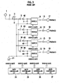
- Fig. 3 shows an electric motor car drive control apparatus in a train drive system having permanent magnetic synchronous motors as drive motors according to another relevant art .
- This electric motor car drive control apparatus includes: a supply line composed of a pantograph 1, a high-speed circuit breaker 2, a charge resistor 3, and a charge resistor short-circuiting contactor 4, and configured to take in electricity from an external dc power source; a ground line, with wheels 21 inclusive: four inverter circuits composed of opening contactors 5, 6, 38, and 39, filter reactors 40, 41, 45, and 46, filter capacitors 7, 8, 43, and 44, and VVVF inverters 9, 10, 11, and 12, respectively, and connected in parallel between the supply line and the ground line; four permanent magnetic synchronous motors 17, 18, 19, and 20 connected through three-phase load contactors 13, 14, 15, and 16 to ac (alternating current) ends of the VVVF inverters 9, 10, 11, and 12, respectively, to be driven by the VVVF inverters 9, 10, 11, and 12, respectively; and four gate controllers
- the present invention has been devised in view of such points in the relevant art. It therefore is an object of the present invention to provide an electric motor car drive control apparatus enabling, in a train drive system having permanent magnetic synchronous motors employed as drive motors, such a configuration that allows, upon a failure of any motor, a similar control to a centralized control like the case of induction motors , unless an individual opening is required for each motor, thus allowing for a reduced cost and a minimized installation size of the system.
- An aspect of the present invention is an electric motor car drive control apparatus which includes a plurality of permanent magnetic synchronous motors provided as car drive motors, a plurality of VVVF inverters adapted to drive the plurality of permanent magnetic synchronous motors in a one-to-one corresponding manner, the plurality of VVVF inverters being grouped into a plurality of control units each respectively composed of two or more VVVF inverters, and a plurality of gate controllers provided one for each control unit.
- the plurality of permanent magnetic synchronous motors can be individually controlled by the plurality of VVVF inverters, respectively, and twos or mores of the plurality of WVF inverters can be each controlled concurrently by a single gate controller, so that a simple provision of gate controllers identical in number to a fraction of division by the number of VVVF inverters of the control unit can do well, without needing an equivalent number of gate controllers to the plurality of VVVF inverters, thus allowing for a decreased cost and a minimized installation size of the system.
- Fig. 4 shows configuration of an electric motor car drive control apparatus according to the first embodiment of the present invention.
- the electric motor car drive control apparatus includes: a supply line composed of a pantograph 1. a high-speed circuit breaker 2, a charge resistor 3, and a charge resistor short-circuiting contactor 4, and configured to take in electricity from an external dc power source; a ground line, with wheels 21 inclusive; two inverter circuits composed of opening contactors 5 and 6, filter reactors 40 and 41, filter capacitors 7 and 8, and two sets of VVVF inverters 9, 10 and 11, 12, respectively, and connected in parallel between the supply line and the ground line; four permanent magnetic synchronous motors 17, 18, 19, and 20 connected through three-phase load contactors 13, 14, 15, and 16 to ac ends of the VVVF inverters 9, 10, 11, and 12, respectively, to be driven by the VVVF inverters 9, 10, 11, and 12, respectively; and two gate controllers 22 and 23 adapted for gate control of the VVVF inverters 9, 10, 11, and 12, by a control
- the gate controllers 22 and 23 , filter capacitors 7 and 8, and combinations of opening contactors 5 and 6 and filter reactors 40 and 41 are common to the sets of VVVF inverters 9, 10 and 11, 12, respectively. It is noted that the gate controllers 22 and 23 have their CPU's (central processing units) adapted for individual control of the sets of VVVF inverters 9, 10 and 11, 12, respectively.
- the gate controller 22 is configured to control both of gates of the set of VVVF inverters 9, 10.
- the gate controller 22 works to open the opening contactor 5 associated with that control unit, thereby stopping two VVVF inverters 9, 10 constituting the control unit, while opening both the permanent magnetic synchronous motors 17, 18.
- the electric motor car drive control apparatus according to this embodiment is adapted for a control to implement a sort of truck opening.
- the present embodiment it is possible to reduce the number of gate controllers, as well as that of opening contactors, to a fraction of division by the number thereof in the control unit, i.e., one half, with respect to that of an electric motor car drive control apparatus employing permanent magnetic synchronous motors according to a relevant art, thus enabling, even for a synchronous motor using permanent magnets, a principal circuit configuration more like to the truck control of induction motors, allowing for a reduced cost and a minimized installation size.
- the gate controllers 22 and 23 have CPU' s employed therefor, which are each able to control a plurality of motors, and adapted in a wheel slip and skid control to achieve a fast recognition of speeds of the four motors, allowing for implementation of a high-speed slip and skid control by an instantaneous detection of speed differences between those motors.
- Fig. 5 shows configuration of an electric motor car drive control apparatus according to the second embodiment of the present invention.
- the electric motor car drive control apparatus includes: a supply line composed of a pantograph 1, a high-speed circuit breaker 2, a charge resistor 3, and a charge resistor short-circuiting contactor 4, and configured to take in electricity from an external dc power source; a ground line, with wheels 21 inclusive; a single inverter circuit composed of a single filter reactor 42 connected to the supply line, and a combination of a single filter capacitor 24 and four VVVF inverters 9, 10, 11, and 12 connected in parallel between the filter reactor 42 and the ground line; four permanent magnetic synchronous motors 17, 18, 19, and 20 connected through three-phase load contactors 13, 14, 15 , and 16 to ac ends of the VVVF inverters 9, 10, 11, and 12, respectively, to be driven by the VVVF inverters 9, 10; 11, and 12, respectively; and a single gate controller 25 adapted for gate control of the VVVF inverters 9, 10, 11, and 12, by a
- the gate controller 25 and the filter capacitor 24 are common to the four VVVF inverters 9 to 12.
- the pantograph 1, high-speed circuit breaker 2, charge resistor 3, and charge resistor short-circuiting contactor 4 are common to the four VVVF inverters 9 to 12, and in this embodiment, also the filter reactor 42 is common. There is no common opening contactor shown in the embodiment of Fig. 5.
- the single gate controller 25 is configured with an incorporated CPU, which is adapted for an individual control of the four VVVF inverters 9 to 12.
- the single gate controller 25 is configured to control the gate of a respective one of four VWF inverters 9 to 12 in the control unit.
- any VVVF inverter in the control unit e.g. the VWF inverter 9 fails, this is followed by control actions to open the whole system in which no opening contactor is provided.
- the electric motor car drive control apparatus is adapted to implement a sort of centralized control.
Landscapes
- Engineering & Computer Science (AREA)
- Power Engineering (AREA)
- Transportation (AREA)
- Mechanical Engineering (AREA)
- Life Sciences & Earth Sciences (AREA)
- Sustainable Development (AREA)
- Sustainable Energy (AREA)
- Electric Propulsion And Braking For Vehicles (AREA)
- Control Of Multiple Motors (AREA)
Abstract
To provide an electric motor car drive control apparatus enabling, in a train drive system having permanent magnetic synchronous motors employed as drive motors, such a configuration that allows a similar control to a centralized control like the case of induction motors, allowing for a reduced cost and a minimized installation size of the system, a plurality of permanent magnetic synchronous motors 17 to 20 are provided as car drive motors, a plurality of VVVF inverters 9 to 12 are adapted to drive the plurality of permanent magnetic synchronous motors individually in a one-to-one corresponding manner, the plurality of VVVF inverters being grouped into a plurality of control units each respectively composed0 of two or more VVVF inverters, and a plurality of gate controllers 22 and 23 are provided one for each control unit.
Description
- The present invention relates to an electric motor car drive control apparatus for controlling a train drive system, which drives a locomotive or a motor railcar, including a plurality of permanent magnet synchronous motors (referred in the drawings to "PMSM") each respectively configured as a drive motor, and a plurality of VVVF (variable voltage variable frequency: referred in the drawings to "VVVF") inverters each respectively adapted for an individual driving of a corresponding permanent magnet synchronous motor.
- According to a relevant art employing induction motors (referred in the drawings to "IM") as drive motors, two or four induction motors are connected in parallel as a control unit to be controlled with a single VVVF inverter. Accordingly, if any induction motor fails, whole induction motors in the control unit where the failing induction motor belongs are opened together with an associated inverter.
- Fig. 1 shows an electric motor car drive control apparatus according to a relevant art, which includes: a supply line composed of a
pantograph 1, a high-speed circuit breaker 2, acharge resistor 3, and a charge resistor short-circuiting contactor 4, and configured to take in electricity from an external dc (direct current) power source; a ground line, withwheels 21 inclusive; two inverter circuits composed ofopening contactors filter reactors VVVF inverters induction motors VVVF inverters gate controllers VVVF inverters - Fig. 2 shows an electric motor car drive control apparatus according to another relevant art, which includes: a supply line composed of a
pantograph 1, a high-speed circuit breaker 2, acharge resistor 3, and a charge resistor short-circuiting contactor 4, and configured to take in electricity from an external dc power source: a ground line, withwheels 21 inclusive; a single inverter circuit composed of afilter reactor 42 connected to the supply line, and a combination of afilter capacitor 24 and aVVVF inverter 9 connected in parallel between thefilter reactor 42 and the ground line; a set of fourinduction motors VVVF inverter 9; and agate controller 33 adapted for gate control of theVVVF inverter 9. - The
induction motors - As shown in
Japanese Patent Application Laid-Open Publication No. 2005-328619 Japanese Patent Application No. 2004-143577 - There is thus needed a configuration for the so-called individual control, where opening contactors for VVVF inverters, as well as gate controllers for gate control of the inverters, should be identical in number to the motors to be controlled, as shown in Fig. 3.
- Fig. 3 shows an electric motor car drive control apparatus in a train drive system having permanent magnetic synchronous motors as drive motors according to another relevant art . This electric motor car drive control apparatus includes: a supply line composed of a
pantograph 1, a high-speed circuit breaker 2, acharge resistor 3, and a charge resistor short-circuiting contactor 4, and configured to take in electricity from an external dc power source; a ground line, withwheels 21 inclusive: four inverter circuits composed ofopening contactors filter reactors filter capacitors VVVF inverters synchronous motors phase load contactors VVVF inverters VVVF inverters gate controllers VVVF inverters 9. 10, 11, and 12, respectively. - Such being the case, in a train drive system having permanent magnetic synchronous motors employed as drive motors according to a relevant art, a configuration for individual control is needed, requiring opening contactors for VVVF inverters, as well as gate controllers for gate control of the inverters, to be identical in number to the motors, with an increased cost and an enlarged installation size, as a problem.
- The present invention has been devised in view of such points in the relevant art. It therefore is an object of the present invention to provide an electric motor car drive control apparatus enabling, in a train drive system having permanent magnetic synchronous motors employed as drive motors, such a configuration that allows, upon a failure of any motor, a similar control to a centralized control like the case of induction motors , unless an individual opening is required for each motor, thus allowing for a reduced cost and a minimized installation size of the system.
- An aspect of the present invention is an electric motor car drive control apparatus which includes a plurality of permanent magnetic synchronous motors provided as car drive motors, a plurality of VVVF inverters adapted to drive the plurality of permanent magnetic synchronous motors in a one-to-one corresponding manner, the plurality of VVVF inverters being grouped into a plurality of control units each respectively composed of two or more VVVF inverters, and a plurality of gate controllers provided one for each control unit.
- According to the electric motor car drive control apparatus of this invention, the plurality of permanent magnetic synchronous motors can be individually controlled by the plurality of VVVF inverters, respectively, and twos or mores of the plurality of WVF inverters can be each controlled concurrently by a single gate controller, so that a simple provision of gate controllers identical in number to a fraction of division by the number of VVVF inverters of the control unit can do well, without needing an equivalent number of gate controllers to the plurality of VVVF inverters, thus allowing for a decreased cost and a minimized installation size of the system.
-
- Fig. 1 is a block diagram of an electric motor car drive control apparatus configured for a truck control of induction motors according to a relevant art.
- Fig. 2 is a block diagram of an electric motor car drive control apparatus configured for a centralized control of induction motors according to another relevant art.
- Fig. 31s a block diagram of an electric motor car drive control apparatus of an electric motor car drive system configured with permanent magnet synchronous motors according to another relevant art.
- Fig. 4 is a block diagram of an electric motor car drive control apparatus according to a first embodiment of the present invention.
- Fig. 5 is a block diagram of an electric motor car drive control apparatus according to a second embodiment of the present invention.
- There will be described below the preferred embodiments of the present invention into details with reference to the accompanying drawings. Like members or elements will be designated by like reference characters.
- Fig. 4 shows configuration of an electric motor car drive control apparatus according to the first embodiment of the present invention. In this embodiment, the electric motor car drive control apparatus includes: a supply line composed of a
pantograph 1. a high-speed circuit breaker 2, acharge resistor 3, and a charge resistor short-circuiting contactor 4, and configured to take in electricity from an external dc power source; a ground line, withwheels 21 inclusive; two inverter circuits composed ofopening contactors filter reactors VVVF inverters synchronous motors phase load contactors VVVF inverters VVVF inverters gate controllers VVVF inverters gate controllers opening contactors filter reactors VVVF inverters gate controllers VVVF inverters - In the above-noted electric motor car drive control apparatus, the
gate controller 22 is configured to control both of gates of the set ofVVVF inverters gate controller 22 works to open theopening contactor 5 associated with that control unit, thereby stopping twoVVVF inverters synchronous motors - According to the present embodiment, it is possible to reduce the number of gate controllers, as well as that of opening contactors, to a fraction of division by the number thereof in the control unit, i.e., one half, with respect to that of an electric motor car drive control apparatus employing permanent magnetic synchronous motors according to a relevant art, thus enabling, even for a synchronous motor using permanent magnets, a principal circuit configuration more like to the truck control of induction motors, allowing for a reduced cost and a minimized installation size.
- It is noted that in the present embodiment the
gate controllers - Fig. 5 shows configuration of an electric motor car drive control apparatus according to the second embodiment of the present invention. In this embodiment, the electric motor car drive control apparatus includes: a supply line composed of a
pantograph 1, a high-speed circuit breaker 2, acharge resistor 3, and a charge resistor short-circuiting contactor 4, and configured to take in electricity from an external dc power source; a ground line, withwheels 21 inclusive; a single inverter circuit composed of asingle filter reactor 42 connected to the supply line, and a combination of asingle filter capacitor 24 and fourVVVF inverters filter reactor 42 and the ground line; four permanent magneticsynchronous motors phase load contactors VVVF inverters VVVF inverters single gate controller 25 adapted for gate control of theVVVF inverters gate controller 25 and thefilter capacitor 24 are common to the fourVVVF inverters 9 to 12. In this embodiment also, thepantograph 1, high-speed circuit breaker 2,charge resistor 3, and charge resistor short-circuiting contactor 4 are common to the fourVVVF inverters 9 to 12, and in this embodiment, also thefilter reactor 42 is common. There is no common opening contactor shown in the embodiment of Fig. 5. - In the present embodiment, the
single gate controller 25 is configured with an incorporated CPU, which is adapted for an individual control of the fourVVVF inverters 9 to 12. - In the electric motor car drive control apparatus according to this embodiment, the
single gate controller 25 is configured to control the gate of a respective one of fourVWF inverters 9 to 12 in the control unit. In this case, if any VVVF inverter in the control unit, e.g. theVWF inverter 9, fails, this is followed by control actions to open the whole system in which no opening contactor is provided. In other words, in this embodiment, the electric motor car drive control apparatus is adapted to implement a sort of centralized control. - According to this embodiment of electric motor car drive control apparatus, it is possible to reduce the number of gate controllers to a quarter of that in a relevant art, thus enabling, even for a synchronous motor using permanent magnets, a main circuit configuration more like to the centralized control of induction motors, allowing for a reduced cost and a minimized installation size.
- While preferred embodiments of the present invention have been described using specific terms, such description is for illustrative purposes, and it is to be understood that changes and variations may be made without departing from the scope of the following claims.
Claims (4)
- An electric motor car drive control apparatus comprising:a plurality of permanent magnetic synchronous motors provided as car drive motors;a plurality of VVVF inverters adapted to drive the plurality of permanent magnetic synchronous motors individually in a one-to-one corresponding manner, the plurality of VVVF inverters being grouped into a plurality of control units each respectively composed of two or more VVVF inverters; anda plurality of gate controllers provided one for each control unit.
- The electric motor car drive control apparatus as claimed in claim 1, further comprising a plurality of inverter opening contactors provided one for each control unit of VVVF inverters, and each respectively adapted for a concurrent opening from power supply of a corresponding control unit of VVVF inverters.
- The electric motor car drive control apparatus as claimed in claim 1, wherein the plurality of VVVF inverters are grouped into a plurality of control units each respectively composed of two VVVF inverters.
- The electric motor car drive control apparatus as claimed in claim 1, wherein the plurality of WVF inverters are grouped into a plurality of control units each respectively composed of four VVVF inverters.
Applications Claiming Priority (1)
| Application Number | Priority Date | Filing Date | Title |
|---|---|---|---|
| JP2006185555A JP2008017609A (en) | 2006-07-05 | 2006-07-05 | Electric vehicle control device |
Publications (1)
| Publication Number | Publication Date |
|---|---|
| EP1876052A2 true EP1876052A2 (en) | 2008-01-09 |
Family
ID=38577453
Family Applications (1)
| Application Number | Title | Priority Date | Filing Date |
|---|---|---|---|
| EP07012997A Withdrawn EP1876052A2 (en) | 2006-07-05 | 2007-07-03 | Electric motor car drive control apparatus |
Country Status (5)
| Country | Link |
|---|---|
| US (1) | US20080129231A1 (en) |
| EP (1) | EP1876052A2 (en) |
| JP (1) | JP2008017609A (en) |
| KR (1) | KR20080004400A (en) |
| CN (1) | CN101100173A (en) |
Families Citing this family (8)
| Publication number | Priority date | Publication date | Assignee | Title |
|---|---|---|---|---|
| JP4625147B2 (en) * | 2009-04-13 | 2011-02-02 | パナソニック株式会社 | Synchronous motor drive system |
| JP5404310B2 (en) * | 2009-10-27 | 2014-01-29 | 株式会社東芝 | Power supply |
| JP5875214B2 (en) * | 2010-03-17 | 2016-03-02 | 富士電機株式会社 | Power conversion system |
| WO2011125784A1 (en) | 2010-03-31 | 2011-10-13 | 株式会社 東芝 | Electric vehicle control device |
| DE102012222691A1 (en) * | 2012-12-11 | 2014-06-12 | Siemens Aktiengesellschaft | Drive device for a vehicle |
| WO2014136271A1 (en) * | 2013-03-08 | 2014-09-12 | 株式会社東芝 | Power converter for vehicle |
| CN106541839A (en) * | 2016-10-25 | 2017-03-29 | 中车永济电机有限公司 | A kind of high-power density permanent magnetic synchronization metro traction system |
| US11518247B2 (en) * | 2017-12-28 | 2022-12-06 | Mitsubishi Electric Corporation | Electric vehicle controller |
Family Cites Families (14)
| Publication number | Priority date | Publication date | Assignee | Title |
|---|---|---|---|---|
| JPH0515012A (en) * | 1991-06-28 | 1993-01-22 | Toshiba Corp | Controlling method for individual axle of electric motor vehicle |
| JP3124143B2 (en) * | 1993-01-20 | 2001-01-15 | 株式会社東芝 | Inverter device |
| JPH0835713A (en) * | 1994-07-26 | 1996-02-06 | Fujitsu General Ltd | Air conditioner control method and device |
| JP2000188803A (en) * | 1998-12-22 | 2000-07-04 | Toshiba Corp | Electric car control device |
| JP3884909B2 (en) * | 2000-12-06 | 2007-02-21 | 株式会社日立製作所 | Electric vehicle and its control device |
| JP4559665B2 (en) * | 2001-06-29 | 2010-10-13 | 株式会社東芝 | Electric motor drive control device |
| WO2003056694A1 (en) * | 2001-12-26 | 2003-07-10 | Toyota Jidosha Kabushiki Kaisha | Electrical load apparatus, electrical load control method, and computer-readable record medium with recorded program for enabling computer to control electrical load |
| JP2004166447A (en) * | 2002-11-15 | 2004-06-10 | Toshiba Corp | Power converter for electric vehicles |
| JP3661689B2 (en) * | 2003-03-11 | 2005-06-15 | トヨタ自動車株式会社 | Motor drive device, hybrid vehicle drive device including the same, and computer-readable recording medium storing a program for causing a computer to control the motor drive device |
| JP4474898B2 (en) * | 2003-10-23 | 2010-06-09 | トヨタ自動車株式会社 | Motor drive device |
| JP4001120B2 (en) * | 2004-02-19 | 2007-10-31 | トヨタ自動車株式会社 | Voltage converter |
| JP4610950B2 (en) * | 2004-07-06 | 2011-01-12 | 株式会社日立製作所 | Train control method and railway vehicle control apparatus |
| JP4254693B2 (en) * | 2004-11-08 | 2009-04-15 | トヨタ自動車株式会社 | Driving device and automobile equipped with the same |
| US7733039B2 (en) * | 2006-10-19 | 2010-06-08 | Ut-Battelle, Llc | Electric vehicle system for charging and supplying electrical power |
-
2006
- 2006-07-05 JP JP2006185555A patent/JP2008017609A/en active Pending
-
2007
- 2007-07-03 EP EP07012997A patent/EP1876052A2/en not_active Withdrawn
- 2007-07-04 KR KR1020070067233A patent/KR20080004400A/en not_active Ceased
- 2007-07-05 CN CNA2007101274583A patent/CN101100173A/en active Pending
- 2007-07-05 US US11/773,695 patent/US20080129231A1/en not_active Abandoned
Also Published As
| Publication number | Publication date |
|---|---|
| JP2008017609A (en) | 2008-01-24 |
| US20080129231A1 (en) | 2008-06-05 |
| KR20080004400A (en) | 2008-01-09 |
| CN101100173A (en) | 2008-01-09 |
Similar Documents
| Publication | Publication Date | Title |
|---|---|---|
| EP1876052A2 (en) | Electric motor car drive control apparatus | |
| CN108365767B (en) | Electrical structure for converting DC voltage to AC voltage and vice versa and method thereof | |
| CN101682277A (en) | Motor control device | |
| CN1090837C (en) | Reduction operation for multi-winding induction motor after fault of converter | |
| EP3151396B1 (en) | Rotary electric machine controller and system | |
| US20150364978A1 (en) | Electric Machine | |
| JP2001157487A (en) | Control device for rotating electric machine | |
| JP2000245005A (en) | Vehicle drive control device | |
| US11050373B2 (en) | Rotary electric system | |
| CN103368478A (en) | Control device for rotating electrical machine | |
| JP2009072049A (en) | Electric vehicle control device | |
| CN111082415A (en) | Power supply to AC loads during a power source failure in an elevator system | |
| CN104767463B (en) | A kind of motor driver with fault tolerance | |
| US20100148717A1 (en) | Asynchronous AC induction electrical machines in cross-interlockingly parallel connection | |
| CN103507660B (en) | For driving the method for electric traction drive system | |
| CN114123706A (en) | A linear motor transport system | |
| CN106740258A (en) | Magnetic-levitation train linear electric motors power supply circuit and method | |
| CN110603168B (en) | Railway vehicle | |
| US10855218B2 (en) | Electronic pole changing-based induction motor control system and control method thereof | |
| EP2793385B1 (en) | Electric power conversion device | |
| CN110492825A (en) | Delivery system | |
| JP2012075317A (en) | Electric vehicle controller | |
| CN101192802A (en) | Spinning machine with electric drive | |
| CN102774292A (en) | Dual-motor drive system | |
| JP2004104973A (en) | Inverter control device |
Legal Events
| Date | Code | Title | Description |
|---|---|---|---|
| PUAI | Public reference made under article 153(3) epc to a published international application that has entered the european phase |
Free format text: ORIGINAL CODE: 0009012 |
|
| 17P | Request for examination filed |
Effective date: 20070703 |
|
| AK | Designated contracting states |
Kind code of ref document: A2 Designated state(s): AT BE BG CH CY CZ DE DK EE ES FI FR GB GR HU IE IS IT LI LT LU LV MC MT NL PL PT RO SE SI SK TR |
|
| AX | Request for extension of the european patent |
Extension state: AL BA HR MK YU |
|
| STAA | Information on the status of an ep patent application or granted ep patent |
Free format text: STATUS: THE APPLICATION HAS BEEN WITHDRAWN |
|
| 18W | Application withdrawn |
Effective date: 20140116 |