EP1875321B1 - Flow control - Google Patents
Flow control Download PDFInfo
- Publication number
- EP1875321B1 EP1875321B1 EP20060726924 EP06726924A EP1875321B1 EP 1875321 B1 EP1875321 B1 EP 1875321B1 EP 20060726924 EP20060726924 EP 20060726924 EP 06726924 A EP06726924 A EP 06726924A EP 1875321 B1 EP1875321 B1 EP 1875321B1
- Authority
- EP
- European Patent Office
- Prior art keywords
- fluid
- reservoir
- sample channel
- channel
- syphon
- Prior art date
- Legal status (The legal status is an assumption and is not a legal conclusion. Google has not performed a legal analysis and makes no representation as to the accuracy of the status listed.)
- Not-in-force
Links
Images


Classifications
-
- G—PHYSICS
- G05—CONTROLLING; REGULATING
- G05D—SYSTEMS FOR CONTROLLING OR REGULATING NON-ELECTRIC VARIABLES
- G05D11/00—Control of flow ratio
- G05D11/02—Controlling ratio of two or more flows of fluid or fluent material
- G05D11/13—Controlling ratio of two or more flows of fluid or fluent material characterised by the use of electric means
- G05D11/135—Controlling ratio of two or more flows of fluid or fluent material characterised by the use of electric means by sensing at least one property of the mixture
- G05D11/138—Controlling ratio of two or more flows of fluid or fluent material characterised by the use of electric means by sensing at least one property of the mixture by sensing the concentration of the mixture, e.g. measuring pH value
-
- A—HUMAN NECESSITIES
- A61—MEDICAL OR VETERINARY SCIENCE; HYGIENE
- A61L—METHODS OR APPARATUS FOR STERILISING MATERIALS OR OBJECTS IN GENERAL; DISINFECTION, STERILISATION OR DEODORISATION OF AIR; CHEMICAL ASPECTS OF BANDAGES, DRESSINGS, ABSORBENT PADS OR SURGICAL ARTICLES; MATERIALS FOR BANDAGES, DRESSINGS, ABSORBENT PADS OR SURGICAL ARTICLES
- A61L2/00—Methods or apparatus for disinfecting or sterilising materials or objects other than foodstuffs or contact lenses; Accessories therefor
- A61L2/16—Methods or apparatus for disinfecting or sterilising materials or objects other than foodstuffs or contact lenses; Accessories therefor using chemical substances
- A61L2/18—Liquid substances or solutions comprising solids or dissolved gases
-
- A—HUMAN NECESSITIES
- A61—MEDICAL OR VETERINARY SCIENCE; HYGIENE
- A61L—METHODS OR APPARATUS FOR STERILISING MATERIALS OR OBJECTS IN GENERAL; DISINFECTION, STERILISATION OR DEODORISATION OF AIR; CHEMICAL ASPECTS OF BANDAGES, DRESSINGS, ABSORBENT PADS OR SURGICAL ARTICLES; MATERIALS FOR BANDAGES, DRESSINGS, ABSORBENT PADS OR SURGICAL ARTICLES
- A61L2/00—Methods or apparatus for disinfecting or sterilising materials or objects other than foodstuffs or contact lenses; Accessories therefor
- A61L2/24—Apparatus using programmed or automatic operation
-
- B—PERFORMING OPERATIONS; TRANSPORTING
- B08—CLEANING
- B08B—CLEANING IN GENERAL; PREVENTION OF FOULING IN GENERAL
- B08B9/00—Cleaning hollow articles by methods or apparatus specially adapted thereto
- B08B9/02—Cleaning pipes or tubes or systems of pipes or tubes
- B08B9/027—Cleaning the internal surfaces; Removal of blockages
- B08B9/032—Cleaning the internal surfaces; Removal of blockages by the mechanical action of a moving fluid, e.g. by flushing
-
- G—PHYSICS
- G01—MEASURING; TESTING
- G01N—INVESTIGATING OR ANALYSING MATERIALS BY DETERMINING THEIR CHEMICAL OR PHYSICAL PROPERTIES
- G01N35/00—Automatic analysis not limited to methods or materials provided for in any single one of groups G01N1/00 - G01N33/00; Handling materials therefor
- G01N35/10—Devices for transferring samples or any liquids to, in, or from, the analysis apparatus, e.g. suction devices, injection devices
- G01N35/1095—Devices for transferring samples or any liquids to, in, or from, the analysis apparatus, e.g. suction devices, injection devices for supplying the samples to flow-through analysers
- G01N35/1097—Devices for transferring samples or any liquids to, in, or from, the analysis apparatus, e.g. suction devices, injection devices for supplying the samples to flow-through analysers characterised by the valves
-
- A—HUMAN NECESSITIES
- A61—MEDICAL OR VETERINARY SCIENCE; HYGIENE
- A61L—METHODS OR APPARATUS FOR STERILISING MATERIALS OR OBJECTS IN GENERAL; DISINFECTION, STERILISATION OR DEODORISATION OF AIR; CHEMICAL ASPECTS OF BANDAGES, DRESSINGS, ABSORBENT PADS OR SURGICAL ARTICLES; MATERIALS FOR BANDAGES, DRESSINGS, ABSORBENT PADS OR SURGICAL ARTICLES
- A61L2202/00—Aspects relating to methods or apparatus for disinfecting or sterilising materials or objects
- A61L2202/10—Apparatus features
- A61L2202/14—Means for controlling sterilisation processes, data processing, presentation and storage means, e.g. sensors, controllers, programs
-
- A—HUMAN NECESSITIES
- A61—MEDICAL OR VETERINARY SCIENCE; HYGIENE
- A61L—METHODS OR APPARATUS FOR STERILISING MATERIALS OR OBJECTS IN GENERAL; DISINFECTION, STERILISATION OR DEODORISATION OF AIR; CHEMICAL ASPECTS OF BANDAGES, DRESSINGS, ABSORBENT PADS OR SURGICAL ARTICLES; MATERIALS FOR BANDAGES, DRESSINGS, ABSORBENT PADS OR SURGICAL ARTICLES
- A61L2202/00—Aspects relating to methods or apparatus for disinfecting or sterilising materials or objects
- A61L2202/10—Apparatus features
- A61L2202/17—Combination with washing or cleaning means
-
- Y—GENERAL TAGGING OF NEW TECHNOLOGICAL DEVELOPMENTS; GENERAL TAGGING OF CROSS-SECTIONAL TECHNOLOGIES SPANNING OVER SEVERAL SECTIONS OF THE IPC; TECHNICAL SUBJECTS COVERED BY FORMER USPC CROSS-REFERENCE ART COLLECTIONS [XRACs] AND DIGESTS
- Y10—TECHNICAL SUBJECTS COVERED BY FORMER USPC
- Y10T—TECHNICAL SUBJECTS COVERED BY FORMER US CLASSIFICATION
- Y10T137/00—Fluid handling
- Y10T137/0318—Processes
- Y10T137/0324—With control of flow by a condition or characteristic of a fluid
-
- Y—GENERAL TAGGING OF NEW TECHNOLOGICAL DEVELOPMENTS; GENERAL TAGGING OF CROSS-SECTIONAL TECHNOLOGIES SPANNING OVER SEVERAL SECTIONS OF THE IPC; TECHNICAL SUBJECTS COVERED BY FORMER USPC CROSS-REFERENCE ART COLLECTIONS [XRACs] AND DIGESTS
- Y10—TECHNICAL SUBJECTS COVERED BY FORMER USPC
- Y10T—TECHNICAL SUBJECTS COVERED BY FORMER US CLASSIFICATION
- Y10T137/00—Fluid handling
- Y10T137/0318—Processes
- Y10T137/0396—Involving pressure control
-
- Y—GENERAL TAGGING OF NEW TECHNOLOGICAL DEVELOPMENTS; GENERAL TAGGING OF CROSS-SECTIONAL TECHNOLOGIES SPANNING OVER SEVERAL SECTIONS OF THE IPC; TECHNICAL SUBJECTS COVERED BY FORMER USPC CROSS-REFERENCE ART COLLECTIONS [XRACs] AND DIGESTS
- Y10—TECHNICAL SUBJECTS COVERED BY FORMER USPC
- Y10T—TECHNICAL SUBJECTS COVERED BY FORMER US CLASSIFICATION
- Y10T137/00—Fluid handling
- Y10T137/8593—Systems
- Y10T137/85978—With pump
- Y10T137/86083—Vacuum pump
Definitions
- the present invention relates to a method and apparatus for controlling the flow of fluids through a sample channel.
- the invention has particularly application in medical facilities for measuring or verifying the concentration of an active component of a sterilizing fluid.
- Chlorine dioxide (ClO 2 ) is an important sterilizing agent in medical facilities such as surgeries and hospitals. It is used for sterilizing medical and dental equipment or for wound irrigation or skin asepsis.
- the apparatus disclosed in W02005/011759 uses a probe capable of directly measuring concentrations of ClO 2 (the active component of the sterilizing fluid) in the range 1-20 ppm.
- probes for directly measuring higher ClO 2 concentrations tend to be far more sensitive and are damaged by prolonged exposure to such high concentrations of ClO 2 . Therefore, indirect techniques are used to measure concentrations of ClO 2 in excess of 20 ppm. These indirect techniques involve measuring a diluted sample of the ClO 2 -dosed sterilizing fluid 11, and using an algorithm to calculate the concentration of the original sample.
- DE3400263 discloses a device for monitoring the concentration at which disinfectant solutions are prepared from water and concentrated disinfectant by means of a metering device.
- the device has a conductivity-measuring probe immersed in the disinfectant solution. Electrical signals from the probe are supplied to an evaluation device with which the conductivity is monitored as a measure of the concentration being used.
- a probe is located within the sample channel.
- the term 'probe' is intended to be construed broadly, and to mean anything that is capable of detecting or measuring a property of a fluid.
- the term 'sample channel' is also intended to be construed broadly, and to include any fluid carrying channel in which flow control as described above is achieved. It is not essential that measurements are taken in the sample channel.
- the probe is used to measure the concentration of a component of the first fluid
- the apparatus preferably comprises processing means for converting the probe reading to a concentration value.
- Concentration measuring probes tend to require contact with the analyte for an extended period of time before an accurate and stable concentration measurement is obtained. This time period is often of the order of minutes. Ensuring fluid from the reservoir flows past the probe for a number of minutes could require having a large reservoir capable of containing a large volume of fluid. Preferably, however, a return channel is connected between the sample channel and the reservoir to form a recirculation loop. Fluid from the reservoir may circulate around the loop and past the probe a number of times for a predetermined time period long enough for the probe to take an accurate and stable reading. Preferably, this predetermined time period is around two minutes.
- the second fluid is used to flush out the system after the probe has been in contact with the first fluid.
- the second fluid is preferably a neutral fluid, and most preferably is water.
- the apparatus is particularly suitable for use in hospitals or dental practices, and may be connected to the hospital's or dental practice's regular supply of tap water.
- deionised water is used to set the zero level of the probe.
- the second fluid is preferably pumped through the sample channel and through the return channel into the reservoir to clean the reservoir before filling with the first fluid.
- the system may, however, comprise a plurality of separate inlets for the second fluid so that the various parts of the system may be flushed with second fluid from various sources.
- the pump means comprises a single pump for pumping fluid out of the reservoir, through the sample channel, back to the reservoir, and out to waste.
- a plurality of pumps may however be used instead to separately perform the various pumping tasks.
- the apparatus may include means for selectively allowing fluid to enter the sample channel or the reservoir.
- these means include solenoid valves, however other types of switchable valves could also be used.
- the means for trapping fluid in the sample channel also preferably comprises two solenoid valves, with the fluid being trapped therebetween.
- the reservoir has a removable lid.
- a duckbilled valve is preferably located near the top of the reservoir for example in the reservoir lid for admitting air into the reservoir when fluid is pumped from the reservoir. This eases the pumping process, and prevents the pump having to pump against a vacuum. Additionally, the duckbilled valve prevents liquid spilling out of the top of the reservoir if the reservoir is overfilled.
- the apparatus is designed to be compatible with many different types of devices. These devices are typically devices for cleaning medical equipment, each of which operates at a different flow rate and pressure.
- the reservoir will therefore be subject to different fill rates depending upon the device it is incorporated within.
- the reservoir preferably includes means for controlling the level of fluid in the reservoir to prevent the reservoir from overflowing, for example an overflow outlet.
- sensing means can be included to sense when a predefined maximum fill level is achieved.
- the apparatus may be configured such that the solenoid valves prevent additional fluid entering the reservoir when the maximum fill level is reached.
- the syphon preferably comprises concentric inner and outer cylinders. It is preferable that the height of the inner cylinder is substantially equal to or greater than the maximum fill level of the reservoir. This arrangement is a safety feature, and ensures that in the event that the airlock in the syphon fails unexpectedly, fluid in the reservoir cannot spill over the inner cylinder walls and enter the sample channel.
- the method includes the step of checking the measured concentration to determine whether or not it is within a predetermined tolerance of the desired concentration.
- Display means may be used to indicate a 'pass' or 'fail' depending on whether the concentration is within the tolerance or not.
- the display means could be a display screen or a ticket could be printed.
- the invention is now described for convenience in relation to an apparatus and method for measuring the concentration of ClO 2 in a sterilizing fluid, the apparatus comprising means for controlling the flow of two fluids. It should be understood this is one particular example of an application of the invention, and that the invention may have application in any field where it is necessary to control the flow of at least two fluids through a single channel whilst keeping the fluids separate and therefore preventing the fluids from mixing.
- apparatus for measuring the concentration of a ClO 2 -dosed sample of sterilizing fluid.
- the apparatus includes a reservoir 10 containing sterilizing fluid 11, and having a reservoir inlet 12 and a reservoir outlet 14.
- the reservoir inlet 12 is connected to a ClO 2 -dosed sample supply line 16 having a ClO 2 inlet 18 for connection to a source of ClO 2 -dosed sterilizing fluid 11.
- a first solenoid valve 17 for selectively allowing ClO 2 -dosed sterilizing fluid 11 into the reservoir 10 is disposed in sample supply line 16 upstream of the reservoir inlet 12
- the reservoir outlet 14 is connected to a sample channel 20.
- a probe 22 for measuring the concentration of ClO 2 in the sterilizing fluid 11 is located in the sample channel 20.
- a pump 24 is also located in the sample channel 20, and is used for pumping fluid through the sample channel 20.
- the pump 24 is a KNF pump which has a 6 Bar (0.6 MPa) pressure rating.
- the sample channel 20 has a sample -channel inlet 28 for connection to a source of water.
- a second solenoid valve 30 is provided in the sample channel 20, downstream of the sample channel inlet 28 for selectively allowing water to flow through the sample channel 20.
- the second solenoid valve could equally usefully be located upstream of the sample channel inlet 28 instead.
- a syphon 32 is connected between the reservoir 10 and the sample channel 20.
- the syphon 32 is located within the reservoir 10 between the fluid 11 and the reservoir outlet 14, such that the fluid in the reservoir must flow through the syphon 32 to reach the reservoir outlet 14.
- the syphon 32 comprises an inner cylinder 36 and an outer cylinder 38.
- the lower end 40 of the inner cylinder 36 surrounds the reservoir outlet 14, and has side walls 42 which extend upwards towards the top of the reservoir 10.
- the inner cylinder 36 has an open top end 44.
- the outer cylinder 38 surrounds the inner cylinder 36.
- the outer cylinder is upturned and has a sealed top end 46 which is located near the top of the reservoir.
- the outer cylinder 38 has an open bottom end 48 which is located near the reservoir outlet 14.
- the outer cylinder 38 has side walls 50 extending from the top of the reservoir 10 towards the bottom of the reservoir 10.
- a reservoir check valve 54 is located outside the reservoir 10 adjacent the reservoir outlet 14.
- the reservoir check valve 54 is a one way valve and prevents fluid from entering the reservoir through the reservoir outlet 14.
- the embodiment of the invention illustrated in Figure 1 also includes a return channel 56.
- One end of the return channel 56 is connected to the sample channel 20 downstream of the pump 24.
- the other end of the return channel 56 feeds into the reservoir 10.
- the return channel 56 is used for carrying fluid from the sample channel 20 to the reservoir 10.
- a third solenoid valve 58 is located at the junction between the sample channel 20 and the return channel 56.
- the third solenoid valve 58 is used for directing fluid in the -sample channel 20 either through the return channel 56 and into the reservoir 10, or through a waste outlet pipe 60.
- An overflow outlet 62 is located in the reservoir 10 to prevent the tank from overflowing.
- a waste channel 64 connects the overflow outlet 62 to the waste outlet pipe 60.
- a waste check valve 66 is located in the waste channel 64 for preventing fluid passing from the waste channel 64 into the reservoir 10.
- Dosed sterilizing fluid 11 from a dosed sterilizing fluid generator enters the reservoir 10 through the reservoir inlet 12. Flow through the reservoir inlet 12 is controlled by the first solenoid valve 17. In this example, the reservoir 10 holds about 100 ml of dosed sterili-zing fluid 11. Surplus dosed sterilizing fluid 11 escapes out of the reservoir 10 through the overflow outlet 62.
- the waste check valve 66 in the waste outlet pipe 64 ensures that liquid can only pass out of, and not into, the reservoir through the waste outlet.
- Undosed water enters the system through the water inlet 28.
- the water inlet 28 is controlled by the second solenoid valve 30. This water is used to flush the reservoir 10, pump 24 and probe 22 to remove traces of ClO 2 .
- the pump 24 and probe 22 are connected to the reservoir outlet 14.
- the reservoir check valve 54 ensures that liquid can only be pumped out of, and not into, the reservoir 10.
- the reservoir outlet 14 is separated from the liquid in the reservoir by the syphon 32. Unless liquid is being pumped out of the reservoir 10, the syphon 32 is filled with air and forms an air lock that separates the contents of the reservoir 10 from the sample channel 20.
- the third solenoid valve 58 controls the flow of fluid from the pump 24. Fluid can either be pumped through the return channel 56 and up to the reservoir 10, or out to the waste outlet pipe 60.
- the first solenoid valve 17 is opened and dosed sterilizing fluid 11 is admitted into the reservoir 10.
- the fill rate depends upon the system flow rate and pressure, and this is generally controlled by the device receiving the dosed sterilizing fluid 11.
- the system is suitable for use in a range of devices for cleaning endoscopes or other medical equipment. These devices tend to operate at different pressures and flow rates depending on the device type and manufacturer.
- Typical line pressures for these devices are in the range 1.03-4.14 bar (15-60 psi), and typical flow rates are in the range 3-20 litres/minute.
- the overflow outlet 62 enables the system to adapt to such different supply pressures and flow rates. Excess of dosed sterilizing fluid 11 flows through the overflow outlet 62 to waste. Preferably, however, the reservoir 10 is filled with at least about 40 ml of dosed sterilizing fluid 11, and wastage is minimised by ensuring that no more than about 100 ml enters the reservoir 10.
- the first solenoid valve 17 is opened for a sufficient period of time to fill the reservoir 10 with at least 40 ml of dosed sterilizing fluid 11.
- the flow rate and pressure varies with application, so a minimum time can be set in which the first solenoid valve 17 remains open to ensure at least 40 ml enters the reservoir 10, or the time in which the first solenoid valve 17 remains open can be changed to suit the application.
- the third solenoid valve 58 is set to allow fluid to be pumped up to the reservoir 10.
- the pump 24 is activated to perform the pumping. Air in the syphon 32 is drawn through the pump 24 and probe 22. When the air in the syphon 32 has been evacuated, dosed sterilizing fluid 11 is drawn through the pump 24 and probe 22 and is pumped back up to the reservoir 10 through the return channel 56. Dosed sterilizing fluid 11 is circulated for two minutes to allow the probe 22 to measure the ClO 2 concentration and provide a stable result.
- the flow rate is determined by the recommended flow rate across the probe 22 which is defined by the probe manufacturer, but is typically in the range 100 - 200 ml/minute.
- a pump such as a KNF (RTM) diaphragm pump, may be used which operates at a flow rate of 100-150 ml/minute at 24 volts.
- the third solenoid valve 58 is set to allow liquid to be pumped to waste.
- the contents of the reservoir 10 are pumped to waste.
- the second solenoid valve 30 is opened to allow water into the sample channel 20.
- the third solenoid valve 58 is set to direct fluid to waste and prevent fluid from passing up to the reservoir 10.
- the pump 24 is used to pump water through the sample channel 20 and through the probe 22 to waste.
- Stage 5 Flush the reservoir and syphon tubes
- the third solenoid valve 58 is set to allow water to be pumped up to the reservoir 10.
- the reservoir 10 is filled with water and allowed to overflow through the overflow outlet 62, through the waste channel 64 and waste check valve 66 to waste.
- the second solenoid valve 30 is closed and the third solenoid valve 58 is opened to direct water from the reservoir 10 to waste.
- the pump 24 is activated to pump the contents of the reservoir 10 to waste for one minute, or for a time period long enough to ensure that the reservoir 10 is completely emptied.
- the third solenoid valve 58 is set to direct fluid to the reservoir 10.
- the pump 24 is activated to pump a slug of water in the return channel 56 into the reservoir 10.
- the third solenoid valve 58 is then set to direct fluid to waste, and the pump 24 is activated to pump the slug of water out of the reservoir 10 to waste.
- all of the system tubes are empty.
- Stage 8 Ensure probe is left immersed in plain water
- the second solenoid valve 28 is opened and water is flushed through the pump 24 and the probe 22 to waste.
- the pump 24 is stopped, and the second solenoid valve 28 is closed.
- the third solenoid valve 58 is set to direct water to the reservoir 10. Since the pump is not activated at this stage, and the second solenoid valve 28 is close, water does not pass into the reservoir 10 through the return channel 56. Instead, the water is trapped in the sample channel 20, which leaves the probe 22 immersed in water.
- the reservoir 10 is now empty and ready for the next refill and sample cycle to begin.
- the consistency of the measured result is influenced by the agitation of the fluid through the pump.
- the exemplified system uses a consistent agitation and produces very consistent results.
- a chlorine dioxide generator incorporating the apparatus of Figure 1 is illustrated schematically in the flow sheet of Figure 11 .
- the generator is suitable for producing a stream of aqueous chlorine dioxide (ClO 2 ) sterilizing fluid for use in sterilizing medical and dental instruments or for wound irrigation or skin asepsis.
- the -concentration of ClO 2 will be varied according the intended application.
- the method of generating ClO 2 is similar to that described in WO2005/011759 A1 with respect to Figure 5 therein.
- the apparatus comprises a first pump connected to a source of base and a second pump connected to a source of activator.
- the therms 'base' and 'activator' are used herein to refer to fluids which when mixed react to produce aqueous ClO 2 .
- the reaction mixture preferably has a pH in the range 4.5 to 6.5, notably 5.5 to 6.5.
- the base and activator are comprised as set forth in Example 3 of US 5,696,046 .
- each pump connects to the proximal end of a tubular helical coil (ClO 2 mixing coil) which functions as an elongate reaction chamber.
- a tubular helical coil ClO 2 mixing coil
- reaction mixture is pumped progressively through the mixing coil to the distal end of the coil.
- the reaction mixture passes from through the mixing coil in about 30 seconds, during which time the reaction to form ClO 2 is substantially complete.
- the reaction mixture is injected into a conduit through which passes a stream of water.
- the reaction mixture mixes with the water to form a stream of aqueous ClO 2 sterilizing fluid.
- the concentration of ClO 2 in the sterilizing fluid can, in this example, be varied between about 20 ppm and about 200 ppm. Concentrations above or below this range may be generated either by varying the pumping rate, the water flow rate, or the concentration of reagents.
- each pump is a diaphragm pump, although other types of pump, notably piston pumps, could be used.
- the diaphragm pumps use an elastomeric diaphragm to draw fluid in and to expel fluid from the pumping chamber. On the downstroke the diaphragm draws fluid into the chamber through an inlet valve and on the up-stroke the diaphragm forces fluid out through an outlet valve.
- the pumps are self-priming. They can provide pumping pressures up to 600 kPa and flow rates in the range 0 to 300 ml/min. Advanced motor control technology speeds up the motor on the intake stroke to minimize fluid output pulsing.
- the pump body and valve components are made from stainless steel, and the diaphragms are coated with PTFE.
- motor and encoder options are available to drive and control operation of the pumps.
- the pumps are operated under stepper motor control and monitored by means of optical encoders mounted on the motor shafts.
- the optical encoders measure graticules as they pass the optical sensor, giving precise measurement of shaft rotation, and hence volume pumped.
- the displacement volume for each pump per cycle is about 0.5 ml.
- Each pump is provided with a pressure regulator (pressure control valve), which ensures that pumping is carried out against a substantially constant back pressure.
- the pressure control valve comprises a spring-biased piston against which the pump works. This arrangement ensures that the pump operates at a constant pressure regardless of the pressure in the water supply.
- the valve fittings are coated with PTFE or a fluoroelastomeric material which has good resistance to chemical attack.
- the back pressure is 4 bar (400 kPa), which is the same as the nominal mains water pressure in the conduit. All pumps are affected by back-pressure, which reduces the flow rate.
- the apparatus enables precisely controlled quantities of reagents to be mixed and injected into the water stream, thereby providing a stream of sterilizing fluid with the concentration of ClO 2 controlled to within the limits demanded by particular applications within a medical or surgical facility.
- the spring pressure may be adjusted if desired, to permit corresponding adjustment to the bolus volume delivered by the pump.
- PTFE tube connections are used to connect the pump outputs to the mixing coil, with stainless steel fittings used to provide greater resistance to damage from ClO 2 .
- the valves are stainless steel solenoid valves with Viton ® fluoroelastomer fittings. Suitable valves are sold by Parker Hannifin and Cole Palmer.
- the mixing coil in this example is a vertically-mounted stainless steel helical tube.
- the volume capacity of the coil is selected according to the intended application. For most applications, the mixing coil will have a 20 ml capacity. However, for alternative product variants, the coil may have a greater capacity, for example 100 ml capacity, based on a preferred mixing time of 30 seconds.
- the tubing which carries the activator and base solutions to their respective pumps is provided with a 100 ⁇ m filter and a check valve to ensure one-way travel of fluid.
- the ClO2 solution is injected into the mains water supply via a solenoid valve. If air is initially in the system this may be bled off via a bleed valve.
- the dosed water outlet line has a check valve, which ensures that water will not pass through until a preset pressure of 100 kPa is reached. This arrangement ensures that the system is always pressurized when in use.
- the system includes an arrangement for priming and purging the system. Priming the system involves initially filling the diaphragm pumps with water so that they can operate on liquids, which they pump efficiently, and not air, which can cause diaphragm pumps problems. Purging the system involves flushing aqueous ClO 2 out with water to prevent long-term contact of the internal surfaces with ClO 2 , which is desirable to increase the operating lifetime of the system.
- the solenoid purge valve is opened, permitting water to pass through a purge line to the tubing which connects the base and activator sources to the diaphragm pumps.
- the purge water passes through a 100 ⁇ m filter, and check valves ensure that the purge water passes up through the pumps and into the mixing coil.
- a 100 kPa check valve connects the output from the purge inlet to waste, thereby limiting purge water pressure.
- a 500 kPa check valve is provided to vent redaction products from the mixing coil to waste to prevent dangerous excess of pressure if the ClO 2 injection valve and the purge outlet valves are closed.
- a drain valve is provided to permit manual draining of the coil to waste.
- the washer needs 40 ml of ClO 2 solution from the mixing coil to dose the rinse water of the 15 litre sink at the rate of 40 ml/minute.
- Base and Activator are injected into the base of the mixing coil by the two pumps.
- the internal volume of the coil is 20 ml. It takes 30 seconds for the Base and Activator to fill the coil. During the 30 seconds the Base and Activator are thoroughly mixed and ClO 2 is produced.
- the Base and Activator pump -continue to push the 20 ml packet of ClO 2 out of the mixing coil and into the water line at 400 kPa at the demand rate of 40 ml/minute.
- the mixing coil is still full of ClO 2 .
- Software control may be used to determine whether to hold this ClO 2 in the coil, because there is an expectation that another batch will be required in a pre-determined period, or whether to flush it out using Base or water.
- the washer needs 160 ml of ClO 2 solution to dose both chambers of a washer disinfection machine at the rate of 40 ml/minute.
- the mixing coil can be flushed with Base or water or the ClO 2 retained as required.
- the flow control apparatus of Figure 1 inputs ClO 2 dosed water from the water supply line downstream of the point where the reaction mixture from the mixing coil is injected into the water stream.
- the fresh water feed to the probe system in this example is taken from the upstream side of the water inlet flow meter.
- solenoid valve V2 is provided at the base of the reservoir. This arrangement has the benefit that when fresh water is drawn into the probe manifold system to flush the reservoir, the flow meter does not detect it and the Generator is not activated.
- the fresh water feed to the probe would be located between the flow restrictor outlet and the flow meter inlet so that when the regulator is closed the water supply to both the Generator and the probe may be isolated from the mains.
- the syphon system permits the probe to measure the concentration of ClO 2 in the dosed water, and then to flush the probe with fresh water which is subsequently pumped to a waste outlet.
- This aspect of the invention provides a chlorine dioxide generator with means for accurately measuring ClO 2 concentration when desired.
- Timings for flushing of the probe may be implemented in software. The timings may be varied for different applications and component sizes; examples of timings are given below.
Landscapes
- Health & Medical Sciences (AREA)
- General Health & Medical Sciences (AREA)
- Life Sciences & Earth Sciences (AREA)
- Public Health (AREA)
- Physics & Mathematics (AREA)
- General Physics & Mathematics (AREA)
- Epidemiology (AREA)
- Chemical & Material Sciences (AREA)
- Animal Behavior & Ethology (AREA)
- Veterinary Medicine (AREA)
- Engineering & Computer Science (AREA)
- Mechanical Engineering (AREA)
- General Chemical & Material Sciences (AREA)
- Analytical Chemistry (AREA)
- Biochemistry (AREA)
- Chemical Kinetics & Catalysis (AREA)
- Immunology (AREA)
- Pathology (AREA)
- Automation & Control Theory (AREA)
- Sampling And Sample Adjustment (AREA)
- Paper (AREA)
- Magnetically Actuated Valves (AREA)
- Vehicle Body Suspensions (AREA)
Abstract
Description
- The present invention relates to a method and apparatus for controlling the flow of fluids through a sample channel. The invention has particularly application in medical facilities for measuring or verifying the concentration of an active component of a sterilizing fluid.
- Chlorine dioxide (ClO2) is an important sterilizing agent in medical facilities such as surgeries and hospitals. It is used for sterilizing medical and dental equipment or for wound irrigation or skin asepsis.
- Apparatus for generating a stream of aqueous chlorine dioxide sterilizing fluid is described in the patent document
WO2005/011759 A1 . The apparatus disclosed in this document is able to produce sterilizing fluid which is dosed with ClO2 in varying quantities depending on the particular sterilizing requirements. - It is important to be able to measure or verify the concentration of the active component in a sterilizing fluid to ensure that the correct sterilizing requirements are being met during the sterilizing process. The apparatus disclosed in
W02005/011759 uses a probe capable of directly measuring concentrations of ClO2 (the active component of the sterilizing fluid) in the range 1-20 ppm. - As discussed in
WO2005/011759 , probes for directly measuring higher ClO2 concentrations, for example in the range 100-200 ppm, tend to be far more sensitive and are damaged by prolonged exposure to such high concentrations of ClO2. Therefore, indirect techniques are used to measure concentrations of ClO2 in excess of 20 ppm. These indirect techniques involve measuring a diluted sample of the ClO2-dosed sterilizingfluid 11, and using an algorithm to calculate the concentration of the original sample. - It is far more desirable, however, to be able directly to measure high concentrations and not have to rely on indirect techniques which give rise to greater uncertainties in the results. When using sensitive probes capable of directly measuring high concentrations, it is necessary to limit the time in which the probe is in contact with the sterilizing fluid. It is also advantageous to be able to flush the probe system in-between measurements to remove all traces of the sterilizing fluid. Furthermore, for calibration reasons and to prolong the lifetime of the probe, it is desirable to leave the probe submersed in a neutral fluid in-between measurements.
-
DE3400263 discloses a device for monitoring the concentration at which disinfectant solutions are prepared from water and concentrated disinfectant by means of a metering device. The device has a conductivity-measuring probe immersed in the disinfectant solution. Electrical signals from the probe are supplied to an evaluation device with which the conductivity is monitored as a measure of the concentration being used. - The invention is defined by
independent claims - Preferably a probe is located within the sample channel. The term 'probe' is intended to be construed broadly, and to mean anything that is capable of detecting or measuring a property of a fluid. The term 'sample channel' is also intended to be construed broadly, and to include any fluid carrying channel in which flow control as described above is achieved. It is not essential that measurements are taken in the sample channel.
- Preferably the probe is used to measure the concentration of a component of the first fluid, and the apparatus preferably comprises processing means for converting the probe reading to a concentration value.
- Concentration measuring probes tend to require contact with the analyte for an extended period of time before an accurate and stable concentration measurement is obtained. This time period is often of the order of minutes. Ensuring fluid from the reservoir flows past the probe for a number of minutes could require having a large reservoir capable of containing a large volume of fluid. Preferably, however, a return channel is connected between the sample channel and the reservoir to form a recirculation loop. Fluid from the reservoir may circulate around the loop and past the probe a number of times for a predetermined time period long enough for the probe to take an accurate and stable reading. Preferably, this predetermined time period is around two minutes.
- In a preferred embodiment, the second fluid is used to flush out the system after the probe has been in contact with the first fluid. The second fluid is preferably a neutral fluid, and most preferably is water. The apparatus is particularly suitable for use in hospitals or dental practices, and may be connected to the hospital's or dental practice's regular supply of tap water. Preferably, deionised water is used to set the zero level of the probe.
- The second fluid is preferably pumped through the sample channel and through the return channel into the reservoir to clean the reservoir before filling with the first fluid. The system may, however, comprise a plurality of separate inlets for the second fluid so that the various parts of the system may be flushed with second fluid from various sources.
- Preferably the pump means comprises a single pump for pumping fluid out of the reservoir, through the sample channel, back to the reservoir, and out to waste. A plurality of pumps may however be used instead to separately perform the various pumping tasks.
- The apparatus may include means for selectively allowing fluid to enter the sample channel or the reservoir. Preferably these means include solenoid valves, however other types of switchable valves could also be used. The means for trapping fluid in the sample channel also preferably comprises two solenoid valves, with the fluid being trapped therebetween.
- Preferably the reservoir has a removable lid. A duckbilled valve is preferably located near the top of the reservoir for example in the reservoir lid for admitting air into the reservoir when fluid is pumped from the reservoir. This eases the pumping process, and prevents the pump having to pump against a vacuum. Additionally, the duckbilled valve prevents liquid spilling out of the top of the reservoir if the reservoir is overfilled.
- The apparatus is designed to be compatible with many different types of devices. These devices are typically devices for cleaning medical equipment, each of which operates at a different flow rate and pressure. The reservoir will therefore be subject to different fill rates depending upon the device it is incorporated within. The reservoir preferably includes means for controlling the level of fluid in the reservoir to prevent the reservoir from overflowing, for example an overflow outlet. Alternatively, sensing means can be included to sense when a predefined maximum fill level is achieved. The apparatus may be configured such that the solenoid valves prevent additional fluid entering the reservoir when the maximum fill level is reached.
- The syphon preferably comprises concentric inner and outer cylinders. It is preferable that the height of the inner cylinder is substantially equal to or greater than the maximum fill level of the reservoir. This arrangement is a safety feature, and ensures that in the event that the airlock in the syphon fails unexpectedly, fluid in the reservoir cannot spill over the inner cylinder walls and enter the sample channel.
- Preferably the method includes the step of checking the measured concentration to determine whether or not it is within a predetermined tolerance of the desired concentration. Display means may be used to indicate a 'pass' or 'fail' depending on whether the concentration is within the tolerance or not. The display means could be a display screen or a ticket could be printed.
- Other aspects and benefits of the invention will appear in the follow specification, drawings and claims.
- The invention will now be further described, by way of example, with reference the following drawings in which:
-
Figure 1 is a schematic drawing showing apparatus for controlling fluid flow in accordance with an aspect of the present invention; -
Figures 2 to 9 show the fluid flow in the apparatus ofFigure 1 during various stages of operation; -
Figure 10 is a view of the region around the reservoir outlet of the apparatus ofFigure 1 ; and -
Figure 11 is a flow sheet for a method of producing a stream of aqueous ClO2 sterilizing fluid in accordance with an aspect of the present invention. - The invention is now described for convenience in relation to an apparatus and method for measuring the concentration of ClO2 in a sterilizing fluid, the apparatus comprising means for controlling the flow of two fluids. It should be understood this is one particular example of an application of the invention, and that the invention may have application in any field where it is necessary to control the flow of at least two fluids through a single channel whilst keeping the fluids separate and therefore preventing the fluids from mixing.
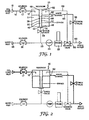
- Referring to
Figure 1 , apparatus is shown for measuring the concentration of a ClO2-dosed sample of sterilizing fluid. The apparatus includes areservoir 10 containing sterilizingfluid 11, and having areservoir inlet 12 and areservoir outlet 14. Thereservoir inlet 12 is connected to a ClO2-dosedsample supply line 16 having a ClO2 inlet 18 for connection to a source of ClO2-dosed sterilizingfluid 11. - A
first solenoid valve 17 for selectively allowing ClO2-dosed sterilizingfluid 11 into thereservoir 10 is disposed insample supply line 16 upstream of thereservoir inlet 12 - The
reservoir outlet 14 is connected to asample channel 20. Aprobe 22 for measuring the concentration of ClO2 in the sterilizingfluid 11 is located in thesample channel 20. Apump 24 is also located in thesample channel 20, and is used for pumping fluid through thesample channel 20. In this example, thepump 24 is a KNF pump which has a 6 Bar (0.6 MPa) pressure rating. - The
sample channel 20 has a sample -channel inlet 28 for connection to a source of water. Asecond solenoid valve 30 is provided in thesample channel 20, downstream of thesample channel inlet 28 for selectively allowing water to flow through thesample channel 20. The second solenoid valve could equally usefully be located upstream of thesample channel inlet 28 instead. - A
syphon 32 is connected between thereservoir 10 and thesample channel 20. Thesyphon 32 is located within thereservoir 10 between the fluid 11 and thereservoir outlet 14, such that the fluid in the reservoir must flow through thesyphon 32 to reach thereservoir outlet 14. - The
syphon 32 comprises aninner cylinder 36 and anouter cylinder 38. Thelower end 40 of theinner cylinder 36 surrounds thereservoir outlet 14, and hasside walls 42 which extend upwards towards the top of thereservoir 10. Theinner cylinder 36 has an opentop end 44. - The
outer cylinder 38 surrounds theinner cylinder 36. The outer cylinder is upturned and has a sealedtop end 46 which is located near the top of the reservoir. Theouter cylinder 38 has an openbottom end 48 which is located near thereservoir outlet 14. Theouter cylinder 38 hasside walls 50 extending from the top of thereservoir 10 towards the bottom of thereservoir 10. - There is a
gap 52 between thelower end 48 of theouter cylinder 38 and the bottom of thereservoir 10. Thegap 52 allows fluid in thereservoir 10 to enter thesyphon 32. The gap is shown more clearly inFigure 10 . - A
reservoir check valve 54 is located outside thereservoir 10 adjacent thereservoir outlet 14. Thereservoir check valve 54 is a one way valve and prevents fluid from entering the reservoir through thereservoir outlet 14. - The embodiment of the invention illustrated in
Figure 1 also includes areturn channel 56. One end of thereturn channel 56 is connected to thesample channel 20 downstream of thepump 24. The other end of thereturn channel 56 feeds into thereservoir 10. Thereturn channel 56 is used for carrying fluid from thesample channel 20 to thereservoir 10. - A
third solenoid valve 58 is located at the junction between thesample channel 20 and thereturn channel 56. Thethird solenoid valve 58 is used for directing fluid in the -sample channel 20 either through thereturn channel 56 and into thereservoir 10, or through awaste outlet pipe 60. - An
overflow outlet 62 is located in thereservoir 10 to prevent the tank from overflowing. Awaste channel 64 connects theoverflow outlet 62 to thewaste outlet pipe 60. Awaste check valve 66 is located in thewaste channel 64 for preventing fluid passing from thewaste channel 64 into thereservoir 10. - The following describes the principles of operation of the above described apparatus:
- Dosed sterilizing
fluid 11 from a dosed sterilizing fluid generator (not shown) enters thereservoir 10 through thereservoir inlet 12. Flow through thereservoir inlet 12 is controlled by thefirst solenoid valve 17. In this example, thereservoir 10 holds about 100 ml of dosed sterili-zing fluid 11. Surplus dosed sterilizingfluid 11 escapes out of thereservoir 10 through theoverflow outlet 62. Thewaste check valve 66 in thewaste outlet pipe 64 ensures that liquid can only pass out of, and not into, the reservoir through the waste outlet. - Undosed water enters the system through the
water inlet 28. Thewater inlet 28 is controlled by thesecond solenoid valve 30. This water is used to flush thereservoir 10, pump 24 andprobe 22 to remove traces of ClO2. - The
pump 24 andprobe 22 are connected to thereservoir outlet 14. Thereservoir check valve 54 ensures that liquid can only be pumped out of, and not into, thereservoir 10. Thereservoir outlet 14 is separated from the liquid in the reservoir by thesyphon 32. Unless liquid is being pumped out of thereservoir 10, thesyphon 32 is filled with air and forms an air lock that separates the contents of thereservoir 10 from thesample channel 20. - The
third solenoid valve 58 controls the flow of fluid from thepump 24. Fluid can either be pumped through thereturn channel 56 and up to thereservoir 10, or out to thewaste outlet pipe 60. - The sequence of operation for the apparatus will now be described with reference to
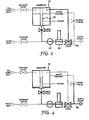
Figure 1 , and with additional reference toFigures 2-9 . InFigures 2-9 , heavy black lines are used to highlight the relevant parts of the apparatus used for each stage of operation. Reference numbers in the text refer to the parts as indicated inFigure 1 . - Referring to
Figure 2 , thefirst solenoid valve 17 is opened and dosed sterilizingfluid 11 is admitted into thereservoir 10. The fill rate depends upon the system flow rate and pressure, and this is generally controlled by the device receiving the dosed sterilizingfluid 11. The system is suitable for use in a range of devices for cleaning endoscopes or other medical equipment. These devices tend to operate at different pressures and flow rates depending on the device type and manufacturer. There is a fixed jet size on thereservoir inlet 12, therefore the volume of dosed sterilizingfluid 11 admitted into thereservoir 10 will typically be in the range of about 40 - 100 ml when the system is used with washers/disinfectant machines such as the Dawmed Clinic (RTM) and the Medivator (RTM). Typical line pressures for these devices are in the range 1.03-4.14 bar (15-60 psi), and typical flow rates are in the range 3-20 litres/minute. - The
overflow outlet 62 enables the system to adapt to such different supply pressures and flow rates. Excess of dosed sterilizingfluid 11 flows through theoverflow outlet 62 to waste. Preferably, however, thereservoir 10 is filled with at least about 40 ml of dosed sterilizingfluid 11, and wastage is minimised by ensuring that no more than about 100 ml enters thereservoir 10. Thefirst solenoid valve 17 is opened for a sufficient period of time to fill thereservoir 10 with at least 40 ml of dosed sterilizingfluid 11. The flow rate and pressure varies with application, so a minimum time can be set in which thefirst solenoid valve 17 remains open to ensure at least 40 ml enters thereservoir 10, or the time in which thefirst solenoid valve 17 remains open can be changed to suit the application. - Referring to
Figure 3 , thethird solenoid valve 58 is set to allow fluid to be pumped up to thereservoir 10. Thepump 24 is activated to perform the pumping. Air in thesyphon 32 is drawn through thepump 24 andprobe 22. When the air in thesyphon 32 has been evacuated, dosed sterilizingfluid 11 is drawn through thepump 24 andprobe 22 and is pumped back up to thereservoir 10 through thereturn channel 56. Dosed sterilizingfluid 11 is circulated for two minutes to allow theprobe 22 to measure the ClO2 concentration and provide a stable result. - The flow rate is determined by the recommended flow rate across the
probe 22 which is defined by the probe manufacturer, but is typically in the range 100 - 200 ml/minute. To achieve such a flow rate, a pump such as a KNF (RTM) diaphragm pump, may be used which operates at a flow rate of 100-150 ml/minute at 24 volts. - Referring to
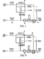
Figure 4 , thethird solenoid valve 58 is set to allow liquid to be pumped to waste. The contents of thereservoir 10 are pumped to waste. - Referring to
Figure 5 , thesecond solenoid valve 30 is opened to allow water into thesample channel 20. Thethird solenoid valve 58 is set to direct fluid to waste and prevent fluid from passing up to thereservoir 10. Thepump 24 is used to pump water through thesample channel 20 and through theprobe 22 to waste. - Referring to
Figure 6 , thethird solenoid valve 58 is set to allow water to be pumped up to thereservoir 10. Thereservoir 10 is filled with water and allowed to overflow through theoverflow outlet 62, through thewaste channel 64 andwaste check valve 66 to waste. - Referring to
Figure 7 , thesecond solenoid valve 30 is closed and thethird solenoid valve 58 is opened to direct water from thereservoir 10 to waste. Thepump 24 is activated to pump the contents of thereservoir 10 to waste for one minute, or for a time period long enough to ensure that thereservoir 10 is completely emptied. - Referring to
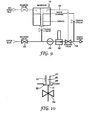
Figure 8 , thethird solenoid valve 58 is set to direct fluid to thereservoir 10. Thepump 24 is activated to pump a slug of water in thereturn channel 56 into thereservoir 10. Thethird solenoid valve 58 is then set to direct fluid to waste, and thepump 24 is activated to pump the slug of water out of thereservoir 10 to waste. At this stage, all of the system tubes are empty. - Referring to
Figure 9 , thesecond solenoid valve 28 is opened and water is flushed through thepump 24 and theprobe 22 to waste. Thepump 24 is stopped, and thesecond solenoid valve 28 is closed. Thethird solenoid valve 58 is set to direct water to thereservoir 10. Since the pump is not activated at this stage, and thesecond solenoid valve 28 is close, water does not pass into thereservoir 10 through thereturn channel 56. Instead, the water is trapped in thesample channel 20, which leaves theprobe 22 immersed in water. Thereservoir 10 is now empty and ready for the next refill and sample cycle to begin. - We have found that, with the chemical compositions used, agitation increases the measured ClO2 concentration in a sample. When a sample is first mixed the measured ClO2 concentration falls quite rapidly if the sample is not agitated. The measured concentration rises if the sample is agitated. If we agitate a mixed sample by hand, and each time take a measurement, we find that the measurement varies. If we agitate the sample using the pump, the agitation is much more consistent, as the speed of the motor and the time the motor is operated for are software controlled, and the measured Cl02 concentration is much more consistent.
- Thus, the consistency of the measured result is influenced by the agitation of the fluid through the pump. The exemplified system uses a consistent agitation and produces very consistent results.
- A chlorine dioxide generator incorporating the apparatus of
Figure 1 is illustrated schematically in the flow sheet ofFigure 11 . The generator is suitable for producing a stream of aqueous chlorine dioxide (ClO2) sterilizing fluid for use in sterilizing medical and dental instruments or for wound irrigation or skin asepsis. The -concentration of ClO2 will be varied according the intended application. The method of generating ClO2 is similar to that described inWO2005/011759 A1 with respect toFigure 5 therein. - The apparatus comprises a first pump connected to a source of base and a second pump connected to a source of activator. The therms 'base' and 'activator' are used herein to refer to fluids which when mixed react to produce aqueous ClO2. The reaction mixture preferably has a pH in the range 4.5 to 6.5, notably 5.5 to 6.5. In this example, the base and activator are comprised as set forth in Example 3 of
US 5,696,046 . - The output from each pump connects to the proximal end of a tubular helical coil (ClO2 mixing coil) which functions as an elongate reaction chamber. As pumping continues, reaction mixture is pumped progressively through the mixing coil to the distal end of the coil. With pumping continuing, the reaction mixture passes from through the mixing coil in about 30 seconds, during which time the reaction to form ClO2 is substantially complete. With further pumping, the reaction mixture is injected into a conduit through which passes a stream of water. The reaction mixture mixes with the water to form a stream of aqueous ClO2 sterilizing fluid. Depending on the rate of pumping, the concentration of ClO2 in the sterilizing fluid can, in this example, be varied between about 20 ppm and about 200 ppm. Concentrations above or below this range may be generated either by varying the pumping rate, the water flow rate, or the concentration of reagents.
- In this example each pump is a diaphragm pump, although other types of pump, notably piston pumps, could be used. The diaphragm pumps use an elastomeric diaphragm to draw fluid in and to expel fluid from the pumping chamber. On the downstroke the diaphragm draws fluid into the chamber through an inlet valve and on the up-stroke the diaphragm forces fluid out through an outlet valve. The pumps are self-priming. They can provide pumping pressures up to 600 kPa and flow rates in the range 0 to 300 ml/min. Advanced motor control technology speeds up the motor on the intake stroke to minimize fluid output pulsing. In this example, the pump body and valve components are made from stainless steel, and the diaphragms are coated with PTFE. A variety of motor and encoder options are available to drive and control operation of the pumps. In the present example, the pumps are operated under stepper motor control and monitored by means of optical encoders mounted on the motor shafts. The optical encoders measure graticules as they pass the optical sensor, giving precise measurement of shaft rotation, and hence volume pumped. The displacement volume for each pump per cycle is about 0.5 ml.
- Each pump is provided with a pressure regulator (pressure control valve), which ensures that pumping is carried out against a substantially constant back pressure. The pressure control valve comprises a spring-biased piston against which the pump works. This arrangement ensures that the pump operates at a constant pressure regardless of the pressure in the water supply. To increase the working life of the pressure control valves it is preferred that the valve fittings are coated with PTFE or a fluoroelastomeric material which has good resistance to chemical attack. In the present example example, the back pressure is 4 bar (400 kPa), which is the same as the nominal mains water pressure in the conduit. All pumps are affected by back-pressure, which reduces the flow rate. By setting a constant back pressure, the pressure experienced by the pumps is kept constant, which in turn keeps the volume expelled during each pump cycle substantially constant. Thus, the apparatus enables precisely controlled quantities of reagents to be mixed and injected into the water stream, thereby providing a stream of sterilizing fluid with the concentration of ClO2 controlled to within the limits demanded by particular applications within a medical or surgical facility. In a preferred embodiment, the spring pressure may be adjusted if desired, to permit corresponding adjustment to the bolus volume delivered by the pump.
- PTFE tube connections are used to connect the pump outputs to the mixing coil, with stainless steel fittings used to provide greater resistance to damage from ClO2. The valves are stainless steel solenoid valves with Viton® fluoroelastomer fittings. Suitable valves are sold by Parker Hannifin and Cole Palmer.
- The mixing coil in this example is a vertically-mounted stainless steel helical tube. The volume capacity of the coil is selected according to the intended application. For most applications, the mixing coil will have a 20 ml capacity. However, for alternative product variants, the coil may have a greater capacity, for example 100 ml capacity, based on a preferred mixing time of 30 seconds. The tubing which carries the activator and base solutions to their respective pumps is provided with a 100 µm filter and a check valve to ensure one-way travel of fluid. The ClO2 solution is injected into the mains water supply via a solenoid valve. If air is initially in the system this may be bled off via a bleed valve.
- In this embodiment, the dosed water outlet line has a check valve, which ensures that water will not pass through until a preset pressure of 100 kPa is reached. This arrangement ensures that the system is always pressurized when in use.
- The system includes an arrangement for priming and purging the system. Priming the system involves initially filling the diaphragm pumps with water so that they can operate on liquids, which they pump efficiently, and not air, which can cause diaphragm pumps problems. Purging the system involves flushing aqueous ClO2 out with water to prevent long-term contact of the internal surfaces with ClO2, which is desirable to increase the operating lifetime of the system. To initiate purging, the solenoid purge valve is opened, permitting water to pass through a purge line to the tubing which connects the base and activator sources to the diaphragm pumps. The purge water passes through a 100 µm filter, and check valves ensure that the purge water passes up through the pumps and into the mixing coil. With the ClO2 injection solenoid valve closed, and a purge outlet solenoid valve open, purge water passes from the coil and leaves through a waste outlet. To prime the pumps without purging the coil, the solenoid prime valves are opened so that water which passes through the pumps goes directly to the waste outlet. A 100 kPa check valve connects the output from the purge inlet to waste, thereby limiting purge water pressure. Similarly, a 500 kPa check valve is provided to vent redaction products from the mixing coil to waste to prevent dangerous excess of pressure if the ClO2 injection valve and the purge outlet valves are closed. A drain valve is provided to permit manual draining of the coil to waste.
- The washer needs 40 ml of ClO2 solution from the mixing coil to dose the rinse water of the 15 litre sink at the rate of 40 ml/minute. Base and Activator are injected into the base of the mixing coil by the two pumps. The internal volume of the coil is 20 ml. It takes 30 seconds for the Base and Activator to fill the coil. During the 30 seconds the Base and Activator are thoroughly mixed and ClO2 is produced. The Base and Activator pump -continue to push the 20 ml packet of ClO2 out of the mixing coil and into the water line at 400 kPa at the demand rate of 40 ml/minute. At the end of the delivery cycle the mixing coil is still full of ClO2. Software control may be used to determine whether to hold this ClO2 in the coil, because there is an expectation that another batch will be required in a pre-determined period, or whether to flush it out using Base or water.
- The washer needs 160 ml of ClO2 solution to dose both chambers of a washer disinfection machine at the rate of 40 ml/minute. We proceed exactly as Example 1 above but continue to mix and pump ClO2 at the rate of 40 ml/minute until 160 ml of ClO2 has been dispensed into the water supply. At the end of the delivery cycle the mixing coil can be flushed with Base or water or the ClO2 retained as required.
- The flow control apparatus of
Figure 1 inputs ClO2 dosed water from the water supply line downstream of the point where the reaction mixture from the mixing coil is injected into the water stream. The fresh water feed to the probe system in this example is taken from the upstream side of the water inlet flow meter. To ensure that the fresh water feed to the probe can be closed for servicing, solenoid valve V2 is provided at the base of the reservoir. This arrangement has the benefit that when fresh water is drawn into the probe manifold system to flush the reservoir, the flow meter does not detect it and the Generator is not activated. - In an alternative preferred configuration the fresh water feed to the probe would be located between the flow restrictor outlet and the flow meter inlet so that when the regulator is closed the water supply to both the Generator and the probe may be isolated from the mains.
- As described above with reference to
Figures 1-10 , the syphon system permits the probe to measure the concentration of ClO2 in the dosed water, and then to flush the probe with fresh water which is subsequently pumped to a waste outlet. - This aspect of the invention provides a chlorine dioxide generator with means for accurately measuring ClO2 concentration when desired.
- Timings for flushing of the probe may be implemented in software. The timings may be varied for different applications and component sizes; examples of timings are given below.
- Duration of ProbeFlush() FLUSH1 state, in which the sample tank is emptied: FLUSH1_TIME=75 secs
- Duration of ProbeFlush() FLUSH2 state, in which pump and probe is flushed with clean water: FLUSH2_TIVE=5 secs
- Duration of ProbeFlush() FLUSH3 state, in which the sample tank is filled with clean water: FLUSH3_TIME=30 secs
- Duration of ProbeFlush() FLUSH4 state, in which the sample tank is emptied of clean water: FLUSH4_TIME=75 secs
- Duration of ProbeFlush() FLUSH4A state, in which the slug of fluid in the recirculation tubing is transferred to the sample tank: FLUSH4A_TIME=5 secs
- Duration of ProbeFlush() FLUSH4B state, in which the slug of fluid in the sample tank is emptied to waste: FLUSH4B_TIME=5 secs
- Duration of ProbeFlush() FLUSH5 state, in which pump and probe is flushed with clean water: FLUSH5_TIME=2 secs
- Duration of recirculation time, in which dosed water is passed across the probe. This duration is determined by the response time of the probe: RECIRCULATE_TIME=120 secs
- It should be understood that the invention has been described by way of example only and that modifications in detail may be made without departing from the scope of the invention as specified in the claims.
Claims (26)
- Apparatus for controlling the flow of fluids through a sample channel (20), the apparatus comprising:a reservoir (10) having a reservoir inlet (12), the reservoir inlet (12) being for connection to a source of a first fluid;a sample channel (20) having a sample channel inlet (28), the sample channel inlet (28) being for connection to a source of a second fluid; characterised by:a syphon (32) connected between the reservoir (10) and the sample channel (20);means (30,58) for trapping fluid in at least part of the sample channel (20);
wherein the apparatus is configured such that in use air can be allowed into the syphon (32) to create an air gap in the syphon, the air gap preventing first fluid in the reservoir (10) from contacting trapped fluid in the sample channel (20);the apparatus further comprising pump means (24) for pumping fluid out of the sample channel (20) and for pumping air out of the syphon (32) such that fluid in the reservoir (10) can flow through the syphon (32) and into the sample channel (20). - Apparatus as claimed in Claim 1, wherein the syphon (32) comprises an inner portion (36) and an outer portion (38), the outer portion having a closed end (46) located near the top of the reservoir, and an open end (48) located near the bottom of the reservoir, the inner portion (36) being located within the outer portion (38) and surrounding the reservoir outlet (14), the inner portion having sidewalls (42) extending from the bottom of the reservoir towards the top of the reservoir.
- Apparatus as claimed in Claim 2, wherein the inner (36) and outer (38) portions are concentric cylinders.
- Apparatus as claimed in Claim 2 or Claim 3, wherein the reservoir (10) further comprises fluid level control means (62) for controlling the level of fluid in the reservoir such that the fluid level does not exceed a maximum fill level.
- Apparatus as claimed in Claim 4, wherein the fluid level control (62) means comprises an overflow outlet.
- Apparatus as claimed in Claim 4 or Claim 5, wherein the height of the sidewalls (42) of the syphon inner portion (36) are substantially equal to or greater than the maximum fill level.
- Apparatus as claimed in any preceding claim, further comprising a probe (22) located within the sample channel (20) for analysing a property of a fluid from the reservoir.
- Apparatus as claimed in Claim 7, wherein the probe (22) is a probe for measuring the concentration of chlorine dioxide in an aqueous fluid.
- Apparatus as claimed in Claim 7 or Claim 8, further comprising a return channel (56) connected between the sample channel (20) and the reservoir (10), the return channel (56) being connected to the sample channel (20) downstream of the probe (22).
- Apparatus as claimed in Claim 9, wherein a solenoid valve (58) is located between the sample channel (20) and the return channel (56) to selectively direct fluid from the sample channel (20) through the return channel (56) or towards a waste outlet (60).
- Apparatus as claimed in any preceding claim, wherein the pump means includes a pump (24) located in the sample channel (20).
- Apparatus as claimed in any preceding claim, wherein the pump means is a single pump (24).
- Apparatus as claimed in Claim 12, wherein the single pump (20) may be used for pumping the first and second fluids through the sample channel (20), through the return channel (56), and through the reservoir (10).
- Apparatus as claimed in any preceding claim, wherein a check valve (54) is located between the sample channel (20) and the reservoir (10) to prevent fluid from passing from the sample channel into the reservoir.
- Apparatus as claimed in any preceding claim, wherein a solenoid valve (17) is located between the source of the first fluid (18) and the reservoir (10) for selectively allowing fluid to enter the reservoir.
- Apparatus as claimed in any preceding claim, further including a solenoid valve (30) for selectively allowing the second fluid to flow through the sample channel (20).
- Apparatus as claimed in any preceding claim, wherein the means for trapping fluid in at least part of the sample channel comprises two solenoid valves (30,58) located at either end of said part of the sample channel (20).
- Apparatus as claimed in any preceding claim, wherein the reservoir (10) is a sealed unit.
- Apparatus as claimed in Claim 18, wherein the reservoir (10) has a duckbilled valve.
- A method of controlling the flow of fluids through a sample channel (20), the method comprising the steps of:providing a reservoir (10);providing a sample channel (20); characterised by:providing a syphon (32) connecting the reservoir (10) and the sample channel (20);trapping a second fluid in at least a part of the sample channel (20);allowing the syphon (32) to fill with air;filling the reservoir (10) with a first fluid;the air in the syphon preventing the first fluid in the reservoir from entering the sample channel (20) and contacting the trapped second fluid;providing pump means (24);pumping second fluid out of the sample channel (20);pumping air out of the syphon (32) and pumping at least some of the first fluid out of the reservoir (10) and through the syphon (32) into the sample channel (20).
- A method according to claim 20, further comprising measuring the concentration of a component of a fluid in the sample channel (20) by:providing a probe (22) located in the sample channel (20);submersing at least part of the probe (22) in the second fluid when the second fluid is trapped in the sample channel;andusing the probe to measure the concentration of a component of the first fluid when the first fluid has been pumped through the syphon (32) into the sample channel (20).
- A method as claimed in Claim 21, further comprising the steps of:providing a return channel (56) connected between the sample channel (20) and the reservoir (10), the return channel (56) being connected to the sample channel (20) downstream of the probe (22);directing the first fluid along the return channel (56) and back into the reservoir (10);pumping the recirculated first fluid from the reservoir (10) and through the sample channel (20) and past the concentration probe (22);continuing the above steps for a predetermined time period;pumping the contents of the reservoir (10) to waste after the predetermined time period.
- A method as claimed in Claim 22, wherein the predetermined sample time period is approximately 2 minutes.
- A method as claimed in Claim 22 or Claim 23, further comprising the steps of:providing a valve (30) to selectively allow second fluid to flow through the sample channel (20); andproviding a valve (58) to selectively direct fluid from the sample channel (20) to the return channel (56);wherein the step of trapping second fluid in the sample channel (20) is achieved by setting the valves so that water is prevented from entering the sample channel (20), and so that fluid in the sample channel (20) is directed to the return channel (56).
- A method as claimed in any one of Claims 21 to 24, further comprising the step of providing verifying means to automatically check whether the measured concentration value is within a predetermined tolerance of a desired concentration value.
- A method as claimed in Claim 25, further comprising the step of providing display means for displaying a pass or fail notice to indicate whether the concentration is within the predetermined tolerance or not.
Applications Claiming Priority (2)
| Application Number | Priority Date | Filing Date | Title |
|---|---|---|---|
| GB0508657A GB0508657D0 (en) | 2005-04-29 | 2005-04-29 | Flow control |
| PCT/GB2006/001542 WO2006117518A1 (en) | 2005-04-29 | 2006-04-26 | Flow control |
Publications (2)
| Publication Number | Publication Date |
|---|---|
| EP1875321A1 EP1875321A1 (en) | 2008-01-09 |
| EP1875321B1 true EP1875321B1 (en) | 2010-01-13 |
Family
ID=34674013
Family Applications (1)
| Application Number | Title | Priority Date | Filing Date |
|---|---|---|---|
| EP20060726924 Not-in-force EP1875321B1 (en) | 2005-04-29 | 2006-04-26 | Flow control |
Country Status (7)
| Country | Link |
|---|---|
| US (1) | US20080314450A1 (en) |
| EP (1) | EP1875321B1 (en) |
| AT (1) | ATE455322T1 (en) |
| DE (1) | DE602006011730D1 (en) |
| ES (1) | ES2338454T3 (en) |
| GB (1) | GB0508657D0 (en) |
| WO (1) | WO2006117518A1 (en) |
Cited By (1)
| Publication number | Priority date | Publication date | Assignee | Title |
|---|---|---|---|---|
| KR20150101142A (en) * | 2014-02-26 | 2015-09-03 | 주식회사 미성에스앤아이 | a residual chlorine detector and the multi-funtional residual chlorine detecting system using thereof |
Families Citing this family (12)
| Publication number | Priority date | Publication date | Assignee | Title |
|---|---|---|---|---|
| KR101602414B1 (en) * | 2009-03-16 | 2016-03-11 | 삼성전자주식회사 | Apparatus for fluidic control |
| WO2010129841A1 (en) * | 2009-05-07 | 2010-11-11 | Smith Clyde M | Fluid dispensing system with thermal control |
| KR20110046935A (en) * | 2009-10-29 | 2011-05-06 | 포항공과대학교 산학협력단 | Droplet discharging device |
| ES2936062T3 (en) | 2011-05-06 | 2023-03-14 | Emd Millipore Corp | Automatic aseptic sampling valve for sampling from closed containers |
| WO2013063128A1 (en) | 2011-10-24 | 2013-05-02 | Bend Research, Inc. | Systems and methods for producing bioproducts |
| WO2013152361A1 (en) * | 2012-04-06 | 2013-10-10 | Corsolutions Llc | Apparatus, system, & method providing fluid flow for cell growth |
| US9389151B2 (en) * | 2012-11-05 | 2016-07-12 | Bend Research, Inc. | Fixed volume aseptic sampling valve for sampling from enclosed containers |
| ES2747355T3 (en) * | 2012-12-07 | 2020-03-10 | Ecolab Usa Inc | System for handling the movement of liquid products |
| US10967084B2 (en) * | 2017-12-15 | 2021-04-06 | Asp Global Manufacturing Gmbh | Flow restrictor |
| IT201900005314A1 (en) * | 2019-04-08 | 2020-10-08 | Tema Sinergie S P A | VAPORIZER OF DECONTAMINATING AGENTS |
| DE102019120415A1 (en) * | 2019-07-29 | 2021-02-04 | Endress+Hauser Conducta Gmbh+Co. Kg | Method for determining a chemical absorption capacity of a process medium in a measuring point and also measuring point for determining a chemical absorption capacity of a process medium |
| DE102019120420A1 (en) * | 2019-07-29 | 2021-02-04 | Endress+Hauser Conducta Gmbh+Co. Kg | Method for calibrating an analytical measuring device and measuring point for analyzing a process medium and for calibrating an analytical measuring device |
Family Cites Families (24)
| Publication number | Priority date | Publication date | Assignee | Title |
|---|---|---|---|---|
| US630988A (en) * | 1899-04-14 | 1899-08-15 | Hans Reisert | Filter. |
| FR1541696A (en) * | 1967-06-01 | 1968-10-11 | Commissariat Energie Atomique | Air operated liquid dispenser |
| US3672508A (en) * | 1970-01-20 | 1972-06-27 | James O Simon | Swimming pool chlorinator apparatus |
| US3949615A (en) * | 1974-05-13 | 1976-04-13 | Instrumentation Laboratory, Inc. | Analysis apparatus |
| US4176032A (en) * | 1978-03-03 | 1979-11-27 | Fischer & Porter Co. | Chlorine dioxide analyzer |
| US4216185A (en) * | 1978-10-16 | 1980-08-05 | Hopkins Dale W | Method and apparatus for purging disinfecting high purity water distribution systems |
| US4250144A (en) * | 1979-06-14 | 1981-02-10 | Fischer & Porter Company | Chlorine dioxide generating system |
| DE3400263A1 (en) * | 1984-01-05 | 1985-07-18 | Göldner - Vieregge-Bruns Hygienetechnik GmbH, 3070 Nienburg | Device for monitoring the concentration at which disinfectant solutions are used |
| GB2175399B (en) * | 1985-05-20 | 1989-10-11 | Us Energy | Selective chemical detection by energy modulation of sensors |
| US4886653A (en) * | 1988-03-25 | 1989-12-12 | Olin Corporation | Process and apparatus for producing an aqueous solution containing chlorine dioxide and chlorine |
| US5273583A (en) * | 1990-07-02 | 1993-12-28 | Xerox Corporation | Fabrication of electrophotographic imaging members |
| US5269832A (en) * | 1992-06-03 | 1993-12-14 | Winfield Industries | Method and apparatus for continuously measuring the concentration of chemicals in solutions |
| GB9420201D0 (en) * | 1994-10-06 | 1994-11-23 | Green Bruce P | Cold sterilant solution |
| US5649647A (en) * | 1995-08-10 | 1997-07-22 | Kodarar; Joseph | Transfer pump for chlorinated liquid |
| US6051135A (en) * | 1996-02-23 | 2000-04-18 | Water Technologies Limited | Apparatus for making aqueous chlorine dioxide and apparatus for treating water with aqueous chlorine dioxide |
| US5832948A (en) * | 1996-12-20 | 1998-11-10 | Chemand Corp. | Liquid transfer system |
| US6042802A (en) * | 1997-10-15 | 2000-03-28 | Medivators Inc. | Method and apparatus for generating and using chlorine dioxide |
| US5970999A (en) * | 1998-11-23 | 1999-10-26 | Maurice J. Greenia | Hydraulic vacuum pump |
| US6576059B2 (en) * | 1999-11-22 | 2003-06-10 | Harris & Bruno Company, Inc. | Chambered doctor blade system for water-based and UV-based coatings |
| SE0000344D0 (en) * | 2000-02-02 | 2000-02-02 | Sudhir Chowdhury | Disinfection of water |
| US20040101438A1 (en) * | 2002-09-10 | 2004-05-27 | Nelson Philip E. | Method and apparatus for sterilizing food containers |
| EP1620347A4 (en) * | 2003-02-24 | 2007-08-29 | Millipore Corp | Fluid dispensing apparatus having means for measuring fluid volume continuously |
| US6949196B2 (en) * | 2003-07-28 | 2005-09-27 | Fkos, Llc | Methods and systems for improved dosing of a chemical treatment, such as chlorine dioxide, into a fluid stream, such as a wastewater stream |
| US20070193932A1 (en) * | 2005-07-18 | 2007-08-23 | William Nightingale | Water purification system and method |
-
2005
- 2005-04-29 GB GB0508657A patent/GB0508657D0/en not_active Ceased
-
2006
- 2006-04-26 US US11/919,182 patent/US20080314450A1/en not_active Abandoned
- 2006-04-26 ES ES06726924T patent/ES2338454T3/en active Active
- 2006-04-26 EP EP20060726924 patent/EP1875321B1/en not_active Not-in-force
- 2006-04-26 WO PCT/GB2006/001542 patent/WO2006117518A1/en not_active Application Discontinuation
- 2006-04-26 DE DE200660011730 patent/DE602006011730D1/en active Active
- 2006-04-26 AT AT06726924T patent/ATE455322T1/en not_active IP Right Cessation
Cited By (1)
| Publication number | Priority date | Publication date | Assignee | Title |
|---|---|---|---|---|
| KR20150101142A (en) * | 2014-02-26 | 2015-09-03 | 주식회사 미성에스앤아이 | a residual chlorine detector and the multi-funtional residual chlorine detecting system using thereof |
Also Published As
| Publication number | Publication date |
|---|---|
| US20080314450A1 (en) | 2008-12-25 |
| ES2338454T3 (en) | 2010-05-07 |
| DE602006011730D1 (en) | 2010-03-04 |
| ATE455322T1 (en) | 2010-01-15 |
| GB0508657D0 (en) | 2005-06-08 |
| EP1875321A1 (en) | 2008-01-09 |
| WO2006117518A1 (en) | 2006-11-09 |
Similar Documents
| Publication | Publication Date | Title |
|---|---|---|
| EP1875321B1 (en) | Flow control | |
| RU2676689C2 (en) | Instrument reprocessor and methods of tool reprocessing | |
| JP6049685B2 (en) | Peritoneal dialysis disposable unit, controller, peritoneal dialysis system | |
| US20060051285A1 (en) | Chlorine dioxide generation | |
| CN201139787Y (en) | Cleaning and sterilizing device for endoscope | |
| CN101795618B (en) | Automated endoscope reprocessor | |
| FR2601258A3 (en) | MIXING APPARATUS FOR USE WITH CONCENTRATED LIQUIDS | |
| CN102369054A (en) | Fluid mixing device, medical fluid testing device, and endoscope processing device | |
| EP1644051B1 (en) | Chlorine dioxide generation | |
| JP2017506895A5 (en) | ||
| JP6667845B2 (en) | Method for producing hypochlorous acid water and generator | |
| EP3753525B1 (en) | Multi-port cap for reagent container | |
| US6230934B1 (en) | Method for measuring and delivering hyper-concentrated liquids | |
| JP4129721B2 (en) | Dialysate preparation device | |
| CN112305036B (en) | Method for determining a measurement point of the chemical intake capacity of a process medium and measurement point | |
| RU2396213C1 (en) | Installation for preparation and dosing of reagent solutions | |
| US20240058496A1 (en) | Chemical injection and metering module for sterilization system | |
| JP2007315252A (en) | Pump device | |
| WO2022243473A1 (en) | An apparatus, a system and a method for manufacturing disinfecting and cleaning compositions | |
| JP2010058050A (en) | Dental sterilized water producing system |
Legal Events
| Date | Code | Title | Description |
|---|---|---|---|
| PUAI | Public reference made under article 153(3) epc to a published international application that has entered the european phase |
Free format text: ORIGINAL CODE: 0009012 |
|
| 17P | Request for examination filed |
Effective date: 20070921 |
|
| AK | Designated contracting states |
Kind code of ref document: A1 Designated state(s): AT BE BG CH CY CZ DE DK EE ES FI FR GB GR HU IE IS IT LI LT LU LV MC NL PL PT RO SE SI SK TR |
|
| 17Q | First examination report despatched |
Effective date: 20080326 |
|
| DAX | Request for extension of the european patent (deleted) | ||
| GRAP | Despatch of communication of intention to grant a patent |
Free format text: ORIGINAL CODE: EPIDOSNIGR1 |
|
| GRAS | Grant fee paid |
Free format text: ORIGINAL CODE: EPIDOSNIGR3 |
|
| GRAA | (expected) grant |
Free format text: ORIGINAL CODE: 0009210 |
|
| AK | Designated contracting states |
Kind code of ref document: B1 Designated state(s): AT BE BG CH CY CZ DE DK EE ES FI FR GB GR HU IE IS IT LI LT LU LV MC NL PL PT RO SE SI SK TR |
|
| REG | Reference to a national code |
Ref country code: GB Ref legal event code: FG4D |
|
| REG | Reference to a national code |
Ref country code: CH Ref legal event code: EP |
|
| REG | Reference to a national code |
Ref country code: IE Ref legal event code: FG4D |
|
| REF | Corresponds to: |
Ref document number: 602006011730 Country of ref document: DE Date of ref document: 20100304 Kind code of ref document: P |
|
| REG | Reference to a national code |
Ref country code: NL Ref legal event code: VDEP Effective date: 20100113 |
|
| REG | Reference to a national code |
Ref country code: ES Ref legal event code: FG2A Ref document number: 2338454 Country of ref document: ES Kind code of ref document: T3 |
|
| LTIE | Lt: invalidation of european patent or patent extension |
Effective date: 20100113 |
|
| PG25 | Lapsed in a contracting state [announced via postgrant information from national office to epo] |
Ref country code: AT Free format text: LAPSE BECAUSE OF FAILURE TO SUBMIT A TRANSLATION OF THE DESCRIPTION OR TO PAY THE FEE WITHIN THE PRESCRIBED TIME-LIMIT Effective date: 20100113 |
|
| PG25 | Lapsed in a contracting state [announced via postgrant information from national office to epo] |
Ref country code: LT Free format text: LAPSE BECAUSE OF FAILURE TO SUBMIT A TRANSLATION OF THE DESCRIPTION OR TO PAY THE FEE WITHIN THE PRESCRIBED TIME-LIMIT Effective date: 20100113 Ref country code: IS Free format text: LAPSE BECAUSE OF FAILURE TO SUBMIT A TRANSLATION OF THE DESCRIPTION OR TO PAY THE FEE WITHIN THE PRESCRIBED TIME-LIMIT Effective date: 20100513 Ref country code: NL Free format text: LAPSE BECAUSE OF FAILURE TO SUBMIT A TRANSLATION OF THE DESCRIPTION OR TO PAY THE FEE WITHIN THE PRESCRIBED TIME-LIMIT Effective date: 20100113 Ref country code: PT Free format text: LAPSE BECAUSE OF FAILURE TO SUBMIT A TRANSLATION OF THE DESCRIPTION OR TO PAY THE FEE WITHIN THE PRESCRIBED TIME-LIMIT Effective date: 20100513 |
|
| PG25 | Lapsed in a contracting state [announced via postgrant information from national office to epo] |
Ref country code: SI Free format text: LAPSE BECAUSE OF FAILURE TO SUBMIT A TRANSLATION OF THE DESCRIPTION OR TO PAY THE FEE WITHIN THE PRESCRIBED TIME-LIMIT Effective date: 20100113 Ref country code: FI Free format text: LAPSE BECAUSE OF FAILURE TO SUBMIT A TRANSLATION OF THE DESCRIPTION OR TO PAY THE FEE WITHIN THE PRESCRIBED TIME-LIMIT Effective date: 20100113 Ref country code: LV Free format text: LAPSE BECAUSE OF FAILURE TO SUBMIT A TRANSLATION OF THE DESCRIPTION OR TO PAY THE FEE WITHIN THE PRESCRIBED TIME-LIMIT Effective date: 20100113 Ref country code: PL Free format text: LAPSE BECAUSE OF FAILURE TO SUBMIT A TRANSLATION OF THE DESCRIPTION OR TO PAY THE FEE WITHIN THE PRESCRIBED TIME-LIMIT Effective date: 20100113 |
|
| PG25 | Lapsed in a contracting state [announced via postgrant information from national office to epo] |
Ref country code: CY Free format text: LAPSE BECAUSE OF FAILURE TO SUBMIT A TRANSLATION OF THE DESCRIPTION OR TO PAY THE FEE WITHIN THE PRESCRIBED TIME-LIMIT Effective date: 20100113 Ref country code: BE Free format text: LAPSE BECAUSE OF FAILURE TO SUBMIT A TRANSLATION OF THE DESCRIPTION OR TO PAY THE FEE WITHIN THE PRESCRIBED TIME-LIMIT Effective date: 20100113 Ref country code: SE Free format text: LAPSE BECAUSE OF FAILURE TO SUBMIT A TRANSLATION OF THE DESCRIPTION OR TO PAY THE FEE WITHIN THE PRESCRIBED TIME-LIMIT Effective date: 20100113 Ref country code: RO Free format text: LAPSE BECAUSE OF FAILURE TO SUBMIT A TRANSLATION OF THE DESCRIPTION OR TO PAY THE FEE WITHIN THE PRESCRIBED TIME-LIMIT Effective date: 20100113 Ref country code: GR Free format text: LAPSE BECAUSE OF FAILURE TO SUBMIT A TRANSLATION OF THE DESCRIPTION OR TO PAY THE FEE WITHIN THE PRESCRIBED TIME-LIMIT Effective date: 20100414 Ref country code: EE Free format text: LAPSE BECAUSE OF FAILURE TO SUBMIT A TRANSLATION OF THE DESCRIPTION OR TO PAY THE FEE WITHIN THE PRESCRIBED TIME-LIMIT Effective date: 20100113 |
|
| PLBE | No opposition filed within time limit |
Free format text: ORIGINAL CODE: 0009261 |
|
| STAA | Information on the status of an ep patent application or granted ep patent |
Free format text: STATUS: NO OPPOSITION FILED WITHIN TIME LIMIT |
|
| PG25 | Lapsed in a contracting state [announced via postgrant information from national office to epo] |
Ref country code: MC Free format text: LAPSE BECAUSE OF NON-PAYMENT OF DUE FEES Effective date: 20100430 Ref country code: SK Free format text: LAPSE BECAUSE OF FAILURE TO SUBMIT A TRANSLATION OF THE DESCRIPTION OR TO PAY THE FEE WITHIN THE PRESCRIBED TIME-LIMIT Effective date: 20100113 Ref country code: CZ Free format text: LAPSE BECAUSE OF FAILURE TO SUBMIT A TRANSLATION OF THE DESCRIPTION OR TO PAY THE FEE WITHIN THE PRESCRIBED TIME-LIMIT Effective date: 20100113 Ref country code: BG Free format text: LAPSE BECAUSE OF FAILURE TO SUBMIT A TRANSLATION OF THE DESCRIPTION OR TO PAY THE FEE WITHIN THE PRESCRIBED TIME-LIMIT Effective date: 20100413 |
|
| REG | Reference to a national code |
Ref country code: CH Ref legal event code: PL |
|
| 26N | No opposition filed |
Effective date: 20101014 |
|
| PG25 | Lapsed in a contracting state [announced via postgrant information from national office to epo] |
Ref country code: DK Free format text: LAPSE BECAUSE OF FAILURE TO SUBMIT A TRANSLATION OF THE DESCRIPTION OR TO PAY THE FEE WITHIN THE PRESCRIBED TIME-LIMIT Effective date: 20100113 Ref country code: IE Free format text: LAPSE BECAUSE OF NON-PAYMENT OF DUE FEES Effective date: 20100426 |
|
| PG25 | Lapsed in a contracting state [announced via postgrant information from national office to epo] |
Ref country code: CH Free format text: LAPSE BECAUSE OF NON-PAYMENT OF DUE FEES Effective date: 20100430 Ref country code: LI Free format text: LAPSE BECAUSE OF NON-PAYMENT OF DUE FEES Effective date: 20100430 |
|
| PGFP | Annual fee paid to national office [announced via postgrant information from national office to epo] |
Ref country code: ES Payment date: 20110406 Year of fee payment: 6 Ref country code: FR Payment date: 20110411 Year of fee payment: 6 Ref country code: DE Payment date: 20110324 Year of fee payment: 6 Ref country code: GB Payment date: 20110322 Year of fee payment: 6 |
|
| PGFP | Annual fee paid to national office [announced via postgrant information from national office to epo] |
Ref country code: IT Payment date: 20110420 Year of fee payment: 6 |
|
| PG25 | Lapsed in a contracting state [announced via postgrant information from national office to epo] |
Ref country code: HU Free format text: LAPSE BECAUSE OF FAILURE TO SUBMIT A TRANSLATION OF THE DESCRIPTION OR TO PAY THE FEE WITHIN THE PRESCRIBED TIME-LIMIT Effective date: 20100714 Ref country code: LU Free format text: LAPSE BECAUSE OF NON-PAYMENT OF DUE FEES Effective date: 20100426 |
|
| PG25 | Lapsed in a contracting state [announced via postgrant information from national office to epo] |
Ref country code: TR Free format text: LAPSE BECAUSE OF FAILURE TO SUBMIT A TRANSLATION OF THE DESCRIPTION OR TO PAY THE FEE WITHIN THE PRESCRIBED TIME-LIMIT Effective date: 20100113 |
|
| GBPC | Gb: european patent ceased through non-payment of renewal fee |
Effective date: 20120426 |
|
| REG | Reference to a national code |
Ref country code: FR Ref legal event code: ST Effective date: 20121228 |
|
| PG25 | Lapsed in a contracting state [announced via postgrant information from national office to epo] |
Ref country code: GB Free format text: LAPSE BECAUSE OF NON-PAYMENT OF DUE FEES Effective date: 20120426 |
|
| PG25 | Lapsed in a contracting state [announced via postgrant information from national office to epo] |
Ref country code: IT Free format text: LAPSE BECAUSE OF NON-PAYMENT OF DUE FEES Effective date: 20120426 Ref country code: FR Free format text: LAPSE BECAUSE OF NON-PAYMENT OF DUE FEES Effective date: 20120430 |
|
| REG | Reference to a national code |
Ref country code: DE Ref legal event code: R119 Ref document number: 602006011730 Country of ref document: DE Effective date: 20121101 |
|
| REG | Reference to a national code |
Ref country code: ES Ref legal event code: FD2A Effective date: 20140109 |
|
| PG25 | Lapsed in a contracting state [announced via postgrant information from national office to epo] |
Ref country code: ES Free format text: LAPSE BECAUSE OF NON-PAYMENT OF DUE FEES Effective date: 20120427 |
|
| PG25 | Lapsed in a contracting state [announced via postgrant information from national office to epo] |
Ref country code: DE Free format text: LAPSE BECAUSE OF NON-PAYMENT OF DUE FEES Effective date: 20121101 |