EP1875187B1 - Internal combustion engine knock determination device - Google Patents
Internal combustion engine knock determination device Download PDFInfo
- Publication number
- EP1875187B1 EP1875187B1 EP06745988.3A EP06745988A EP1875187B1 EP 1875187 B1 EP1875187 B1 EP 1875187B1 EP 06745988 A EP06745988 A EP 06745988A EP 1875187 B1 EP1875187 B1 EP 1875187B1
- Authority
- EP
- European Patent Office
- Prior art keywords
- waveform
- internal combustion
- combustion engine
- angle
- vibration
- Prior art date
- Legal status (The legal status is an assumption and is not a legal conclusion. Google has not performed a legal analysis and makes no representation as to the accuracy of the status listed.)
- Active
Links
- 238000002485 combustion reaction Methods 0.000 title claims description 155
- 230000008859 change Effects 0.000 claims description 7
- 238000000034 method Methods 0.000 description 17
- 238000001514 detection method Methods 0.000 description 13
- 238000002474 experimental method Methods 0.000 description 10
- 230000001419 dependent effect Effects 0.000 description 9
- 230000006870 function Effects 0.000 description 8
- 230000000630 rising effect Effects 0.000 description 7
- 230000007423 decrease Effects 0.000 description 5
- 238000012545 processing Methods 0.000 description 5
- 239000000446 fuel Substances 0.000 description 4
- 238000005259 measurement Methods 0.000 description 4
- 238000010586 diagram Methods 0.000 description 3
- 239000000203 mixture Substances 0.000 description 3
- 230000004044 response Effects 0.000 description 3
- XLYOFNOQVPJJNP-UHFFFAOYSA-N water Substances O XLYOFNOQVPJJNP-UHFFFAOYSA-N 0.000 description 3
- 238000004458 analytical method Methods 0.000 description 2
- 238000013459 approach Methods 0.000 description 2
- 230000010354 integration Effects 0.000 description 2
- 238000001228 spectrum Methods 0.000 description 2
- 230000003321 amplification Effects 0.000 description 1
- 239000003054 catalyst Substances 0.000 description 1
- 239000000498 cooling water Substances 0.000 description 1
- 238000011161 development Methods 0.000 description 1
- 230000018109 developmental process Effects 0.000 description 1
- 230000009977 dual effect Effects 0.000 description 1
- 230000001747 exhibiting effect Effects 0.000 description 1
- 238000001914 filtration Methods 0.000 description 1
- 230000004907 flux Effects 0.000 description 1
- 238000002347 injection Methods 0.000 description 1
- 239000007924 injection Substances 0.000 description 1
- 239000011159 matrix material Substances 0.000 description 1
- 230000007246 mechanism Effects 0.000 description 1
- 238000012986 modification Methods 0.000 description 1
- 230000004048 modification Effects 0.000 description 1
- 238000010606 normalization Methods 0.000 description 1
- 238000003199 nucleic acid amplification method Methods 0.000 description 1
- 230000000737 periodic effect Effects 0.000 description 1
- 230000010363 phase shift Effects 0.000 description 1
- 238000002360 preparation method Methods 0.000 description 1
- 230000009467 reduction Effects 0.000 description 1
- 230000002194 synthesizing effect Effects 0.000 description 1
- 230000007704 transition Effects 0.000 description 1
- 238000001845 vibrational spectrum Methods 0.000 description 1
Images

Classifications
-
- G—PHYSICS
- G01—MEASURING; TESTING
- G01L—MEASURING FORCE, STRESS, TORQUE, WORK, MECHANICAL POWER, MECHANICAL EFFICIENCY, OR FLUID PRESSURE
- G01L23/00—Devices or apparatus for measuring or indicating or recording rapid changes, such as oscillations, in the pressure of steam, gas, or liquid; Indicators for determining work or energy of steam, internal-combustion, or other fluid-pressure engines from the condition of the working fluid
- G01L23/22—Devices or apparatus for measuring or indicating or recording rapid changes, such as oscillations, in the pressure of steam, gas, or liquid; Indicators for determining work or energy of steam, internal-combustion, or other fluid-pressure engines from the condition of the working fluid for detecting or indicating knocks in internal-combustion engines; Units comprising pressure-sensitive members combined with ignitors for firing internal-combustion engines
- G01L23/221—Devices or apparatus for measuring or indicating or recording rapid changes, such as oscillations, in the pressure of steam, gas, or liquid; Indicators for determining work or energy of steam, internal-combustion, or other fluid-pressure engines from the condition of the working fluid for detecting or indicating knocks in internal-combustion engines; Units comprising pressure-sensitive members combined with ignitors for firing internal-combustion engines for detecting or indicating knocks in internal combustion engines
-
- G—PHYSICS
- G01—MEASURING; TESTING
- G01M—TESTING STATIC OR DYNAMIC BALANCE OF MACHINES OR STRUCTURES; TESTING OF STRUCTURES OR APPARATUS, NOT OTHERWISE PROVIDED FOR
- G01M15/00—Testing of engines
- G01M15/04—Testing internal-combustion engines
- G01M15/12—Testing internal-combustion engines by monitoring vibrations
Definitions
- the present invention relates to a knocking determination device and, more specifically, to a knocking determination device for an internal combustion engine that determines whether knocking occurs or not, based on vibration waveform of the internal combustion engine.
- Japanese Patent Laying-Open No. 2001-227400 discloses a knock control device for an internal combustion engine that can accurately determine whether the engine knocks.
- the knock control device for an internal combustion engine includes a signal detector detecting a signal representing a waveform of vibration occurring in the internal combustion engine (or a vibration waveform signal), an occurrence period detector detecting a period as an occurrence period during which the vibration waveform signal detected by the signal detector assumes a predetermined value or higher, a peak position detector detecting a peak position in the occurrence period detected by the occurrence period detector, a knock determiner determining whether the internal combustion engine knocks based on the relation between the occurrence period and the peak position, and a knock controller controlling an operation state of the internal combustion engine in accordance with a determination result of the knock determiner.
- the knock determiner determines knock (knocking) occurs when the peak position relative to the occurrence period is in a predetermined range.
- a signal representing a waveform of vibration occurring in the internal combustion engine is detected by a signal detector.
- An occurrence period during which the vibration waveform signal assumes a predetermined value or higher and a peak position therein are detected by an occurrence period detector and a peak position detector, respectively.
- the knock determiner can determine whether the engine knocks by detecting the position of the peak in the occurrence period of the vibration waveform signal. According to the knock determination result, the operation state of the internal combustion engine is controlled.
- the knock determiner When the peak position relative to the occurrence period is in a predetermined range, that is, when a waveform has such a shape that the peak position appears earlier relative to a predetermined length of the occurrence period of the vibration waveform signal, the knock determiner recognizes it as being particular to knocking. Thus, even in a transition state where an operation state of the internal combustion engine abruptly changes or when electric loads are turned on/off, whether or not the internal combustion engine knocks is accurately determined, and the operation state of the internal combustion engine can be controlled appropriately.
- a vibration that is greater in magnitude than a vibration attributed to knocking may sometimes be detected as noise. That is, in some cases a vibration attributed to a fault of a knock sensor or attributed to a vibration of the internal combustion engine itself may be greater in magnitude than a vibration attributed to knocking.
- the knock control device for an internal combustion engine of Japanese Patent Laying-Open No. 2001-227400 there has been a problem that the engine is erroneously determined as not knocking while the engine actually knocks, based on the fact that the peak position relative to the occurrence period is not within a predetermined range.
- Document EP-A-0 889 309 discloses a device for detecting and measuring knocking and an anti-knock control system using the same.
- the device for detection and measurement of pinking in an internal combustion engine has an acoustic emission sensor attached to the cylinder head, which supplies an electronic signal to an amplification and filtering circuit, which in turn is connected to a processing circuit for treatment of the signal from the sensor.
- the output from the processing circuit can be used with an anti-pinking mechanism that controls fuel injection to the engine.
- the processing electronics comprises a circuit, which applies a time window to the sensor, so that only data around top dead centre are considered, a rectifying circuit and an integrating circuit, of which the output amplitude is proportional to the degree of pinking.
- Document EP-A-0 454 486 discloses a method and apparatus of detecting knocking in an internal combustion engine having a crankshaft, which uses a knock detecting sensor to detect vibration caused by knocking.
- the signals from the knock detecting sensor are detected between a first and a second moment of time (i.e. a measurement window) and at least one of the first and second moments of time are independently varied in dependence upon a vibration spectrum of frequencies to be detected.
- a plurality of frequency spectra each having a different first and second moment of time, are each separately analysed for determining knock intensity.
- the moments of time are represented by first and second angles of the crankshaft.
- a plurality of measurement windows are used to determine the level of knocking and if the level exceeds a predetermined level the ignition timing for the engine is retarded.
- the frequency of maximum amplitude is arranged in operation to be the centre frequency of a frequency spectrum determined by the measurement window.
- Document US-A-5 537 855 discloses a knock detection method and an apparatus with dual integration windows.
- the knock detection method and apparatus integrates a knock sensor signal over a first period and provides a first integrated knock sensor signal, and integrates the knock sensor signal over a second period and provides a second integrated knock sensor signal.
- a knock indication is provided dependent on an amplitude of the first integrated knock sensor signal and an amplitude of the second integrated knock sensor signal and independent of the influence of the variations of the knock sensor potential sensor to sensor gain variation.
- Document US-A-5 343 843 discloses a knock control for high speed engine including a knock burst envelope follower.
- An ignition system for a vehicle engine has a fast response knock control which generates a rectified knock sensor signal having peaks at a knock frequency in accordance with the knock induced engine vibrations and samples and holds the voltage at each consecutive peak to generate a knock burst envelope signal in which knock burst envelopes correspond in amplitude and duration to knock vibration bursts in the knock sensor signal without phase shift induced group delay.
- the fast response is preserved in a fast response DC noise reference and an output which provides pulses at a frequency increasing with amplitude of the knock burst envelopes.
- Document DE 102 5 959 discloses a method for detecting knocking in petrol-driven external combustion engines, whereby the pressure in the combustion chamber is measured over the combustion cycle and the onset of knocking detected as high frequency variations superimposed on the cylinder pressure signal, and a device for detecting knocking in a petrol engine.
- the device comprises a cylinder head pressure sensor and a computer connected to the output signal for signal analysis purposes.
- Document EP-A-0 732 573 discloses a method and a device for recognizing vibration signals, e.g. knocking of internal combustion engines.
- the method involves selecting required data on engine parameters from a mapped table.
- the data is passed to a decoder in a separate memory.
- the decoded data is sent to a second memory.
- a reference signal is generated for use as one input to a multiplier.
- a vibration detector signal is used as the other input to the multiplier.
- the multiplied signal is then rectified.
- the rectified signal is integrated.
- the integrator is then set to zero with a signal from the decoder. A presence or absence of the signal is determined based upon a comparison of the integrated signal with a given threshold.
- Document EP-A-1 221 603 discloses a knock / misfire detection by wavelet transform.
- a system for detection of combustion anomalies in an internal combustion engine including a crank angle indicator, a vibration sensor, and a signal processor, wherein the signal processor receives signals from the indicator and the sensor, wherein a wavelet transform analysis of the signals from the sensor is performed to develop a vibration frequency signature on a time scale, the vibration frequency signature is compared to a predetermined value to determine the existence of anomalies in the combustion process, and the time scale of the vibration frequency signature is compared to the signal from the indicator to determine which of a plurality of cylinders of the internal combustion engine is exhibiting the combustion anomaly.
- Document DE 103 43 146 discloses a method of detecting cylinder pressure and/or faulty ignition and/or knock in an internal combustion engine with sensors involving processing signals of revolution rate sensors interacting with crankshaft and/or camshaft in a real-time controller.
- the method involves acquiring and processing the sensor signals of the revolution rate sensors interacting with the crankshaft and/or camshaft with a real-time controller, comparing current and previous signal pauses or periodic duration and relating the ratios or differences to values determined using a characteristic field or an algorithm.
- An object of the present invention is to provide a knock determination device that can determine whether the engine knocks with high accuracy.
- a knocking determination device for determining knocking of an internal combustion engine.
- the knocking determination device includes: a crank angle detecting unit detecting a crank angle of the internal combustion engine; a waveform detecting unit detecting a vibration waveform of the internal combustion engine between predetermined crank angles; a storage unit storing in advance one waveform representing vibration waveform corresponding t o knocking that does not change regardless of type and state of operation of the internal combustion engine; and a determining unit determining whether knocking occurred in the internal combustion engine or not, based on a result of comparison between the detected waveform and the waveform stored in the storage unit.
- the crank angle detecting unit detects the crank angle of the internal combustion engine
- the waveform detecting unit detects the waveform of vibration of the internal combustion engine between predetermined crank angles.
- the storage unit stores in advance one waveform of vibration corresponding to knocking, which does not change regardless of the type and state of operation of the internal combustion engine. Based on the result of comparison between the detected waveform and the stored waveform, whether the internal combustion engine knocks or not is determined.
- a knock waveform model as the vibration waveform that appears when knocking occurs may be formed and stored in advance, and by comparing the knock waveform model and the detected waveform, whether knocking occurred or not can be determined.
- the knock waveform model is one waveform that does not change dependent on the type and state of operation of the internal combustion engine. Therefore it becomes unnecessary to store a plurality of knock waveform models for different types and different states of operation of the internal combustion engine, and thus, the amount of data to be stored beforehand can be reduced.
- a knocking determination device that can accurately determine whether the knocking occurs or not in the internal combustion engine while enabling reduction in data amount to be stored beforehand can be provided.
- a knocking determination device for determining knocking of an internal combustion engine.
- the knocking determination device includes: a crank angle detecting unit detecting a crank angle of the internal combustion engine; a waveform detecting unit detecting a vibration waveform of the internal combustion engine between predetermined crank angles; a storage unit storing in advance a plurality of vibration waveforms of the internal combustion engine corresponding to states of operation of the internal combustion engine; and a determining unit determining whether knocking occurred in the internal combustion engine or not, based on a result of comparison between the detected waveform and a waveform corresponding to the state of operation of the internal combustion engine among the plurality of waveforms stored in the storage unit.
- the crank angle detecting unit detects the crank angle of the internal combustion engine
- the waveform detecting unit detects the waveform of vibration of the internal combustion engine between predetermined crank angles.
- the storage unit stores a plurality of vibration waveforms of the internal combustion engine that correspond to states of operation (such as the number of rotation of crank shaft) of the internal combustion engine. Based on the result of comparison between the detected waveform and the stored waveform, whether the internal combustion engine knocks or not is determined. Specifically, a plurality of knock waveform models representing vibration waveforms when knocking occurs, which correspond to the states of operations, are prepared through an experiment or the like and stored in advance.
- the knocking determination device further includes a rotation number sensing unit sensing the number of rotation of an output shaft of the internal combustion engine.
- the storage unit stores in advance a plurality of vibration waveforms corresponding to the number of rotation.
- the determining unit determines whether knocking occurred in the internal combustion engine or not, based on a result of comparison between the detected waveform and a waveform stored in the storage unit corresponding to the sensed number of rotation.
- the storage unit stores a plurality of vibration waveforms corresponding to the number of rotation of the output shaft of the internal combustion engine (crank shaft of the engine) obtained, by way of example, through an experiment. By comparing the detected waveform and the waveform that corresponds to the sensed number of rotation among the stored plurality of waveforms, it is possible to determine whether the knocking occurs or not in the internal combustion engine with high accuracy.
- the knocking determination device further includes a load factor sensing unit sensing a load factor of the internal combustion engine.
- the storage unit stores in advance a plurality of vibration waveforms corresponding to the load factor.
- the determining unit determines whether knocking occurred in the internal combustion engine or not, based on a result of comparison between the detected waveform and the waveform stored in the storage unit corresponding to the sensed load factor.
- the storage unit stores a plurality of vibration waveforms corresponding to the load factors of the internal combustion engine obtained, by way of example, through an experiment. By comparing the detected waveform and the waveform that corresponds to the sensed load factor among the stored plurality of waveforms, it is possible to determine whether the knocking occurs or not in the internal combustion engine with high accuracy.
- the knocking determination device further includes a rotation number sensing unit sensing the number of rotation of an output shaft of the internal combustion engine and a load factor sensing unit sensing a load factor of the internal combustion engine.
- the storage unit stores in advance a plurality of vibration waveforms corresponding to the number of rotation and the load factor.
- the determining unit determines whether knocking occurred in the internal combustion engine or not, based on a result of comparison between the detected waveform and the waveform stored in the storage unit corresponding to the sensed number of rotation and the sensed load factor.
- the storage unit stores a plurality of vibration waveforms corresponding to the number of rotation of the output shaft of the internal combustion engine (crank shaft of the engine) and to the load factors, obtained, by way of example, through an experiment. By comparing the detected waveform and the waveform that corresponds to the sensed number of rotation and load factor among the stored plurality of waveforms, it is possible to determine whether the knocking occurs or not in the internal combustion engine with high accuracy.
- the waveform stored in the storage unit is a waveform of a section between a first angle and a second angle.
- the first and second angles are both larger than, or both smaller than an angle that corresponds to a peak value of vibration waveform.
- either the rising portion or attenuating portion of the vibration waveform can be used as the knock waveform model. Therefore, by comparing the knock waveform model with the waveform of either the rising portion or attenuating portion of the detected waveform, the shape of waveform particular to knocking can be determined with high accuracy. Further, only the characteristic portion of vibration corresponding to knocking is stored, and therefore, the mount of data to be stored beforehand can b e reduced.
- the waveform stored in the storage unit is a waveform of a section between a first angle and a second angle.
- the section includes an angle that corresponds to a peak value of vibration waveform.
- the storage unit stores the waveform of a section between the first angle that corresponds to the peak value of vibration waveform and the second angle, and therefore, a waveform covering at least one of the rising portion and attenuating portion of the vibration waveform including the peak value can be used as the knock waveform model. Therefore, by comparing the knock waveform model with the waveform of the corresponding section, the shape of waveform particular to knocking can be determined with high accuracy, as the waveform of the portion including the peak value has high signal output. Further, only the characteristic portion of vibration corresponding to knocking is stored, and therefore, the amount of data to be stored beforehand can be reduced.
- the first angle is an angle corresponding to the peak value of vibration waveform.
- the first angle corresponds to the peak value of the vibration waveform.
- the waveform covering at least one of the rising portion and attenuating portion of the vibration waveform including the peak value can be used as the knock waveform model. Therefore, by comparing the knock waveform model with the waveform of the corresponding section, the shape of waveform particular to knocking can be determined with high accuracy, as the waveform of the portion including the peak value has high signal output.
- the second angle is an angle advance by a predetermined angle from the first angle.
- the second angle is an angle advanced by a predetermined angle from the first angle that corresponds to the peak value of the vibration waveform.
- the attenuating portion of the vibration waveform including the peak value can be used as the knock waveform model. Therefore, by comparing the knock waveform model with the detected waveform of the attenuating portion including the peak value, the shape of waveform particular to knocking can be determined with high accuracy, as the waveform of the portion including the peak value has high signal output.
- a knocking determination device for determining knocking of an internal combustion engine.
- the knocking determination device includes: a crank angle detecting unit detecting a crank angle of the internal combustion engine; a waveform detecting unit detecting a vibration waveform of the internal combustion engine between predetermined crank angles; a storage unit storing in advance an envelope of amplitude of vibration waveform corresponding to knocking; and a determining unit determining whether knocking occurred in the internal combustion engine or not, based on a result of comparison between the detected waveform and storey envelope.
- the crank angle detecting unit detects the crank angle of the internal combustion engine
- the waveform detecting unit detects the waveform of vibration of the internal combustion engine between predetermined crank angles.
- the storage unit stores in advance an envelope of amplitude of a vibration waveform that corresponds to knocking. Based on the result of comparison between the detected waveform and the stored envelope, whether the internal combustion engine knocks or not is determined.
- a knock waveform model is prepared based on the envelope of amplitude of the vibration waveform when knocking occurs, through an experiment or the like, and stored in advance. By comparing the detected waveform with the stored envelope, whether knocking occurred or not can be determined.
- whether or not the engine knocks can be determined based not only on the magnitude of vibration of the internal combustion engine but also on the crank angle at which vibration occurs. Further, the envelope of amplitude after the peak value of vibration waveform has a vibration attenuation curve particular to knocking. Therefore, it becomes possible to provide a knocking determination device that can accurately determine whether the knocking occurs or not in the internal combustion engine, by comparing the detected waveform with the knock waveform model.
- a knocking determination device for determining knocking of an internal combustion engine.
- the knocking determination device includes: a crank angle detecting unit detecting a crank angle of the internal combustion engine; a waveform detecting unit detecting a vibration waveform of the internal combustion engine between predetermined crank angles; a storage unit storing in advance a predetermined attenuation factor after an angle corresponding to the peak value of vibration waveform of the internal combustion engine; and a determining unit determining whether knocking occurred in the internal combustion engine or not, based on a result of comparison between the detected waveform and a waveform derived from the stored attenuation factor.
- the crank angle detecting unit detects the crank angle of the internal combustion engine
- the waveform detecting unit detects the waveform of vibration of the internal combustion engine between predetermined crank angles.
- the storage unit stores in advance a predetermined attenuation factor after the angle that corresponds to the peak value of vibration waveform of the internal combustion engine. Based on the result of comparison between the detected waveform and the waveform derived from the stored attenuation factor, whether the internal combustion engine knocks or not is determined.
- the attenuation factor after the angle that corresponds to the peak value of vibration waveform when knocking occurs is stored in advance through an experiment or the like, and by comparing the detected waveform with the waveform derived from the stored attenuation factor, whether knocking occurred or not can be determined.
- the engine knocks can be determined based not only on the magnitude of vibration of the internal combustion engine but also on the crank angle at which vibration occurs. Further, from the predetermined attenuation factor, the attenuating waveform after the peak value of vibration corresponding to knocking can be calculated by approximation, and therefore, the amount of data to be stored beforehand can be reduced. Alternatively, by storing a plurality of attenuation factors, it becomes possible to provide a knocking determination device that can accurately determine whether the knocking occurs or not in the internal combustion engine, by comparing the detected waveform with the waveform derived from the attenuation factor that corresponds to the state of operation of the internal combustion engine.
- the waveform stored in the storage unit is a waveform of a section between a first angle and a second angle.
- the first angle is an angle corresponding to the peak value of vibration waveform
- the storage unit stores the waveform of the section between the first angle corresponding to the peak value of vibration waveform and the second angle
- the attenuating portion of the vibration waveform including the peak value can be used as the knock waveform model. Therefore, by comparing the knock waveform model with the waveform of the attenuating portion including the peak value of the detected waveform, the shape of waveform particular to knocking can be determined with high accuracy, as the waveform of the portion including the peak value has high signal output. Further, only the characteristic portion of vibration corresponding to knocking is stored, and therefore, the amount of data to be stored beforehand can be reduced.
- the second angle is an angle advance by a predetermined angle from the first angle.
- the second angle is an angle advanced by a predetermined angle from the first angle that corresponds to the peak value of the vibration waveform.
- the attenuating portion of the vibration waveform including the peak value can be used as the knock waveform model. Therefore, by comparing the knock waveform model with the detected waveform of the attenuating portion including the peak value, the shape of waveform particular to knocking can be determined with high accuracy, as the waveform of the portion including the peak value has high signal output.
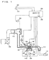
- the knock determination device of the present embodiment is implemented by a program executed, for example, by an engine ECU (Electronic Control Unit) 200.
- ECU Electronic Control Unit
- Engine 100 is an internal combustion engine, in which a mixture of air taken through an air cleaner 102 and a fuel injected by an injector 104 is ignited by a spark plug 106 and burned in a combustion chamber.
- the burning of air-fuel mixture causes combustion pressure that presses a piston 108 down, whereby a crank shaft 110 rotates.
- the combusted air-fuel mixture (or exhaust gas) is purified by a three-way catalyst 112 and thereafter discharged outside the vehicle.
- the amount of air taken into engine 110 is adjusted by a throttle valve 114.
- Engine 100 is controlled by engine ECU 200 having connected thereto a knock sensor 300, a water temperature sensor 302, a crank position sensor 306 arranged opposite a timing rotor 304, a throttle opening sensor 308, a vehicle speed sensor 310, and an ignition switch 312.
- Knock sensor 300 is implemented by a piezoelectric element. As engine 100 vibrates, knock sensor 300 generates a voltage having a magnitude corresponding to that of the vibration. Knock sensor 300 transmits a signal representing the voltage to engine ECU 200. Water temperature sensor 302 detects temperature of cooling water in engine 100 at a water jacket and transmits a signal representing a resultant detection to engine ECU 200.
- Timing rotor 304 is provided at a crank shaft 110 and rotates as crank shaft 110 does. Timing rotor 304 is circumferentially provided with a plurality of protrusions spaced by a predetermined distance. Crank position sensor 306 is arranged opposite the protrusions of timing rotor 304. When timing rotor 304 rotates, an air gap between the protrusions of timing rotor 304 and crank position sensor 306 varies, so that magnetic flux passing through a coil portion of crank position sensor increases/decreases, thus generating electromotive force. Crank position sensor 306 transmits a signal representing the electromotive force to engine ECU 200. From the signal transmitted from crank position sensor 306, engine ECU 200 detects a crank angle and the number of rotation of crank shaft 110.
- Throttle opening sensor 308 detects a throttle open position and transmits a signal representing a resultant detection to engine ECU 200.
- Vehicle speed sensor 310 detects number of rotation of a wheel (not shown) and transmits a signal representing a resultant detection to engine ECU 200. From the number of rotation of the wheel, engine ECU 200 calculates the vehicle speed.
- Ignition switch 312 is turned on by a driver, for starting engine 100.
- Engine ECU 200 uses the signals transmitted from each sensor and ignition switch 312 as well as a map and program stored in a memory 202 to perform an operation to control equipment so that engine 100 attains a desired driving condition.
- engine ECU 200 uses a signal transmitted from knock sensor 300 and a crank angle, detects a waveform of a vibration of engine 100 at a predetermined knock detection gate (a section from a predetermined first crank angle to a predetermined second crank angle) (hereinafter such waveform of a vibration will also simply be referred to as "vibration waveform") and from the detected vibration waveform determines whether engine 100 knocks.
- a predetermined knock detection gate a section from a predetermined first crank angle to a predetermined second crank angle
- vibration waveform a vibration waveform of a vibration will also simply be referred to as "vibration waveform”
- the knock detection gate of the present embodiment is from the top dead center (0°) to 90° in a combustion stroke. It is noted that the knock detection gate is not limited thereto.
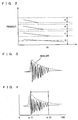
- vibrations occur in engine 100 at frequencies around the frequencies represented by solid lines in Fig. 2 . That is, when engine 100 knocks, the vibrations at frequencies included in a first frequency band A, a second frequency band B, a third frequency band C, and a fourth frequency band D occur.
- CA represents a crank angle.
- the number of frequency bands including the frequencies of a vibration attributed to knocking is not limited to four.
- fourth frequency band D includes a resonance frequency of engine 100 itself that is represented by an alternate-short-and-long dashed line in Fig. 2 . Vibration of resonance frequency generates regardless of presence/absence of knocking.
- a vibration waveform is detected based on the magnitudes of the vibrations of first to third frequency bands A to C not including the resonance frequency.
- the number of frequency bands used in detecting the vibration waveform is not limited to three. It is noted that in an engine less susceptible to resonance of the engine itself or the influence of mechanical noise, it may be unnecessary to select the frequency band.
- any known method may be adopted.
- the detected vibration waveform is compared with a knock waveform model, which will be described later.
- a memory 202 of engine ECU 200 stores a knock waveform model, which is a model vibration waveform when engine 100 knocks, as shown by a dotted line in Fig. 3 .
- magnitude of vibration is represented by a dimensionless number of 0 to 1 and does not uniquely correspond to a crank angle. More specifically, for the knock waveform model of the present embodiment, while it is determined that the vibration decreases in magnitude as the crank angle increases after the peak value in magnitude of vibration, the crank angle at which the vibration magnitude assumes the peak value is not determined.
- the knock waveform model is stored in memory 202 with the crank angle at which the vibration magnitude peaks being set to zero.
- the knock waveform model is an envelope of amplitude (vibration magnitude) of the synthesized wave (solid line) of the first to third frequency bands A to C.
- the method of calculating the envelope is not specifically limited and it may be calculated by any known technique. By way of example, it may be calculated by integrating the amplitude at every predetermined angle, or it may be calculated using root mean square (RMS) or Hilbert envelope.
- the envelope is calculated by integrating the amplitude of each of the first to third frequency bands A to C of the waveform obtained through an experiment or the like at every five degrees (5°), and by synthesizing the integrated values for the first to third frequency bands.
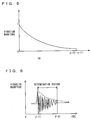
- the waveform of a section (dotted line) from an angle ⁇ (1) that corresponds to the peak value of vibration magnitude generated by knocking to an angle ⁇ (2) advanced by a predetermined angle therefrom is set as the knock waveform model.
- the knock waveform model is not limited to this section.
- the angles ⁇ (1) and ⁇ (2) may be both larger than or smaller than the angle that corresponds to the peak value of vibration waveform, and the waveform covering either the rising portion or attenuating portion of the vibration caused by knocking may be set as the knock waveform model.
- the waveform covering at least one of the rising portion and the attenuating portion of the vibration caused by knocking may be set as the knock waveform model.
- the knock waveform model is obtained as follows: an experiment or the like is conducted to force knocking of engine 100, and the vibration waveform of engine 100 is detected, from which the knock waveform model is created and stored in advance.
- the knock waveform model is not specifically limited to the envelope of amplitude of the synthesized wave of the first to third frequency bands A to C of the detected vibration corresponding to knocking, such as described above.
- the knock waveform model may be calculated by an equation that specifies an approximate waveform of an attenuating portion of the vibration corresponding to knocking, based on a predetermined attenuation factor.
- the knock waveform model that corresponds to the waveform of the section from the angle ⁇ (1) that corresponds to the peak value of vibration to the angle ⁇ (2) advanced by a predetermined angle therefrom shown in Fig. 4 may be formed.
- the knock waveform model may be formed by different methods.
- Engine ECU 200 compares the detected waveform with the stored knock waveform model, and determines whether engine 100 knocks or not.
- the section from the angle ⁇ (1) that corresponds to the peak value of waveform detected by knock sensor 300 to the angle ⁇ (2) advanced by a predetermined angle therefrom shown in Fig. 6 is used as the section for determining the knock waveform model.
- the determination section is defined to be within the knock detection gate and correspond to the set section of the knock determination model described above.
- Engine ECU 200 calculates the envelope (dotted line) of the amplitude of synthesized wave (solid line) of the first to third frequencies of the waveform detected by knock sensor 300.
- the method of calculating the envelope is the same as that for the knock waveform model, and therefore, detailed description thereof will not be repeated.
- the present invention is characterized in that engine ECU 200 determines whether knocking occurred in engine 100 or not based on a result of comparison between the knock waveform model stored in memory 202 and the detected waveform.
- the knock waveform model includes a plurality of knock waveform models corresponding to states of operation of engine 100.
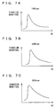
- vibration waveforms corresponding to knocking show different tendencies dependent on the number of rotation of crank shaft 110 of engine 100.
- the attenuating portion of the waveforms shown in Figs. 7A to 7C comes to be more moderate as the number of rotation becomes higher.
- Attenuation after the peak value of vibration corresponding to knocking has a component that depends on the crank angle and a component that depends on the real time. Therefore, when the crank shaft 110 rotates at high speed (with the number of rotation being high), the influence of the component dependent on the real time relatively increases and the influence of component dependent on the crank angle decreases, whereby the attenuation of waveform tends to be more moderate.
- engine ECU 200 detects the vibration magnitude of engine 100 from a signal transmitted from knock sensor 300.
- the vibration magnitude is represented by a value of voltage output from knock sensor 300.
- the vibration magnitude may be represented by a value corresponding to the value of the voltage output from knock sensor 300.
- the vibration magnitude is detected in a combustion stroke for an angle from a top dead center to (a crank angle of) 90°.
- engine ECU 200 calculates for a crank angle of every five degrees an integration (hereinafter also be referred to as an "integrated value") of values of voltage output from knock sensor 300 (i.e., representing magnitude of vibration).
- the integrated values are calculated for the vibration of each of the first to third frequency bands A to C.
- engine ECU 200 synthesizes the vibration waveforms of respective frequency bands. Specifically, from the calculated integrated values, integrated values of vibration in the first to third frequency bands A to C are synthesized. Thus, the envelope of amplitude of the vibration waveform of engine 100 is detected.
- engine ECU 200 normalizes the waveform using the largest of the integrated values of the synthesized vibration waveform.
- normalizing a waveform means dividing each integrated value by the largest of the integrated values in the detected waveform, for example, so that the vibration magnitude is represented by a dimensionless number of 0 to 1.
- the divisor of each integrated value is not limited to the largest of the integrated values.
- engine ECU 200 sets the knock waveform model. Specifically, engine ECU 200 senses the number of rotation of crank shaft 110 received from crank position sensor 306, and sets a knock waveform model that corresponds to the sensed number of rotation.
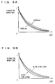
- a map such as shown in Fig. 9A is stored beforehand in memory 202, and ECU may interpolate and calculate the knock waveform model corresponding to the sensed number of rotation from the map.
- the values of attenuation factor ⁇ corresponding to rotation numbers of every 1000 rotations may be stored as a map in memory 202 as shown in Fig. 10A , and the attenuation factor ⁇ corresponding to the knock waveform model matching the number of rotation of crank shaft 110 received from crank position sensor 306 may be interpolated, to set the knock waveform model.
- a map such as shown in Fig.
- Attenuation factor ⁇ f1 (rotation number Ne) may be stored in advance, and the attenuation factor ⁇ may be calculated based on the sensed number of rotation Ne.
- the value of attenuation factor ⁇ has been described as calculated based on the number of rotation in the present embodiment, it may be calculated not based on the numb er of rotation.
- the waveform of vibration corresponding to knocking also tends to differ dependent on the load factor of engine 100.
- the load factor represents the ratio of actual intake air amount with respect to the intake air amount when engine 100 is at full load. Therefore, the load factor can be calculated based on the intake air amount sensed by an air flow meter (not shown) provided in the intake system of engine 100.
- the waveform of vibration corresponding to knocking comes to have more moderate attenuation portion as the load on crank shaft 100 of engine 100 increases (load factor increases), and comes to have steeper attenuation portion as the load decreases (load factor decreases).
- a map representing the relation between the load factor KL and the attenuation factor such as shown in Fig. 9B may be stored in memory 202, and by detecting the load factor from the intake air amount of engine 100, the value of attenuation factor ⁇ corresponding to the sensed load factor may be calculated from the map, to set the knock waveform model.
- the map is not limited to the one shown in Fig. 9B , and a map having load factor KL as the abscissa in place of number of rotation Ne such as shown in Fig. 10B may be stored.
- attenuation factor ⁇ may be stored as a function of load factor KL of engine 100.
- Attenuation factor ⁇ may be stored as a function of the number of rotation Ne and load factor KL of engine 100.
- a three-dimensional map (not shown) of attenuation factor ⁇ , number of rotation Ne and load factor KL may be stored beforehand, and attenuation factor ⁇ may be calculated based on the sensed number of rotation NE and sensed load factor KL.
- engine ECU 200 calculates a coefficient of correlation K, which is a value related to a deviation between the normalized vibration waveform and the knock waveform model.
- K is a value related to a deviation between the normalized vibration waveform and the knock waveform model.
- a timing of a normalized vibration waveform providing a vibration maximized in magnitude and a timing of a knock waveform model providing a vibration maximized in magnitude are matched, while a deviation in absolute value (or an amount of offset) between the normalized vibration waveform and the knock waveform model is calculated for each crank angle (of five degrees), whereby the coefficient of correlation K is obtained.
- engine ECU 200 calculates a knock intensity N.
- the BGL is stored in memory 202. Note that knock intensity N may be calculated by a different method.
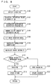
- engine ECU 200 determines whether knock intensity N is larger than a predetermined reference value. If the knock intensity N is larger than the predetermined reference value (YES at S 114), the control proceeds to S 116. Otherwise (NO at S114), the control proceeds to S120.
- engine ECU 200 determines that engine 100 knocks. At S118 engine ECU 200 introduces a spark retard. At S120 engine ECU 200 determines that engine 100 does not knock. At S126 engine ECU 200 introduces a spark advance.
- vibration magnitude of engine 100 is detected from a signal transmitted from knock sensor 300 (S100).
- the maximum integrated value is used to normalize the waveform (S106).
- each integrated value is divided by the integrated value from the angle ⁇ (1) to 5° and the vibration waveform is normalized.
- vibration magnitude in the vibration waveform is represented by a dimensionless number of 0 to 1.
- the detected vibration waveform can be compared with the knock waveform model regardless of the vibration magnitude. This can eliminate the necessity of storing a large number of knock waveform models corresponding to the magnitude of vibration and thus, facilitates preparation of the knock waveform model.
- a knock waveform model that corresponds to the number of rotation of crank shaft 110 sensed by crank position sensor 306 is set (S108), and as shown in Fig. 11 , a timing of a normalized vibration waveform providing a vibration maximized in magnitude and that of a knock waveform model providing a vibration maximized in magnitude are matched, while a deviation in absolute value ⁇ S (I) (hatched portion) between the normalized vibration waveform and the knock waveform model is calculated for each crank angle.
- the product of the calculated coefficient of correlation K and the largest integrated value P is divided by the BGL to calculate knock intensity N (S112).
- knock intensity N S112
- the product of coefficient of correlation K and the integrated value from the angle ⁇ (1) to 5° advanced therefrom is divided by BGL to calculate knock intensity N.
- knock intensity N is larger than a predetermined reference value (YES at S114) a determination is made that engine knocks (S116), and a spark retard is introduced (S 118) to suppress knocking.
- knock intensity N is not larger than the predetermined reference value (NO at S114)
- the engine ECU detects vibration waveform of the engine based on a signal transmitted from the knock sensor, and by comparing the vibration waveform with the knock waveform model, calculates a coefficient of correlation.
- a plurality of knock waveform models representing vibration waveforms when knocking occurs and corresponding to the engine speed are prepared and stored in advance, through an experiment or the like.
- By comparing the detected waveform with the waveform corresponding to the sensed engine speed among the stored plurality of knock waveform models it is possible to determine whether knocking has occurred or not. Therefore, it becomes possible to provide a knocking determination device that can accurately determine whether the knocking occurs or not in the internal combustion engine, by storing the plurality of knock waveform models corresponding to the engine speed and by comparing with the detected waveform.
- the shape of waveform particular to knocking can be determined with high accuracy.
- the shape of waveform particular to knocking can be determined with high accuracy, as the waveform of the portion including the peak value has high signal output.
- the amount of data to be stored beforehand can be reduced.
- the attenuation waveform after the peak value of vibration corresponding to knocking is calculated by approximation from a predetermined attenuation factor, what becomes necessary is simply to store the attenuation factor and the equation. Therefore, the amount of data to be stored beforehand can be reduced.
- a plurality of attenuation factors are stored, it becomes possible to determine whether the knocking occurs or not with high accuracy, by comparing the detected waveform and the waveform derived from the attenuation factor corresponding to the state of operation of the internal combustion engine.
- the knock waveform model may be stored in a memory as one waveform that has a shape particular to knocking and that does not change regardless of the type or state of operation of the internal combustion engine.
- whether the detected waveform represents vibration corresponding to knocking or not is determined by calculating the coefficient of correlation between the knock waveform model and the shape of the detected waveform to compare the two, while such an approach is not limiting and any other method may be used provided that the similarity between the two is given in a numerical value.
- a numerical value representing similarity between the knock waveform model and the detected waveform may be obtained through pattern matching, and whether the detected waveform corresponds to vibration of knocking or not may be determined. Specific method of pattern matching has been known, and therefore, detailed description will not be given here.
Landscapes
- Chemical & Material Sciences (AREA)
- Engineering & Computer Science (AREA)
- Combustion & Propulsion (AREA)
- Physics & Mathematics (AREA)
- General Physics & Mathematics (AREA)
- Combined Controls Of Internal Combustion Engines (AREA)
- Measurement Of Mechanical Vibrations Or Ultrasonic Waves (AREA)
Description
- The present invention relates to a knocking determination device and, more specifically, to a knocking determination device for an internal combustion engine that determines whether knocking occurs or not, based on vibration waveform of the internal combustion engine.
- Conventionally, a technique for detecting knocking of an internal combustion engine is known. Japanese Patent Laying-Open No.
2001-227400 - According to the knock control device for an internal combustion engine disclosed in the publication, a signal representing a waveform of vibration occurring in the internal combustion engine is detected by a signal detector. An occurrence period during which the vibration waveform signal assumes a predetermined value or higher and a peak position therein are detected by an occurrence period detector and a peak position detector, respectively. Thus, the knock determiner can determine whether the engine knocks by detecting the position of the peak in the occurrence period of the vibration waveform signal. According to the knock determination result, the operation state of the internal combustion engine is controlled. When the peak position relative to the occurrence period is in a predetermined range, that is, when a waveform has such a shape that the peak position appears earlier relative to a predetermined length of the occurrence period of the vibration waveform signal, the knock determiner recognizes it as being particular to knocking. Thus, even in a transition state where an operation state of the internal combustion engine abruptly changes or when electric loads are turned on/off, whether or not the internal combustion engine knocks is accurately determined, and the operation state of the internal combustion engine can be controlled appropriately.
- However, while the engine knocks, a vibration that is greater in magnitude than a vibration attributed to knocking may sometimes be detected as noise. That is, in some cases a vibration attributed to a fault of a knock sensor or attributed to a vibration of the internal combustion engine itself may be greater in magnitude than a vibration attributed to knocking. In such cases, with the knock control device for an internal combustion engine of Japanese Patent Laying-Open No.
2001-227400 - Document
EP-A-0 889 309 discloses a device for detecting and measuring knocking and an anti-knock control system using the same. The device for detection and measurement of pinking in an internal combustion engine has an acoustic emission sensor attached to the cylinder head, which supplies an electronic signal to an amplification and filtering circuit, which in turn is connected to a processing circuit for treatment of the signal from the sensor. The output from the processing circuit can be used with an anti-pinking mechanism that controls fuel injection to the engine. The processing electronics comprises a circuit, which applies a time window to the sensor, so that only data around top dead centre are considered, a rectifying circuit and an integrating circuit, of which the output amplitude is proportional to the degree of pinking. - Document
EP-A-0 454 486 discloses a method and apparatus of detecting knocking in an internal combustion engine having a crankshaft, which uses a knock detecting sensor to detect vibration caused by knocking. The signals from the knock detecting sensor are detected between a first and a second moment of time (i.e. a measurement window) and at least one of the first and second moments of time are independently varied in dependence upon a vibration spectrum of frequencies to be detected. In a preferred embodiment a plurality of frequency spectra, each having a different first and second moment of time, are each separately analysed for determining knock intensity. The moments of time are represented by first and second angles of the crankshaft. A plurality of measurement windows are used to determine the level of knocking and if the level exceeds a predetermined level the ignition timing for the engine is retarded. The frequency of maximum amplitude is arranged in operation to be the centre frequency of a frequency spectrum determined by the measurement window. - Document
US-A-5 537 855 discloses a knock detection method and an apparatus with dual integration windows. The knock detection method and apparatus integrates a knock sensor signal over a first period and provides a first integrated knock sensor signal, and integrates the knock sensor signal over a second period and provides a second integrated knock sensor signal. A knock indication is provided dependent on an amplitude of the first integrated knock sensor signal and an amplitude of the second integrated knock sensor signal and independent of the influence of the variations of the knock sensor potential sensor to sensor gain variation. - Document
US-A-5 343 843 discloses a knock control for high speed engine including a knock burst envelope follower. An ignition system for a vehicle engine has a fast response knock control which generates a rectified knock sensor signal having peaks at a knock frequency in accordance with the knock induced engine vibrations and samples and holds the voltage at each consecutive peak to generate a knock burst envelope signal in which knock burst envelopes correspond in amplitude and duration to knock vibration bursts in the knock sensor signal without phase shift induced group delay. The fast response is preserved in a fast response DC noise reference and an output which provides pulses at a frequency increasing with amplitude of the knock burst envelopes. -
Document DE 102 5 959 discloses a method for detecting knocking in petrol-driven external combustion engines, whereby the pressure in the combustion chamber is measured over the combustion cycle and the onset of knocking detected as high frequency variations superimposed on the cylinder pressure signal, and a device for detecting knocking in a petrol engine. The device comprises a cylinder head pressure sensor and a computer connected to the output signal for signal analysis purposes. - Document
EP-A-0 732 573 discloses a method and a device for recognizing vibration signals, e.g. knocking of internal combustion engines. The method involves selecting required data on engine parameters from a mapped table. The data is passed to a decoder in a separate memory. The decoded data is sent to a second memory. A reference signal is generated for use as one input to a multiplier. A vibration detector signal is used as the other input to the multiplier. The multiplied signal is then rectified. The rectified signal is integrated. The integrator is then set to zero with a signal from the decoder. A presence or absence of the signal is determined based upon a comparison of the integrated signal with a given threshold. - Document
EP-A-1 221 603 discloses a knock / misfire detection by wavelet transform. There is described a system for detection of combustion anomalies in an internal combustion engine, including a crank angle indicator, a vibration sensor, and a signal processor, wherein the signal processor receives signals from the indicator and the sensor, wherein a wavelet transform analysis of the signals from the sensor is performed to develop a vibration frequency signature on a time scale, the vibration frequency signature is compared to a predetermined value to determine the existence of anomalies in the combustion process, and the time scale of the vibration frequency signature is compared to the signal from the indicator to determine which of a plurality of cylinders of the internal combustion engine is exhibiting the combustion anomaly. DocumentDE 103 43 146 discloses a method of detecting cylinder pressure and/or faulty ignition and/or knock in an internal combustion engine with sensors involving processing signals of revolution rate sensors interacting with crankshaft and/or camshaft in a real-time controller. The method involves acquiring and processing the sensor signals of the revolution rate sensors interacting with the crankshaft and/or camshaft with a real-time controller, comparing current and previous signal pauses or periodic duration and relating the ratios or differences to values determined using a characteristic field or an algorithm. There is also provided a device for detecting cylinder pressure and/or faulty ignition and/or knocking in an internal combustion engine with sensors. - Document
US-2004-0162668 discloses a knock detection system using waveform shape descriptors (WSDs). A time-varying signal is provided by an accelerometer from which a stream of WSDs is generated. The stream of WSDs is used to generate a matrix which is compared against archetype matrices to determine a knock level. - An object of the present invention is to provide a knock determination device that can determine whether the engine knocks with high accuracy.
- This object is achieved by a knock determination device according to
claim 1, claim 6, claim 14 or claim 17. Advantageous further developments are as set forth in the respective dependent claims. - According to an aspect, there is provided a knocking determination device for determining knocking of an internal combustion engine. The knocking determination device includes: a crank angle detecting unit detecting a crank angle of the internal combustion engine; a waveform detecting unit detecting a vibration waveform of the internal combustion engine between predetermined crank angles; a storage unit storing in advance one waveform representing vibration waveform corresponding t o knocking that does not change regardless of type and state of operation of the internal combustion engine; and a determining unit determining whether knocking occurred in the internal combustion engine or not, based on a result of comparison between the detected waveform and the waveform stored in the storage unit.
- According to one aspect, the crank angle detecting unit detects the crank angle of the internal combustion engine, and the waveform detecting unit detects the waveform of vibration of the internal combustion engine between predetermined crank angles. The storage unit stores in advance one waveform of vibration corresponding to knocking, which does not change regardless of the type and state of operation of the internal combustion engine. Based on the result of comparison between the detected waveform and the stored waveform, whether the internal combustion engine knocks or not is determined. Accordingly, if it is possible, for example, to specify a vibration waveform corresponding to one knocking that does not change dependent on the type and state of operation of the internal combustion engine, a knock waveform model as the vibration waveform that appears when knocking occurs may be formed and stored in advance, and by comparing the knock waveform model and the detected waveform, whether knocking occurred or not can be determined. Further, the knock waveform model is one waveform that does not change dependent on the type and state of operation of the internal combustion engine. Therefore it becomes unnecessary to store a plurality of knock waveform models for different types and different states of operation of the internal combustion engine, and thus, the amount of data to be stored beforehand can be reduced. Further, it is unnecessary to set a plurality of knock waveform models for different types of internal combustion engine, and hence, the time necessary for setting can be made shorter. Therefore, a knocking determination device that can accurately determine whether the knocking occurs or not in the internal combustion engine while enabling reduction in data amount to be stored beforehand can be provided.
- According to another aspect, there is provided a knocking determination device for determining knocking of an internal combustion engine. The knocking determination device includes: a crank angle detecting unit detecting a crank angle of the internal combustion engine; a waveform detecting unit detecting a vibration waveform of the internal combustion engine between predetermined crank angles; a storage unit storing in advance a plurality of vibration waveforms of the internal combustion engine corresponding to states of operation of the internal combustion engine; and a determining unit determining whether knocking occurred in the internal combustion engine or not, based on a result of comparison between the detected waveform and a waveform corresponding to the state of operation of the internal combustion engine among the plurality of waveforms stored in the storage unit.
- According to an aspect, the crank angle detecting unit detects the crank angle of the internal combustion engine, and the waveform detecting unit detects the waveform of vibration of the internal combustion engine between predetermined crank angles. The storage unit stores a plurality of vibration waveforms of the internal combustion engine that correspond to states of operation (such as the number of rotation of crank shaft) of the internal combustion engine. Based on the result of comparison between the detected waveform and the stored waveform, whether the internal combustion engine knocks or not is determined. Specifically, a plurality of knock waveform models representing vibration waveforms when knocking occurs, which correspond to the states of operations, are prepared through an experiment or the like and stored in advance. By comparing the detected waveform with one of the stored plurality of knock waveform models, which corresponds to the state of operation, whether knocking occurred or not can be determined. Vibration corresponding to knocking may have different tendency dependent on the state of operation of the internal combustion engine that varies with time. Therefore, by storing a plurality of knock waveform models corresponding to the states of operation of internal combustion engine, it becomes possible to provide a knocking determination device that can accurately determine whether the knocking occurs or not in the internal combustion engine.
- Preferably, the knocking determination device further includes a rotation number sensing unit sensing the number of rotation of an output shaft of the internal combustion engine. The storage unit stores in advance a plurality of vibration waveforms corresponding to the number of rotation. The determining unit determines whether knocking occurred in the internal combustion engine or not, based on a result of comparison between the detected waveform and a waveform stored in the storage unit corresponding to the sensed number of rotation.
- According to an aspect, the storage unit stores a plurality of vibration waveforms corresponding to the number of rotation of the output shaft of the internal combustion engine (crank shaft of the engine) obtained, by way of example, through an experiment. By comparing the detected waveform and the waveform that corresponds to the sensed number of rotation among the stored plurality of waveforms, it is possible to determine whether the knocking occurs or not in the internal combustion engine with high accuracy.
- More preferably, the knocking determination device further includes a load factor sensing unit sensing a load factor of the internal combustion engine. The storage unit stores in advance a plurality of vibration waveforms corresponding to the load factor. The determining unit determines whether knocking occurred in the internal combustion engine or not, based on a result of comparison between the detected waveform and the waveform stored in the storage unit corresponding to the sensed load factor.
- According to an aspect, the storage unit stores a plurality of vibration waveforms corresponding to the load factors of the internal combustion engine obtained, by way of example, through an experiment. By comparing the detected waveform and the waveform that corresponds to the sensed load factor among the stored plurality of waveforms, it is possible to determine whether the knocking occurs or not in the internal combustion engine with high accuracy.
- More preferably, the knocking determination device further includes a rotation number sensing unit sensing the number of rotation of an output shaft of the internal combustion engine and a load factor sensing unit sensing a load factor of the internal combustion engine. The storage unit stores in advance a plurality of vibration waveforms corresponding to the number of rotation and the load factor. The determining unit determines whether knocking occurred in the internal combustion engine or not, based on a result of comparison between the detected waveform and the waveform stored in the storage unit corresponding to the sensed number of rotation and the sensed load factor.
- According to an aspect, the storage unit stores a plurality of vibration waveforms corresponding to the number of rotation of the output shaft of the internal combustion engine (crank shaft of the engine) and to the load factors, obtained, by way of example, through an experiment. By comparing the detected waveform and the waveform that corresponds to the sensed number of rotation and load factor among the stored plurality of waveforms, it is possible to determine whether the knocking occurs or not in the internal combustion engine with high accuracy.
- More preferably, the waveform stored in the storage unit is a waveform of a section between a first angle and a second angle. The first and second angles are both larger than, or both smaller than an angle that corresponds to a peak value of vibration waveform.
- According to an aspect, as the first and second angles are both larger or both smaller than the angle that corresponds to the peak value of vibration waveform, either the rising portion or attenuating portion of the vibration waveform can be used as the knock waveform model. Therefore, by comparing the knock waveform model with the waveform of either the rising portion or attenuating portion of the detected waveform, the shape of waveform particular to knocking can be determined with high accuracy. Further, only the characteristic portion of vibration corresponding to knocking is stored, and therefore, the mount of data to be stored beforehand can b e reduced.
- More preferably, the waveform stored in the storage unit is a waveform of a section between a first angle and a second angle. The section includes an angle that corresponds to a peak value of vibration waveform.
- According to an aspect, the storage unit stores the waveform of a section between the first angle that corresponds to the peak value of vibration waveform and the second angle, and therefore, a waveform covering at least one of the rising portion and attenuating portion of the vibration waveform including the peak value can be used as the knock waveform model. Therefore, by comparing the knock waveform model with the waveform of the corresponding section, the shape of waveform particular to knocking can be determined with high accuracy, as the waveform of the portion including the peak value has high signal output. Further, only the characteristic portion of vibration corresponding to knocking is stored, and therefore, the amount of data to be stored beforehand can be reduced.
- More preferably, the first angle is an angle corresponding to the peak value of vibration waveform.
- According to an aspect, the first angle corresponds to the peak value of the vibration waveform. Specifically, the waveform covering at least one of the rising portion and attenuating portion of the vibration waveform including the peak value can be used as the knock waveform model. Therefore, by comparing the knock waveform model with the waveform of the corresponding section, the shape of waveform particular to knocking can be determined with high accuracy, as the waveform of the portion including the peak value has high signal output.
- More preferably, the second angle is an angle advance by a predetermined angle from the first angle.
- According to an aspect, the second angle is an angle advanced by a predetermined angle from the first angle that corresponds to the peak value of the vibration waveform. Specifically, by storing the waveform of the section from the first angle corresponding to the peak value of the vibration waveform to the second angle, the attenuating portion of the vibration waveform including the peak value can be used as the knock waveform model. Therefore, by comparing the knock waveform model with the detected waveform of the attenuating portion including the peak value, the shape of waveform particular to knocking can be determined with high accuracy, as the waveform of the portion including the peak value has high signal output.
- According to another aspect, there is provided a knocking determination device for determining knocking of an internal combustion engine. The knocking determination device includes: a crank angle detecting unit detecting a crank angle of the internal combustion engine; a waveform detecting unit detecting a vibration waveform of the internal combustion engine between predetermined crank angles; a storage unit storing in advance an envelope of amplitude of vibration waveform corresponding to knocking; and a determining unit determining whether knocking occurred in the internal combustion engine or not, based on a result of comparison between the detected waveform and storey envelope.
- According to an aspect, the crank angle detecting unit detects the crank angle of the internal combustion engine, and the waveform detecting unit detects the waveform of vibration of the internal combustion engine between predetermined crank angles. The storage unit stores in advance an envelope of amplitude of a vibration waveform that corresponds to knocking. Based on the result of comparison between the detected waveform and the stored envelope, whether the internal combustion engine knocks or not is determined. Specifically, a knock waveform model is prepared based on the envelope of amplitude of the vibration waveform when knocking occurs, through an experiment or the like, and stored in advance. By comparing the detected waveform with the stored envelope, whether knocking occurred or not can be determined. Therefore, whether or not the engine knocks can be determined based not only on the magnitude of vibration of the internal combustion engine but also on the crank angle at which vibration occurs. Further, the envelope of amplitude after the peak value of vibration waveform has a vibration attenuation curve particular to knocking. Therefore, it becomes possible to provide a knocking determination device that can accurately determine whether the knocking occurs or not in the internal combustion engine, by comparing the detected waveform with the knock waveform model.
- According to another aspect, there is provided a knocking determination device for determining knocking of an internal combustion engine. The knocking determination device includes: a crank angle detecting unit detecting a crank angle of the internal combustion engine; a waveform detecting unit detecting a vibration waveform of the internal combustion engine between predetermined crank angles; a storage unit storing in advance a predetermined attenuation factor after an angle corresponding to the peak value of vibration waveform of the internal combustion engine; and a determining unit determining whether knocking occurred in the internal combustion engine or not, based on a result of comparison between the detected waveform and a waveform derived from the stored attenuation factor.
- According to an aspect, the crank angle detecting unit detects the crank angle of the internal combustion engine, and the waveform detecting unit detects the waveform of vibration of the internal combustion engine between predetermined crank angles. The storage unit stores in advance a predetermined attenuation factor after the angle that corresponds to the peak value of vibration waveform of the internal combustion engine. Based on the result of comparison between the detected waveform and the waveform derived from the stored attenuation factor, whether the internal combustion engine knocks or not is determined. Specifically, the attenuation factor after the angle that corresponds to the peak value of vibration waveform when knocking occurs is stored in advance through an experiment or the like, and by comparing the detected waveform with the waveform derived from the stored attenuation factor, whether knocking occurred or not can be determined. Therefore, whether or not the engine knocks can be determined based not only on the magnitude of vibration of the internal combustion engine but also on the crank angle at which vibration occurs. Further, from the predetermined attenuation factor, the attenuating waveform after the peak value of vibration corresponding to knocking can be calculated by approximation, and therefore, the amount of data to be stored beforehand can be reduced. Alternatively, by storing a plurality of attenuation factors, it becomes possible to provide a knocking determination device that can accurately determine whether the knocking occurs or not in the internal combustion engine, by comparing the detected waveform with the waveform derived from the attenuation factor that corresponds to the state of operation of the internal combustion engine.
- Preferably, the waveform stored in the storage unit is a waveform of a section between a first angle and a second angle. The first angle is an angle corresponding to the peak value of vibration waveform
- According to an aspect, as the storage unit stores the waveform of the section between the first angle corresponding to the peak value of vibration waveform and the second angle, the attenuating portion of the vibration waveform including the peak value can be used as the knock waveform model. Therefore, by comparing the knock waveform model with the waveform of the attenuating portion including the peak value of the detected waveform, the shape of waveform particular to knocking can be determined with high accuracy, as the waveform of the portion including the peak value has high signal output. Further, only the characteristic portion of vibration corresponding to knocking is stored, and therefore, the amount of data to be stored beforehand can be reduced.
- More preferably, the second angle is an angle advance by a predetermined angle from the first angle.
- According to an aspect, the second angle is an angle advanced by a predetermined angle from the first angle that corresponds to the peak value of the vibration waveform. Specifically, by storing the waveform of the section from the first angle corresponding to the peak value of the vibration waveform to the second angle, the attenuating portion of the vibration waveform including the peak value can be used as the knock waveform model. Therefore, by comparing the knock waveform model with the detected waveform of the attenuating portion including the peak value, the shape of waveform particular to knocking can be determined with high accuracy, as the waveform of the portion including the peak value has high signal output.
-
-
Fig. 1 is a schematic configuration diagram showing an engine controlled by a knock determination device according to an embodiment of the present invention. -
Fig. 2 is a diagram representing frequencies of vibrations occurring in the engine. -
Fig. 3 represents knock waveform model (1). -
Fig. 4 represents a section that defines the knock waveform model. -
Fig. 5 represents knock waveform model (2). -
Fig. 6 represents a vibration waveform sensed by the knock sensor. -
Figs. 7A to 7C show vibration waveforms at different engine speed. -
Fig. 8 is a flowchart illustrating a control structure of a program executed by the engine ECU. -
Figs. 9A and 9B represent knock waveform models corresponding to the engine speed. -
Figs. 10A and 10B represent relation between engine speed and attenuation factor. -
Fig. 11 is a diagram representing timings for comparing the normalized vibration waveform with the knock waveform model. - Embodiments of the present invention will be described in the following with reference to the figures. In the following description, the same components are denoted by the same reference characters. The names and functions are also the same. Therefore, detailed description thereof will not be repeated.
- With reference to
Fig. 1 , anengine 100 of a vehicle incorporating a knock determination device according to an embodiment of the present invention will be described. The knock determination device of the present embodiment is implemented by a program executed, for example, by an engine ECU (Electronic Control Unit) 200. -
Engine 100 is an internal combustion engine, in which a mixture of air taken through anair cleaner 102 and a fuel injected by an injector 104 is ignited by aspark plug 106 and burned in a combustion chamber. - The burning of air-fuel mixture causes combustion pressure that presses a
piston 108 down, whereby acrank shaft 110 rotates. The combusted air-fuel mixture (or exhaust gas) is purified by a three-way catalyst 112 and thereafter discharged outside the vehicle. The amount of air taken intoengine 110 is adjusted by athrottle valve 114. -
Engine 100 is controlled byengine ECU 200 having connected thereto aknock sensor 300, awater temperature sensor 302, a crankposition sensor 306 arranged opposite atiming rotor 304, athrottle opening sensor 308, avehicle speed sensor 310, and anignition switch 312. -
Knock sensor 300 is implemented by a piezoelectric element. Asengine 100 vibrates, knocksensor 300 generates a voltage having a magnitude corresponding to that of the vibration.Knock sensor 300 transmits a signal representing the voltage toengine ECU 200.Water temperature sensor 302 detects temperature of cooling water inengine 100 at a water jacket and transmits a signal representing a resultant detection toengine ECU 200. - Timing
rotor 304 is provided at acrank shaft 110 and rotates as crankshaft 110 does. Timingrotor 304 is circumferentially provided with a plurality of protrusions spaced by a predetermined distance. Crankposition sensor 306 is arranged opposite the protrusions oftiming rotor 304. When timingrotor 304 rotates, an air gap between the protrusions oftiming rotor 304 and crankposition sensor 306 varies, so that magnetic flux passing through a coil portion of crank position sensor increases/decreases, thus generating electromotive force. Crankposition sensor 306 transmits a signal representing the electromotive force toengine ECU 200. From the signal transmitted from crankposition sensor 306,engine ECU 200 detects a crank angle and the number of rotation ofcrank shaft 110. -
Throttle opening sensor 308 detects a throttle open position and transmits a signal representing a resultant detection toengine ECU 200.Vehicle speed sensor 310 detects number of rotation of a wheel (not shown) and transmits a signal representing a resultant detection toengine ECU 200. From the number of rotation of the wheel,engine ECU 200 calculates the vehicle speed.Ignition switch 312 is turned on by a driver, for startingengine 100. -
Engine ECU 200 uses the signals transmitted from each sensor andignition switch 312 as well as a map and program stored in amemory 202 to perform an operation to control equipment so thatengine 100 attains a desired driving condition. - In the present embodiment, using a signal transmitted from
knock sensor 300 and a crank angle,engine ECU 200 detects a waveform of a vibration ofengine 100 at a predetermined knock detection gate (a section from a predetermined first crank angle to a predetermined second crank angle) (hereinafter such waveform of a vibration will also simply be referred to as "vibration waveform") and from the detected vibration waveform determines whetherengine 100 knocks. The knock detection gate of the present embodiment is from the top dead center (0°) to 90° in a combustion stroke. It is noted that the knock detection gate is not limited thereto. - When the engine knocks, vibrations occur in
engine 100 at frequencies around the frequencies represented by solid lines inFig. 2 . That is, whenengine 100 knocks, the vibrations at frequencies included in a first frequency band A, a second frequency band B, a third frequency band C, and a fourth frequency band D occur. InFig. 2 , CA represents a crank angle. The number of frequency bands including the frequencies of a vibration attributed to knocking is not limited to four. - Of these frequency bands, fourth frequency band D includes a resonance frequency of
engine 100 itself that is represented by an alternate-short-and-long dashed line inFig. 2 . Vibration of resonance frequency generates regardless of presence/absence of knocking. - Therefore, in the present embodiment, a vibration waveform is detected based on the magnitudes of the vibrations of first to third frequency bands A to C not including the resonance frequency. The number of frequency bands used in detecting the vibration waveform is not limited to three. It is noted that in an engine less susceptible to resonance of the engine itself or the influence of mechanical noise, it may be unnecessary to select the frequency band. As to the method of extracting frequency band, any known method may be adopted. The detected vibration waveform is compared with a knock waveform model, which will be described later.
- In order to determine whether a knock occurred or not, a
memory 202 ofengine ECU 200 stores a knock waveform model, which is a model vibration waveform whenengine 100 knocks, as shown by a dotted line inFig. 3 . - In the knock waveform model, magnitude of vibration is represented by a dimensionless number of 0 to 1 and does not uniquely correspond to a crank angle. More specifically, for the knock waveform model of the present embodiment, while it is determined that the vibration decreases in magnitude as the crank angle increases after the peak value in magnitude of vibration, the crank angle at which the vibration magnitude assumes the peak value is not determined. In the present embodiment, the knock waveform model is stored in
memory 202 with the crank angle at which the vibration magnitude peaks being set to zero. - The knock waveform model is an envelope of amplitude (vibration magnitude) of the synthesized wave (solid line) of the first to third frequency bands A to C. The method of calculating the envelope is not specifically limited and it may be calculated by any known technique. By way of example, it may be calculated by integrating the amplitude at every predetermined angle, or it may be calculated using root mean square (RMS) or Hilbert envelope. In the present embodiment, the envelope is calculated by integrating the amplitude of each of the first to third frequency bands A to C of the waveform obtained through an experiment or the like at every five degrees (5°), and by synthesizing the integrated values for the first to third frequency bands.
- In the present embodiment, referring to
Fig. 4 , of the waveform obtained through an experiment, for example, the waveform of a section (dotted line) from an angle α (1) that corresponds to the peak value of vibration magnitude generated by knocking to an angle α (2) advanced by a predetermined angle therefrom is set as the knock waveform model. The knock waveform model is not limited to this section. For instance, the angles α (1) and α (2) may be both larger than or smaller than the angle that corresponds to the peak value of vibration waveform, and the waveform covering either the rising portion or attenuating portion of the vibration caused by knocking may be set as the knock waveform model. Alternatively, the waveform covering at least one of the rising portion and the attenuating portion of the vibration caused by knocking may be set as the knock waveform model. - The knock waveform model is obtained as follows: an experiment or the like is conducted to force knocking of
engine 100, and the vibration waveform ofengine 100 is detected, from which the knock waveform model is created and stored in advance. - It is noted that the knock waveform model is not specifically limited to the envelope of amplitude of the synthesized wave of the first to third frequency bands A to C of the detected vibration corresponding to knocking, such as described above. For instance, the knock waveform model may be calculated by an equation that specifies an approximate waveform of an attenuating portion of the vibration corresponding to knocking, based on a predetermined attenuation factor. Specifically, referring to
Fig. 5 , the attenuation waveform of vibration corresponding to knocking can be represented in approximation by an equation of exponential function: (vibration magnitude) = exp (-λ x crank angle), where λ represents attenuation factor (logarithmic decrement). Therefore, only the attenuation factor λ and the equation above have to be stored in advance inmemory 202. In this manner also, the knock waveform model that corresponds to the waveform of the section from the angle α (1) that corresponds to the peak value of vibration to the angle α (2) advanced by a predetermined angle therefrom shown inFig. 4 may be formed. The knock waveform model may be formed by different methods. -
Engine ECU 200 compares the detected waveform with the stored knock waveform model, and determines whetherengine 100 knocks or not. - In the present embodiment, the section from the angle β (1) that corresponds to the peak value of waveform detected by
knock sensor 300 to the angle β (2) advanced by a predetermined angle therefrom shown inFig. 6 is used as the section for determining the knock waveform model. The determination section is defined to be within the knock detection gate and correspond to the set section of the knock determination model described above. -
Engine ECU 200 calculates the envelope (dotted line) of the amplitude of synthesized wave (solid line) of the first to third frequencies of the waveform detected byknock sensor 300. The method of calculating the envelope is the same as that for the knock waveform model, and therefore, detailed description thereof will not be repeated. - The present invention is characterized in that
engine ECU 200 determines whether knocking occurred inengine 100 or not based on a result of comparison between the knock waveform model stored inmemory 202 and the detected waveform. - It is noted that, in the present embodiment, the knock waveform model includes a plurality of knock waveform models corresponding to states of operation of
engine 100. As shown inFigs. 7A to 7C , vibration waveforms corresponding to knocking show different tendencies dependent on the number of rotation ofcrank shaft 110 ofengine 100. Particularly, the attenuating portion of the waveforms shown inFigs. 7A to 7C comes to be more moderate as the number of rotation becomes higher. Attenuation after the peak value of vibration corresponding to knocking has a component that depends on the crank angle and a component that depends on the real time. Therefore, when thecrank shaft 110 rotates at high speed (with the number of rotation being high), the influence of the component dependent on the real time relatively increases and the influence of component dependent on the crank angle decreases, whereby the attenuation of waveform tends to be more moderate. - Referring to
Fig. 8 , the control structure of the program executed byengine ECU 200 in the knocking determination device in accordance with the present embodiment will be described. - At step (hereinafter simply referred to as "S") 100,
engine ECU 200 detects the vibration magnitude ofengine 100 from a signal transmitted fromknock sensor 300. The vibration magnitude is represented by a value of voltage output fromknock sensor 300. Note that the vibration magnitude may be represented by a value corresponding to the value of the voltage output fromknock sensor 300. The vibration magnitude is detected in a combustion stroke for an angle from a top dead center to (a crank angle of) 90°. - At S102,
engine ECU 200 calculates for a crank angle of every five degrees an integration (hereinafter also be referred to as an "integrated value") of values of voltage output from knock sensor 300 (i.e., representing magnitude of vibration). The integrated values are calculated for the vibration of each of the first to third frequency bands A to C. - At S104,
engine ECU 200 synthesizes the vibration waveforms of respective frequency bands. Specifically, from the calculated integrated values, integrated values of vibration in the first to third frequency bands A to C are synthesized. Thus, the envelope of amplitude of the vibration waveform ofengine 100 is detected. - At S106,
engine ECU 200 normalizes the waveform using the largest of the integrated values of the synthesized vibration waveform. Here, normalizing a waveform means dividing each integrated value by the largest of the integrated values in the detected waveform, for example, so that the vibration magnitude is represented by a dimensionless number of 0 to 1. The divisor of each integrated value is not limited to the largest of the integrated values. - At S108,
engine ECU 200 sets the knock waveform model. Specifically,engine ECU 200 senses the number of rotation ofcrank shaft 110 received from crankposition sensor 306, and sets a knock waveform model that corresponds to the sensed number of rotation. By way of example, a map such as shown inFig. 9A is stored beforehand inmemory 202, and ECU may interpolate and calculate the knock waveform model corresponding to the sensed number of rotation from the map. - Alternatively, when the approximated waveform calculated by the predetermined attenuation factor λ and the exponential equation as described with reference to
Fig. 5 is used as the knock waveform model, the values of attenuation factor λ corresponding to rotation numbers of every 1000 rotations may be stored as a map inmemory 202 as shown inFig. 10A , and the attenuation factor λ corresponding to the knock waveform model matching the number of rotation ofcrank shaft 110 received from crankposition sensor 306 may be interpolated, to set the knock waveform model. Alternatively, a map such as shown inFig. 10B may be stored beforehand inmemory 202, and the value of attenuation factor λ corresponding to the sensed number of rotation may be calculated from the map, to set the knock waveform model, or the attenuation factor λ may be stored as a function. Sp ecifically, a function expression of attenuation factor λ = f1 (rotation number Ne) may be stored in advance, and the attenuation factor λ may be calculated based on the sensed number of rotation Ne. - Further, though the value of attenuation factor λ has been described as calculated based on the number of rotation in the present embodiment, it may be calculated not based on the numb er of rotation. By way of example, the waveform of vibration corresponding to knocking also tends to differ dependent on the load factor of
engine 100. The load factor represents the ratio of actual intake air amount with respect to the intake air amount whenengine 100 is at full load. Therefore, the load factor can be calculated based on the intake air amount sensed by an air flow meter (not shown) provided in the intake system ofengine 100. - As shown in
Fig. 9B , the waveform of vibration corresponding to knocking comes to have more moderate attenuation portion as the load on crankshaft 100 ofengine 100 increases (load factor increases), and comes to have steeper attenuation portion as the load decreases (load factor decreases). - Therefore, a map representing the relation between the load factor KL and the attenuation factor such as shown in
Fig. 9B may be stored inmemory 202, and by detecting the load factor from the intake air amount ofengine 100, the value of attenuation factor λ corresponding to the sensed load factor may be calculated from the map, to set the knock waveform model. - The map is not limited to the one shown in
Fig. 9B , and a map having load factor KL as the abscissa in place of number of rotation Ne such as shown inFig. 10B may be stored. Alternatively, attenuation factor λ may be stored as a function of load factor KL ofengine 100. Specifically, the function expression of attenuation factor λ = f2 (load factor KL) may be stored beforehand, and the attenuation factor λ may be calculated based on the sensed load factor KL. - Alternatively, attenuation factor λ may be stored as a function of the number of rotation Ne and load factor KL of
engine 100. Specifically, the function expression of attenuation factor λ = f3 (number of rotation Ne, load factor KL) may be stored beforehand, and the attenuation factor λ may be calculated based on the sensed number of rotation NE and sensed load factor KL. A three-dimensional map (not shown) of attenuation factor λ, number of rotation Ne and load factor KL may be stored beforehand, and attenuation factor λ may be calculated based on the sensed number of rotation NE and sensed load factor KL. - At S110,
engine ECU 200 calculates a coefficient of correlation K, which is a value related to a deviation between the normalized vibration waveform and the knock waveform model. A timing of a normalized vibration waveform providing a vibration maximized in magnitude and a timing of a knock waveform model providing a vibration maximized in magnitude are matched, while a deviation in absolute value (or an amount of offset) between the normalized vibration waveform and the knock waveform model is calculated for each crank angle (of five degrees), whereby the coefficient of correlation K is obtained. - When we represent the absolute value of deviation between the normalized vibration waveform and the knock waveform model for each crank angle by ΔS (I) (wherein I is a natural number) and the vibration magnitude of knock waveform model integrated by the crank angle (i.e., the area of knock waveform model) by S, then the coefficient of correlation K is calculated by an equation K = (S - ∑ΔS (I))/S, where ∑ΔS (I) represents a sum of ΔS (I)s. Note that the coefficient of correlation K may be calculated by a different method.
- At S112,
engine ECU 200 calculates a knock intensity N. When we represent the maximum value of calculated integrated value by P and the value representing the magnitude of vibration ofengine 100 whileengine 100 is not knocking by BGL (Back Ground Level), the knock intensity N is calculated by the equation N = P x K / BGL. The BGL is stored inmemory 202. Note that knock intensity N may be calculated by a different method. - At S114,
engine ECU 200 determines whether knock intensity N is larger than a predetermined reference value. If the knock intensity N is larger than the predetermined reference value (YES at S 114), the control proceeds toS 116. Otherwise (NO at S114), the control proceeds to S120. - At S116,
engine ECU 200 determines thatengine 100 knocks. AtS118 engine ECU 200 introduces a spark retard. AtS120 engine ECU 200 determines thatengine 100 does not knock. AtS126 engine ECU 200 introduces a spark advance. - An operation of
engine ECU 200 of the knock determination device according to the present embodiment based on the above-described configuration and flowchart will be described. - When a driver turns on
ignition switch 312 andengine 100 starts, vibration magnitude ofengine 100 is detected from a signal transmitted from knock sensor 300 (S100). - In a combustion stroke for a range from the top dead center to 90°, an integrated value for every five degrees is calculated for respective vibrations of each of the first to the third frequency bands A to C (S102). Then, of the calculated integrated values, integrated values of vibrations in the first to third frequencies A to C are synthesized together (S104). Thus, the vibration waveform of
engine 100 is detected as a synthesized wave of vibrations of the first to third frequency bands A to C. - As an integrated value for every five degrees is used to detect a vibration waveform, it becomes possible to detect a vibration waveform of which delicate variations are suppressed. Of the integrated values of vibration waveforms thus detected, the maximum integrated value is used to normalize the waveform (S106).
- Here, it is assumed that each integrated value is divided by the integrated value from the angle β (1) to 5° and the vibration waveform is normalized. By the normalization, vibration magnitude in the vibration waveform is represented by a dimensionless number of 0 to 1. Thus, the detected vibration waveform can be compared with the knock waveform model regardless of the vibration magnitude. This can eliminate the necessity of storing a large number of knock waveform models corresponding to the magnitude of vibration and thus, facilitates preparation of the knock waveform model.
- A knock waveform model that corresponds to the number of rotation of
crank shaft 110 sensed by crankposition sensor 306 is set (S108), and as shown inFig. 11 , a timing of a normalized vibration waveform providing a vibration maximized in magnitude and that of a knock waveform model providing a vibration maximized in magnitude are matched, while a deviation in absolute value ΔS (I) (hatched portion) between the normalized vibration waveform and the knock waveform model is calculated for each crank angle. - Sum ∑ΔS (I) of ΔS(I) of the determination section and value S representing a magnitude of vibration in knock waveform model that is integrated by crank angle (determination section) are used to calculate the coefficient of correlation K = (S - ∑ΔS (I))/S (S110). This allows numerical representation of a degree of matching between the detected vibration waveform and the knock waveform model, and hence allows objective determination.
- The product of the calculated coefficient of correlation K and the largest integrated value P is divided by the BGL to calculate knock intensity N (S112). Thus, whether the vibration of
engine 100 is attributed to knocking can be analyzed in greater detail, using vibration magnitude in addition to the degree of matching between the detected vibration waveform and the knock waveform model. Here, it is assumed that the product of coefficient of correlation K and the integrated value from the angle β (1) to 5° advanced therefrom is divided by BGL to calculate knock intensity N. - If knock intensity N is larger than a predetermined reference value (YES at S114) a determination is made that engine knocks (S116), and a spark retard is introduced (S 118) to suppress knocking.
- If knock intensity N is not larger than the predetermined reference value (NO at S114), a determination is made that the engine does not knock (S120), and a spark advance is introduced (S122).
- As described above, in the knocking determination device in accordance with the present embodiment, the engine ECU detects vibration waveform of the engine based on a signal transmitted from the knock sensor, and by comparing the vibration waveform with the knock waveform model, calculates a coefficient of correlation. By way of example, a plurality of knock waveform models representing vibration waveforms when knocking occurs and corresponding to the engine speed are prepared and stored in advance, through an experiment or the like. By comparing the detected waveform with the waveform corresponding to the sensed engine speed among the stored plurality of knock waveform models, it is possible to determine whether knocking has occurred or not. Therefore, it becomes possible to provide a knocking determination device that can accurately determine whether the knocking occurs or not in the internal combustion engine, by storing the plurality of knock waveform models corresponding to the engine speed and by comparing with the detected waveform.
- Further, by comparing the knock waveform model with a waveform that includes at least one of the rising portion and the attenuating portion of the vibration waveform, the shape of waveform particular to knocking can be determined with high accuracy.
- Further, by comparing the knock waveform model with the waveform covering the attenuating portion of the vibration waveform including the peak value, with the angle P (1) defining the determination section set to an angle corresponding to the peak value of vibration waveform, the shape of waveform particular to knocking can be determined with high accuracy, as the waveform of the portion including the peak value has high signal output.
- By storing only the characteristic portion of vibration corresponding to knocking as the knock waveform model, the amount of data to be stored beforehand can be reduced.
- When the attenuation waveform after the peak value of vibration corresponding to knocking is calculated by approximation from a predetermined attenuation factor, what becomes necessary is simply to store the attenuation factor and the equation. Therefore, the amount of data to be stored beforehand can be reduced. When a plurality of attenuation factors are stored, it becomes possible to determine whether the knocking occurs or not with high accuracy, by comparing the detected waveform and the waveform derived from the attenuation factor corresponding to the state of operation of the internal combustion engine.
- In the foregoing description, it is assumed that a plurality of knock waveform models are set in accordance with the state of operation of the engine. The knock waveform model, however, may be stored in a memory as one waveform that has a shape particular to knocking and that does not change regardless of the type or state of operation of the internal combustion engine. By such an approach, it becomes unnecessary to store a plurality of knock waveform models in accordance with the types and states of operation of the internal combustion engine, and therefore, the amount of data to be stored beforehand can be reduced. Further, as it is unnecessary to set the plurality of knock waveform models in accordance with the types and states of operation of the internal combustion engine, the time necessary for setting can be reduced.
- Further, in the present embodiment, whether the detected waveform represents vibration corresponding to knocking or not is determined by calculating the coefficient of correlation between the knock waveform model and the shape of the detected waveform to compare the two, while such an approach is not limiting and any other method may be used provided that the similarity between the two is given in a numerical value. By way of example, a numerical value representing similarity between the knock waveform model and the detected waveform may be obtained through pattern matching, and whether the detected waveform corresponds to vibration of knocking or not may be determined. Specific method of pattern matching has been known, and therefore, detailed description will not be given here.
- It should be understood that the embodiments disclosed herein are illustrative and non-restrictive in every respect. The scope of the present invention is defined by the terms of the claims, rather than the description above, and is intended to include any modifications within the scope and meaning equivalent to the terms of the claims.
Claims (19)
- A knocking determination device for an internal combustion engine (100), comprising:a crank angle detecting unit (306) adapted to detect a crank angle of said internal combustion engine (100);a waveform detecting unit (300) adapted to detect a vibration waveform of said internal combustion engine (100) between predetermined crank angles;a storage unit (202) adapted to store in advance one waveform representing vibration waveform corresponding to knocking that does not change regardless of type and state of operation of said internal combustion engine (100); anda determining unit (200) adapted to determine whether knocking occurred in said internal combustion engine (100) or not, based on a result of comparison between said detected waveform and said waveform stored in said storage unit (202)characterized in that said determining unit (200) is further adapted tocalculate (S102) for a predetermined crank angle an integrated value based on the vibration waveform detected by the waveform detecting unit (300),normalize (S106) said detected waveform by using a value corresponding to a peak of a magnitude of vibration of said detected waveform for dividing each integrated value, andset (S108) a knock waveform model to be used on the basis of a sensed number of rotation of a crank shaft of the engine, wherein in case the knock waveform model to be used is set to correspond to the one waveform representing vibration waveform corresponding to knocking that does not change regardless of type and state of operation of said internal combustion engine, said determining unit is further adapted tocalculate (S110) a deviation in the magnitude of vibration by matching peak timing of said normalized waveform with peak timing of said knock waveform model and a coefficient of correlation which is a value related to a deviation between said normalized waveform and said knock waveform model, based on said calculated deviation, anddetermine (S112) whether knocking occurred in said internal combustion engine or not by using said calculated coefficient of correlation.
- The knocking determination device for an internal combustion engine according to claim 1, wherein
the waveform stored in said storage unit (202) is a waveform of a section between a first angle and a second angle; and
said first and second angles are both larger than, or both smaller than an angle that corresponds to a peak value of vibration waveform. - The knocking determination device for an internal combustion engine according to claim 1, wherein
the waveform stored in said storage unit (202) is a waveform of a section between a first angle and a second angle; and
said section includes an angle that corresponds to a peak value of vibration waveform. - The knocking determination device for an internal combustion engine according to claim 3, wherein
said first angle is an angle corresponding to the peak value of vibration waveform. - The knocking determination device for an internal combustion engine according to claim 4, wherein
said second angle is an angle advance by a predetermined angle from said first angle. - A knocking determination device for an internal combustion engine (100), comprising:a crank angle detecting unit (306) adapted to detect a crank angle of said internal combustion engine (100);a waveform detecting unit (300) adapted to detect a vibration waveform of said internal combustion engine (100) between predetermined crank angles;a storage unit (202) adapted to store in advance a plurality of vibration waveforms of said internal combustion engine (100) corresponding to states of operation of said internal combustion engine (100); anda determining unit (200) adapted to determine whether knocking occurred in said internal combustion engine (100) or not, based on a result of comparison between said detected waveform and a waveform corresponding to a state of operation of said internal combustion engine (100) among the plurality of waveforms stored in said storage unit (202),characterized in that said determining unit (200) is further adapted tocalculate (S102) for a predetermined crank angle an integrated value based on the vibration waveform detected by the waveform detecting unit (300),normalize (S106) said detected waveform by using a value corresponding to a peak of a magnitude of vibration of said detected waveform for dividing each integrated value,set (S108) a knock waveform model to be used on the basis of a sensed number of rotation of a crank shaft of the engine, wherein in case the knock waveform model to be used is set to correspond to the plurality of vibration waveforms of said internal combustion engine (100) corresponding to states of operation of said internal combustion engine (100), said determining unit is further adapted tocalculate (S110) a deviation in the magnitude of vibration by matching peak timing of said normalized waveform with peak timing of said knock waveform model, anda coefficient of correlation which is a value related to said deviation between said normalized waveform and said knock waveform model, based on said calculated deviation, anddetermine (S112) whether knocking occurred in said internal combustion engine or not by using said calculated coefficient of correlation.
- The knocking determination device for an internal combustion engine according to claim 6, further comprising
a rotation number sensing unit (306) adapted to sense the number of rotation of an output shaft (110) of said internal combustion engine (100); wherein
said storage unit (202) is adapted to store in advance a plurality of vibration waveforms corresponding to said number of rotation; and
said determining unit (200) is adapted to determine whether knocking occurred in said internal combustion engine (100) or not, based on numerical value representation obtained by representing, as a numerical value, similarity between said detected waveform and a waveform stored in said storage unit (202) corresponding to said sensed number of rotation. - The knocking determination device for an internal combustion engine according to claim 6, further comprising
a load factor sensing unit adapted to sense a load factor of said internal combustion engine (100); wherein
said storage unit (202) is adapted to store in advance a plurality of vibration waveforms corresponding to said load factor; and
said determining unit (200) is adapted to determine whether knocking occurred in said internal combustion engine (100) or not, based on numerical value representation obtained by representing, as a numerical value, similarity between said detected waveform and a waveform stored in said storage unit (202) corresponding to said sensed load factor. - The knocking determination device for an internal combustion engine according to claim 6, further comprising
a rotation number sensing unit (306) adapted to sense the number of rotation of an output shaft (110) of said internal combustion engine (100); and
a load factor sensing unit adapted to sense a load factor of said internal combustion engine (100); wherein
said storage unit (202) is adapted to store in advance a plurality of vibration waveforms corresponding to said number of rotation and said load factor; and
said determining unit is adapted to determine whether knocking occurred in said internal combustion engine (100) or not, based on numerical value representation obtained by representing, as a numerical value, similarity between said detected waveform and a waveform stored in said storage unit (202) corresponding to said sensed number of rotation and said sensed load factor. - The knocking determination device for an internal combustion engine according to claim 6, wherein
the waveform stored in said storage unit (202) is a waveform of a section between a first angle and a second angle; and
said first and second angles are both larger than, or both smaller than an angle that corresponds to a peak value of vibration waveform. - The knocking determination device for an internal combustion engine according to claim 6, wherein
the waveform stored in said storage unit (202) is a waveform of a section between a first angle and a second angle; and
said section includes an angle that corresponds to a peak value of vibration waveform. - The knocking determination device for an internal combustion engine according to claim 11, wherein
said first angle is an angle corresponding to the peak value of vibration waveform. - The knocking determination device for an internal combustion engine according to claim 12, wherein
said second angle is an angle advance by a predetermined angle from said first angle. - A knocking determination device for an internal combustion engine (100), comprising:a crank angle detecting unit (306) adapted to detect a crank angle of said internal combustion engine (100);a waveform detecting unit (300) adapted to detect a vibration waveform of said internal combustion engine (100) between predetermined crank angles;a storage unit (202) adapted to store in advance an envelope of amplitude of vibration waveform corresponding to knocking; anda determining unit adapted to determine whether knocking occurred in said internal combustion engine (100) or not, based on a result of comparison between said detected waveform and said stored envelope,characterized in that said determining unit is further adapted tocalculate (S102) for a predetermined crank angle an integrated value based on the vibration waveform detected by the waveform detecting unit (300),normalize (S106) said detected waveform by using a value corresponding to a peak of a magnitude of vibration of said detected waveform for dividing each integrated value,set (S108) a knock waveform model to be used on the basis of a sensed number of rotation of a crank shaft of the engine, wherein in case the knock waveform model to be used is set to correspond to the envelope of amplitude of vibration waveform corresponding to knocking, said determining unit is further adapted tocalculate (S110) a deviation in the magnitude of vibration by matching peak timing of said normalized waveform with peak timing of said knock waveform model, anda coefficient of correlation which is a value related to said deviation between said normalized waveform and said knock waveform model, based on said calculated deviation, anddetermine (S112) whether knocking occurred in said internal combustion engine or not by using said calculated coefficient of correlation.
- The knocking determination device for an internal combustion engine according to claim 14, wherein
the waveform stored in said storage unit (202) is a waveform of a section between a first angle and a second angle; and
said first angle is an angle corresponding to the peak value of vibration waveform. - The knocking determination device for an internal combustion engine according to claim 15, wherein
said second angle is an angle advance by a predetermined angle from said first angle. - A knocking determination device for an internal combustion engine (100), comprising:a crank angle detecting unit (306) adapted to detect a crank angle of said internal combustion engine (100);a waveform detecting unit (300) adapted to detect a vibration waveform of said internal combustion engine (100) between predetermined crank angles;a storage unit (202) adapted to store in advance a predetermined attenuation factor after an angle corresponding to the peak value of vibration waveform of said internal combustion engine (100); anda determining unit adapted to determine whether knocking occurred in said internal combustion engine (100) or not, based on numerical value representation obtained by representing, as a numerical value, similarity between said detected waveform and a waveform derived from said stored attenuation factor,characterized in that said determining unit is further adapted tocalculate (S102) for a predetermined crank angle an integrated value based on the vibration waveform detected by the waveform detecting unit (300),normalize (S106) said detected waveform by using a value corresponding to a peak of a magnitude of vibration of said detected waveform, for dividing each integrated value,set (S108) a knock waveform model to be used on the basis of a sensed number of rotation of a crank shaft of the engine, wherein in case the knock waveform model to be used is set to correspond to the predetermined attenuation factor after an angle corresponding to the peak value of vibration waveform of said internal combustion engine (100), said determining unit is further adapted tocalculate (S110) a deviation in the magnitude of vibration by matching peak timing of said normalized waveform with peak timing of said knock waveform model, anda coefficient of correlation which is a value related to said deviation between said normalized waveform and said knock waveform model, based on said calculated deviation, anddetermine (S112) whether knocking occurred in said internal combustion engine or not by using said calculated coefficient of correlation.
- The knocking determination device for an internal combustion engine according to claim 17, wherein
the waveform stored in said storage unit (202) is a waveform of a section between a first angle and a second angle; and
said first angle is an angle corresponding to the peak of vibration waveform. - The knocking determination device for an internal combustion engine according to claim 18, wherein
said second angle is an angle advance by a predetermined angle from said first angle.
Applications Claiming Priority (2)
| Application Number | Priority Date | Filing Date | Title |
|---|---|---|---|
| JP2005128114A JP4397346B2 (en) | 2005-04-26 | 2005-04-26 | Internal combustion engine knock determination device |
| PCT/JP2006/309138 WO2006115300A1 (en) | 2005-04-26 | 2006-04-25 | Internal combustion engine knock determination device |
Publications (2)
| Publication Number | Publication Date |
|---|---|
| EP1875187A1 EP1875187A1 (en) | 2008-01-09 |
| EP1875187B1 true EP1875187B1 (en) | 2016-05-11 |
Family
ID=36596324
Family Applications (1)
| Application Number | Title | Priority Date | Filing Date |
|---|---|---|---|
| EP06745988.3A Active EP1875187B1 (en) | 2005-04-26 | 2006-04-25 | Internal combustion engine knock determination device |
Country Status (5)
| Country | Link |
|---|---|
| US (1) | US7677083B2 (en) |
| EP (1) | EP1875187B1 (en) |
| JP (1) | JP4397346B2 (en) |
| CN (1) | CN101184980B (en) |
| WO (1) | WO2006115300A1 (en) |
Cited By (1)
| Publication number | Priority date | Publication date | Assignee | Title |
|---|---|---|---|---|
| CN109443771A (en) * | 2018-10-11 | 2019-03-08 | 曾凡荣 | Waveform generation method, device, terminal and readable storage medium storing program for executing |
Families Citing this family (18)
| Publication number | Priority date | Publication date | Assignee | Title |
|---|---|---|---|---|
| JP2006300036A (en) * | 2005-04-25 | 2006-11-02 | Toyota Motor Corp | Knocking determining device of internal combustion engine |
| JP4589238B2 (en) * | 2006-01-10 | 2010-12-01 | トヨタ自動車株式会社 | Internal combustion engine knock determination device |
| JP4447576B2 (en) * | 2006-05-29 | 2010-04-07 | トヨタ自動車株式会社 | Internal combustion engine knock determination device |
| JP2009002306A (en) * | 2007-06-25 | 2009-01-08 | Toyota Motor Corp | Knocking determination device for internal combustion engine |
| JP5282934B2 (en) * | 2008-03-13 | 2013-09-04 | アイシン精機株式会社 | Vehicle door opening and closing device |
| US8056396B2 (en) * | 2008-02-27 | 2011-11-15 | Denso Corporation | Knock detection device and knock detection system diagnosis device |
| JP2009209683A (en) * | 2008-02-29 | 2009-09-17 | Denso Corp | Knock detecting device forinternal combustion engine |
| JP2009209751A (en) * | 2008-03-04 | 2009-09-17 | Denso Corp | Knock detection device of internal combustion engine |
| US8151627B2 (en) * | 2008-03-05 | 2012-04-10 | Denso Corporation | Knock detection device and knock detection system diagnosis device |
| JP5348469B2 (en) * | 2008-09-30 | 2013-11-20 | アイシン精機株式会社 | Opening and closing body control device |
| CN101776032B (en) * | 2009-01-09 | 2015-03-25 | 比亚迪股份有限公司 | Engine detonation control device and engine detonation control method |
| CN103134637A (en) * | 2011-11-25 | 2013-06-05 | 上海汽车集团股份有限公司 | Method and device for judging engine knock |
| JP6288699B2 (en) * | 2014-01-10 | 2018-03-07 | 三菱重工業株式会社 | Internal combustion engine knock determination device and knock control device |
| DE102016216531A1 (en) * | 2016-09-01 | 2018-03-01 | Robert Bosch Gmbh | Method for knock detection of an internal combustion engine |
| US10774753B2 (en) * | 2016-10-21 | 2020-09-15 | General Electric Company | Indirect monitoring of aircraft combustor dynamics |
| US11255288B2 (en) * | 2018-05-23 | 2022-02-22 | Ford Global Technologies, Llc | Method and system for determining engine knock background noise levels |
| JP7081420B2 (en) * | 2018-09-19 | 2022-06-07 | 株式会社デンソー | Knock determination device and knock control device |
| JP7081421B2 (en) * | 2018-09-19 | 2022-06-07 | 株式会社デンソー | Knock control device |
Citations (1)
| Publication number | Priority date | Publication date | Assignee | Title |
|---|---|---|---|---|
| EP2108935A1 (en) * | 2004-04-22 | 2009-10-14 | Toyota Jidosha Kabushiki Kaisha | Internal combustion engine knock determination device and ignition control system including the same |
Family Cites Families (20)
| Publication number | Priority date | Publication date | Assignee | Title |
|---|---|---|---|---|
| DE3031511A1 (en) * | 1980-08-21 | 1982-04-01 | Robert Bosch Gmbh, 7000 Stuttgart | METHOD FOR DETECTING THE KNOCKING OF AN INTERNAL COMBUSTION ENGINE AND DEVICE FOR IMPLEMENTING THE METHOD |
| DE3137016C2 (en) * | 1981-09-17 | 1985-01-03 | Robert Bosch Gmbh, 7000 Stuttgart | Device for detecting knocking of an internal combustion engine |
| DE3319458A1 (en) * | 1983-05-28 | 1984-11-29 | Robert Bosch Gmbh, 7000 Stuttgart | METHOD AND DEVICE FOR DETECTING THE KNOCKING OF AN INTERNAL COMBUSTION ENGINE |
| US5230316A (en) * | 1990-04-27 | 1993-07-27 | Hitachi, Ltd. | Method and apparatus for detecting knock in an internal combustion engine |
| US5343843A (en) * | 1993-05-24 | 1994-09-06 | Delco Electronics Corporation | Knock control for high speed engine including a knock burst envelope follower |
| US5537855A (en) | 1994-06-30 | 1996-07-23 | Motorola, Inc. | Knock detection method and apparatus with dual integration windows |
| FR2731794B1 (en) | 1995-03-15 | 1997-06-06 | Magneti Marelli France | METHOD AND DEVICE FOR RECOGNIZING SIGNALS OF ON-BOARD VIBRATION SENSORS, IN PARTICULAR FOR RECOGNIZING CLICK OF AN INTERNAL COMBUSTION ENGINE |
| FR2765623B1 (en) | 1997-07-03 | 1999-09-10 | Renault | DEVICE FOR DETECTION AND MEASUREMENT OF CLICK AND ANTICTICTICAL SYSTEM COMPRISING SUCH A DEVICE |
| DE19946346A1 (en) * | 1999-09-28 | 2001-03-29 | Bosch Gmbh Robert | Knock detection method |
| JP3753583B2 (en) | 2000-02-15 | 2006-03-08 | 株式会社デンソー | Knock control device for internal combustion engine |
| JP3281624B2 (en) * | 2000-02-25 | 2002-05-13 | ダイハツ工業株式会社 | Knock detection method for internal combustion engine using ion current |
| US6546328B1 (en) | 2001-01-03 | 2003-04-08 | Eaton Corporation | Knock and misfire detection system |
| JP4465928B2 (en) | 2001-07-04 | 2010-05-26 | 株式会社デンソー | Knock control device for internal combustion engine |
| JP2002364448A (en) * | 2001-05-31 | 2002-12-18 | Fujitsu Ten Ltd | Knocking control device for internal combustion engine |
| JP4560241B2 (en) * | 2001-06-06 | 2010-10-13 | 富士通テン株式会社 | Internal combustion engine knock determination device |
| DE10215959A1 (en) | 2002-04-11 | 2003-10-30 | Univ Karlsruhe Th Inst Fuer Ko | Knocking detection method for a petrol-driven external combustion engine, is based on monitoring the cylinder pressure and detection of the high frequency pressure variations associated with knocking |
| US20040162668A1 (en) | 2003-02-14 | 2004-08-19 | Stephen Rawlinson | Method of detecting knock in an internal combustion engine |
| JP4297734B2 (en) | 2003-05-28 | 2009-07-15 | 株式会社デンソー | Knock control device for internal combustion engine |
| JP4165751B2 (en) * | 2003-07-03 | 2008-10-15 | 株式会社デンソー | Knock detection device for internal combustion engine |
| DE10343146A1 (en) | 2003-09-18 | 2005-04-14 | Daimlerchrysler Ag | Detecting cylinder pressure and/or faulty ignition and/or knock in internal combustion engine with sensors involves processing signals of revolution rate sensors interacting with crankshaft and/or camshaft in real-time controller |
-
2005
- 2005-04-26 JP JP2005128114A patent/JP4397346B2/en active Active
-
2006
- 2006-04-25 US US11/410,037 patent/US7677083B2/en active Active
- 2006-04-25 CN CN200680014281XA patent/CN101184980B/en active Active
- 2006-04-25 EP EP06745988.3A patent/EP1875187B1/en active Active
- 2006-04-25 WO PCT/JP2006/309138 patent/WO2006115300A1/en active Search and Examination
Patent Citations (1)
| Publication number | Priority date | Publication date | Assignee | Title |
|---|---|---|---|---|
| EP2108935A1 (en) * | 2004-04-22 | 2009-10-14 | Toyota Jidosha Kabushiki Kaisha | Internal combustion engine knock determination device and ignition control system including the same |
Cited By (1)
| Publication number | Priority date | Publication date | Assignee | Title |
|---|---|---|---|---|
| CN109443771A (en) * | 2018-10-11 | 2019-03-08 | 曾凡荣 | Waveform generation method, device, terminal and readable storage medium storing program for executing |
Also Published As
| Publication number | Publication date |
|---|---|
| WO2006115300A1 (en) | 2006-11-02 |
| CN101184980B (en) | 2011-11-30 |
| EP1875187A1 (en) | 2008-01-09 |
| US20060236754A1 (en) | 2006-10-26 |
| JP4397346B2 (en) | 2010-01-13 |
| JP2006307669A (en) | 2006-11-09 |
| US7677083B2 (en) | 2010-03-16 |
| CN101184980A (en) | 2008-05-21 |
Similar Documents
| Publication | Publication Date | Title |
|---|---|---|
| EP1875187B1 (en) | Internal combustion engine knock determination device | |
| US7669459B2 (en) | Knocking determination device for internal combustion engine | |
| US7412874B2 (en) | Internal combustion engine knock determination device | |
| US8301360B2 (en) | Knock determining device | |
| EP1848974B1 (en) | Knock determination device for internal combustion engine | |
| US7254475B1 (en) | Detection systems and methods | |
| EP2198256B1 (en) | Knock determination device and knock determination method for internal combustion engine | |
| EP2150794B1 (en) | Knocking determination device and knocking determination method for internal combustion engine | |
| US8005607B2 (en) | Device and method for controlling ignition timing of internal combustion engine | |
| US20060236753A1 (en) | Internal combustion engine knock determination device | |
| EP1896815B1 (en) | Knocking determination device for internal combustion engine | |
| JPH06194249A (en) | Method and device for controlling knocking | |
| JP2004340104A (en) | Correction method for output signal from vibration detection sensor, and correction coefficient calculation device for output signal from vibration detection sensor |
Legal Events
| Date | Code | Title | Description |
|---|---|---|---|
| PUAI | Public reference made under article 153(3) epc to a published international application that has entered the european phase |
Free format text: ORIGINAL CODE: 0009012 |
|
| 17P | Request for examination filed |
Effective date: 20071011 |
|
| AK | Designated contracting states |
Kind code of ref document: A1 Designated state(s): DE FR IT |
|
| 17Q | First examination report despatched |
Effective date: 20080218 |
|
| DAX | Request for extension of the european patent (deleted) | ||
| RBV | Designated contracting states (corrected) |
Designated state(s): DE FR IT |
|
| RAP1 | Party data changed (applicant data changed or rights of an application transferred) |
Owner name: DENSO CORPORATION Owner name: NIPPON SOKEN, INC. Owner name: TOYOTA JIDOSHA KABUSHIKI KAISHA |
|
| REG | Reference to a national code |
Ref country code: DE Ref legal event code: R079 Ref document number: 602006049063 Country of ref document: DE Free format text: PREVIOUS MAIN CLASS: G01L0023220000 Ipc: G01M0015120000 |
|
| RIC1 | Information provided on ipc code assigned before grant |
Ipc: G01L 23/22 20060101ALI20151008BHEP Ipc: G01M 15/12 20060101AFI20151008BHEP |
|
| GRAP | Despatch of communication of intention to grant a patent |
Free format text: ORIGINAL CODE: EPIDOSNIGR1 |
|
| INTG | Intention to grant announced |
Effective date: 20151216 |
|
| GRAS | Grant fee paid |
Free format text: ORIGINAL CODE: EPIDOSNIGR3 |
|
| GRAA | (expected) grant |
Free format text: ORIGINAL CODE: 0009210 |
|
| AK | Designated contracting states |
Kind code of ref document: B1 Designated state(s): DE FR IT |
|
| REG | Reference to a national code |
Ref country code: DE Ref legal event code: R096 Ref document number: 602006049063 Country of ref document: DE |
|
| PG25 | Lapsed in a contracting state [announced via postgrant information from national office to epo] |
Ref country code: IT Free format text: LAPSE BECAUSE OF FAILURE TO SUBMIT A TRANSLATION OF THE DESCRIPTION OR TO PAY THE FEE WITHIN THE PRESCRIBED TIME-LIMIT Effective date: 20160511 |
|
| REG | Reference to a national code |
Ref country code: DE Ref legal event code: R097 Ref document number: 602006049063 Country of ref document: DE |
|
| PLBE | No opposition filed within time limit |
Free format text: ORIGINAL CODE: 0009261 |
|
| STAA | Information on the status of an ep patent application or granted ep patent |
Free format text: STATUS: NO OPPOSITION FILED WITHIN TIME LIMIT |
|
| 26N | No opposition filed |
Effective date: 20170214 |
|
| REG | Reference to a national code |
Ref country code: DE Ref legal event code: R084 Ref document number: 602006049063 Country of ref document: DE |
|
| REG | Reference to a national code |
Ref country code: FR Ref legal event code: ST Effective date: 20171229 |
|
| PG25 | Lapsed in a contracting state [announced via postgrant information from national office to epo] |
Ref country code: FR Free format text: LAPSE BECAUSE OF NON-PAYMENT OF DUE FEES Effective date: 20170502 |
|
| PGFP | Annual fee paid to national office [announced via postgrant information from national office to epo] |
Ref country code: DE Payment date: 20240418 Year of fee payment: 19 |