EP1874473B1 - Glass safety tube - Google Patents
Glass safety tube Download PDFInfo
- Publication number
- EP1874473B1 EP1874473B1 EP06751267A EP06751267A EP1874473B1 EP 1874473 B1 EP1874473 B1 EP 1874473B1 EP 06751267 A EP06751267 A EP 06751267A EP 06751267 A EP06751267 A EP 06751267A EP 1874473 B1 EP1874473 B1 EP 1874473B1
- Authority
- EP
- European Patent Office
- Prior art keywords
- tube
- safety
- closed end
- central portion
- end portion
- Prior art date
- Legal status (The legal status is an assumption and is not a legal conclusion. Google has not performed a legal analysis and makes no representation as to the accuracy of the status listed.)
- Expired - Lifetime
Links
Images


Classifications
-
- B—PERFORMING OPERATIONS; TRANSPORTING
- B01—PHYSICAL OR CHEMICAL PROCESSES OR APPARATUS IN GENERAL
- B01L—CHEMICAL OR PHYSICAL LABORATORY APPARATUS FOR GENERAL USE
- B01L3/00—Containers or dishes for laboratory use, e.g. laboratory glassware; Droppers
- B01L3/50—Containers for the purpose of retaining a material to be analysed, e.g. test tubes
- B01L3/508—Rigid containers without fluid transport within
- B01L3/5082—Test tubes per se
-
- B—PERFORMING OPERATIONS; TRANSPORTING
- B01—PHYSICAL OR CHEMICAL PROCESSES OR APPARATUS IN GENERAL
- B01L—CHEMICAL OR PHYSICAL LABORATORY APPARATUS FOR GENERAL USE
- B01L2200/00—Solutions for specific problems relating to chemical or physical laboratory apparatus
- B01L2200/08—Ergonomic or safety aspects of handling devices
- B01L2200/085—Protection against injuring the user
-
- B—PERFORMING OPERATIONS; TRANSPORTING
- B01—PHYSICAL OR CHEMICAL PROCESSES OR APPARATUS IN GENERAL
- B01L—CHEMICAL OR PHYSICAL LABORATORY APPARATUS FOR GENERAL USE
- B01L2300/00—Additional constructional details
- B01L2300/08—Geometry, shape and general structure
- B01L2300/0848—Specific forms of parts of containers
- B01L2300/0858—Side walls
-
- B—PERFORMING OPERATIONS; TRANSPORTING
- B01—PHYSICAL OR CHEMICAL PROCESSES OR APPARATUS IN GENERAL
- B01L—CHEMICAL OR PHYSICAL LABORATORY APPARATUS FOR GENERAL USE
- B01L2300/00—Additional constructional details
- B01L2300/08—Geometry, shape and general structure
- B01L2300/0887—Laminated structure
Definitions
- glass safety tube Other embodiments of glass safety tube are provided. In some alternative embodiments, protection of the closed end portion of the glass tube is reduced or eliminated to reduce the cost of the safety tube.
Landscapes
- Health & Medical Sciences (AREA)
- Chemical & Material Sciences (AREA)
- Analytical Chemistry (AREA)
- General Health & Medical Sciences (AREA)
- Hematology (AREA)
- Clinical Laboratory Science (AREA)
- Chemical Kinetics & Catalysis (AREA)
- Tubes (AREA)
- Window Of Vehicle (AREA)
- Joining Of Glass To Other Materials (AREA)
- Devices For Use In Laboratory Experiments (AREA)
- Closures For Containers (AREA)
Abstract
Description
- The present invention relates to glass safety tube that contains an encapsulating protective barrier that contains the glass tube and its contents if the glass tube is fractured or broken.
- Traditionally, test tubes and vacuum tubes have been made from glass. However, in recent years, due to the inherent danger of handling infectious fluids in a glass container, plastic test tubes and vacuum tubes have become more popular. While plastic tubes may be safer than glass tubes for handling infectious fluids, many medical professionals still prefer glass tubes for several reasons. For example, plastic vacuum tubes have a tendency to prematurely loose their vacuum. Therefore, it would be desirable to provide a glass tube that is safer for handling fluids of all types.
- In order to make glass test tubes and vacuum tubes safer, it has been suggested to wrap the external surface of the glass tube with protective sheeting. However, most inexpensive polymer sheeting lack sufficient strength to encapsulate the glass tube when it fractures or breaks. Further, polymer sheeting does not lay neatly on the closed, bulbous end of the glass tube.
- It has also been suggested to coat glass sample tubes with a polymeric coating to provide a safety barrier. Such coatings and various methods for their application are described in
US2004/001955A1 ,U.S. Patent no 4,852,584 andUS 2004/050846A1 . - To protect the bulbous, closed end of the tube, it has been suggested to apply a form-fitted, plastic cap. However, a plastic cap is cost prohibitive compared to the cost of mass manufactured glass test tubes or vacuum tubes. Further, since the tolerance is high for such mass produced test tubes and vacuum tubes, a standard plastic cap would likely fail to properly engage a large percentage of such glass tubes. Therefore, it would be desirable to provide a glass safety tube that can be mass produced at a cost comparable to an unprotected glass test tube or vacuum tube.
- The present invention provides a glass safety tube having an encapsulating protective safety barrier that contains the glass tube and its contents in the event the glass tube is fractured or broken. The safety tube can be mass produced without substantially adding to its cost compared to an unprotected glass test tube or vacuum tube.
- The glass tube has an overall length L1, and an elongate tubular central portion with a diameter D and a length L2, which is less than L1. The glass tube has an open end, and a closed end portion integrally formed with the central portion and axially extending a distance L3 from the central portion. The open end of the glass tube may optionally have an integrally-formed, radially-projecting lip.
- A first safety barrier envelops the central portion of the glass tube. The first safety barrier comprises tear-resistant, polymer sheeting enveloping the central portion. A second safety barrier protects the closed end portion and comprises either a second, different material adhering to the closed end or an extension portion of the first material that does not adhere to the closed end portion and extends axially past the interface (P) of the central portion and the closed end portion. Preferably, the sheeting comprises a heat sealable polyester that is adhered to the central portion. In the preferred embodiment, the sheeting comprises oven-lidding Mylar®. Preferably, the sheeting does not envelop the lip at the open end of the glass tube.
- In a preferred embodiment, one end of the sheeting extends axially past the interface of the central portion and the closed end portion of the
glass tube 12. The extension portion does not contact the closed end portion of the glass tube. Rather, the extension portion forms an annular reservoir surrounding the closed end portion. The second safety barrier may comprise an adhesive that adheres to the closed end portion of the glass tube and to the extension portion of the sheeting. Preferably, the second safety barrier may comprise a hot melt adhesive, a quick-cure epoxy, or a UV cured adhesive. The adhesive forms a flush interface with the ends of the extension portion. - Other embodiments of glass safety tube are provided. In some alternative embodiments, protection of the closed end portion of the glass tube is reduced or eliminated to reduce the cost of the safety tube.
- The present invention also provides a method of making the glass safety tube. In accordance with the method, the glass tube is initially heated. The central portion of the glass tube is then enveloped with the tear-resistant, polymer sheeting. The annular reservoir is formed around the closed end portion by axially extending the sheeting past the interface of the central portion and the closed end portion without contacting the closed end portion. Alternatively, the safety barrier is formed by protecting the closed end portion with a second, different material adhered to the closed end portion. Again, the first material does not contact the closed end portion
-
-
Fig. 1 is an axial cross-sectional view of a glass safety tube in accordance with an embodiment of the invention; -
Fig. 2 is an enlarged, fragmentary view of the closed end portion of the glass safety tube ofFig. 1 ; -
Fig. 3 is an enlarged, fragmentary radial cross-sectional view of the glass safety tube ofFig. 1 ; -
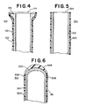
Fig. 4 is a fragmentary, axial cross-sectional view of the open end of a glass safety tube in accordance with a further embodiment of the invention; -
Fig. 5 is a fragmentary, axial cross-sectional view of the open end of a glass safety tube in accordance with an additional embodiment of the invention; -
Fig. 6 is a fragmentary, axial cross-sectional view of the closed end of a glass safety tube in accordance with yet a further embodiment of the invention; -
Fig. 7 is a fragmentary, axial cross-sectional view of the closed end of a glass safety tube in accordance with another embodiment of the invention; and, -
Fig. 8 is an axial, cross-sectional view of a glass safety tube in accordance with another embodiment of the invention. - For the purpose of illustration, there is shown in the accompanying drawings several embodiments of the invention. However, it should be understood by those of ordinary skill in the art that the invention is not limited to the precise arrangements and instrumentalities shown therein and described below. To more clearly illustrate the invention, the drawings are not to scale.
- A glass safety tube in accordance with an embodiment of the invention is shown in
Figs. 1-3 and is designated generally byreference numeral 10. Additional embodiments of the invention are illustrated inFigs. 4-6 . Although the invention is described below as a glass safety tube, it should be appreciated by those of ordinary skill in the art that the invention includes other forms of glass safety tubes, such as a safety glass vacuum tube, having one open end and one closed end. - The
glass safety tube 10 comprises a glass test tube, designated generally byreference numeral 12, having anopen end 14, an elongate, tubularcentral portion 18, and a generally-bulbous, closedend portion 20 integrally formed with thecentral portion 18. Theopen end 14 may also include an integrally-formed, radially-projectinglip 16, which is formed by fire polishing. Referring toFig. 1 , theglass tube 12 has an overall length L1. The central portion has a diameter D and a length L2. The closed end of the tube also has a diameter D and expends axially a distance L3 from thecentral portion 18 as measured from an interface point P show inFig. 2 . For example, the glass tube may comprise a standard vacuum tube, such as made by Chase Scientific, having the dimensions: L1= 11.9 cm; L2=11.8 cm; L3=0.1 cm; and D=0.8 cm. However, it should be understood that a wide variety of different size glass test tubes may be provided without departing from the scope of the present invention. - A first safety barrier envelops the
central portion 18 of theglass tube 12. In the embodiment shown inFigs. 1-3 , the first safety barrier comprises tear-resistant, polymer sheeting, designated generally bereference numeral 22, wrapped around and adhered to thecentral portion 18 of theglass tube 12. Preferably, thesheeting 22 comprises a heat sealable polyester film that is adhered to thecentral portion 18. - For best results, the
sheeting 22 comprises 1.5 mil, oven-lidding Mylar® sold by Dupont Teijin Films. The Mylar® sheeting has an inner adhesive layer and is typically supplied as a non-tacky film sheet with no peelable backing layer. The adhesive becomes tacky at about 200°F and has excellent adhesive properties. - Referring to
Fig. 3 , thesheeting 22 is wrapped several times around thecentral portion 18 beginning with the firstradial end 32 adhered to theglass tube 12 and terminating with the second radial end 34 overlaying and adhering to thesheeting 22 itself. The number of times thesheeting 22 is wrapped around theglass tube 12 will depend on the thickness and type ofsheeting 22. For example, acceptable results are achieved by wrapping 1.5 mil Mylar® 3 to 4 times around theglass tube 12. Thesheeting 22 is wrapped around thecentral portion 18 of theglass tube 12 so that the adhesive side of the inner layer of sheeting contacts and adheres to the outer surface of thecentral portion 18. Preferably, at least one additional layer ofsheeting 22 is then wrapped over and adhered to the outer surface of the inner layer ofsheeting 22. - In the preferred embodiment, the
sheeting 22 is adhered to theglass tube 12 by an adhesive that is provided as a layer on thesheeting 22. However, it is within the scope of the present invention to adhere non-adhesive sheeting to the glass tube by first applying a separate adhesive and then applying the non-adhesive sheeting. - The
sheeting 22 is preferably clear so that the user can observe the contents of theglass tube 12. If thesheeting 22 is wrinkled or otherwise not laid flay over itself, clarity will be obstructed. To prevent wrinkling, the sheeting preferably does not overlay the radial lip. Instead, the firstaxial end 24 of thesheeting 22 is applied immediately adjacent theradial lip 16 of theglass tube 12 as best seen inFig. 1 . - Referring to
Figs. 1 and 2 , the axial length LB of the sheeting is selected so that aportion 30 of the sheeting extends axially a short distance past the interface of thecentral portion 18 and theclosed end portion 20, designated by reference letter P. It should be appreciated that the interface P is merely a point of reference and not a physical boundary since theclosed end portion 20 andcentral portion 18 are integrally formed. The interface P is designated as the axial location at which the bulbous outer surface of theclosed end portion 20 intersects the tubularcentral portion 18. - As best seen in
Fig. 2 , theextension portion 30 does not contact theclosed end portion 20, but rather extends axially parallel to the walls of thecentral portion 18. Theextension portion 30 forms an annular reservoir surrounding theclosed end portion 20 of theglass tube 12. In a preferred embodiment, theextension portion 30 extends at least about 2 mm past the interface P. - A second safety barrier adheres to and envelops the
closed end portion 20 of theglass tube 12. In the embodiment shown inFigs. 1-3 , the second safety barrier comprises acurable adhesive 28, which adheres to theclosed end portion 20 and theextension portion 30. For ease of production, the adhesive 28 is preferably a quick-cure type such as hot melt adhesive, quick-set epoxy, or UV-cured adhesive. For example, the adhesive may comprise Loctite® 236 hot melt, Loctite® U-09LV urethane, Loctite E-OSCL epoxy, or Loctite® 3107 UV. Each of the aforementioned adhesives provides acceptable properties. While hot melt adhesive is the least expensive of the aforementioned materials, UV cured adhesive provides the best clarity. - Referring to
Fig. 2 , the second barrier is created by depositing a controlled amount of adhesive 28 on theclosed end 20 of theglass tube 12. The adhesive 28 collects within the reservoir formed by theextension portion 30 of thesheeting 20. Upon curing, the adhesive adheres to both theclosed end 20 of theglass tube 12 and theextension portion 30 of thesheeting 20. The shape of thesecond safety barrier 22 may be affected by the viscosity of the adhesive and the length of theextension portion 30. - In a preferred embodiment shown in
Fig. 2 , the axial length LB of thesheeting 22 is less than the length L1 of the glass tube and the length of theextension portion 30 is less than or about equal to the length L3 of theclosed end portion 20. In this embodiment, the adhesive 28 forms a flush interface and connection with the secondaxial end 26 of thesheeting 22. - In the embodiment shown in
Figs. 1-3 , thesheeting 22 contains identifyingindicia 36 imprinted thereon, which is visible to the user. In the preferred embodiment, clear sheeting is used as the first safety barrier. The identifyingindicia 36 can then be imprinted on the portion of thesheeting 22 that forms one of the intermediate layers of the first safety barrier, thereby protecting the identifyingindicia 36 from removal, alteration or obstruction. - The
sheeting 22 and adhesive 28 generally increase the strength of theglass tube 12 to prevent breakage. Further, thesheeting 22 and adhesive 28 form a very durable encapsulating safety barrier than contains the glass tube and its contents if the glass tube is fractured or broken. Under normal circumstances, the safety barrier remains intact and protects the user from injury or contamination if the glass tube is fractured or broken. - In a preferred embodiment, the
safety tube 10 is made by initially providing aglass tube 12 as described above. Theglass tube 12 is heated to about 200 - 275 °F. Thecentral portion 18 of the tube is then wrapped with the tear-resistant polymer sheeting. 22. The secondaxial end 26 of thesheeting 22 is extended past the interface P of thecentral portion 18 and theclosed end portion 20, thereby forming an annular reservoir surrounding theclosed end portion 20. During wrapping, theglass tube 12 may be oriented vertically or horizontally. - After the
glass tube 12 is wrapped, it is oriented vertically with theclosed end portion 20 oriented upwardly. The second safety barrier is then formed by depositing a predetermined amount of adhesive 28 on theclosed end portion 20 of the glass tube and allowing the adhesive 28 to cure. If hot melt glue is selected as the second safety barrier, the glue should be applied in a circular pattern around the periphery of the reservoir to prevent formation of air pockets in the deepest channels of the reservoir. If epoxy or UV cured adhesives are selected as the second safety barrier, the adhesive may be centrally deposited at the apex of theclosed end portion 20. Depending on the adhesive, the curing process may be accelerated by heating. - In a preferred embodiment, the length of the
extension portion 30 of thesheeting 22 is less than or about equal to the length L3 of theclosed end portion 20. In this embodiment, the amount of adhesive 28 deposited on theglass tube 12 is controlled so that the adhesive does not overflow the reservoir but forms a flush interface with the firstaxial end 24 of thesheeting 22. - A glass safety tube in accordance with a further embodiment of the invention is shown in
Fig. 4 and is designated generally by reference numeral 110. The safety tube 110 comprises aglass test tube 112 identical in construction to theglass test tube 12 described above. The safety tube 110 has a construction similar to the safety tube described above. However, in this embodiment, the tear-resistant,polymer sheeting 122 extends over and envelops theopen end 114 of theglass tube 112, including the integrally-formed, radially-projectinglip 116. - A glass safety tube in accordance with an additional embodiment of the invention is shown in
Fig. 5 and is designated generally byreference numeral 210. Thesafety tube 210 comprises aglass test tube 212, similar in construction to theglass test tube 12 described above, but lacking the integrally-formed, radially-projectinglip 16. Thesafety tube 210 has a construction similar to thesafety tube 12 described above. However, in this embodiment, the tear-resistant,polymer sheeting 122 extends over and envelops the entire length of the central portion, including theopen end 214 of theglass tube 212. - A glass safety tube in accordance with yet another embodiment of the invention is shown in
Fig. 6 and is designated generally byreference numeral 310. Thesafety tube 310 comprises aglass test tube 312 identical in construction to theglass test tube 12 described above. Thesafety tube 310 has a construction similar to thesafety tube 10 described above. However, in this embodiment, the tear-resistant,polymer sheeting 322 does not extends past the interface of thecentral portion 318 and theclosed end portion 320. In this embodiment, the adhesive 328 of the second safety barrier adheres to theclosed end portion 320 and the secondaxial end 326 of thesheeting 322. - A glass safety tube in accordance with yet another embodiment of the invention is shown in
Fig. 7 and is designated generally byreference numeral 410. Thesafety tube 410 comprises aglass test tube 412 identical in construction to theglass test tube 12 described above. - The
safety tube 410 has a construction similar to thesafety tube 10 described above. However, in this less expensive embodiment, no second barrier layer is provided on theclosed end portion 420 of theglass tube 412 because it is generally the strongest portion of theglass tube 412. Instead, theextension portion 430 of thesheeting 422 extends axially a distance greater than L3 and provides impact protection to theclosed end portion 420. Theextension portion 430 is elastically deformable and acts like shock absorber in the event thesafety tube 410 is dropped or otherwise impacted on theclosed end 430. However, theextension portion 430 does not encapsulate theclosed end portion 430 if it is fractured or broken. While theclosed end portion 420 has no encapsulation or impact protection, thesafety tube 410 it is cheaper to manufacture than the embodiment shown inFigs. 1-3 . - A glass safety tube in accordance with yet another embodiment of the invention is shown in
Fig. 8 and is designated generally byreference numeral 510. Thesafety tube 510 comprises aglass test tube 412 identical in construction to theglass test tube 12 described above. - The
safety tube 510 has a construction similar to thesafety tube 10 described above. However, in this embodiment, no second barrier layer is provided on theclosed end portion 420 of theglass tube 412 because it is generally the strongest portion of theglass tube 412. Further, theprotective sheeting 522 extends only from immediately adjacent theradial lip 516 to the axial interface P of thecentral portion 518 and theclosed end portion 520 of theglass tube 512. While theclosed end portion 520 has no encapsulation or impact protection, thesafety tube 510 is cheaper to manufacture than the embodiment shown inFigs. 1-3 . - The embodiments shown in
Figs. 4-5 are made by the first method described above with respect to the firstglass safety tube 10. The embodiment shown inFig. 6 is made in a manner similar to the first method, except that thesheeting 322 is not extended past the interface P of thecentral portion 18 and theclosed end portion 20, and does not form an annular reservoir surrounding theclosed end portion 20. The embodiment show inFig. 7 is made in a manner similar to the first method, except that the extension portion is longer and no adhesive is applied to theclosed end portion 420 of theglass tube 412. The embodiment shown inFig. 8 is made in a manner similar to the first method, except that except that thesheeting 322 is not extended past the interface P of thecentral portion 18 and theclosed end portion 20, and no adhesive is applied to theclosed end portion 520 of theglass tube 512. - While the principles of the invention have been described above in connection with specific embodiments, it is to be clearly understood that this description is made only by way of example and not as a limitation on the scope of the invention.
Claims (29)
- A glass safety tube (10), comprising,a) a glass tube (12) havingi) a length L1;ii) an elongate tubular central portion (18) with a diameter D and a length L2, which is less than L1;iii) an open end (14); and,iv) a closed end portion (20) integrally formed with said central portion (18) and axially extending a distance L3 from said central portion (18); and,b) a first safety barrier (22) comprising tear-resistant, polymer sheeting enveloping said central portion (18) of said glass tube (12), characterized in that said first sheeting does not contact said closed end portion (20); and said safety tube (10) further comprisesc) a second safety barrier protecting said closed end portion (20), said second safety barrier comprising either a second different material (28) adhering to said closed end portion (20) or an extension portion (30) of said first material that does not adhere to said closed end portion (20) and extends axially past the interface (P) of said central portion (18) and said closed end portion (20).
- The safety tube (10) as claimed in claim 1, wherein said second safety barrier comprises said extension portion (30) of said first material.
- The safety tube (10) as claimed in claim 1, wherein said second safety barrier comprises said second different material adhering to said closed end.
- The safety tube (10) as claimed in claim 2, wherein said extension portion (30) is elastically deformable.
- The safety tube (10) as claimed in claim 2, wherein said extension portion (30) forms an annular reservoir surrounding said closed end portion (20).
- The safety tube (10) as claimed in any one of claims 2 and 3, wherein said open end (14) has an integrally-formed, radially-projecting lip (16) and said first barrier does not envelop said lip (16).
- The safety tube (10) as claimed in claim 2, including a second material that adheres to said closed end portion (20) and to said extension portion (30).
- The safety tube (10) as claimed in any one of claims 2 and 3, wherein said first safety barrier (22) extends from the axial interface location (P) to at least the axial location immediately adjacent the open end (14) of said glass tube (12).
- The safety tube (10) as claimed in any one of claims 2 and 3, wherein said first safety barrier (22) is transparent.
- The safety tube (10) as claimed in any one of claims 2 and 3, wherein said tear-resistant, polymer sheeting is wrapped around and adhered to said central portion (18).
- The safety tube (10) as claimed in claim 10, wherein said sheeting comprises a heat sealable polyester film.
- The safety tube (10) as claimed in claim 10, wherein said sheeting comprises oven lidding Mylar®.
- The safety tube (10) as claimed in claim 3, wherein said second material (28) comprises a hot melt adhesive.
- The safety tube (10) as claimed in any one of claims 3 and 7, wherein said second material comprises a quick-cure epoxy.
- The safety tube (10) as claimed in any one of claims 3 and 7, wherein said second material comprises a UV cured adhesive.
- The safety tube (10) as claimed in any one of claims 2 and 3, wherein said first safety barrier (22) has an axial length LB that is less than L1.
- The safety tube (10) as claimed in any one of claims 3 and 7, wherein said second material (28) forms a flush interface with the ends of said extension portion (30).
- The safety tube (10) as claimed in claim 10, wherein said sheeting includes identifying indicia (36) imprinted thereon.
- The safety tube (10) as claimed in any one of claims 3 and 7, wherein said first safety barrier and said second material form an encapsulating safety barrier that contains the glass tube and its contents if the glass tube is fractured or broken.
- The safety tube (10) as claimed in claim 10, wherein said sheeting includes an inner layer wrapped around and adhered to said central portion (18) and an outer layer adhered to and overlaying the inner layer.
- A method of making a glass safety tube, comprising the steps of,a) providing a glass tube (12) having:i) a length L1;ii) an tubular central portion (18) with a diameter D and a length L2 that is less than L1;iii) an open end (14); and,iii) a bulbous closed end portion (20) integrally formed with said central portion (18) and axially extending a distance L3 from said central portion (18);b) heating the glass tube (12);c) enveloping the central portion (18) of the glass tube (12) with tear-resistant, polymer sheeting; characterized in that said first sheeting does not contact said closed end portion (20); and further characterized by the step ofd) protecting the closed end portion (20) of said glass tube (12) with a second safety barrier comprising either a second different material (28) adhering to said closed end portion (20) or an extension portion (30) of said first material that does not adhere to said closed end (20) and extends axially past the interface (P) of said central portion (18) and said closed end portion (20).
- The method as claimed in claim 21, wherein said second safety barrier comprises said extension portion (30) of said first material.
- The method as claimed in claim 21, wherein said second safety barrier comprises said second different material (28) adhering to said closed end.
- The method as claimed in claim 22, including the step of adhering a second material (28) to said closed end portion (20).
- The method claimed in any one of claims 22 and 23, wherein the central portion (18) of the glass tube (12) is enveloped by wrapping and adhering the sheeting to the central portion (18).
- The method as claimed in claim 25, wherein the central portion (18) of glass tube (12) is enveloped with a heat sealable polyester film that is adhered to the tubular portion.
- The method as claimed in claim 25, wherein the central portion (18) is enveloped with oven-lidding Mylar®.
- The method as claimed in any one of claims 23 and 24, including the step of forming an annular reservoir surrounding the closed end portion (20).
- The method as claimed in claim 28, wherein the annular reservoir is formed by axially extending the sheeting past the interface of the central portion (18) and the closed end portion (20) without contacting the closed end portion (20).
Applications Claiming Priority (2)
| Application Number | Priority Date | Filing Date | Title |
|---|---|---|---|
| US11/114,624 US20060239866A1 (en) | 2005-04-26 | 2005-04-26 | Glass safety tube |
| PCT/US2006/015493 WO2006116320A2 (en) | 2005-04-26 | 2006-04-20 | Glass safety tube |
Publications (3)
| Publication Number | Publication Date |
|---|---|
| EP1874473A2 EP1874473A2 (en) | 2008-01-09 |
| EP1874473A4 EP1874473A4 (en) | 2010-03-03 |
| EP1874473B1 true EP1874473B1 (en) | 2012-06-20 |
Family
ID=37187121
Family Applications (1)
| Application Number | Title | Priority Date | Filing Date |
|---|---|---|---|
| EP06751267A Expired - Lifetime EP1874473B1 (en) | 2005-04-26 | 2006-04-20 | Glass safety tube |
Country Status (4)
| Country | Link |
|---|---|
| US (1) | US20060239866A1 (en) |
| EP (1) | EP1874473B1 (en) |
| JP (1) | JP2008539074A (en) |
| WO (1) | WO2006116320A2 (en) |
Families Citing this family (7)
| Publication number | Priority date | Publication date | Assignee | Title |
|---|---|---|---|---|
| US7419832B2 (en) * | 2005-03-10 | 2008-09-02 | Streck, Inc. | Blood collection tube with surfactant |
| US7608457B2 (en) * | 2005-03-10 | 2009-10-27 | Streck, Inc. | Blood collection and testing improvements |
| US20140152801A1 (en) | 2009-10-28 | 2014-06-05 | Alentic Microscience Inc. | Detecting and Using Light Representative of a Sample |
| JP2013509618A (en) | 2009-10-28 | 2013-03-14 | アレンティック マイクロサイエンス インコーポレイテッド | Microscopic imaging |
| WO2014205576A1 (en) | 2013-06-26 | 2014-12-31 | Alentic Microscience Inc. | Sample processing improvements for microscopy |
| EP3460482B1 (en) * | 2017-09-25 | 2022-08-31 | Roche Diagnostics GmbH | Method of handling a laboratory sample container, laboratory apparatus and laboratory automation system |
| JP7339710B1 (en) | 2022-10-25 | 2023-09-06 | 北斗制御株式会社 | SOLAR HEAT COLLECTOR AND MANUFACTURING METHOD THEREOF, SOLAR HOT WATER AND SOLAR HEATING DEVICE USING SOLAR HEAT COLLECTOR |
Family Cites Families (8)
| Publication number | Priority date | Publication date | Assignee | Title |
|---|---|---|---|---|
| DE2731635C2 (en) * | 1976-07-16 | 1985-07-25 | Owens-Illinois, Inc., Toledo, Ohio | Bottle made of biaxially oriented polyester |
| JPS56102635U (en) * | 1979-12-28 | 1981-08-12 | ||
| US5019243A (en) * | 1987-04-03 | 1991-05-28 | Mcewen James A | Apparatus for collecting blood |
| US4852584A (en) * | 1988-10-11 | 1989-08-01 | Selby Charles R | Fluid collection tube with a safety funnel at its open end |
| US5545375A (en) * | 1994-10-03 | 1996-08-13 | Becton, Dickinson And Company | Blood collection tube assembly |
| US5975343A (en) * | 1997-09-12 | 1999-11-02 | Becton Dickinson And Company | Collection container assembly |
| US6354452B1 (en) * | 2000-07-25 | 2002-03-12 | Becton, Dickinson And Company | Collection container assembly |
| US6884459B2 (en) * | 2002-06-27 | 2005-04-26 | Orion Industries, Ltd. | Method of manufacturing perfluoroalkoxy copolymer coated glass |
-
2005
- 2005-04-26 US US11/114,624 patent/US20060239866A1/en not_active Abandoned
-
2006
- 2006-04-20 EP EP06751267A patent/EP1874473B1/en not_active Expired - Lifetime
- 2006-04-20 WO PCT/US2006/015493 patent/WO2006116320A2/en not_active Ceased
- 2006-04-20 JP JP2008509011A patent/JP2008539074A/en active Pending
Also Published As
| Publication number | Publication date |
|---|---|
| US20060239866A1 (en) | 2006-10-26 |
| WO2006116320A3 (en) | 2007-11-01 |
| EP1874473A4 (en) | 2010-03-03 |
| WO2006116320A2 (en) | 2006-11-02 |
| EP1874473A2 (en) | 2008-01-09 |
| JP2008539074A (en) | 2008-11-13 |
Similar Documents
| Publication | Publication Date | Title |
|---|---|---|
| CA2048151C (en) | Method of packaging an adhesive composition and corresponding packaged article | |
| EP1797542B1 (en) | Closure for a container, overcap, and method of making it | |
| US5325721A (en) | System for indicating exposure to preselected temperatures or tampering | |
| US20060239866A1 (en) | Glass safety tube | |
| US5979714A (en) | Glass bottle with a sprayed on synthetic coating, its production process and device necessary for its production | |
| EP1026092A1 (en) | Container for moisture-sensitive products | |
| CN204632247U (en) | A clasp-type label for a drug testing reagent bottle | |
| CN103826864B (en) | In-mold transfer film which changes its color according to a temperature and which has a scent-emitting function and method for manufacturing same | |
| KR930017805A (en) | Tamper Evidence Closer | |
| TW201545896A (en) | Thin glass composite and method for storing a thin glass film | |
| EP1754971B1 (en) | Rapid diagnostic strip comprising a moisture-absorbing material and the blister packaging thereof | |
| WO2015146838A1 (en) | Gas-permeable label | |
| HU220885B1 (en) | Tamper evident closure, and process for producing thereof | |
| ES2326977T3 (en) | ADHESIVE SHEET FOR TIRES AND METHOD TO MANUFACTURE THE SAME. | |
| JP2018089800A (en) | Resin sheet and method for producing the same | |
| KR101249551B1 (en) | Adhesive sheet | |
| WO2010107270A2 (en) | Flexible tube sheet, and method for manufacturing a tube body | |
| WO2011049564A1 (en) | Photoinitiated optical adhesive and method for using same | |
| US9186844B2 (en) | Method for forming an edge protection element on a glass article | |
| CN110654713A (en) | Aluminum-plastic cover film for blister packaging and easy to position and cut by cursor and preparation method | |
| JP2000079796A (en) | Laminate film for manufacturing insert molding, manufacture of insert film using the film, and manufacture of insert molding | |
| KR102847782B1 (en) | Labels and their manufacturing methods | |
| JP2005280782A (en) | Large-sized plastic bottle with label | |
| US20100025266A1 (en) | Blistered rapid diagnostic test with incorporated moisture absorbent material | |
| JP2873551B2 (en) | Label and label manufacturing method |
Legal Events
| Date | Code | Title | Description |
|---|---|---|---|
| PUAI | Public reference made under article 153(3) epc to a published international application that has entered the european phase |
Free format text: ORIGINAL CODE: 0009012 |
|
| 17P | Request for examination filed |
Effective date: 20071109 |
|
| AK | Designated contracting states |
Kind code of ref document: A2 Designated state(s): AT BE BG CH CY CZ DE DK EE ES FI FR GB GR HU IE IS IT LI LT LU LV MC NL PL PT RO SE SI SK TR |
|
| AX | Request for extension of the european patent |
Extension state: AL BA HR MK YU |
|
| DAX | Request for extension of the european patent (deleted) | ||
| A4 | Supplementary search report drawn up and despatched |
Effective date: 20100128 |
|
| 17Q | First examination report despatched |
Effective date: 20100614 |
|
| REG | Reference to a national code |
Ref country code: DE Ref legal event code: R079 Ref document number: 602006030330 Country of ref document: DE Free format text: PREVIOUS MAIN CLASS: B01L0009000000 Ipc: B01L0003140000 |
|
| GRAP | Despatch of communication of intention to grant a patent |
Free format text: ORIGINAL CODE: EPIDOSNIGR1 |
|
| RIC1 | Information provided on ipc code assigned before grant |
Ipc: B01L 3/14 20060101AFI20110801BHEP |
|
| GRAS | Grant fee paid |
Free format text: ORIGINAL CODE: EPIDOSNIGR3 |
|
| GRAA | (expected) grant |
Free format text: ORIGINAL CODE: 0009210 |
|
| AK | Designated contracting states |
Kind code of ref document: B1 Designated state(s): AT BE BG CH CY CZ DE DK EE ES FI FR GB GR HU IE IS IT LI LT LU LV MC NL PL PT RO SE SI SK TR |
|
| REG | Reference to a national code |
Ref country code: GB Ref legal event code: FG4D |
|
| REG | Reference to a national code |
Ref country code: CH Ref legal event code: EP |
|
| REG | Reference to a national code |
Ref country code: AT Ref legal event code: REF Ref document number: 562706 Country of ref document: AT Kind code of ref document: T Effective date: 20120715 |
|
| REG | Reference to a national code |
Ref country code: IE Ref legal event code: FG4D |
|
| REG | Reference to a national code |
Ref country code: DE Ref legal event code: R096 Ref document number: 602006030330 Country of ref document: DE Effective date: 20120816 |
|
| PG25 | Lapsed in a contracting state [announced via postgrant information from national office to epo] |
Ref country code: FI Free format text: LAPSE BECAUSE OF FAILURE TO SUBMIT A TRANSLATION OF THE DESCRIPTION OR TO PAY THE FEE WITHIN THE PRESCRIBED TIME-LIMIT Effective date: 20120620 Ref country code: LT Free format text: LAPSE BECAUSE OF FAILURE TO SUBMIT A TRANSLATION OF THE DESCRIPTION OR TO PAY THE FEE WITHIN THE PRESCRIBED TIME-LIMIT Effective date: 20120620 Ref country code: SE Free format text: LAPSE BECAUSE OF FAILURE TO SUBMIT A TRANSLATION OF THE DESCRIPTION OR TO PAY THE FEE WITHIN THE PRESCRIBED TIME-LIMIT Effective date: 20120620 |
|
| REG | Reference to a national code |
Ref country code: NL Ref legal event code: VDEP Effective date: 20120620 |
|
| REG | Reference to a national code |
Ref country code: AT Ref legal event code: MK05 Ref document number: 562706 Country of ref document: AT Kind code of ref document: T Effective date: 20120620 |
|
| REG | Reference to a national code |
Ref country code: LT Ref legal event code: MG4D Effective date: 20120620 |
|
| PG25 | Lapsed in a contracting state [announced via postgrant information from national office to epo] |
Ref country code: GR Free format text: LAPSE BECAUSE OF FAILURE TO SUBMIT A TRANSLATION OF THE DESCRIPTION OR TO PAY THE FEE WITHIN THE PRESCRIBED TIME-LIMIT Effective date: 20120921 Ref country code: LV Free format text: LAPSE BECAUSE OF FAILURE TO SUBMIT A TRANSLATION OF THE DESCRIPTION OR TO PAY THE FEE WITHIN THE PRESCRIBED TIME-LIMIT Effective date: 20120620 Ref country code: SI Free format text: LAPSE BECAUSE OF FAILURE TO SUBMIT A TRANSLATION OF THE DESCRIPTION OR TO PAY THE FEE WITHIN THE PRESCRIBED TIME-LIMIT Effective date: 20120620 |
|
| PG25 | Lapsed in a contracting state [announced via postgrant information from national office to epo] |
Ref country code: BE Free format text: LAPSE BECAUSE OF FAILURE TO SUBMIT A TRANSLATION OF THE DESCRIPTION OR TO PAY THE FEE WITHIN THE PRESCRIBED TIME-LIMIT Effective date: 20120620 Ref country code: IS Free format text: LAPSE BECAUSE OF FAILURE TO SUBMIT A TRANSLATION OF THE DESCRIPTION OR TO PAY THE FEE WITHIN THE PRESCRIBED TIME-LIMIT Effective date: 20121020 Ref country code: AT Free format text: LAPSE BECAUSE OF FAILURE TO SUBMIT A TRANSLATION OF THE DESCRIPTION OR TO PAY THE FEE WITHIN THE PRESCRIBED TIME-LIMIT Effective date: 20120620 Ref country code: EE Free format text: LAPSE BECAUSE OF FAILURE TO SUBMIT A TRANSLATION OF THE DESCRIPTION OR TO PAY THE FEE WITHIN THE PRESCRIBED TIME-LIMIT Effective date: 20120620 Ref country code: SK Free format text: LAPSE BECAUSE OF FAILURE TO SUBMIT A TRANSLATION OF THE DESCRIPTION OR TO PAY THE FEE WITHIN THE PRESCRIBED TIME-LIMIT Effective date: 20120620 Ref country code: CZ Free format text: LAPSE BECAUSE OF FAILURE TO SUBMIT A TRANSLATION OF THE DESCRIPTION OR TO PAY THE FEE WITHIN THE PRESCRIBED TIME-LIMIT Effective date: 20120620 Ref country code: RO Free format text: LAPSE BECAUSE OF FAILURE TO SUBMIT A TRANSLATION OF THE DESCRIPTION OR TO PAY THE FEE WITHIN THE PRESCRIBED TIME-LIMIT Effective date: 20120620 Ref country code: CY Free format text: LAPSE BECAUSE OF FAILURE TO SUBMIT A TRANSLATION OF THE DESCRIPTION OR TO PAY THE FEE WITHIN THE PRESCRIBED TIME-LIMIT Effective date: 20120620 |
|
| PG25 | Lapsed in a contracting state [announced via postgrant information from national office to epo] |
Ref country code: PT Free format text: LAPSE BECAUSE OF FAILURE TO SUBMIT A TRANSLATION OF THE DESCRIPTION OR TO PAY THE FEE WITHIN THE PRESCRIBED TIME-LIMIT Effective date: 20121022 Ref country code: IT Free format text: LAPSE BECAUSE OF FAILURE TO SUBMIT A TRANSLATION OF THE DESCRIPTION OR TO PAY THE FEE WITHIN THE PRESCRIBED TIME-LIMIT Effective date: 20120620 Ref country code: PL Free format text: LAPSE BECAUSE OF FAILURE TO SUBMIT A TRANSLATION OF THE DESCRIPTION OR TO PAY THE FEE WITHIN THE PRESCRIBED TIME-LIMIT Effective date: 20120620 |
|
| PG25 | Lapsed in a contracting state [announced via postgrant information from national office to epo] |
Ref country code: NL Free format text: LAPSE BECAUSE OF FAILURE TO SUBMIT A TRANSLATION OF THE DESCRIPTION OR TO PAY THE FEE WITHIN THE PRESCRIBED TIME-LIMIT Effective date: 20120620 |
|
| PLBE | No opposition filed within time limit |
Free format text: ORIGINAL CODE: 0009261 |
|
| STAA | Information on the status of an ep patent application or granted ep patent |
Free format text: STATUS: NO OPPOSITION FILED WITHIN TIME LIMIT |
|
| PG25 | Lapsed in a contracting state [announced via postgrant information from national office to epo] |
Ref country code: ES Free format text: LAPSE BECAUSE OF FAILURE TO SUBMIT A TRANSLATION OF THE DESCRIPTION OR TO PAY THE FEE WITHIN THE PRESCRIBED TIME-LIMIT Effective date: 20121001 Ref country code: DK Free format text: LAPSE BECAUSE OF FAILURE TO SUBMIT A TRANSLATION OF THE DESCRIPTION OR TO PAY THE FEE WITHIN THE PRESCRIBED TIME-LIMIT Effective date: 20120620 |
|
| 26N | No opposition filed |
Effective date: 20130321 |
|
| REG | Reference to a national code |
Ref country code: DE Ref legal event code: R097 Ref document number: 602006030330 Country of ref document: DE Effective date: 20130321 |
|
| PG25 | Lapsed in a contracting state [announced via postgrant information from national office to epo] |
Ref country code: BG Free format text: LAPSE BECAUSE OF FAILURE TO SUBMIT A TRANSLATION OF THE DESCRIPTION OR TO PAY THE FEE WITHIN THE PRESCRIBED TIME-LIMIT Effective date: 20120920 |
|
| PG25 | Lapsed in a contracting state [announced via postgrant information from national office to epo] |
Ref country code: MC Free format text: LAPSE BECAUSE OF FAILURE TO SUBMIT A TRANSLATION OF THE DESCRIPTION OR TO PAY THE FEE WITHIN THE PRESCRIBED TIME-LIMIT Effective date: 20120620 |
|
| REG | Reference to a national code |
Ref country code: CH Ref legal event code: PL |
|
| GBPC | Gb: european patent ceased through non-payment of renewal fee |
Effective date: 20130420 |
|
| REG | Reference to a national code |
Ref country code: IE Ref legal event code: MM4A |
|
| PG25 | Lapsed in a contracting state [announced via postgrant information from national office to epo] |
Ref country code: DE Free format text: LAPSE BECAUSE OF NON-PAYMENT OF DUE FEES Effective date: 20131101 Ref country code: LI Free format text: LAPSE BECAUSE OF NON-PAYMENT OF DUE FEES Effective date: 20130430 Ref country code: GB Free format text: LAPSE BECAUSE OF NON-PAYMENT OF DUE FEES Effective date: 20130420 Ref country code: CH Free format text: LAPSE BECAUSE OF NON-PAYMENT OF DUE FEES Effective date: 20130430 |
|
| REG | Reference to a national code |
Ref country code: FR Ref legal event code: ST Effective date: 20131231 |
|
| REG | Reference to a national code |
Ref country code: DE Ref legal event code: R119 Ref document number: 602006030330 Country of ref document: DE Effective date: 20131101 |
|
| PG25 | Lapsed in a contracting state [announced via postgrant information from national office to epo] |
Ref country code: FR Free format text: LAPSE BECAUSE OF NON-PAYMENT OF DUE FEES Effective date: 20130430 |
|
| PG25 | Lapsed in a contracting state [announced via postgrant information from national office to epo] |
Ref country code: IE Free format text: LAPSE BECAUSE OF NON-PAYMENT OF DUE FEES Effective date: 20130420 |
|
| PG25 | Lapsed in a contracting state [announced via postgrant information from national office to epo] |
Ref country code: TR Free format text: LAPSE BECAUSE OF FAILURE TO SUBMIT A TRANSLATION OF THE DESCRIPTION OR TO PAY THE FEE WITHIN THE PRESCRIBED TIME-LIMIT Effective date: 20120620 |
|
| PG25 | Lapsed in a contracting state [announced via postgrant information from national office to epo] |
Ref country code: LU Free format text: LAPSE BECAUSE OF NON-PAYMENT OF DUE FEES Effective date: 20130420 Ref country code: HU Free format text: LAPSE BECAUSE OF FAILURE TO SUBMIT A TRANSLATION OF THE DESCRIPTION OR TO PAY THE FEE WITHIN THE PRESCRIBED TIME-LIMIT; INVALID AB INITIO Effective date: 20060420 |