EP1873500A1 - Fill level sensor device for a storage container with an outlet for storing an electrically conductible fluid for a domestic appliance - Google Patents
Fill level sensor device for a storage container with an outlet for storing an electrically conductible fluid for a domestic appliance Download PDFInfo
- Publication number
- EP1873500A1 EP1873500A1 EP07010943A EP07010943A EP1873500A1 EP 1873500 A1 EP1873500 A1 EP 1873500A1 EP 07010943 A EP07010943 A EP 07010943A EP 07010943 A EP07010943 A EP 07010943A EP 1873500 A1 EP1873500 A1 EP 1873500A1
- Authority
- EP
- European Patent Office
- Prior art keywords
- sensor device
- electrode
- level sensor
- reservoir
- electrical
- Prior art date
- Legal status (The legal status is an assumption and is not a legal conclusion. Google has not performed a legal analysis and makes no representation as to the accuracy of the status listed.)
- Granted
Links
Images

Classifications
-
- G—PHYSICS
- G01—MEASURING; TESTING
- G01F—MEASURING VOLUME, VOLUME FLOW, MASS FLOW OR LIQUID LEVEL; METERING BY VOLUME
- G01F23/00—Indicating or measuring liquid level or level of fluent solid material, e.g. indicating in terms of volume or indicating by means of an alarm
- G01F23/22—Indicating or measuring liquid level or level of fluent solid material, e.g. indicating in terms of volume or indicating by means of an alarm by measuring physical variables, other than linear dimensions, pressure or weight, dependent on the level to be measured, e.g. by difference of heat transfer of steam or water
- G01F23/26—Indicating or measuring liquid level or level of fluent solid material, e.g. indicating in terms of volume or indicating by means of an alarm by measuring physical variables, other than linear dimensions, pressure or weight, dependent on the level to be measured, e.g. by difference of heat transfer of steam or water by measuring variations of capacity or inductance of capacitors or inductors arising from the presence of liquid or fluent solid material in the electric or electromagnetic fields
- G01F23/263—Indicating or measuring liquid level or level of fluent solid material, e.g. indicating in terms of volume or indicating by means of an alarm by measuring physical variables, other than linear dimensions, pressure or weight, dependent on the level to be measured, e.g. by difference of heat transfer of steam or water by measuring variations of capacity or inductance of capacitors or inductors arising from the presence of liquid or fluent solid material in the electric or electromagnetic fields by measuring variations in capacitance of capacitors
- G01F23/266—Indicating or measuring liquid level or level of fluent solid material, e.g. indicating in terms of volume or indicating by means of an alarm by measuring physical variables, other than linear dimensions, pressure or weight, dependent on the level to be measured, e.g. by difference of heat transfer of steam or water by measuring variations of capacity or inductance of capacitors or inductors arising from the presence of liquid or fluent solid material in the electric or electromagnetic fields by measuring variations in capacitance of capacitors measuring circuits therefor
-
- A—HUMAN NECESSITIES
- A47—FURNITURE; DOMESTIC ARTICLES OR APPLIANCES; COFFEE MILLS; SPICE MILLS; SUCTION CLEANERS IN GENERAL
- A47J—KITCHEN EQUIPMENT; COFFEE MILLS; SPICE MILLS; APPARATUS FOR MAKING BEVERAGES
- A47J31/00—Apparatus for making beverages
- A47J31/44—Parts or details or accessories of beverage-making apparatus
- A47J31/4403—Constructional details
-
- A—HUMAN NECESSITIES
- A47—FURNITURE; DOMESTIC ARTICLES OR APPLIANCES; COFFEE MILLS; SPICE MILLS; SUCTION CLEANERS IN GENERAL
- A47J—KITCHEN EQUIPMENT; COFFEE MILLS; SPICE MILLS; APPARATUS FOR MAKING BEVERAGES
- A47J2203/00—Devices having filling level indicating means
-
- A—HUMAN NECESSITIES
- A47—FURNITURE; DOMESTIC ARTICLES OR APPLIANCES; COFFEE MILLS; SPICE MILLS; SUCTION CLEANERS IN GENERAL
- A47J—KITCHEN EQUIPMENT; COFFEE MILLS; SPICE MILLS; APPARATUS FOR MAKING BEVERAGES
- A47J31/00—Apparatus for making beverages
- A47J31/44—Parts or details or accessories of beverage-making apparatus
- A47J31/4403—Constructional details
- A47J31/4457—Water-level indicators
Definitions
- the invention relates to a filling level sensor device for a storage container with an outlet for storing an electrically conductive fluid of a household appliance according to the type mentioned in the preamble of claim 1.
- Such a level sensor device is for example already out of the DE 35 41 752 A1 known.
- the known filling level sensor device includes an electrical control having an evaluation circuit, a memory and a power supply.
- the reservoir is made of an electrically conductive material, wherein in the storage space a current-transmitting connected to the electrical power supply and electrically isolated from the reservoir electrode is at least partially disposed.
- the strength of the current flow or a physical variable corresponding thereto in the evaluation circuit is comparable to a reference value stored in the memory. For this it is necessary that the reservoir is electrically grounded.
- the invention thus provides the problem of providing a level sensor device that can be realized with less design effort.
- the achievable with the present invention consist in particular in a lower design effort in the realization of a level sensor device and thus a more cost-effective production.
- the level sensor device according to the invention it is possible to monitor a single level, for example a minimum level, so to recognize.
- a multiple arrangement of the level sensor device according to the invention would be required.
- a galvanic connection between the reservoir and ground is not required.
- this makes it possible to make the arrangement of the reservoir and thus the level sensor device free, so that the space available on or in the household appliance space can be used to save space.
- the electrode is formed as part of an inlet or as part of the outlet of the reservoir. That way is the Level sensor device further simplifies construction and even more cost-effective.
- a particularly advantageous embodiment provides that the reservoir is formed removably from the housing of the household appliance and the current-transmitting connection between the electrical power supply and the electrode by the transfer of the reservoir in its operating position, in which the reservoir is at least fluidly connected to the outlet, is automatically produced. This improves user comfort.
- the current-transmitting connection is formed in the operating position of the reservoir as a galvanic connection, which can be produced via corresponding electrical contact surfaces of the electrode and the electrical control.
- the aforementioned embodiment is realized in a particularly simple manner.
- the formation of the contact surfaces of the aforementioned galvanic connection can be selected within wide suitable limits.
- the electrical contact surface associated with the electrical control has at least one elevation and is biased by means of a spring element such that the elevation during the transfer of the reservoir into the operating position partially penetrates into the electrical contact surface associated with the electrode.
- a reliable galvanic contacting of the two contact surfaces is guaranteed even under difficult environmental conditions.
- at least one of the two contact surfaces deposits or forms an electrically insulating coating over time. This coating would then be penetrated in a renewed transfer of the reservoir in its operating position of the survey, so that the galvanic contact between the two contact surfaces is made in this way.
- a filling level sensor device according to the invention with a removable from the household appliance reservoir provides that the current-transmitting connection via a coupling capacitor can be produced, wherein a plate of the coupling capacitor with the electrical control and the other plate of the coupling capacitor is electrically connected to the electrode.
- the embodiment of a filling level sensor device with a reservoir which can be removed from the household appliance can be realized in a structurally particularly simple manner.
- a particularly advantageous development of the aforementioned embodiment provides that the dielectric strength of the coupling capacitor is chosen so high that the use of electrical safety extra-low voltage in the electrical control not is required. For a galvanic connection, it is always necessary for safety reasons that safety extra-low voltage is used in the electrical control. If the dielectric strength of the coupling capacitor is chosen to be sufficiently high, this is no longer necessary. The result is a further simplification of the arrangement and cost reduction.
- the means of structurally influencing the dielectric strength of the coupling capacitor in the desired manner are well known to the person skilled in the art.
- a formed as a beverage maker household appliance 2 is shown schematically with a level sensor device according to the invention.
- the level sensor device has an electrical control 4 with an evaluation circuit 6, a memory 8 and an electrical power supply 10, wherein the electrical power supply 10 generates an alternating voltage and thus an alternating current.
- the level sensor device includes a reservoir 12 for milk made of stainless steel.
- the reservoir 12 is made of another electrically conductive material, such as aluminum, or on its side facing the reservoir 14 side of the container wall carries an electrically conductive coating.
- the filling level sensor device has a partially projecting into the reservoir 14 and electrically insulated from the reservoir 12 electrode 16 which is connected in the operating state of the level sensor device to the electrical power supply 10 to transmit power.
- the storage container 12 of the present embodiment has two outlets 18 configured as milk lines, through which the milk stored in the storage container 12 can be conducted to the milk removal points of the beverage maker 2 (not shown).
- the storage container 12 can be filled with milk via an inlet 20 designed as an opening.
- the reservoir 12 which is held in the operating state of the level sensor device in the interior of the beverage maker 2, removably formed from the beverage maker 2, which will be explained in more detail below.
- the inlet 20 is likewise designed as a milk line, a combination of the electrode 16 with the inlet 20 that would be analogous to this would also be conceivable.
- the removable from the beverage maker 2 reservoir 12 is connected in its operating position in which the reservoir 12 is fluidly connected to the outlets 18, electrically connected by means of a galvanic connection with the electrical power supply 10 of the electric control 4.
- a first electrical contact surface 22 with the electrical control 4 and a second contact surface 24 with the electrode 16 in current transmission connection.
- the first contact surface 22 has a multiplicity of small elevations 26 which ensure the electrical contact between the two contact surfaces 22, 24.
- the contact surface 22 is biased in a manner known to the skilled person by means of a spring element 28 in the direction of the image plane upwards against a arranged on the housing of the beverage maker 2 holder 29.
- the end face of the electrode 16 formed as contact surface 24 grinds over the elevations 26 of the contact surface 22, causing them to penetrate into the surface of the contact surface 24 due to the bias.
- This design of the contact surfaces 22, 24 a secure electrical contact is guaranteed even with potentially passivated surfaces.
- the electrode 16 forms with the reservoir 12 at a level of milk below the level to be sensed, ie below the electrode 16, an electric capacitor 30 with the capacitance c1 and the reservoir 12 with a grounded other household appliance part 31 of the beverage maker 2, an electric capacitor 32 with the capacitance c2, wherein both capacitors 30, 32 are electrically connected in series. Due to the naturally much smaller surface of the electrode 16 compared to the surface of the reservoir 12, the capacitance c1 is much smaller than the capacitance c2.
- the electrical control 4 forms an electrical capacitor 34 with the capacitance c3 via the ambient air with the other household appliance part 31 of the beverage maker 2 which is grounded.
- the electrical control 4 and in particular the reservoir 12 are held in the operating state of the level sensor device floating on the beverage maker 2. Potential-free means that there is no galvanic connection to ground, but the electrical connection to ground takes place solely via the ambient air.
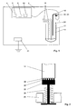
- the reservoir 12 is located in the operating position in the interior of the beverage maker 2. Since the level of stored in the reservoir 14 milk, as shown in FIG. 1, below the electrode 16, form the electrode 16, the reservoir 12 and the electric Control 4, the above explained with reference to FIG. 3 electrical circuit.
- the alternating current between the electrical power supply 10 and the electrode 16 generated by the electrical power supply 10 can be measured and evaluated by the evaluation circuit 6 in a manner known to those skilled in the art, for example by means of an electrical voltage measurement on a resistor connected in parallel and not shown in detail. The measured electrical voltage is compared in the evaluation circuit 6 with a reference value stored in the memory 8.
- the notification to the user the reservoir 12 is filled with milk, due to the constructive training at a time when the outlets 18 still milk can be sucked.
- This is achieved in that the outlets 18 reach deeper into the reservoir 12 than the electrode 16. In this way it is ensured that no air is sucked in through the outlets 18 and thus conveyed.
- an extension piece of electrically non-conductive Material for example, a plastic hose, yogastecken.
- the aforementioned effect is achieved in a structurally simple manner.
- the skilled person for this other suitable alternatives are available.
- the user opens a service door, not shown, of the beverage maker 2 and removes the reservoir 12 for the purpose of filling with milk. After the filling process, the user transfers the reservoir 12 back into the operating position explained above. In this case, a galvanic connection between the two contact surfaces 22, 24 is made, so that again an alternating current between the electric power supply 10 and electrode 16 can flow. Since the level of the milk in the reservoir 12 is above the lower end of the electrode 16, the capacitor 30 is bridged. This is symbolized in FIG. 3 by a switch 35. At a level above the lower end of the electrode 16, the switch 35 of FIG. 3 in the closed position, not shown.
- the capacitors 30, 32 only the capacitor 32 is capacitively effective, which leads to a reduction of the capacitive resistance and thus an increase in the current flowing between the electric power supply 10 and the electrode 16 alternating current.
- the measured electrical voltage is now greater than the stored reference value and the display of the above message disappears automatically.
- a second embodiment of the filling level sensor device according to the invention is shown, in which instead of the galvanic connection via the contact surfaces 22, 24 in the operating position of the removable reservoir 12, the electrode 16 by means of a Coupling capacitor 36 is connected to the power supply 10 to transmit electricity.
- a plate of the coupling capacitor 36 with the electrical power supply 10 and the other plate with the electrode 16 is electrically connected.
- the fill level sensor device according to the invention in embodiments with removable reservoirs 12 structurally even easier to implement.
- electrically insulating deposits and layers on the plates of the coupling capacitor 36 would not interfere with the level sensing.
- this second embodiment furthermore has the advantage that mains voltage can also be used in the electrical control 4; Safety extra-low voltage is then not mandatory.
- the filling level sensor device according to the invention is not limited to the illustrated embodiment. In addition to the sensing of milk, the sensing of other, electrically conductive fluids is possible. Furthermore, the filling level sensor device can also be used in storage containers which are firmly integrated on or in the domestic appliance. The higher frequency the alternating current flowing between the electric power supply 10 and the electrode 16 is selected, the more the electrode 16 acts, in the case that the level is lower than the lower end of the electrode 16, or the reservoir 12, in the event the level is higher than the lower end of the electrode 16, like a transmitting antenna.
Abstract
Description
Die Erfindung betrifft ein Füllstandssensoreinrichtung für einen Vorratsbehälter mit einem Auslauf zur Bevorratung eines elektrisch leitfähigen Fluids eines Haushaltsgeräts nach der im Oberbegriff des Anspruchs 1 genannten Art.The invention relates to a filling level sensor device for a storage container with an outlet for storing an electrically conductive fluid of a household appliance according to the type mentioned in the preamble of claim 1.
Eine derartige Füllstandssensoreinrichtung ist beispielsweise bereits aus der
Der Erfindung stellt sich somit das Problem eine Füllstandssensoreinrichtung anzugeben, die mit geringerem konstruktiven Aufwand realisierbar ist.The invention thus provides the problem of providing a level sensor device that can be realized with less design effort.
Erfindungsgemäß wird dieses Problem durch eine Füllstandssensoreinrichtung mit den Merkmalen des Patentanspruchs 1 gelöst. Vorteilhafte Ausgestaltungen und Weiterbildungen der Erfindung ergeben sich aus den nachfolgenden Unteransprüchen.According to the invention, this problem is solved by a filling level sensor device having the features of patent claim 1. Advantageous embodiments and further developments of the invention will become apparent from the following subclaims.
Die mit der Erfindung erreichbaren Vorteile bestehen insbesondere in einem geringeren konstruktiven Aufwand bei der Realisierung einer Füllstandssensoreinrichtung und damit einer kostengünstigeren Herstellung. Mit der erfindungsgemäßen Füllstandssensoreinrichtung ist es möglich, einen einzigen Füllstand, beispielsweise einen Mindestfüllstand, zu überwachen, also zu erkennen. Für die Überwachung mehrerer voneinander verschiedener Füllstände wäre eine Mehrfachanordnung der erfindungsgemäßen Füllstandssensoreinrichtung erforderlich. Eine galvanische Verbindung zwischen dem Vorratsbehälter und Masse ist nicht erforderlich. Darüber hinaus ist es hierdurch möglich, die Anordnung des Vorratsbehälters und damit der Füllstandssensoreinrichtung freier zu gestalten, so dass der an oder in dem Haushaltsgerät zur Verfügung stehende Bauraum platzsparender genutzt werden kann.The achievable with the present invention consist in particular in a lower design effort in the realization of a level sensor device and thus a more cost-effective production. With the level sensor device according to the invention, it is possible to monitor a single level, for example a minimum level, so to recognize. For the monitoring of several mutually different levels, a multiple arrangement of the level sensor device according to the invention would be required. A galvanic connection between the reservoir and ground is not required. Moreover, this makes it possible to make the arrangement of the reservoir and thus the level sensor device free, so that the space available on or in the household appliance space can be used to save space.
Eine vorteilhafte Weiterbildung sieht vor, dass die Elektrode als ein Teil eines Zulaufs oder als ein Teil des Auslaufs des Vorratsbehälters ausgebildet ist. Auf diese Weise ist die Füllstandssensoreinrichtung konstruktiv weiter vereinfacht und noch kostengünstiger realisierbar.An advantageous development provides that the electrode is formed as part of an inlet or as part of the outlet of the reservoir. That way is the Level sensor device further simplifies construction and even more cost-effective.
Eine besonders vorteilhafte Weiterbildung sieht vor, dass der Vorratsbehälter von dem Gehäuse des Haushaltsgeräts entnehmbar ausgebildet ist und die stromübertragende Verbindung zwischen der elektrischen Stromversorgung und der Elektrode durch die Überführung des Vorratsbehälters in dessen Betriebslage, in der der Vorratsbehälter zumindest mit dem Auslauf fluidleitend verbunden ist, automatisch herstellbar ist. Hierdurch ist der Benutzerkomfort verbessert.A particularly advantageous embodiment provides that the reservoir is formed removably from the housing of the household appliance and the current-transmitting connection between the electrical power supply and the electrode by the transfer of the reservoir in its operating position, in which the reservoir is at least fluidly connected to the outlet, is automatically produced. This improves user comfort.
Eine vorteilhafte Weiterbildung der vorgenannten Ausführungsform sieht vor, dass die stromübertragende Verbindung in der Betriebslage des Vorratsbehälters als eine galvanische Verbindung ausgebildet ist, wobei diese über korrespondierende elektrische Kontaktflächen der Elektrode und der elektrischen Steuerung herstellbar ist. Hierdurch ist die vorgenannte Ausführungsform auf besonders einfache Weise realisiert.An advantageous development of the aforementioned embodiment provides that the current-transmitting connection is formed in the operating position of the reservoir as a galvanic connection, which can be produced via corresponding electrical contact surfaces of the electrode and the electrical control. As a result, the aforementioned embodiment is realized in a particularly simple manner.
Grundsätzlich ist die Ausbildung der Kontaktflächen der vorgenannten galvanischen Verbindung in weiten geeigneten Grenzen wählbar. Vorteilhafterweise weist die der elektrischen Steuerung zugeordnete elektrische Kontaktfläche zumindest eine Erhebung auf und ist mittels eines Federelements derart vorgespannt, dass die Erhebung bei der Überführung des Vorratsbehälters in die Betriebslage in die der Elektrode zugeordnete elektrische Kontaktfläche teilweise eindringt. Auf diese Weise ist eine sichere galvanische Kontaktierung der beiden Kontaktflächen auch unter schwierigen Umgebungsbedingungen gewährleistet. Beispielsweise ist es denkbar, dass sich zumindest auf einer der beiden Kontaktflächen mit der Zeit eine elektrisch isolierende Beschichtung absetzt oder bildet. Diese Beschichtung würde dann bei einer erneuten Überführung des Vorratsbehälters in dessen Betriebslage von der Erhebung durchdrungen, so dass der galvanische Kontakt zwischen den beiden Kontaktflächen auf diese Weise hergestellt ist.Basically, the formation of the contact surfaces of the aforementioned galvanic connection can be selected within wide suitable limits. Advantageously, the electrical contact surface associated with the electrical control has at least one elevation and is biased by means of a spring element such that the elevation during the transfer of the reservoir into the operating position partially penetrates into the electrical contact surface associated with the electrode. In this way, a reliable galvanic contacting of the two contact surfaces is guaranteed even under difficult environmental conditions. For example, it is conceivable that at least one of the two contact surfaces deposits or forms an electrically insulating coating over time. This coating would then be penetrated in a renewed transfer of the reservoir in its operating position of the survey, so that the galvanic contact between the two contact surfaces is made in this way.
Eine andere vorteilhafte Weiterbildung einer erfindungsgemäßen Füllstandssensoreinrichtung mit einem von dem Haushaltsgerät entnehmbaren Vorratsbehälter sieht vor, dass die stromübertragende Verbindung über einen Koppelkondensator herstellbar ist, wobei eine Platte des Koppelkondensators mit der elektrischen Steuerung und die andere Platte des Koppelkondensators mit der Elektrode elektrisch leitend verbunden ist. Hierdurch ist die Ausführungsform einer Füllstandssensoreinrichtung mit einem von dem Haushaltsgerät entnehmbaren Vorratsbehälter auf konstruktiv besonders einfache Weise realisierbar.Another advantageous development of a filling level sensor device according to the invention with a removable from the household appliance reservoir provides that the current-transmitting connection via a coupling capacitor can be produced, wherein a plate of the coupling capacitor with the electrical control and the other plate of the coupling capacitor is electrically connected to the electrode. As a result, the embodiment of a filling level sensor device with a reservoir which can be removed from the household appliance can be realized in a structurally particularly simple manner.
Eine besonders vorteilhafte Weiterbildung der vorgenannten Ausführungsform sieht vor, dass die Spannungsfestigkeit des Koppelkondensators derart hoch gewählt ist, dass die Verwendung von elektrischer Sicherheitskleinspannung in der elektrischen Steuerung nicht erforderlich ist. Bei einer galvanischen Verbindung ist es aus Sicherheitsgründen stets erforderlich, dass in der elektrischen Steuerung Sicherheitskleinspannung verwendet wird. Wird nun die Spannungsfestigkeit des Koppelkondensators ausreichend groß gewählt, so ist dies nicht mehr notwendig. Die Folge ist eine weitere Vereinfachung der Anordnung und Kostenreduzierung. Die Mittel, die Spannungsfestigkeit des Koppelkondensators konstruktiv in gewünschter Weise zu beeinflussen, sind dem Fachmann hinlänglich bekannt.A particularly advantageous development of the aforementioned embodiment provides that the dielectric strength of the coupling capacitor is chosen so high that the use of electrical safety extra-low voltage in the electrical control not is required. For a galvanic connection, it is always necessary for safety reasons that safety extra-low voltage is used in the electrical control. If the dielectric strength of the coupling capacitor is chosen to be sufficiently high, this is no longer necessary. The result is a further simplification of the arrangement and cost reduction. The means of structurally influencing the dielectric strength of the coupling capacitor in the desired manner are well known to the person skilled in the art.
Ein Ausführungsbeispiel der Erfindung ist in den Zeichnungen rein schematisch dargestellt und wird nachfolgend näher beschrieben. Es zeigt die
- Figur 1
- ein Haushaltsgerät mit einer erfindungsgemäßen Füllstandssensoreinrichtung in einer ersten Ausführungsform in grob schematischer Darstellung,
Figur 2- die Füllstandssensoreinrichtung aus Fig. 1 in einer Detailansicht im Bereich der galvanischen Verbindung zwischen der elektrischen Steuerung und der Elektrode,
- Figur 3
- ein elektrisches Ersatzschaltbild der Anordnung aus Fig. 1 und
Figur 4- ein Haushaltsgerät mit einer erfindungsgemäßen Füllstandssensoreinrichtung in einer zweiten Ausführungsform in grob schematischer Darstellung.
- FIG. 1
- a domestic appliance with a filling level sensor device according to the invention in a first embodiment in a roughly schematic representation,
- FIG. 2
- 1 in a detailed view in the region of the electrical connection between the electrical control and the electrode,
- FIG. 3
- an electrical equivalent circuit diagram of the arrangement of Fig. 1 and
- FIG. 4
- a domestic appliance with a filling level sensor device according to the invention in a second embodiment in a rough schematic representation.
In Fig. 1 ist ein als Getränkebereiter ausgebildetes Haushaltsgerät 2 mit einer erfindungsgemäßen Füllstandssensoreinrichtung schematisch dargestellt. Die Füllstandssensoreinrichtung weist eine elektrische Steuerung 4 mit einer Auswerteschaltung 6, einem Speicher 8 und einer elektrischen Stromversorgung 10 auf, wobei die elektrische Stromversorgung 10 eine alternierende Spannung und damit einen Wechselstrom erzeugt. Ferner beinhaltet die Füllstandssensoreinrichtung einen Vorratsbehälter 12 für Milch, der aus Edelstahl hergestellt ist. Alternativ hierzu wäre es auch denkbar, dass der Vorratsbehälter 12 aus einem anderen elektrisch leitfähigem Material, beispielsweise Aluminium, gefertigt ist oder auf seiner dem Vorratsraum 14 zugewandten Seite der Behälterwand eine elektrisch leitfähige Beschichtung trägt.In Fig. 1 a formed as a beverage
Darüber hinaus weist die erfindungsgemäße Füllstandssensoreinrichtung eine teilweise in den Vorratsraum 14 hineinragende und von dem Vorratsbehälter 12 elektrisch isolierte Elektrode 16 auf, die in dem Betriebszustand der Füllstandssensoreinrichtung mit der elektrischen Stromversorgung 10 stromübertragend verbunden ist.In addition, the filling level sensor device according to the invention has a partially projecting into the
Der Vorratsbehälter 12 des vorliegenden Ausführungsbeispiels weist zwei als Milchleitungen ausgebildete Ausläufe 18 auf, durch die die in dem Vorratsbehälter 12 bevorratete Milch zu den nicht dargestellten Milchentnahmestellen des Getränkebereiters 2 leitbar ist. Der Vorratsbehälter 12 ist hier über einen als Öffnung ausgebildeten Zulauf 20 mit Milch befüllbar.The
Hierzu ist der Vorratsbehälter 12, der in dem Betriebszustand der Füllstandssensoreinrichtung in dem inneren des Getränkebereiters 2 gehaltert ist, aus dem Getränkebereiter 2 entnehmbar ausgebildet, was nachfolgend noch näher erläutert wird.For this purpose, the
Alternativ hierzu wäre es auch möglich, die Elektrode 16 mit einem der Ausläufe 18 konstruktiv zu kombinieren, so dass eine weitere Reduzierung der Bauteile möglich ist. Dies ist besonders einfach möglich, wenn der betreffende Auslauf 18, beispielsweise aus hygienischen Gründen, aus Edelstahl oder einem anderen elektrisch leitfähigen Material hergestellt wird.Alternatively, it would also be possible to constructively combine the
Sofern der Zulauf 20 ebenfalls als eine Milchleitung ausgebildet ist, wäre auch eine hierzu analoge Kombination der Elektrode 16 mit dem Zulauf 20 denkbar.If the
In dem vorliegenden Ausführungsbeispiel wird der aus dem Getränkebereiter 2 entnehmbare Vorratsbehälter 12 in dessen Betriebslage, in der der Vorratsbehälter 12 mit den Ausläufen 18 fluidleitend verbunden ist, mittels einer galvanischen Verbindung stromübertragend mit der elektrischen Stromversorgung 10 der elektrischen Steuerung 4 verbunden. Um den Vorratsbehälter 12 von dem Getränkebereiter 2 entnehmen zu können, ist eine erste elektrische Kontaktfläche 22 mit der elektrischen Steuerung 4 und eine zweite Kontaktfläche 24 mit der Elektrode 16 in Stromübertragungsverbindung. Bei der Ankoppelung des Vorratsbehälters 12 an den Getränkebereiter 2, also bei dessen Überführung in die in Fig. 1 dargestellte Betriebslage, werden die beiden Kontaktflächen 22, 24 auf dem Fachmann an sich bekannte Weise automatisch miteinander in stromübertragenden Kontakt gebracht.In the present embodiment, the removable from the
Die Ausbildung der Kontaktflächen 22, 24 und deren Zusammenwirken ist nachfolgend anhand von Fig. 2 näher dargestellt.The formation of the
Wie aus Fig. 2 deutlich hervorgeht, weist die erste Kontaktfläche 22 eine Vielzahl von kleinen Erhebungen 26 auf, die den elektrischen Kontakt zwischen den beiden Kontaktflächen 22, 24 sicher gewährleisten. Hierzu ist die Kontaktfläche 22 auf dem Fachmann bekannte Weise mittels eines Federelements 28 in Richtung auf der Bildebene nach oben gegen eine an dem Gehäuse des Getränkebereiters 2 angeordnete Halterung 29 vorgespannt. Bei der Überführung des Vorratsbehälters 12 in dessen in Fig. 1 dargestellte Betriebslage schleift die als Kontaktfläche 24 ausgebildete Stirnfläche der Elektrode 16 über die Erhebungen 26 der Kontaktfläche 22, wodurch diese aufgrund der Vorspannung in die Oberfläche der Kontaktfläche 24 eindringen. Durch diese Ausbildung der Kontaktflächen 22, 24 ist eine sichere elektrische Kontaktierung auch bei möglicherweise passivierten Oberflächen gewährleistet.As is clear from FIG. 2, the
Wie in Fig. 3 sinnbildlich dargestellt, bildet die Elektrode 16 mit dem Vorratsbehälter 12 bei einem Füllstand der Milch unterhalb des zu sensierenden Füllstands, also unterhalb der Elektrode 16, einen elektrischen Kondensator 30 mit der Kapazität c1 und der Vorratsbehälter 12 mit einem an Masse liegenden anderen Haushaltsgeräteteil 31 des Getränkebereiters 2 einen elektrischen Kondensator 32 mit der Kapazität c2, wobei beide Kondensatoren 30, 32 elektrisch in Reihe geschaltet sind. Aufgrund der naturgemäß viel kleineren Oberfläche der Elektrode 16 im Vergleich zu der Oberfläche des Vorratsbehälters 12 ist die Kapazität c1 sehr viel kleiner als die Kapazität c2.As shown in Fig. 3 symbolically, the
Die Elektrode 16, also die eine Platte des Kondensators 30, ist in dem Betriebszustand der Füllstandssensoreinrichtung, also wenn der Vorratsbehälter 12 in der Betriebslage ist, über die oben erläuterten Kontaktflächen 22, 24 mit der elektrischen Steuerung 4 stromübertragend verbunden. Analog zu dem Vorratsbehälter 12 bildet die elektrische Steuerung 4 über die Umgebungsluft mit dem an Masse liegenden anderen Haushaltsgeräteteil 31 des Getränkebereiters 2 einen elektrischen Kondensator 34 mit der Kapazität c3. Die elektrische Steuerung 4 und insbesondere der Vorratsbehälter 12 sind in dem Betriebszustand der Füllstandssensoreinrichtung potentialfrei an dem Getränkebereiter 2 gehalten. Potentialfrei bedeutet, dass keine galvanische Verbindung mit Masse vorliegt, sondern die elektrische Verbindung mit Masse allein über die Umgebungsluft erfolgt.The
Die Funktionsweise der erfindungsgemäßen Füllstandssensoreinrichtung wird anhand der Fig. 1 bis 3 nachfolgend näher erläutert.The operation of the filling level sensor device according to the invention will be explained in more detail below with reference to FIGS. 1 to 3.
Der Vorratsbehälter 12 befindet sich in der Betriebslage in dem Inneren des Getränkebereiters 2. Da der Füllstand der in dem Vorratsraum 14 bevorrateten Milch, wie aus Fig. 1 ersichtlich, unterhalb der Elektrode 16 liegt, bilden die Elektrode 16, der Vorratsbehälter 12 und die elektrische Steuerung 4 die anhand von Fig. 3 oben erläuterte elektrische Schaltung. Der durch die elektrische Stromversorgung 10 erzeugte Wechselstrom zwischen der elektrischen Stromversorgung 10 und der Elektrode 16 ist über die Auswerteschaltung 6 auf dem Fachmann bekannte Weise, beispielsweise mittels einer elektrischen Spannungsmessung an einem elektrisch parallel geschalteten und nicht näher dargestellten Widerstand, mess- und auswertbar. Die gemessene elektrische Spannung wird in der Auswerteschaltung 6 mit einem in dem Speicher 8 abgespeicherten Referenzwert verglichen. Aufgrund der beiden in Reihe geschalteten Kondensatoren 30, 32 und dem damit verbundenen hohen kapazitiven Widerstand fließt lediglich ein geringer Wechselstrom, so dass der gemessene Spannungswert kleiner als der abgespeicherte Referenzwert ist. Auf einer nicht dargestellten Anzeige des Getränkebereiters 2 erscheint die Meldung an den Benutzer, dass der Mindestfüllstand in dem Vorratsbehälter 12 zu niedrig ist und dass Milch nachgefüllt werden muss. Alternativ hierzu wäre es auch denkbar, dass ein akustisches Signal ausgegeben wird. Ferner wäre es bei einem als Milchleitung ausgebildeten Zulauf 20 möglich, dass die Befüllung des Vorratsbehälters 12 auch automatisch über eine Zulaufleitung und ein darin befindliches Ventil erfolgt.The
Bei dem vorliegenden Ausführungsbeispiel erfolgt die Mitteilung an den Benutzer, den Vorratsbehälter 12 mit Milch aufzufüllen, aufgrund der konstruktiven Ausbildung zu einem Zeitpunkt, zu dem über die Ausläufe 18 noch Milch angesaugt werden kann. Dies ist dadurch erreicht, dass die Ausläufe 18 tiefer in den Vorratsbehälter 12 hinabreichen, als die Elektrode 16. Auf diese Weise ist sichergestellt, dass über die Ausläufe 18 keine Luft angesaugt und damit gefördert wird. Um die gleiche Wirkung mit der bereits genannten Alternative zu erreichen, bei der die Elektrode 16 und der Auslauf 18 als ein einziges Bauteil ausgebildet sind, wäre es denkbar, auf das untere Ende des dann auch als Elektrode ausgebildeten Auslaufs 18 ein Verlängerungsstück aus elektrisch nicht leitendem Material, beispielsweise einen Kunststoffschlauch, aufzustecken. Hierdurch ist der vorgenannte Effekt auf konstruktiv einfache Weise erzielt. Selbstverständlich stehen dem Fachmann hierfür noch andere geeignete Alternativen zur Verfügung.In the present embodiment, the notification to the user, the
Aufgrund der angezeigten Meldung öffnet der Benutzer eine nicht dargestellte Servicetür des Getränkebereiters 2 und entnimmt den Vorratsbehälter 12 zwecks Befüllung mit Milch. Nach dem Befüllungsvorgang überführt der Benutzer den Vorratsbehälter 12 wieder in die oben erläuterte Betriebslage. Dabei wird eine galvanische Verbindung zwischen den beiden Kontaktflächen 22, 24 hergestellt, so dass wieder ein Wechselstrom zwischen elektrischer Stromversorgung 10 und Elektrode 16 fließen kann. Da der Füllstand der Milch in dem Vorratsbehälter 12 oberhalb des unteren Endes der Elektrode 16 liegt, wird der Kondensator 30 überbrückt. Dies ist in Fig. 3 durch einen Schalter 35 symbolisiert. Bei einem Füllstand oberhalb des unteren Endes der Elektrode 16 ist der Schalter 35 aus Fig. 3 in der nicht dargestellten Schließlage. Hierdurch ist von den Kondensatoren 30, 32 lediglich noch der Kondensator 32 kapazitiv wirksam, was zu einer Verringerung des kapazitiven Widerstands und damit einem Anstieg des zwischen der elektrischen Stromversorgung 10 und der Elektrode 16 fließenden Wechselstroms führt. Die gemessene elektrische Spannung ist nun größer als der abgespeicherte Referenzwert und die Anzeige der obigen Meldung erlischt automatisch.Based on the message displayed, the user opens a service door, not shown, of the
In Fig. 4 ist eine zweite Ausführungsform der erfindungsgemäßen Füllstandssensoreinrichtung dargestellt, bei der anstelle der galvanischen Verbindung über die Kontaktflächen 22, 24 in der Betriebslage des entnehmbaren Vorratsbehälters 12 die Elektrode 16 mittels eines Koppelkondensators 36 stromübertragend mit der elektrischen Stromversorgung 10 verbunden ist. Dabei ist eine Platte des Koppelkondensators 36 mit der elektrischen Stromversorgung 10 und die andere Platte mit der Elektrode 16 elektrisch leitend verbunden. Hierdurch ist die erfindungsgemäße Füllstandssensoreinrichtung bei Ausführungsformen mit entnehmbaren Vorratsbehältern 12 konstruktiv noch einfacher zu realisieren. Ferner würden elektrisch isolierende Ablagerungen und Schichten auf den Platten des Koppelkondensators 36 die Füllstandssensierung nicht stören.In Fig. 4, a second embodiment of the filling level sensor device according to the invention is shown, in which instead of the galvanic connection via the contact surfaces 22, 24 in the operating position of the
Sofern die Kapazität des Koppelkondensators 36 auf dem Fachmann an sich bekannte Weise ausreichend hoch gewählt wird, bietet diese zweite Ausführungsform darüber hinaus den Vorteil, dass in der elektrischen Steuerung 4 auch Netzspannung verwendet werden kann; Sicherheitskleinspannung ist dann nicht zwingend erforderlich.If the capacitance of the
Die erfindungsgemäße Füllstandssensoreinrichtung ist nicht auf das erläuterte Ausführungsbeispiel begrenzt. Neben der Sensierung von Milch ist auch die Sensierung anderer, elektrisch leitfähiger Fluide möglich. Ferner ist die Füllstandssensoreinrichtung auch bei Vorratsbehältern einsetzbar, die fest an oder in dem Haushaltsgerät integriert sind. Je hochfrequenter der zwischen der elektrischen Stromversorgung 10 und der Elektrode 16 fließende Wechselstrom gewählt ist, desto mehr wirkt die Elektrode 16, für den Fall, dass der Füllstand niedriger als das untere Ende der Elektrode 16 ist, oder der Vorratsbehälter 12, für den Fall, dass der Füllstand höher als das untere Ende der Elektrode 16 ist, wie eine Sendeantenne.The filling level sensor device according to the invention is not limited to the illustrated embodiment. In addition to the sensing of milk, the sensing of other, electrically conductive fluids is possible. Furthermore, the filling level sensor device can also be used in storage containers which are firmly integrated on or in the domestic appliance. The higher frequency the alternating current flowing between the
Claims (7)
dadurch gekennzeichnet,
dass durch die Stromversorgung (10) ein Wechselstrom zwischen der Stromversorgung (10) und der Elektrode (16) erzeugbar ist, wobei die Elektrode (16) bei einem Füllstand unterhalb des zu sensierenden Füllstands mit dem Vorratsbehälter (12) einen elektrischen Kondensator (30) und der Vorratsbehälter (12) über die Umgebungsluft mit einem an Masse liegenden anderen Haushaltsgeräteteil (31) einen elektrischen Kondensator (32) bildet und beide Kondensatoren (30, 32) elektrisch in Reihe angeordnet sind.Liquid level sensor device for a storage container (12) with an outlet (18) for storing an electrically conductive fluid of a domestic appliance (2), with an electrical control (4), an evaluation circuit (6), a memory (8) and a power supply (10) wherein the storage container (12) is made of an electrically conductive material or has an electrically conductive coating in the operating state of the filling level sensor device and in the storage space (14) connected to the electrical power supply (10) and from the reservoir (12) electrically insulated electrode (16) is at least partially arranged and in the evaluation circuit (6) the strength of the current flow or a physical quantity corresponding thereto is comparable to a reference value stored in the memory (8),
characterized,
in that an alternating current between the power supply (10) and the electrode (16) can be generated by the power supply (10), the electrode (16) having an electrical capacitor (30) at a level below the level to be sensed with the reservoir (12). and the reservoir (12) forms an electrical capacitor (32) via the ambient air with a grounded other household appliance part (31) and both capacitors (30, 32) are arranged electrically in series.
dadurch gekennzeichnet,
dass die Elektrode (16) als ein Teil eines Zulaufs (20) oder als ein Teil des Auslaufs (18) des Vorratsbehälters (12) ausgebildet ist.Level sensor device according to claim 1,
characterized,
that the electrode (16) is formed as a part of a feed stream (20) or as a part of the outlet (18) of the reservoir (12).
dadurch gekennzeichnet,
dass der Vorratsbehälter (12) von dem Gehäuse des Haushaltsgeräts (2) entnehmbar ausgebildet ist und die stromübertragende Verbindung zwischen der elektrischen Stromversorgung (10) und der Elektrode (16) durch die Überführung des Vorratsbehälters (12) in dessen Betriebslage, in der der Vorratsbehälter (12) zumindest mit dem Auslauf (18) fluidleitend verbunden ist, automatisch herstellbar ist.Level sensor device according to claim 1 or 2,
characterized,
in that the storage container (12) can be removed from the housing of the domestic appliance (2) and the current-transmitting connection between the electrical power supply (10) and the electrode (16) through the transfer of the storage container (12) into its operating position in which the storage container (12) is at least fluidly connected to the outlet (18) is automatically produced.
dadurch gekennzeichnet,
dass die stromübertragende Verbindung in der Betriebslage des Vorratsbehälters (12) als eine galvanische Verbindung ausgebildet ist, wobei diese über korrespondierende elektrische Kontaktflächen (22, 24) der Elektrode (16) und der elektrischen Steuerung (4) herstellbar ist.Level sensor device according to claim 3,
characterized,
that the current-transmitting connection is formed in the operating position of the reservoir (12) as a galvanic connection, whereby these via corresponding electrical contact surfaces (22, 24) of the electrode (16) and the electrical control (4) can be produced.
dadurch gekennzeichnet,
dass die der elektrischen Steuerung zugeordnete elektrische Kontaktfläche zumindest eine Erhebung aufweist und mittels eines Federelements derart vorgespannt ist, dass die Erhebung bei der Überführung des Vorratsbehälters in die Betriebslage in die der Elektrode zugeordnete elektrische Kontaktfläche teilweise eindringt.Level sensor device according to claim 4,
characterized,
in that the electrical contact surface assigned to the electrical control has at least one elevation and is pretensioned by means of a spring element such that the elevation during the transfer of the reservoir into the operating position partially penetrates into the electrical contact surface assigned to the electrode.
dadurch gekennzeichnet,
dass die stromübertragende Verbindung über einen Koppelkondensator (36) herstellbar ist, wobei eine Platte des Koppelkondensators (36) mit der elektrischen Steuerung (4) und die andere Platte des Koppelkondensators (36) mit der Elektrode (16) elektrisch leitend verbunden ist.Level sensor device according to claim 3,
characterized,
that the current-transmitting connection via a coupling capacitor (36) is producible, wherein a plate of the coupling capacitor (36) with the electric controller (4) and the other plate of the coupling capacitor (36) with the electrode (16) is electrically conductively connected.
dadurch gekennzeichnet,
dass die Spannungsfestigkeit des Koppelkondensators (36) derart hoch gewählt ist, dass die Verwendung von elektrischer Sicherheitskleinspannung in der elektrischen Steuerung (4) nicht erforderlich ist.Level sensor device according to claim 6,
characterized,
that the dielectric strength of the coupling capacitor (36) is selected so high that the use of electrical safety extra-low voltage in the electrical control (4) is not required.
Applications Claiming Priority (1)
| Application Number | Priority Date | Filing Date | Title |
|---|---|---|---|
| DE102006029606A DE102006029606B4 (en) | 2006-06-26 | 2006-06-26 | Level sensor device for a storage container with an outlet for storing an electrically conductive fluid of a household appliance |
Publications (2)
| Publication Number | Publication Date |
|---|---|
| EP1873500A1 true EP1873500A1 (en) | 2008-01-02 |
| EP1873500B1 EP1873500B1 (en) | 2010-06-02 |
Family
ID=38537547
Family Applications (1)
| Application Number | Title | Priority Date | Filing Date |
|---|---|---|---|
| EP07010943A Not-in-force EP1873500B1 (en) | 2006-06-26 | 2007-06-04 | Fill level sensor device for a storage container with an outlet for storing an electrically conductible fluid for a domestic appliance |
Country Status (4)
| Country | Link |
|---|---|
| US (1) | US20070295225A1 (en) |
| EP (1) | EP1873500B1 (en) |
| AT (1) | ATE470133T1 (en) |
| DE (2) | DE102006029606B4 (en) |
Cited By (5)
| Publication number | Priority date | Publication date | Assignee | Title |
|---|---|---|---|---|
| CN103799879A (en) * | 2014-01-30 | 2014-05-21 | 浙江绍兴苏泊尔生活电器有限公司 | Detachable electrode |
| CN103799870A (en) * | 2014-01-30 | 2014-05-21 | 浙江绍兴苏泊尔生活电器有限公司 | Soybean milk machine with detachable electrodes |
| DE102015102590A1 (en) | 2015-02-24 | 2016-08-25 | Miele & Cie. Kg | Vending machine and method for measuring the weight of a reservoir in such a vending machine |
| DE102017122722A1 (en) | 2017-09-29 | 2019-04-04 | Miele & Cie. Kg | Vending machine with sensor device for detecting a level in a storage container |
| DE102018119166A1 (en) * | 2018-08-07 | 2020-02-13 | Miele & Cie. Kg | Vending machine with sensor device for detecting a fill level in a storage container |
Families Citing this family (4)
| Publication number | Priority date | Publication date | Assignee | Title |
|---|---|---|---|---|
| US10603605B1 (en) | 2014-10-30 | 2020-03-31 | Guardian Systems, LLC | Float member of variable density for separation of fluid |
| WO2016069033A1 (en) * | 2014-10-30 | 2016-05-06 | Guardian Systems, LLC | Device and method for separation of fluid |
| DE102015210337A1 (en) | 2015-06-03 | 2016-12-08 | BSH Hausgeräte GmbH | Coffeemaker |
| CN107659327B (en) * | 2017-09-28 | 2019-11-12 | 何金石 | Embedded radio communication equipment |
Citations (4)
| Publication number | Priority date | Publication date | Assignee | Title |
|---|---|---|---|---|
| GB1287148A (en) * | 1969-06-11 | 1972-08-31 | Thomas Electronics Ltd | Improvements in or relating to water level detectors |
| WO1998027409A1 (en) * | 1996-12-17 | 1998-06-25 | Akzo Nobel N.V. | Device and method for determining liquid-probe contact |
| US5907993A (en) * | 1997-09-04 | 1999-06-01 | Van Camp; Ray | Satellite brewing system |
| WO2003076882A1 (en) * | 2002-03-11 | 2003-09-18 | Endress + Hauser Gmbh + Co. Kg | Field device electronics for conductive limit level switches |
Family Cites Families (4)
| Publication number | Priority date | Publication date | Assignee | Title |
|---|---|---|---|---|
| JP3158054B2 (en) * | 1996-07-19 | 2001-04-23 | 株式会社日立製作所 | Liquid sampling device |
| EP2230521A3 (en) * | 2000-02-29 | 2013-11-13 | Gen-Probe Incorporated | Fluid dispense and liquid surface verification system and method |
| US7182017B1 (en) * | 2002-04-18 | 2007-02-27 | Bunn-O-Matic Corporation | Beverage server with beverage detector |
| US20040077225A1 (en) * | 2002-10-21 | 2004-04-22 | L & K Precision Industry Co., Ltd. | Electrical connector with movable pin |
-
2006
- 2006-06-26 DE DE102006029606A patent/DE102006029606B4/en not_active Expired - Fee Related
-
2007
- 2007-06-04 AT AT07010943T patent/ATE470133T1/en active
- 2007-06-04 EP EP07010943A patent/EP1873500B1/en not_active Not-in-force
- 2007-06-04 DE DE502007003992T patent/DE502007003992D1/en active Active
- 2007-06-25 US US11/767,773 patent/US20070295225A1/en not_active Abandoned
Patent Citations (4)
| Publication number | Priority date | Publication date | Assignee | Title |
|---|---|---|---|---|
| GB1287148A (en) * | 1969-06-11 | 1972-08-31 | Thomas Electronics Ltd | Improvements in or relating to water level detectors |
| WO1998027409A1 (en) * | 1996-12-17 | 1998-06-25 | Akzo Nobel N.V. | Device and method for determining liquid-probe contact |
| US5907993A (en) * | 1997-09-04 | 1999-06-01 | Van Camp; Ray | Satellite brewing system |
| WO2003076882A1 (en) * | 2002-03-11 | 2003-09-18 | Endress + Hauser Gmbh + Co. Kg | Field device electronics for conductive limit level switches |
Cited By (7)
| Publication number | Priority date | Publication date | Assignee | Title |
|---|---|---|---|---|
| CN103799879A (en) * | 2014-01-30 | 2014-05-21 | 浙江绍兴苏泊尔生活电器有限公司 | Detachable electrode |
| CN103799870A (en) * | 2014-01-30 | 2014-05-21 | 浙江绍兴苏泊尔生活电器有限公司 | Soybean milk machine with detachable electrodes |
| CN103799879B (en) * | 2014-01-30 | 2016-09-28 | 浙江绍兴苏泊尔生活电器有限公司 | Detachable electrode |
| CN103799870B (en) * | 2014-01-30 | 2017-03-15 | 浙江绍兴苏泊尔生活电器有限公司 | Soybean milk machine with detachable electrodes |
| DE102015102590A1 (en) | 2015-02-24 | 2016-08-25 | Miele & Cie. Kg | Vending machine and method for measuring the weight of a reservoir in such a vending machine |
| DE102017122722A1 (en) | 2017-09-29 | 2019-04-04 | Miele & Cie. Kg | Vending machine with sensor device for detecting a level in a storage container |
| DE102018119166A1 (en) * | 2018-08-07 | 2020-02-13 | Miele & Cie. Kg | Vending machine with sensor device for detecting a fill level in a storage container |
Also Published As
| Publication number | Publication date |
|---|---|
| DE102006029606B4 (en) | 2011-02-24 |
| ATE470133T1 (en) | 2010-06-15 |
| DE102006029606A1 (en) | 2008-01-03 |
| US20070295225A1 (en) | 2007-12-27 |
| EP1873500B1 (en) | 2010-06-02 |
| DE502007003992D1 (en) | 2010-07-15 |
Similar Documents
| Publication | Publication Date | Title |
|---|---|---|
| EP1873500B1 (en) | Fill level sensor device for a storage container with an outlet for storing an electrically conductible fluid for a domestic appliance | |
| EP1870641B1 (en) | Vaporiser device and method for operating the vaporiser device | |
| EP1899689B1 (en) | Device for the capacitive determination and/or monitoring of a fill-level | |
| DE102008035635B4 (en) | Device for capacitive measurement of a fill level or a level of a medium | |
| EP3390981B1 (en) | Sensor adapter | |
| EP2299181A1 (en) | Cooking device with a cooking chamber partition panel | |
| DE3212434A1 (en) | LEVEL LIMIT SWITCH FOR ELECTRICALLY CONDUCTIVE FUEL GOODS | |
| WO2011147798A1 (en) | Domestic appliance having a container and a filling level measuring device, and corresponding filling level measuring method | |
| EP2489996A1 (en) | Household appliance with water level sensor | |
| DE102015203744A1 (en) | Water-conducting household appliance with level detection | |
| EP2118625A1 (en) | Device for determining and/or monitoring a process variable | |
| DE10330734B4 (en) | Household appliance, in particular beverage maker | |
| EP4120876B1 (en) | Domestic pef cooking device | |
| DE19528322C2 (en) | Water safety device for household appliances | |
| DE102005050840B4 (en) | Apparatus and method for the detection of fluid | |
| EP3804459A1 (en) | Fluid heater | |
| DE20320382U1 (en) | Liquid level measuring device comprises capacitive and conductive or vibration-sensitive measurement units, with the latter configured to detect upper and lower liquid level thresholds to enable calibration of the former | |
| DE102004002647A1 (en) | Household machine with a conductivity sensor | |
| DE202007019018U1 (en) | Sensor and separating vessel equipped therewith | |
| DE102019110381A1 (en) | Method for determining the fill level of a water tank and cooking device | |
| DE102020209225A1 (en) | Operating a household steam treatment device and household steam treatment device | |
| WO2021185573A1 (en) | Domestic pef cooking device and method for operating same | |
| DE102007059669A1 (en) | Capacitive measuring device for determining and/or monitoring filling level of e.g. liquid, provided in container, has intermediate layer electrically conductive and surrounded partially by electrically isolating insulation layer | |
| EP3928678A1 (en) | Household appliance and control device for a water-conducting household appliance | |
| DE102011081835A1 (en) | Electrical cooking appliance has data transmission unit with electrodes that are electrical/electromagnetically coupled with respective electrodes of cooking vessel |
Legal Events
| Date | Code | Title | Description |
|---|---|---|---|
| PUAI | Public reference made under article 153(3) epc to a published international application that has entered the european phase |
Free format text: ORIGINAL CODE: 0009012 |
|
| AK | Designated contracting states |
Kind code of ref document: A1 Designated state(s): AT BE BG CH CY CZ DE DK EE ES FI FR GB GR HU IE IS IT LI LT LU LV MC MT NL PL PT RO SE SI SK TR |
|
| AX | Request for extension of the european patent |
Extension state: AL BA HR MK YU |
|
| 17P | Request for examination filed |
Effective date: 20080118 |
|
| AKX | Designation fees paid |
Designated state(s): AT BE BG CH CY CZ DE DK EE ES FI FR GB GR HU IE IS IT LI LT LU LV MC MT NL PL PT RO SE SI SK TR |
|
| GRAP | Despatch of communication of intention to grant a patent |
Free format text: ORIGINAL CODE: EPIDOSNIGR1 |
|
| GRAS | Grant fee paid |
Free format text: ORIGINAL CODE: EPIDOSNIGR3 |
|
| GRAA | (expected) grant |
Free format text: ORIGINAL CODE: 0009210 |
|
| AK | Designated contracting states |
Kind code of ref document: B1 Designated state(s): AT BE BG CH CY CZ DE DK EE ES FI FR GB GR HU IE IS IT LI LT LU LV MC MT NL PL PT RO SE SI SK TR |
|
| REG | Reference to a national code |
Ref country code: GB Ref legal event code: FG4D Free format text: NOT ENGLISH |
|
| REG | Reference to a national code |
Ref country code: CH Ref legal event code: EP |
|
| REG | Reference to a national code |
Ref country code: IE Ref legal event code: FG4D Free format text: LANGUAGE OF EP DOCUMENT: GERMAN |
|
| REF | Corresponds to: |
Ref document number: 502007003992 Country of ref document: DE Date of ref document: 20100715 Kind code of ref document: P |
|
| REG | Reference to a national code |
Ref country code: GB Ref legal event code: 746 Effective date: 20100802 |
|
| REG | Reference to a national code |
Ref country code: NL Ref legal event code: VDEP Effective date: 20100602 |
|
| PG25 | Lapsed in a contracting state [announced via postgrant information from national office to epo] |
Ref country code: SE Free format text: LAPSE BECAUSE OF FAILURE TO SUBMIT A TRANSLATION OF THE DESCRIPTION OR TO PAY THE FEE WITHIN THE PRESCRIBED TIME-LIMIT Effective date: 20100602 Ref country code: LT Free format text: LAPSE BECAUSE OF FAILURE TO SUBMIT A TRANSLATION OF THE DESCRIPTION OR TO PAY THE FEE WITHIN THE PRESCRIBED TIME-LIMIT Effective date: 20100602 |
|
| LTIE | Lt: invalidation of european patent or patent extension |
Effective date: 20100602 |
|
| PG25 | Lapsed in a contracting state [announced via postgrant information from national office to epo] |
Ref country code: LV Free format text: LAPSE BECAUSE OF FAILURE TO SUBMIT A TRANSLATION OF THE DESCRIPTION OR TO PAY THE FEE WITHIN THE PRESCRIBED TIME-LIMIT Effective date: 20100602 Ref country code: FI Free format text: LAPSE BECAUSE OF FAILURE TO SUBMIT A TRANSLATION OF THE DESCRIPTION OR TO PAY THE FEE WITHIN THE PRESCRIBED TIME-LIMIT Effective date: 20100602 Ref country code: SI Free format text: LAPSE BECAUSE OF FAILURE TO SUBMIT A TRANSLATION OF THE DESCRIPTION OR TO PAY THE FEE WITHIN THE PRESCRIBED TIME-LIMIT Effective date: 20100602 |
|
| BERE | Be: lapsed |
Owner name: MIELE & CIE. K.G. Effective date: 20100630 |
|
| PG25 | Lapsed in a contracting state [announced via postgrant information from national office to epo] |
Ref country code: PL Free format text: LAPSE BECAUSE OF FAILURE TO SUBMIT A TRANSLATION OF THE DESCRIPTION OR TO PAY THE FEE WITHIN THE PRESCRIBED TIME-LIMIT Effective date: 20100602 Ref country code: CY Free format text: LAPSE BECAUSE OF FAILURE TO SUBMIT A TRANSLATION OF THE DESCRIPTION OR TO PAY THE FEE WITHIN THE PRESCRIBED TIME-LIMIT Effective date: 20100602 |
|
| REG | Reference to a national code |
Ref country code: IE Ref legal event code: FD4D |
|
| PG25 | Lapsed in a contracting state [announced via postgrant information from national office to epo] |
Ref country code: MC Free format text: LAPSE BECAUSE OF NON-PAYMENT OF DUE FEES Effective date: 20100630 Ref country code: EE Free format text: LAPSE BECAUSE OF FAILURE TO SUBMIT A TRANSLATION OF THE DESCRIPTION OR TO PAY THE FEE WITHIN THE PRESCRIBED TIME-LIMIT Effective date: 20100602 Ref country code: GR Free format text: LAPSE BECAUSE OF FAILURE TO SUBMIT A TRANSLATION OF THE DESCRIPTION OR TO PAY THE FEE WITHIN THE PRESCRIBED TIME-LIMIT Effective date: 20100903 Ref country code: IE Free format text: LAPSE BECAUSE OF FAILURE TO SUBMIT A TRANSLATION OF THE DESCRIPTION OR TO PAY THE FEE WITHIN THE PRESCRIBED TIME-LIMIT Effective date: 20100602 Ref country code: NL Free format text: LAPSE BECAUSE OF FAILURE TO SUBMIT A TRANSLATION OF THE DESCRIPTION OR TO PAY THE FEE WITHIN THE PRESCRIBED TIME-LIMIT Effective date: 20100602 |
|
| PG25 | Lapsed in a contracting state [announced via postgrant information from national office to epo] |
Ref country code: RO Free format text: LAPSE BECAUSE OF FAILURE TO SUBMIT A TRANSLATION OF THE DESCRIPTION OR TO PAY THE FEE WITHIN THE PRESCRIBED TIME-LIMIT Effective date: 20100602 Ref country code: PT Free format text: LAPSE BECAUSE OF FAILURE TO SUBMIT A TRANSLATION OF THE DESCRIPTION OR TO PAY THE FEE WITHIN THE PRESCRIBED TIME-LIMIT Effective date: 20101004 Ref country code: IS Free format text: LAPSE BECAUSE OF FAILURE TO SUBMIT A TRANSLATION OF THE DESCRIPTION OR TO PAY THE FEE WITHIN THE PRESCRIBED TIME-LIMIT Effective date: 20101002 Ref country code: CZ Free format text: LAPSE BECAUSE OF FAILURE TO SUBMIT A TRANSLATION OF THE DESCRIPTION OR TO PAY THE FEE WITHIN THE PRESCRIBED TIME-LIMIT Effective date: 20100602 Ref country code: SK Free format text: LAPSE BECAUSE OF FAILURE TO SUBMIT A TRANSLATION OF THE DESCRIPTION OR TO PAY THE FEE WITHIN THE PRESCRIBED TIME-LIMIT Effective date: 20100602 |
|
| PLBE | No opposition filed within time limit |
Free format text: ORIGINAL CODE: 0009261 |
|
| STAA | Information on the status of an ep patent application or granted ep patent |
Free format text: STATUS: NO OPPOSITION FILED WITHIN TIME LIMIT |
|
| PG25 | Lapsed in a contracting state [announced via postgrant information from national office to epo] |
Ref country code: MT Free format text: LAPSE BECAUSE OF FAILURE TO SUBMIT A TRANSLATION OF THE DESCRIPTION OR TO PAY THE FEE WITHIN THE PRESCRIBED TIME-LIMIT Effective date: 20100602 Ref country code: DK Free format text: LAPSE BECAUSE OF FAILURE TO SUBMIT A TRANSLATION OF THE DESCRIPTION OR TO PAY THE FEE WITHIN THE PRESCRIBED TIME-LIMIT Effective date: 20100602 |
|
| 26N | No opposition filed |
Effective date: 20110303 |
|
| REG | Reference to a national code |
Ref country code: DE Ref legal event code: R097 Ref document number: 502007003992 Country of ref document: DE Effective date: 20110302 |
|
| PG25 | Lapsed in a contracting state [announced via postgrant information from national office to epo] |
Ref country code: BE Free format text: LAPSE BECAUSE OF NON-PAYMENT OF DUE FEES Effective date: 20100630 |
|
| REG | Reference to a national code |
Ref country code: CH Ref legal event code: PL |
|
| PG25 | Lapsed in a contracting state [announced via postgrant information from national office to epo] |
Ref country code: CH Free format text: LAPSE BECAUSE OF NON-PAYMENT OF DUE FEES Effective date: 20110630 Ref country code: LI Free format text: LAPSE BECAUSE OF NON-PAYMENT OF DUE FEES Effective date: 20110630 |
|
| PG25 | Lapsed in a contracting state [announced via postgrant information from national office to epo] |
Ref country code: LU Free format text: LAPSE BECAUSE OF NON-PAYMENT OF DUE FEES Effective date: 20100604 Ref country code: BG Free format text: LAPSE BECAUSE OF FAILURE TO SUBMIT A TRANSLATION OF THE DESCRIPTION OR TO PAY THE FEE WITHIN THE PRESCRIBED TIME-LIMIT Effective date: 20100602 Ref country code: HU Free format text: LAPSE BECAUSE OF FAILURE TO SUBMIT A TRANSLATION OF THE DESCRIPTION OR TO PAY THE FEE WITHIN THE PRESCRIBED TIME-LIMIT Effective date: 20101203 |
|
| PG25 | Lapsed in a contracting state [announced via postgrant information from national office to epo] |
Ref country code: TR Free format text: LAPSE BECAUSE OF FAILURE TO SUBMIT A TRANSLATION OF THE DESCRIPTION OR TO PAY THE FEE WITHIN THE PRESCRIBED TIME-LIMIT Effective date: 20100602 |
|
| REG | Reference to a national code |
Ref country code: AT Ref legal event code: MM01 Ref document number: 470133 Country of ref document: AT Kind code of ref document: T Effective date: 20120604 |
|
| PG25 | Lapsed in a contracting state [announced via postgrant information from national office to epo] |
Ref country code: BG Free format text: LAPSE BECAUSE OF FAILURE TO SUBMIT A TRANSLATION OF THE DESCRIPTION OR TO PAY THE FEE WITHIN THE PRESCRIBED TIME-LIMIT Effective date: 20100902 |
|
| PG25 | Lapsed in a contracting state [announced via postgrant information from national office to epo] |
Ref country code: AT Free format text: LAPSE BECAUSE OF NON-PAYMENT OF DUE FEES Effective date: 20120604 Ref country code: ES Free format text: LAPSE BECAUSE OF FAILURE TO SUBMIT A TRANSLATION OF THE DESCRIPTION OR TO PAY THE FEE WITHIN THE PRESCRIBED TIME-LIMIT Effective date: 20100913 |
|
| REG | Reference to a national code |
Ref country code: FR Ref legal event code: PLFP Year of fee payment: 9 |
|
| PGFP | Annual fee paid to national office [announced via postgrant information from national office to epo] |
Ref country code: GB Payment date: 20150623 Year of fee payment: 9 Ref country code: DE Payment date: 20150630 Year of fee payment: 9 |
|
| PGFP | Annual fee paid to national office [announced via postgrant information from national office to epo] |
Ref country code: FR Payment date: 20150623 Year of fee payment: 9 |
|
| PGFP | Annual fee paid to national office [announced via postgrant information from national office to epo] |
Ref country code: IT Payment date: 20150625 Year of fee payment: 9 |
|
| REG | Reference to a national code |
Ref country code: DE Ref legal event code: R119 Ref document number: 502007003992 Country of ref document: DE |
|
| GBPC | Gb: european patent ceased through non-payment of renewal fee |
Effective date: 20160604 |
|
| REG | Reference to a national code |
Ref country code: FR Ref legal event code: ST Effective date: 20170228 |
|
| PG25 | Lapsed in a contracting state [announced via postgrant information from national office to epo] |
Ref country code: FR Free format text: LAPSE BECAUSE OF NON-PAYMENT OF DUE FEES Effective date: 20160630 Ref country code: DE Free format text: LAPSE BECAUSE OF NON-PAYMENT OF DUE FEES Effective date: 20170103 |
|
| PG25 | Lapsed in a contracting state [announced via postgrant information from national office to epo] |
Ref country code: GB Free format text: LAPSE BECAUSE OF NON-PAYMENT OF DUE FEES Effective date: 20160604 |
|
| PG25 | Lapsed in a contracting state [announced via postgrant information from national office to epo] |
Ref country code: IT Free format text: LAPSE BECAUSE OF NON-PAYMENT OF DUE FEES Effective date: 20160604 |