EP1873434A1 - Manual lock pin with lanyard - Google Patents
Manual lock pin with lanyard Download PDFInfo
- Publication number
- EP1873434A1 EP1873434A1 EP20070111274 EP07111274A EP1873434A1 EP 1873434 A1 EP1873434 A1 EP 1873434A1 EP 20070111274 EP20070111274 EP 20070111274 EP 07111274 A EP07111274 A EP 07111274A EP 1873434 A1 EP1873434 A1 EP 1873434A1
- Authority
- EP
- European Patent Office
- Prior art keywords
- lock
- storage opening
- actuator
- unlocked
- valve
- Prior art date
- Legal status (The legal status is an assumption and is not a legal conclusion. Google has not performed a legal analysis and makes no representation as to the accuracy of the status listed.)
- Withdrawn
Links
- 230000002401 inhibitory effect Effects 0.000 abstract description 2
- 239000012530 fluid Substances 0.000 description 14
- 238000000034 method Methods 0.000 description 6
- 239000007789 gas Substances 0.000 description 2
- 230000001771 impaired effect Effects 0.000 description 2
- 238000004519 manufacturing process Methods 0.000 description 2
- 239000000463 material Substances 0.000 description 2
- 229910000831 Steel Inorganic materials 0.000 description 1
- 230000003247 decreasing effect Effects 0.000 description 1
- 238000005553 drilling Methods 0.000 description 1
- 210000003811 finger Anatomy 0.000 description 1
- 229910000816 inconels 718 Inorganic materials 0.000 description 1
- 239000010959 steel Substances 0.000 description 1
- 210000003813 thumb Anatomy 0.000 description 1
Images



Classifications
-
- F—MECHANICAL ENGINEERING; LIGHTING; HEATING; WEAPONS; BLASTING
- F16—ENGINEERING ELEMENTS AND UNITS; GENERAL MEASURES FOR PRODUCING AND MAINTAINING EFFECTIVE FUNCTIONING OF MACHINES OR INSTALLATIONS; THERMAL INSULATION IN GENERAL
- F16K—VALVES; TAPS; COCKS; ACTUATING-FLOATS; DEVICES FOR VENTING OR AERATING
- F16K35/00—Means to prevent accidental or unauthorised actuation
- F16K35/06—Means to prevent accidental or unauthorised actuation using a removable actuating or locking member, e.g. a key
-
- F—MECHANICAL ENGINEERING; LIGHTING; HEATING; WEAPONS; BLASTING
- F16—ENGINEERING ELEMENTS AND UNITS; GENERAL MEASURES FOR PRODUCING AND MAINTAINING EFFECTIVE FUNCTIONING OF MACHINES OR INSTALLATIONS; THERMAL INSULATION IN GENERAL
- F16K—VALVES; TAPS; COCKS; ACTUATING-FLOATS; DEVICES FOR VENTING OR AERATING
- F16K35/00—Means to prevent accidental or unauthorised actuation
- F16K35/10—Means to prevent accidental or unauthorised actuation with locking caps or locking bars
-
- Y—GENERAL TAGGING OF NEW TECHNOLOGICAL DEVELOPMENTS; GENERAL TAGGING OF CROSS-SECTIONAL TECHNOLOGIES SPANNING OVER SEVERAL SECTIONS OF THE IPC; TECHNICAL SUBJECTS COVERED BY FORMER USPC CROSS-REFERENCE ART COLLECTIONS [XRACs] AND DIGESTS
- Y10—TECHNICAL SUBJECTS COVERED BY FORMER USPC
- Y10T—TECHNICAL SUBJECTS COVERED BY FORMER US CLASSIFICATION
- Y10T70/00—Locks
- Y10T70/50—Special application
- Y10T70/5611—For control and machine elements
- Y10T70/5615—Valve
- Y10T70/5619—Locked stationary
- Y10T70/5624—Externally mounted locking device
-
- Y—GENERAL TAGGING OF NEW TECHNOLOGICAL DEVELOPMENTS; GENERAL TAGGING OF CROSS-SECTIONAL TECHNOLOGIES SPANNING OVER SEVERAL SECTIONS OF THE IPC; TECHNICAL SUBJECTS COVERED BY FORMER USPC CROSS-REFERENCE ART COLLECTIONS [XRACs] AND DIGESTS
- Y10—TECHNICAL SUBJECTS COVERED BY FORMER USPC
- Y10T—TECHNICAL SUBJECTS COVERED BY FORMER US CLASSIFICATION
- Y10T70/00—Locks
- Y10T70/50—Special application
- Y10T70/5611—For control and machine elements
- Y10T70/5615—Valve
- Y10T70/5619—Locked stationary
- Y10T70/5633—Housing-carried lock
Definitions
- the present invention generally relates to a valve assembly, and more specifically to a valve assembly with a lock.
- Valves are used to control air, gases or other fluids in various types of apparatus and vehicles, such as aircraft.
- valves can be used to control the supply of bleed air on aircraft by opening, closing, or partially obstructing various passageways, among various other valve uses.
- valves used in aircraft, other vehicles, and other apparatus, such as butterfly valves, ball valves, and check valves, among others.
- a particular type of butterfly valve has a valve element positioned in the center of a flow passage, with a shaft connected thereto.
- the valve element is movable to an open position through movement of the shaft such that the valve element is parallel to the flow of air or other fluid, thereby allowing the flow of fluid through the valve passage.
- the valve element is movable to a closed position through movement of the shaft such that the valve element is perpendicular to the flow of fluid, thereby restricting the flow of fluid through the valve passage.
- the shaft and the valve element can be movable in this manner through a spring force, pneumatic means, or some other means.
- valve part may not function properly. It is also desirable for users, such as aircraft crew members, or operators of other vehicles or apparatus, to be able to lock or unlock the valve with a single hand, and/or where visibility may be impaired.
- the assembly is a valve assembly comprising a valve body, a valve element, an actuator housing, an actuator, an unlocked storage opening, a locked storage opening, and a lock.
- the valve body has an inlet port, an outlet port, and a flow passage therebetween.
- the valve element is movably disposed within the valve body flow passage.
- the actuator is disposed within the actuator housing, coupled to the valve element, and operable to move the valve.
- the unlocked storage opening and the locked storage opening are formed in the actuator housing.
- the lock is selectively insertable into, and movable between, the unlocked storage opening and the locked storage opening. When the lock is in the unlocked storage opening, the lock does not engage the actuator, and valve movement is thereby allowed. When the lock is in the locked storage opening, the lock engages at least a portion of the actuator, and valve movement is thereby at least inhibited.
- the assembly is an actuator assembly comprising an actuator housing, an actuator, an unlocked storage opening, a locked storage opening, and a lock.
- the actuator is disposed within the actuator housing, and is configured to couple to a valve element.
- the unlocked storage opening and the locked storage opening are formed in the actuator housing.
- the lock is selectively insertable into, and movable between, the unlocked storage opening and the locked storage opening. When the lock is in the unlocked storage opening, the lock does not engage the actuator. When the lock is in the locked storage opening, the lock engages at least a portion of the actuator.
- the assembly is an actuator housing comprising a main body, an unlocked storage opening, a locked storage opening, and a lock pin.
- the main body is configured to house an actuator.
- the unlocked storage opening and the locked storage opening are formed in the main body.
- the lock pin is selectively insertable into, and movable between, the unlocked storage opening and the locked storage opening. When the lock pin is in the unlocked storage opening, the lock pin does not engage the actuator. When the lock pin is in the locked storage opening, the lock pin engages at least a portion of the actuator.
- FIG. 1 depicts a front perspective view of a valve assembly with a lock, shown in the locked position
- FIG. 2 depicts a front perspective view of the valve assembly of FIG. 1, shown in the unlocked position
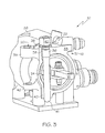
- FIG. 3 depicts a cross section view of the valve assembly of FIG. 1, shown in the locked position
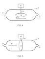
- FIG. 4 depicts a schematic view of a valve element used in the valve assembly of FIG. 1, shown in the full-open position;
- FIG. 5 depicts a schematic view of a valve element used in the valve assembly of FIG. 1, shown in the closed position
- FIG. 6 depicts a front perspective view of a lanyard for use in the valve assembly of FIG. 1.
- FIGs. 1-6 depict an exemplary embodiment of a valve assembly 10, and components thereof.
- the valve assembly 10 includes a valve body 12, a valve element 14, an actuator housing 16, an actuator 18, an unlocked storage opening 20, a locked storage opening 22, and a lock 24.
- the valve body 12 has an inlet port 28, an outlet port 30, and a flow passage 32 therebetween.
- the valve element 14 is movably disposed within the valve body flow passage 32, and is movable between a full-open position (depicted in FIG. 4), in which air or other fluid is allowed to flow through the valve body flow passage 32, and a closed position (depicted in FIG. 5), in which air or other fluid is restricted from flowing through the valve body flow passage 32.
- the valve element 14 may also be movable into intermediate positions between the full-open and closed positions, throttling fluid flow through the valve body flow passage 32.
- valve element 14 is a butterfly valve element.
- the valve element 14 may take any one of a number of different shapes, sizes and configurations.
- the fluid controlled by the valve assembly 10 is preferably air, but can also be any one of numerous other types of gases or other types of fluid.
- the actuator housing 16 preferably includes a main body 33 wherein the unlocked and locked storage openings 20, 22 are formed.
- the actuator 18 is disposed within the actuator housing 16, and preferably within the main body 33.
- the actuator 18 is coupled to the valve element 14 (not visible in FIGs. 1-3), and is operable to at least facilitate movement of the valve element 14, as described above.
- the actuator 18 may include, or may be coupled to, a shaft 34, which in turn is coupled to the valve element 14.
- the actuator 18 may take any one of a number of different shapes, sizes and configurations, and may move, or facilitate movement of, the valve element 14 in any one of a number of different ways. Regardless of the particular shape, size, configuration and operation of the actuator 18, the actuator 18 is at least partially disposed in the actuator housing 16.
- the unlocked storage opening 20 and the locked storage opening 22 are formed in the actuator housing 16, and are configured to allow storage of the lock 24 therein, so as to unlock or lock the valve assembly 10 as desired.
- the lock 24 is selectively insertable into, and movable between, the unlocked storage opening 20 and the locked storage opening 22.
- the lock does not engage the actuator 18, and valve movement is thereby allowed.
- the lock 24 engages at least a portion of the actuator 18, and valve movement is thereby at least inhibited, and preferably prevented.
- the unlocked and locked storage openings 20, 22 preferably include threads 36 on at least a portion of the respective inner surfaces. These threads 36 are configured to mate with like threads 36 that are formed on a portion of the outer surface of the lock 24 (as described below).
- the locked storage opening 22 preferably includes a helical insert 38, as shown in FIG. 3, to at least facilitate securing the lock 24 when it is placed in the unlocked and/or locked storage openings 2 0, 22.
- the helical insert 38 includes a plurality of helical coils, with one or more of the helical coils (preferably disposed approximately halfway along the helical insert 38 lengthwise) deformed to facilitate self-locking torque.
- the helical insert 38 helps the lock 24 to self-lock when in the unlocked and/or locked storage openings 20, 22. It will be appreciated that different embodiments for securing the lock 24 may be used in the unlocked storage opening 20 and/or the locked storage opening 22.
- the shape and size of the unlocked and locked storage openings 20, 22 are preferably configured to allow a close fit with the lock 24 when disposed therein, to make it easy to insert and move the lock 24 therebetween, and to help avoid unwanted vibration or movement of the lock 24.
- the unlocked and locked storage openings 20, 22 preferably each include at least a first wall 39, shaped at least in part to hold a cylindrical pin, an inner diameter preferably slightly larger than the diameter of the lock 24.
- the unlocked and locked storage openings 20, 22 also each include a second wall 40 with a similar shape, with a slightly smaller diameter and disposed beneath the first wall 39, to help further guide and retain the lock 24 into place.
- These walls may be manufactured separately or as a single unit on the actuator housing 16, for example through line drilling, in order to align the walls and to keep a tight fit between the lock 24 and the unlocked and locked storage openings 20, 22. It will be appreciated that, in other embodiments, different shapes, sizes, configurations, and methods of manufacture may be used. However, regardless of the particular shapes, sizes, configurations, and methods of manufacture, the unlocked and locked storage openings 20, 22 are configured to allow the lock 24 to be inserted therein and moved therebetween.
- the lock 24, as mentioned above, is selectively insertable into, and movable between, the unlocked storage opening 20 and the locked storage opening 22, and preferably has threads 36 configured to mate with the threads 36 formed in the unlocked and locked storage openings 20, 22.
- the lock 24 is preferably made of a high grade steel, such as Inconel 718.
- the lock 24 is in the shape of a cylindrical pin, with a diameter that forms a tight fit inside the unlocked and locked storage openings 20, 22.
- the lock 24 also preferably has a rounded end 41 configured to facilitate guiding the lock 24 down into the close fit created by the unlocked and locked storage openings 20, 22, and to help prevent wear on the lock 24.
- the lock 24 also preferably includes a head 42 configured to at least facilitate manual movement of the lock 24 into and between the unlocked and locked storage openings 20, 22.
- the head 42 is most preferably hexagonal in shape, so that the head 42 may be easily manipulated by a wrench with one hand, for example by application of torque with the wrench. Then, when it is loose, the lock 42 can be removed by one hand, for example through the use of a single finger and thumb.
- the lock 24 may not have a head 42 in certain embodiments, or may have a head 42 of a different shape, and/or that the lock 24 may otherwise have a different shape, size, or configuration, and/or be made of one or more different materials.
- the lock 24 is configured to engage at least a portion of the actuator 18 when the lock 24 is in the locked storage opening 22 (as depicted in FIGs. 1 and 3), thereby at least inhibiting, and preferably preventing, valve movement.
- the lock 24 allows valve movement when the lock 24 is in the unlocked storage opening 20 (as depicted in FIG. 2).
- the lock 24 may also include a lanyard 26.
- a larger, front perspective view of the lock 24 and lanyard 26 is provided in FIG. 6.
- the lanyard 26 is preferably attached to the lock 24 and coupled to the actuator housing 16, or other portion of the valve assembly 10.
- the lanyard 26 helps to ensure that the lock 24 is not inadvertently lost, for example during the process of manually moving the lock 24 into or between the unlocked or locked storage openings 20, 22.
- a lanyard 26 may not be used, or that the lanyard 26 may be attached to the lock 24 and/or the actuator housing 16 in a position or manner different from that depicted in FIGs. 1-3 and 6.
- the operation and use of the lock 24 is as follows, assuming that the lock 24 is initially in the unlocked storage opening 20, as depicted in FIG. 2.
- a torque can be applied to the head 42 of the lock, for example by hand with a wrench, to thereby un-mate the threads 36 on the lock 24 with the threads 36 formed in the unlocked storage opening 20.
- the lock 24 can then be manually moved out of the unlocked storage opening 20 and into the locked storage opening 22, for example by use of the same hand that first applied the torque to the head 42 of the lock 24.
- the optional lanyard 26 preferably remains screwed into the actuator housing 16, so that the lock 24 will not be lost in the unlikely event that the lock 24 is inadvertently or momentarily dropped.
- the threads 36 on the lock 24 are then mated with the threads 36 formed in the locked storage opening 22. Additionally, the lock 24 preferably further self-locks into place in the locked storage opening 22 by the helical insert 38 disposed therein. While in the locked storage opening 22, the lock 24 engages at least a portion of the actuator 18, and valve movement is thereby at least inhibited. Accordingly, the valve assembly 10 is thus locked in its current position.
- valve assembly 10 can be unlocked as follows.
- a torque can be applied to the head 42 of the lock 24, to thereby un-mate the threads 36 on the lock 24 with the threads 36 formed in the locked storage opening 22.
- the lock 24 can then be manually moved out of the locked storage opening 22 and into the unlocked storage opening 20, for example using similar methods as those described above.
- the threads 36 on the lock 24 are then mated with the threads 36 formed in the unlocked storage opening 20. Accordingly, the valve assembly 10 is thus unlocked, thereby allowing the actuator 18 to move the valve element 14 between the open, closed, and/or intermediate positions.
- valve assembly 10 allows the operator to lock and unlock the valve assembly 10, and thereby control movement of the valve element 14, easily with a single hand. More specifically, the configuration allows for such locking and unlocking in cases when only one hand is available, and/or when the valve assembly 10 is installed in an engine, for example onboard an airplane, and/or when visibility may be limited. Moreover, due to the self-locking mechanism of the lock 24, using the helical insert 38 of the locked storage opening 22, a user can manually accomplish the locking and unlocking process with the lock 24 without the need for screws, padlocks, or other components, thereby further simplifying the process.
Landscapes
- Engineering & Computer Science (AREA)
- General Engineering & Computer Science (AREA)
- Mechanical Engineering (AREA)
- Preventing Unauthorised Actuation Of Valves (AREA)
Abstract
Description
- The present invention generally relates to a valve assembly, and more specifically to a valve assembly with a lock.
- Valves are used to control air, gases or other fluids in various types of apparatus and vehicles, such as aircraft. For example, valves can be used to control the supply of bleed air on aircraft by opening, closing, or partially obstructing various passageways, among various other valve uses. There are many different types of valves used in aircraft, other vehicles, and other apparatus, such as butterfly valves, ball valves, and check valves, among others.
- By way of example only, a particular type of butterfly valve has a valve element positioned in the center of a flow passage, with a shaft connected thereto. The valve element is movable to an open position through movement of the shaft such that the valve element is parallel to the flow of air or other fluid, thereby allowing the flow of fluid through the valve passage. Conversely, the valve element is movable to a closed position through movement of the shaft such that the valve element is perpendicular to the flow of fluid, thereby restricting the flow of fluid through the valve passage. The shaft and the valve element can be movable in this manner through a spring force, pneumatic means, or some other means.
- In some instances, it may be desirable to include a manual mechanism for locking or unlocking the valve, for example in the highly unlikely event that some valve part may not function properly. It is also desirable for users, such as aircraft crew members, or operators of other vehicles or apparatus, to be able to lock or unlock the valve with a single hand, and/or where visibility may be impaired.
- Accordingly, there is a need for an assembly for locking or unlocking a valve, and for operators to be able to lock or unlock the valve with a single hand, and/or where visibility may be impaired. The present invention addresses one or more of these needs.
- An apparatus is provided for an assembly for a valve. In one embodiment, and by way of example only, the assembly is a valve assembly comprising a valve body, a valve element, an actuator housing, an actuator, an unlocked storage opening, a locked storage opening, and a lock. The valve body has an inlet port, an outlet port, and a flow passage therebetween. The valve element is movably disposed within the valve body flow passage. The actuator is disposed within the actuator housing, coupled to the valve element, and operable to move the valve. The unlocked storage opening and the locked storage opening are formed in the actuator housing. The lock is selectively insertable into, and movable between, the unlocked storage opening and the locked storage opening. When the lock is in the unlocked storage opening, the lock does not engage the actuator, and valve movement is thereby allowed. When the lock is in the locked storage opening, the lock engages at least a portion of the actuator, and valve movement is thereby at least inhibited.
- In another embodiment, and by way of example only, the assembly is an actuator assembly comprising an actuator housing, an actuator, an unlocked storage opening, a locked storage opening, and a lock. The actuator is disposed within the actuator housing, and is configured to couple to a valve element. The unlocked storage opening and the locked storage opening are formed in the actuator housing. The lock is selectively insertable into, and movable between, the unlocked storage opening and the locked storage opening. When the lock is in the unlocked storage opening, the lock does not engage the actuator. When the lock is in the locked storage opening, the lock engages at least a portion of the actuator.
- In yet another embodiment, and by way of example only, the assembly is an actuator housing comprising a main body, an unlocked storage opening, a locked storage opening, and a lock pin. The main body is configured to house an actuator. The unlocked storage opening and the locked storage opening are formed in the main body. The lock pin is selectively insertable into, and movable between, the unlocked storage opening and the locked storage opening. When the lock pin is in the unlocked storage opening, the lock pin does not engage the actuator. When the lock pin is in the locked storage opening, the lock pin engages at least a portion of the actuator.
- The present invention will hereinafter be described in conjunction with the following drawing figures, wherein like numerals denote like elements, and
- FIG. 1 depicts a front perspective view of a valve assembly with a lock, shown in the locked position;
- FIG. 2 depicts a front perspective view of the valve assembly of FIG. 1, shown in the unlocked position;
- FIG. 3 depicts a cross section view of the valve assembly of FIG. 1, shown in the locked position;
- FIG. 4 depicts a schematic view of a valve element used in the valve assembly of FIG. 1, shown in the full-open position;
- FIG. 5 depicts a schematic view of a valve element used in the valve assembly of FIG. 1, shown in the closed position; and
- FIG. 6 depicts a front perspective view of a lanyard for use in the valve assembly of FIG. 1.
- The following detailed description of the invention is merely exemplary in nature and is not intended to limit the invention or the application and uses of the invention. Furthermore, there is no intention to be bound by any theory presented in the preceding background of the invention or the following detailed description of the invention.
- FIGs. 1-6 depict an exemplary embodiment of a
valve assembly 10, and components thereof. Thevalve assembly 10 includes avalve body 12, avalve element 14, anactuator housing 16, anactuator 18, anunlocked storage opening 20, a lockedstorage opening 22, and alock 24. - Referring now to FIGs. 4 and 5, the
valve body 12 has aninlet port 28, anoutlet port 30, and aflow passage 32 therebetween. Thevalve element 14 is movably disposed within the valvebody flow passage 32, and is movable between a full-open position (depicted in FIG. 4), in which air or other fluid is allowed to flow through the valvebody flow passage 32, and a closed position (depicted in FIG. 5), in which air or other fluid is restricted from flowing through the valvebody flow passage 32. It will be appreciated by one of skill in the art that in certain embodiments thevalve element 14 may also be movable into intermediate positions between the full-open and closed positions, throttling fluid flow through the valvebody flow passage 32. Generally, the closer thevalve element 14 is to the full-open position, the more freely fluid is allowed to flow through the valvebody flow passage 32, thereby increasing fluid pressure in the valvebody flow passage 32 downstream of thevalve element 14. Conversely, the closer thevalve element 14 is to the closed position, the less freely fluid is allowed to flow through the valvebody flow passage 32, thereby decreasing fluid pressure in the valvebody flow passage 32 downstream of thevalve element 14. In the embodiment depicted in FIGs. 4 and 5, thevalve element 14 is a butterfly valve element. However, it will be appreciated that thevalve element 14 may take any one of a number of different shapes, sizes and configurations. Moreover, the fluid controlled by thevalve assembly 10 is preferably air, but can also be any one of numerous other types of gases or other types of fluid. - Returning now to FIGs. 1-3, the
actuator housing 16 is shown. As shown in FIGS. 1-3, the actuator housing 16 preferably includes amain body 33 wherein the unlocked and lockedstorage openings actuator 18 is disposed within theactuator housing 16, and preferably within themain body 33. Theactuator 18 is coupled to the valve element 14 (not visible in FIGs. 1-3), and is operable to at least facilitate movement of thevalve element 14, as described above. For example, in one preferred embodiment shown in FIGs. 4-5, theactuator 18 may include, or may be coupled to, ashaft 34, which in turn is coupled to thevalve element 14. However, it will be appreciated that theactuator 18 may take any one of a number of different shapes, sizes and configurations, and may move, or facilitate movement of, thevalve element 14 in any one of a number of different ways. Regardless of the particular shape, size, configuration and operation of theactuator 18, theactuator 18 is at least partially disposed in theactuator housing 16. - Returning again to FIGs. 1-3, the unlocked storage opening 20 and the locked
storage opening 22 are formed in theactuator housing 16, and are configured to allow storage of thelock 24 therein, so as to unlock or lock thevalve assembly 10 as desired. Thelock 24 is selectively insertable into, and movable between, the unlocked storage opening 20 and the locked storage opening 22. When thelock 24 is in the unlocked storage opening 20, as depicted in FIG. 2, the lock does not engage theactuator 18, and valve movement is thereby allowed. Conversely, when thelock 24 is in the locked storage opening 22, as depicted in FIGs. 1 and 3, thelock 24 engages at least a portion of theactuator 18, and valve movement is thereby at least inhibited, and preferably prevented. - The unlocked and locked
storage openings threads 36 on at least a portion of the respective inner surfaces. Thesethreads 36 are configured to mate with likethreads 36 that are formed on a portion of the outer surface of the lock 24 (as described below). In addition, the lockedstorage opening 22 preferably includes ahelical insert 38, as shown in FIG. 3, to at least facilitate securing thelock 24 when it is placed in the unlocked and/or locked storage openings 2 0, 22. Preferably, thehelical insert 38 includes a plurality of helical coils, with one or more of the helical coils (preferably disposed approximately halfway along thehelical insert 38 lengthwise) deformed to facilitate self-locking torque. Thehelical insert 38 helps thelock 24 to self-lock when in the unlocked and/or lockedstorage openings lock 24 may be used in theunlocked storage opening 20 and/or the lockedstorage opening 22. - The shape and size of the unlocked and locked
storage openings lock 24 when disposed therein, to make it easy to insert and move thelock 24 therebetween, and to help avoid unwanted vibration or movement of thelock 24. For example, in the depicted embodiment of acylindrical lock pin 24 with a specific diameter (as described below), the unlocked and lockedstorage openings first wall 39, shaped at least in part to hold a cylindrical pin, an inner diameter preferably slightly larger than the diameter of thelock 24. In a most preferred embodiment depicted in FIGs. 1-3, the unlocked and lockedstorage openings second wall 40 with a similar shape, with a slightly smaller diameter and disposed beneath thefirst wall 39, to help further guide and retain thelock 24 into place. These walls may be manufactured separately or as a single unit on theactuator housing 16, for example through line drilling, in order to align the walls and to keep a tight fit between thelock 24 and the unlocked and lockedstorage openings storage openings lock 24 to be inserted therein and moved therebetween. - The
lock 24, as mentioned above, is selectively insertable into, and movable between, theunlocked storage opening 20 and the lockedstorage opening 22, and preferably hasthreads 36 configured to mate with thethreads 36 formed in the unlocked and lockedstorage openings lock 24 is preferably made of a high grade steel, such as Inconel 718. - In the depicted embodiments, the
lock 24 is in the shape of a cylindrical pin, with a diameter that forms a tight fit inside the unlocked and lockedstorage openings lock 24 also preferably has arounded end 41 configured to facilitate guiding thelock 24 down into the close fit created by the unlocked and lockedstorage openings lock 24. Thelock 24 also preferably includes ahead 42 configured to at least facilitate manual movement of thelock 24 into and between the unlocked and lockedstorage openings head 42 is most preferably hexagonal in shape, so that thehead 42 may be easily manipulated by a wrench with one hand, for example by application of torque with the wrench. Then, when it is loose, thelock 42 can be removed by one hand, for example through the use of a single finger and thumb. - It will be appreciated that the
lock 24 may not have ahead 42 in certain embodiments, or may have ahead 42 of a different shape, and/or that thelock 24 may otherwise have a different shape, size, or configuration, and/or be made of one or more different materials. However, regardless of its particular shape, size, or configuration, or the material from which it is made, thelock 24 is configured to engage at least a portion of theactuator 18 when thelock 24 is in the locked storage opening 22 (as depicted in FIGs. 1 and 3), thereby at least inhibiting, and preferably preventing, valve movement. Conversely, thelock 24 allows valve movement when thelock 24 is in the unlocked storage opening 20 (as depicted in FIG. 2). - Turning now to FIG. 6, the
lock 24 may also include alanyard 26. A larger, front perspective view of thelock 24 andlanyard 26 is provided in FIG. 6. Thelanyard 26 is preferably attached to thelock 24 and coupled to theactuator housing 16, or other portion of thevalve assembly 10. Thelanyard 26 helps to ensure that thelock 24 is not inadvertently lost, for example during the process of manually moving thelock 24 into or between the unlocked or lockedstorage openings lanyard 26 may not be used, or that thelanyard 26 may be attached to thelock 24 and/or theactuator housing 16 in a position or manner different from that depicted in FIGs. 1-3 and 6. - The operation and use of the
lock 24 is as follows, assuming that thelock 24 is initially in theunlocked storage opening 20, as depicted in FIG. 2. A torque can be applied to thehead 42 of the lock, for example by hand with a wrench, to thereby un-mate thethreads 36 on thelock 24 with thethreads 36 formed in theunlocked storage opening 20. Thelock 24 can then be manually moved out of theunlocked storage opening 20 and into the lockedstorage opening 22, for example by use of the same hand that first applied the torque to thehead 42 of thelock 24. Theoptional lanyard 26 preferably remains screwed into theactuator housing 16, so that thelock 24 will not be lost in the unlikely event that thelock 24 is inadvertently or momentarily dropped. Thethreads 36 on thelock 24 are then mated with thethreads 36 formed in the lockedstorage opening 22. Additionally, thelock 24 preferably further self-locks into place in the lockedstorage opening 22 by thehelical insert 38 disposed therein. While in the lockedstorage opening 22, thelock 24 engages at least a portion of theactuator 18, and valve movement is thereby at least inhibited. Accordingly, thevalve assembly 10 is thus locked in its current position. - Conversely, the
valve assembly 10 can be unlocked as follows. A torque can be applied to thehead 42 of thelock 24, to thereby un-mate thethreads 36 on thelock 24 with thethreads 36 formed in the lockedstorage opening 22. Thelock 24 can then be manually moved out of the lockedstorage opening 22 and into theunlocked storage opening 20, for example using similar methods as those described above. Thethreads 36 on thelock 24 are then mated with thethreads 36 formed in theunlocked storage opening 20. Accordingly, thevalve assembly 10 is thus unlocked, thereby allowing theactuator 18 to move thevalve element 14 between the open, closed, and/or intermediate positions. - It will be appreciated that the configuration of the
valve assembly 10, and the various components thereof, can take any one of a number of different configurations. Regardless of the particular configuration, thevalve assembly 10 allows the operator to lock and unlock thevalve assembly 10, and thereby control movement of thevalve element 14, easily with a single hand. More specifically, the configuration allows for such locking and unlocking in cases when only one hand is available, and/or when thevalve assembly 10 is installed in an engine, for example onboard an airplane, and/or when visibility may be limited. Moreover, due to the self-locking mechanism of thelock 24, using thehelical insert 38 of the lockedstorage opening 22, a user can manually accomplish the locking and unlocking process with thelock 24 without the need for screws, padlocks, or other components, thereby further simplifying the process. - While at least one exemplary embodiment has been presented in the foregoing detailed description of the invention, it should be appreciated that a vast number of variations exist. It should also be appreciated that the exemplary embodiment or exemplary embodiments are only examples, and are not intended to limit the scope, applicability, or configuration of the invention in any way. Rather, the foregoing detailed description will provide those skilled in the art with a convenient road map for implementing an exemplary embodiment of the invention, it being understood that various changes may be made in the function and arrangement of elements described in an exemplary embodiment without departing from the scope of the invention as set forth in the appended claims and their legal equivalents.
Claims (10)
- A valve assembly (10), comprising:a valve body (12) having an inlet port (28), an outlet port (30), and a flow passage (32) therebetween;a valve element (14) movably disposed within the valve body flow passage (32); an actuator housing (16);an actuator (18) disposed within the actuator housing (16) and coupled to the valve element (14), the actuator (18) operable to move the valve element (14);an unlocked storage opening (20) formed in the actuator housing (16);a locked storage opening (22) formed in the actuator housing (16);a lock (24) selectively insertable into, and movable between, the unlocked storage opening (20) and the locked storage opening (22),wherein:when the lock (24) is in the unlocked storage opening (20), the lock (24) does not engage the actuator (18), and valve element (14) movement is thereby allowed, andwhen the lock (24) is in the locked storage opening (22), the lock (24) engages at least a portion of the actuator (18), and valve element (14) movement is thereby at least inhibited.
- The valve assembly (10) of Claim 1, further comprising:threads (36) disposed on the lock (24);threads (36) formed in the unlocked storage opening (20) and configured to mate with the threads (36) on the lock (24); andthreads (36) formed in the locked storage opening (22) and configured to mate with the threads (36) on the lock (24).
- The valve assembly (10) of Claim 1, further comprising:a helical insert (38) disposed at least in the locked storage opening (22) and configured to at least facilitate securing the lock (24) in the locked position when inserted into the locked storage opening (22).
- The valve assembly (10) of Claim 1, further comprising:a lanyard (26) attached to the lock (24) and coupled to the actuator housing (16).
- The valve assembly (10) of Claim 1, wherein the lock (24) comprises a pin (24).
- The valve assembly (10) of Claim 1, wherein the lock (24) comprises a head (42) configured to at least facilitate manual movement of the lock (24) into or between the unlocked and locked storage openings (20, 22).
- The valve assembly (10) of Claim 6, wherein the head (42) is hexagonal in shape.
- An actuator assembly (10), comprising:an actuator housing (16);an actuator (18) disposed within the actuator housing (16) and configured to couple to a valve element (14);an unlocked storage opening (20) formed in the actuator housing (16);a locked storage opening (22) formed in the actuator housing (16);a lock (24) selectively insertable into, and movable between, the unlocked storage opening (20) and the locked storage opening (22),wherein:when the lock (24) is in the unlocked storage opening (20), the lock (24) does not engage the actuator (18), andwhen the lock (24) is in the locked storage opening (22), the lock (24) engages at least a portion of the actuator (18).
- The actuator assembly (10) of Claim 8, further comprising:threads (36) disposed on the lock (24);threads (36) formed in the unlocked storage opening (20) and configured to mate with the threads (36) on the lock (24); andthreads (36) formed in the locked storage opening (22) and configured to mate with the threads (36) on the lock (24).
- The actuator assembly (10) of Claim 8, further comprising:a helical insert (38) disposed at least in the locked storage opening (22) and configured to at least facilitate securing the lock (24) in the locked position when inserted into the locked storage opening (22); anda lanyard (26) attached to the lock (24) and coupled to the actuator housing (16).
Applications Claiming Priority (1)
| Application Number | Priority Date | Filing Date | Title |
|---|---|---|---|
| US11/479,862 US7559528B2 (en) | 2006-06-30 | 2006-06-30 | Manual lock pin with lanyard |
Publications (1)
| Publication Number | Publication Date |
|---|---|
| EP1873434A1 true EP1873434A1 (en) | 2008-01-02 |
Family
ID=38564541
Family Applications (1)
| Application Number | Title | Priority Date | Filing Date |
|---|---|---|---|
| EP20070111274 Withdrawn EP1873434A1 (en) | 2006-06-30 | 2007-06-28 | Manual lock pin with lanyard |
Country Status (2)
| Country | Link |
|---|---|
| US (1) | US7559528B2 (en) |
| EP (1) | EP1873434A1 (en) |
Cited By (1)
| Publication number | Priority date | Publication date | Assignee | Title |
|---|---|---|---|---|
| JP2018523061A (en) * | 2015-05-12 | 2018-08-16 | インテグリス・インコーポレーテッド | Valve assembly and fluid storage / distribution package including the bubble assembly |
Families Citing this family (4)
| Publication number | Priority date | Publication date | Assignee | Title |
|---|---|---|---|---|
| US8210201B2 (en) * | 2008-03-17 | 2012-07-03 | Honeywell International Inc. | Regulator valve with locking system |
| US8459609B2 (en) * | 2009-12-28 | 2013-06-11 | Honeywell International Inc. | Butterfly valve assembly incorporating a unitary shaft and butterfly plate valve element |
| US8806906B1 (en) * | 2011-12-29 | 2014-08-19 | Bryce M. Bagby | Actuator lock-out bracket |
| US9217514B1 (en) | 2011-12-29 | 2015-12-22 | Bryce M. Bagby | Actuator lock-out bracket |
Citations (6)
| Publication number | Priority date | Publication date | Assignee | Title |
|---|---|---|---|---|
| FR2638218A1 (en) * | 1988-10-26 | 1990-04-27 | Tilles Ste Mecanique | Gas cylinder tap (valve) |
| US5370148A (en) * | 1994-04-25 | 1994-12-06 | Shafer; Terry C. | Butterfly valve assembly and method of manufacture |
| WO2000050793A1 (en) | 1999-02-24 | 2000-08-31 | Water Valves Australia Pty. Ltd. | Water meter fixtures |
| US6196268B1 (en) * | 1999-12-23 | 2001-03-06 | Tm Industrial Supply, Inc. | Rising stem soft seat plug valve |
| US6205826B1 (en) * | 1994-10-03 | 2001-03-27 | Neelchine Engineering, Inc. | Lockout device |
| WO2002079680A1 (en) | 2001-03-30 | 2002-10-10 | Shuter Charles Frederick Thoma | Valve locking device |
Family Cites Families (17)
| Publication number | Priority date | Publication date | Assignee | Title |
|---|---|---|---|---|
| US3743239A (en) | 1971-12-03 | 1973-07-03 | J Heckrotte | Lock-off valve |
| US4458510A (en) | 1980-12-15 | 1984-07-10 | Omco Inc. | Locking device for a winged gas stop |
| US5046523A (en) | 1989-06-02 | 1991-09-10 | George Horhota | Lock core service valve |
| US4971289A (en) | 1989-11-29 | 1990-11-20 | Niagara Mohawk Power Corporation | Valve assembly and locking means therefor |
| US5116018A (en) | 1991-04-12 | 1992-05-26 | Automax, Inc. | Lockout modules |
| US5190263A (en) * | 1992-04-08 | 1993-03-02 | Neles-Jamesbury, Inc. | Locking mechanism for an actuator |
| US5329959A (en) * | 1992-10-29 | 1994-07-19 | Bettis Corporation | Locking device |
| US6361017B1 (en) | 1999-11-19 | 2002-03-26 | Spencer M. Nimberger | Locking valve with joint allowing packing service |
| DE10006326A1 (en) * | 2000-02-12 | 2001-08-16 | Gemue Gebr Mueller Appbau Gmbh | Manual drive for shut-off devices |
| CA2344527A1 (en) | 2000-05-02 | 2001-11-02 | Frederick Le Page | Assembly security lock for shut-off valve |
| US6640688B1 (en) | 2000-08-25 | 2003-11-04 | Tyco Flow Control, Inc. | Actuator assembly |
| US6598850B2 (en) | 2000-10-19 | 2003-07-29 | Henry Pratt Company | Butterfly valve locking apparatus |
| US6273125B1 (en) | 2000-11-01 | 2001-08-14 | Spx Corporation | Compression key lockout device for a gate valve |
| US6398184B1 (en) | 2000-12-29 | 2002-06-04 | General Signal Corporation | Lock device and lock method for knife gate valves |
| US6935610B1 (en) | 2003-01-17 | 2005-08-30 | Dynatorque, Inc. | Partial stroke valve test apparatus |
| US6896239B1 (en) | 2003-04-22 | 2005-05-24 | Arthur J. Brenes | Method and apparatus for locking a valve |
| US7219685B1 (en) * | 2004-06-22 | 2007-05-22 | Roger Espinoza | Gate valve locking device |
-
2006
- 2006-06-30 US US11/479,862 patent/US7559528B2/en active Active
-
2007
- 2007-06-28 EP EP20070111274 patent/EP1873434A1/en not_active Withdrawn
Patent Citations (6)
| Publication number | Priority date | Publication date | Assignee | Title |
|---|---|---|---|---|
| FR2638218A1 (en) * | 1988-10-26 | 1990-04-27 | Tilles Ste Mecanique | Gas cylinder tap (valve) |
| US5370148A (en) * | 1994-04-25 | 1994-12-06 | Shafer; Terry C. | Butterfly valve assembly and method of manufacture |
| US6205826B1 (en) * | 1994-10-03 | 2001-03-27 | Neelchine Engineering, Inc. | Lockout device |
| WO2000050793A1 (en) | 1999-02-24 | 2000-08-31 | Water Valves Australia Pty. Ltd. | Water meter fixtures |
| US6196268B1 (en) * | 1999-12-23 | 2001-03-06 | Tm Industrial Supply, Inc. | Rising stem soft seat plug valve |
| WO2002079680A1 (en) | 2001-03-30 | 2002-10-10 | Shuter Charles Frederick Thoma | Valve locking device |
Cited By (3)
| Publication number | Priority date | Publication date | Assignee | Title |
|---|---|---|---|---|
| JP2018523061A (en) * | 2015-05-12 | 2018-08-16 | インテグリス・インコーポレーテッド | Valve assembly and fluid storage / distribution package including the bubble assembly |
| EP3295075A4 (en) * | 2015-05-12 | 2019-03-20 | Entegris, Inc. | VALVE ASSEMBLIES AND FLUID DISPENSING AND DISPENSING PACKS INCLUDING THE SAME |
| TWI680923B (en) * | 2015-05-12 | 2020-01-01 | 美商恩特葛瑞斯股份有限公司 | Valve assemblies and fluid storage and dispensing packages comprising same |
Also Published As
| Publication number | Publication date |
|---|---|
| US7559528B2 (en) | 2009-07-14 |
| US20080001109A1 (en) | 2008-01-03 |
Similar Documents
| Publication | Publication Date | Title |
|---|---|---|
| US9097622B2 (en) | Process interface valve assembly | |
| EP2809977B1 (en) | Manual overrides for valves | |
| JP2019044788A (en) | Rotary valve | |
| CN105370968B (en) | For centre of sphere valve module without instrument stem connector component | |
| US6718804B1 (en) | Valve lockout device | |
| US20150114471A1 (en) | Valve Lock | |
| US7559528B2 (en) | Manual lock pin with lanyard | |
| US20050035325A1 (en) | Diaphragm valve having adjustable closure means | |
| US5411048A (en) | Fluid control valve with latching handle assembly | |
| DE9005826U1 (en) | Shut-off device for a pressure vessel under internal pressure of a medium | |
| US20120071083A1 (en) | Locking damper positioner | |
| WO2010062552A1 (en) | A microfluidic valve mechanism | |
| JP2012057651A (en) | Opening-closing position lock device of valve | |
| US20030217571A1 (en) | Tamper resistant lock shield for valve | |
| JPH04341273A (en) | Mechanism for connecting outlet for medical use | |
| US6893002B2 (en) | Lockout valve | |
| US1801175A (en) | Cock or valve | |
| JP2009281527A (en) | Relief valve | |
| DE102017206193B3 (en) | Shut-off valve for a fluid system | |
| KR102344673B1 (en) | Manual valve and pneumatic device | |
| EP1074772B1 (en) | Ball valve with key-operated lock | |
| EP1850042A2 (en) | Angled poppet valve manual override mechanism | |
| JP2009243546A (en) | Lock structure of rotary valve | |
| EP0959283B1 (en) | Valve | |
| US20090057584A1 (en) | Lockable Sampling Valve |
Legal Events
| Date | Code | Title | Description |
|---|---|---|---|
| PUAI | Public reference made under article 153(3) epc to a published international application that has entered the european phase |
Free format text: ORIGINAL CODE: 0009012 |
|
| AK | Designated contracting states |
Kind code of ref document: A1 Designated state(s): AT BE BG CH CY CZ DE DK EE ES FI FR GB GR HU IE IS IT LI LT LU LV MC MT NL PL PT RO SE SI SK TR |
|
| AX | Request for extension of the european patent |
Extension state: AL BA HR MK YU |
|
| 17P | Request for examination filed |
Effective date: 20080620 |
|
| 17Q | First examination report despatched |
Effective date: 20080724 |
|
| AKX | Designation fees paid |
Designated state(s): DE FR GB |
|
| STAA | Information on the status of an ep patent application or granted ep patent |
Free format text: STATUS: THE APPLICATION IS DEEMED TO BE WITHDRAWN |
|
| 18D | Application deemed to be withdrawn |
Effective date: 20120103 |