EP1873413A1 - Yoke for universal joint and universal joint - Google Patents
Yoke for universal joint and universal joint Download PDFInfo
- Publication number
- EP1873413A1 EP1873413A1 EP07011591A EP07011591A EP1873413A1 EP 1873413 A1 EP1873413 A1 EP 1873413A1 EP 07011591 A EP07011591 A EP 07011591A EP 07011591 A EP07011591 A EP 07011591A EP 1873413 A1 EP1873413 A1 EP 1873413A1
- Authority
- EP
- European Patent Office
- Prior art keywords
- base
- yoke
- arms
- center
- axis
- Prior art date
- Legal status (The legal status is an assumption and is not a legal conclusion. Google has not performed a legal analysis and makes no representation as to the accuracy of the status listed.)
- Granted
Links
Images




Classifications
-
- F—MECHANICAL ENGINEERING; LIGHTING; HEATING; WEAPONS; BLASTING
- F16—ENGINEERING ELEMENTS AND UNITS; GENERAL MEASURES FOR PRODUCING AND MAINTAINING EFFECTIVE FUNCTIONING OF MACHINES OR INSTALLATIONS; THERMAL INSULATION IN GENERAL
- F16D—COUPLINGS FOR TRANSMITTING ROTATION; CLUTCHES; BRAKES
- F16D3/00—Yielding couplings, i.e. with means permitting movement between the connected parts during the drive
- F16D3/16—Universal joints in which flexibility is produced by means of pivots or sliding or rolling connecting parts
- F16D3/26—Hooke's joints or other joints with an equivalent intermediate member to which each coupling part is pivotally or slidably connected
- F16D3/38—Hooke's joints or other joints with an equivalent intermediate member to which each coupling part is pivotally or slidably connected with a single intermediate member with trunnions or bearings arranged on two axes perpendicular to one another
- F16D3/382—Hooke's joints or other joints with an equivalent intermediate member to which each coupling part is pivotally or slidably connected with a single intermediate member with trunnions or bearings arranged on two axes perpendicular to one another constructional details of other than the intermediate member
- F16D3/387—Fork construction; Mounting of fork on shaft; Adapting shaft for mounting of fork
Definitions
- the present invention relates to a yoke for universal joint and a universal joint.
- an intermediate shaft for connecting a steering shaft and a steering gear such as a rack and pinion mechanism has a function to contract following the retraction of the steering gear when a vehicle collides against a front object (at primary collision). This prevents an impact of the primary collision from being transferred to a steering member such as a steering wheel.
- a universal joint connecting the intermediate shaft with the steering gear and the steering shaft assumes a greater bend angle (e.g., a bend angle on the order of 60°) than a bend angle thereof while the vehicle is moving.
- the universal joint is required to secure the above bend angle with respect to the overall range of rotational angle of the steering member.
- a yoke for universal joint which is formed by punching out a sheet metal and press forming the resultant sheet metal (see, for example, Japanese Unexamined Patent Publication No. 2005-163866 ).
- the intermediate shaft is designed to bear a greater load and hence, higher rigidity is required for the yoke for universal joint.
- the yoke may suffer poor rigidity if the yoke is decreased in thickness in order to provide for the increase of the bend angle.
- a preferred embodiment of the present invention provides a yoke for universal joint formed by punching out a sheet metal and press forming the resultant sheet metal.
- the yoke for universal joint comprising a cylindrical base for fixing a shaft; and a pair of arms extending from an end of the base in parallel to a center axis of the base and swingablly connected with a counterpart yoke via a cross shaft.
- Each of the arms is formed with a support hole for supporting a corresponding trunnion of the cross shaft via a bearing.
- the support hole of each of the arms has a center axis extending in a direction orthogonal to the center axis of the base.
- the end of the base is formed with a relief portion including a concave curved surface.
- the concave curved surface of the relief portion at the end of the base has a center of curvature located at place offset from a center of the joint toward a distal end of the arm.
- the relief portion at the end of the base, shaped in a concave spherical surface and having a concentric relation with the center of the joint, and to define a radius of the concave spherical surface to be greater than a radius of the swing motion of the counterpart yoke.
- the relief portion intersects with the base at an acute angle, so that the end of the base is decreased in thickness. Therefore, the yoke has a drawback of low rigidity.
- the relief portion formed at the end of the base and including the concave curved surface has the center of curvature located at place offset from the center of the joint toward the distal end of the arm. That is, the embodiment adopts a layout wherein the concave curved surface of the relief portion is in a non-concentric relation with the center of the joint.
- the embodiment is adapted to overcome the above drawback and to attain an advantage to increase the bend angle while increasing rigidity.
- the concave curved surface of the relief portion may have the center of curvature located at place on the center axis of the base and otherwise.
- a normal line of the concave curved surface of the relief portion only need to have a point closest to the center axis of the base offset from the center of the joint toward the distal end of the arm.
- the universal joint 1 includes: a first yoke 4 as a yoke for universal joint connected with the first shaft 2; a second yoke 5 as another yoke (counterpart yoke) connected with the second shaft 3; and a cross shaft 6 interconnecting the first yoke 4 and the second yoke 5.
- the first and second yokes 4, 5 have the same constitution and each support each corresponding pair of trunnions 7 via a bearing 8 such as a needle roller bearing.
- FIG.2 is a perspective view of the first yoke 4.
- FIG.3 is a partly cut-away front view of the first yoke 4, and
- FIG. 4 is a vertical sectional view of the first yoke 4.
- Each of the arms 11 is formed with a support hole 12 for supporting a corresponding trunnion 7 of the cross shaft 6 via the bearing 8.
- Each of the support holes 12 has a center axis 13 extending in a direction orthogonal to the center axis 10 of the base 9.
- the first end 9a of the cylindrical base 9 is formed with a first relief portion 14 including a concave curved surface.
- the first relief portion 14 defines a concave spherical surface.
- a part of or the all of the first relief portion 14 is defined by a sphere (curvature radius R1) in a non-concentric relation with a center C1 of the joint 1.
- the concave spherical surface defined by the first relief portion 14 has a center of curvature A1 located between the center C1 of the joint 1 and a distal end of the arm 11 on the center axis 10 of the base 9.
- the concave spherical surface (concave curved surface) constituting the first relief portion 14 has the center of curvature A1 thereof offset from the center C1 of the joint 1 toward the distal end of the arm 11.
- Each of the arms 11 includes: an outside surface 15; an inside surface 16; and an edge portion 17 having an inverted-U shape.
- the edge portion 17 of each arm 11 includes a pair of side edges 17a substantially extending in parallel to the center axis 10 of the base 9.
- the inside surface 16 is formed with a gutter-like concave groove 16a extending in parallel to the center axis 10 of the base 9.
- Each side edge 17a is formed with a second relief portion 18 including a flat plane defining a parallelogram.
- a chamfer 22 for relief is formed on the overall length of a ridge 21 between the edge portion 17 having the inverted-U shape and the outside surface 15 of each arm 11 such that stress concentration on the arm 11 may be alleviated.
- the chamfer 22 is continuous to the first relief portion 14 at the first end 9a of the base 9 so that stress concentration generated on a root of the arm 11 may be alleviated to increase rigidity and durability.
- the second relief portions 18 of the pair of the side edges 17a of the arm 11 have a width W1 or the width W1 between the relief portions 18 of the pair of side edges 17a) progressively decreased toward the center axis 10 of the base 9, as shown in FIG. 6 showing a section taken on the line VI-VI in FIG. 4 . Accordingly, the interference between the corresponding side edges 17a of the yokes 4, 5 can be effectively prevented, so that the yokes are adapted to achieve the great bend angle (e.g., 60°).
- the great bend angle e.g. 60°
- FIG.7A to 7D and FIG.8 an exemplary procedure of forming the first yoke 4 by punching out and by press forming is described with reference to FIG.7A to 7D and FIG.8.
- a lower hole 32 drilled through an elongate sheet metal 31 is expanded by burring, as shown in FIG.7A.
- a periphery of the lower hole 32 is extruded in one direction, whereby a cylindrical portion 33 is formed.
- the burring process may be replaced by drawing.
- a blank as an intermediate member 34 having a predetermined outside shape is formed by a trimming process.
- the blank as an intermediate member 34 includes: a first portion 35 to form the base formed around the cylindrical portion 33 and designed; and a pair of second portions 36 to form the arms sandwiching the first portion 35 therebetween and extending in mutually opposite directions.
- a coining process is performed to form portions 16a' , 14', 18' and 22' on each of the second portions 36 such that these portions 16a', 14', 18' and 22' constitute the concave groove 16a, the first relief portion 14, the second relief portion 18 and the chamfer 22, respectively.
- the cylindrical portion 33 is subjected to drawing a process into a shaped portion 9' approximate to the base 9. While the pair of second portions 36 are bent to form portions 11' approximate to the pair of arms 11 by a bending process.
- FIG.9 schematically shows a state where the universal joint 1 achieves the maximum bend angle of 60°.
- FIG.9 omits the cross shaft.
- both the yokes 4, 5 encounter the severest conditions for the interference between the corresponding arms 11 thereof.
- the first rotational direction P1 and the second rotational direction Q1 are directed opposite to each other.
- an advantage can be obtained to increase the bend angle and the rigidity of the joint 1 because the first relief portion 14 formed at the first end 9a of the base 9 and defined by the concave curved surface has the center of curvature A1 located at place offset from the center C1 of the joint 1 toward the distal end of the arm 11.
- the width W1 of the arm 11 with respect to the direction parallel to the direction K1 orthogonal to the center axis 10 of the base 9 and the center axis 13 of the support hole 12 is progressively decreased toward the center axis 10 of the base 9, as shown in FIG.6. Therefore, the interference between the corresponding side edges 17a of the yokes 4, 5 may be effectively avoided. Hence, the yokes can achieve the great bend angle (e.g., 60°).
- the second relief portion 18 of each side edge 17a includes the flat plane defining the parallelogram.
- the flat plane intersects with the corresponding side edge 17a of the corresponding arm 11 on the first intersection 19 and the second intersection 20 extending in parallel to the center axis 10 of the base 9.
- the first intersection 19 is relatively closer to the center axis 10 of the base 9, whereas the second intersection 20 is relatively farther from the center axis 10 of the base 9.
- the first intersection 19 is relatively farther from the center C1 of the joint 1
- the second intersection 20 is relatively closer to the center C1 of the joint 1.
- the relief is only provided at the necessary areas of the arms 11 such as to avoid the interference with the counterpart yoke 5.
- the joint 1 can achieve the great bend angle (e.g., 60°) while securing the strength of the arms 11.
- the chamfer 22 for relief is formed on the overall length of the ridge 21 between the outside surface 15 of each arm 11 and the edge portion 17 having the inverted-U shape. Hence, the stress concentration on the arm 11 may be effectively alleviated.
- the above chamfer 22 is formed continuous to the first relief portion 14 at the first end 9a of the base 9. Therefore, the yoke 4 may decrease in the stress concentration generated on the root of the arm 11, thereby achieving to increase strength and durability.
- the length of the arm 11 is shortened such that the distance L1 from the center C1 of the joint 1 to the first end 9a of the base 9 does not exceed the maximum radius of rotation R2 of the base 9, thereby securing the rigidity of the arm 11.
- the arm 11 can secure the determined rigidity so that the controllability may be secured.
Landscapes
- Engineering & Computer Science (AREA)
- General Engineering & Computer Science (AREA)
- Mechanical Engineering (AREA)
- Steering Controls (AREA)
- Vehicle Body Suspensions (AREA)
- Forging (AREA)
- Power Steering Mechanism (AREA)
Abstract
Description
- The present invention relates to a yoke for universal joint and a universal joint.
- In an automotive steering system, for example, an intermediate shaft for connecting a steering shaft and a steering gear such as a rack and pinion mechanism has a function to contract following the retraction of the steering gear when a vehicle collides against a front object (at primary collision). This prevents an impact of the primary collision from being transferred to a steering member such as a steering wheel.
- When the intermediate shaft is contracted at the primary collision, a universal joint connecting the intermediate shaft with the steering gear and the steering shaft assumes a greater bend angle (e.g., a bend angle on the order of 60°) than a bend angle thereof while the vehicle is moving.
- Since the steering member may be turned at any steering angle at the primary collision, the universal joint is required to secure the above bend angle with respect to the overall range of rotational angle of the steering member.
- On the other hand, a yoke for universal joint has been proposed which is formed by punching out a sheet metal and press forming the resultant sheet metal (see, for example,
Japanese Unexamined Patent Publication No. 2005-163866 - In an electronic power steering device having an electric motor for power assist disposed at a steering column, on the other hand, the intermediate shaft is designed to bear a greater load and hence, higher rigidity is required for the yoke for universal joint.
- In a case where the press molded yoke is used as the yoke for universal joint, the yoke may suffer poor rigidity if the yoke is decreased in thickness in order to provide for the increase of the bend angle.
- It is an object of the invention to provide a yoke for universal joint and a universal joint which feature a high rigidity and can secure a greater bend angle.
- In order to achieve foregoing object, a preferred embodiment of the present invention provides a yoke for universal joint formed by punching out a sheet metal and press forming the resultant sheet metal. The yoke for universal joint comprising a cylindrical base for fixing a shaft; and a pair of arms extending from an end of the base in parallel to a center axis of the base and swingablly connected with a counterpart yoke via a cross shaft. Each of the arms is formed with a support hole for supporting a corresponding trunnion of the cross shaft via a bearing. The support hole of each of the arms has a center axis extending in a direction orthogonal to the center axis of the base. The end of the base is formed with a relief portion including a concave curved surface. The concave curved surface of the relief portion at the end of the base has a center of curvature located at place offset from a center of the joint toward a distal end of the arm.
- In order to avoid interference between the end of the base of the yoke for universal joint and a distal end of a counterpart yoke, it may be possible to provide the relief portion at the end of the base, shaped in a concave spherical surface and having a concentric relation with the center of the joint, and to define a radius of the concave spherical surface to be greater than a radius of the swing motion of the counterpart yoke. In this case, however, the relief portion intersects with the base at an acute angle, so that the end of the base is decreased in thickness. Therefore, the yoke has a drawback of low rigidity.
- According to the embodiment, on the other hand, the relief portion formed at the end of the base and including the concave curved surface has the center of curvature located at place offset from the center of the joint toward the distal end of the arm. That is, the embodiment adopts a layout wherein the concave curved surface of the relief portion is in a non-concentric relation with the center of the joint. Thus, the embodiment is adapted to overcome the above drawback and to attain an advantage to increase the bend angle while increasing rigidity.
- It should be noted that the concave curved surface of the relief portion may have the center of curvature located at place on the center axis of the base and otherwise. In a case where the concave curved surface of the relief portion does not have the center of curvature located at place on the center axis of the base, a normal line of the concave curved surface of the relief portion only need to have a point closest to the center axis of the base offset from the center of the joint toward the distal end of the arm.
-
- FIG.1 is a front view of a universal joint for showing a state where the universal joint including a yoke according to one embodiment of the invention is connected with shafts;
- FIG.2 is a schematic perspective view of the yoke;
- FIG.3 is a partly cut-away front view of the yoke;
- FIG.4 is a vertical sectional view of the yoke;
- FIG.5 is a sectional view showing a principal part of an arm of the yoke;
- FIG.6 is a sectional view taken on the line VI-VI in FIG.4;
- FIG.7A, FIG.7B, FIG.7C and FIG.7D are a group of schematic perspective views showing the steps of forming the yoke from a sheet metal, in this order;
- FIG.8 is a schematic perspective view of an intermediary body for yoke manufacture;
- FIG.9 is a schematic perspective view showing the universal joint at the maximum bend angle; and
- FIG. 10 is a schematic diagram showing a principal part of corresponding arms of the yokes at the maximum bend angle.
- A preferred embodiment of the invention will be described with reference to the accompanying drawings.
- FIG. 1 is a schematic side view showing a universal joint employing a yoke for universal joint according to one embodiment of the invention. Referring to FIG.1, a
universal joint 1 connects afirst shaft 2 and asecond shaft 3. Thefirst shaft 2 comprises, for example, a steering shaft of an automotive vehicle, whereas thesecond shaft 3 comprises, for example, an intermediate shaft for connecting the steering shaft and a steering mechanism such as a rack and pinion mechanism. - The
universal joint 1 includes: afirst yoke 4 as a yoke for universal joint connected with thefirst shaft 2; asecond yoke 5 as another yoke (counterpart yoke) connected with thesecond shaft 3; and across shaft 6 interconnecting thefirst yoke 4 and thesecond yoke 5. - The first and
second yokes trunnions 7 via abearing 8 such as a needle roller bearing. - The following description is made with reference to the
first yoke 4. FIG.2 is a perspective view of thefirst yoke 4. FIG.3 is a partly cut-away front view of thefirst yoke 4, and FIG. 4 is a vertical sectional view of thefirst yoke 4. - Referring to FIG.1 and FIG.3, the
first yoke 4 is formed by punching out a sheet metal having a thickness of 6 to 9mm, for example, and by press molding the resultant the sheet metal. Thefirst yoke 4 includes: acylindrical base 9 for fixing the yoke to the shaft; and a pair ofarms 11 provided to extend from afirst end 9a of thebase 9 in parallel to acenter axis 10 of thebase 9, and to oppose each other. - Each of the
arms 11 is formed with asupport hole 12 for supporting acorresponding trunnion 7 of thecross shaft 6 via thebearing 8. Each of thesupport holes 12 has acenter axis 13 extending in a direction orthogonal to thecenter axis 10 of thebase 9. - Referring to FIG.2 and FIG.4, the
first end 9a of thecylindrical base 9 is formed with afirst relief portion 14 including a concave curved surface. Specifically, thefirst relief portion 14 defines a concave spherical surface. For instance, a part of or the all of thefirst relief portion 14 is defined by a sphere (curvature radius R1) in a non-concentric relation with a center C1 of thejoint 1. - The concave spherical surface defined by the
first relief portion 14 has a center of curvature A1 located between the center C1 of thejoint 1 and a distal end of thearm 11 on thecenter axis 10 of thebase 9. In other words, the concave spherical surface (concave curved surface) constituting thefirst relief portion 14 has the center of curvature A1 thereof offset from the center C1 of thejoint 1 toward the distal end of thearm 11. - Each of the
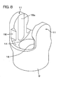
arms 11 includes: anoutside surface 15; aninside surface 16; and anedge portion 17 having an inverted-U shape. Theedge portion 17 of eacharm 11 includes a pair ofside edges 17a substantially extending in parallel to thecenter axis 10 of thebase 9. Theinside surface 16 is formed with a gutter-likeconcave groove 16a extending in parallel to thecenter axis 10 of thebase 9. Eachside edge 17a is formed with asecond relief portion 18 including a flat plane defining a parallelogram. - The flat plane of the
second relief portion 18 and thecorresponding side edge 17a of thecorresponding arm 11 intersect each other on first andsecond intersections center axis 10 of thebase 9. Theseintersections first intersection 19 is relatively closer to thecenter axis 10 of thebase 9, whereas thesecond intersection 20 is relatively farther from thecenter axis 10 of thebase 9. With respect to a direction parallel to thecenter axis 10 of thebase 9, thefirst intersection 19 is relatively farther from the center C1 of thejoint 1, whereas thesecond intersection 20 is relatively closer to the center C1 of thejoint 1. In this manner, thearm 11 is provided with relief at only necessary areas for avoiding interference with thecounterpart yoke 5. Thus, the joint 1 can achieve a great bend angle (e.g., 60°) while securing high rigidity of thearms 11. - As shown in FIG.5, a
chamfer 22 for relief is formed on the overall length of aridge 21 between theedge portion 17 having the inverted-U shape and theoutside surface 15 of eacharm 11 such that stress concentration on thearm 11 may be alleviated. Thechamfer 22 is continuous to thefirst relief portion 14 at thefirst end 9a of thebase 9 so that stress concentration generated on a root of thearm 11 may be alleviated to increase rigidity and durability. - The distance L1 from the center C1 of the joint 1 to the
first end 9a of thebase 9 is designed not to exceed the maximum radius of rotation R2 of the base 9 (namely, L1≤R2) . In this manner, thearm 11 is designed to have a short length thereby securing the rigidity. - The maximum thickness T1 (see FIG.6) of the
arm 11 is defined to be at least 15% of the maximum diameter of rotation D1 (D1=2×R2) of the base 9 (namely, T1≥0.15×D1). Thus, thearm 11 can secure a determined rigidity so that controllability may be secured. - With respect to a direction parallel to a direction K1 orthogonal to the
center axis 10 of thebase 9 and thecenter axis 13 of thesupport hole 12, thesecond relief portions 18 of the pair of the side edges 17a of thearm 11 have a width W1 or the width W1 between therelief portions 18 of the pair ofside edges 17a) progressively decreased toward thecenter axis 10 of thebase 9, as shown in FIG. 6 showing a section taken on the line VI-VI in FIG. 4 . Accordingly, the interference between the corresponding side edges 17a of theyokes - Next, an exemplary procedure of forming the
first yoke 4 by punching out and by press forming is described with reference to FIG.7A to 7D and FIG.8. First, alower hole 32 drilled through anelongate sheet metal 31 is expanded by burring, as shown in FIG.7A. A periphery of thelower hole 32 is extruded in one direction, whereby acylindrical portion 33 is formed. The burring process may be replaced by drawing. - Subsequently, as shown in FIG. 7B, a blank as an
intermediate member 34 having a predetermined outside shape is formed by a trimming process. The blank as anintermediate member 34 includes: afirst portion 35 to form the base formed around thecylindrical portion 33 and designed; and a pair ofsecond portions 36 to form the arms sandwiching thefirst portion 35 therebetween and extending in mutually opposite directions. - Next, as shown in FIG.7C, a coining process is performed to form
portions 16a' , 14', 18' and 22' on each of thesecond portions 36 such that theseportions 16a', 14', 18' and 22' constitute theconcave groove 16a, thefirst relief portion 14, thesecond relief portion 18 and thechamfer 22, respectively. - As shown in FIG.7D, the
cylindrical portion 33 is subjected to drawing a process into a shaped portion 9' approximate to thebase 9. While the pair ofsecond portions 36 are bent to form portions 11' approximate to the pair ofarms 11 by a bending process. - Subsequently, by shaping and coining processes the
base 9 and the pair ofarms 11 are formed as shown in FIG.8. - Next, an inner periphery of the
base 9 is subjected to serration, while each of thearms 11 is machined to form thesupport hole 12 therethrough, whereby thefirst yoke 4 is obtained as shown in FIG.2. - FIG.9 schematically shows a state where the
universal joint 1 achieves the maximum bend angle of 60°. FIG.9 omits the cross shaft. - A first axis P is an axis of the paired
trunnions 7 connected with the first yoke 4 (equivalent to thecenter axis 13 of the support holes 12 of the first yoke 4). A second axis Q is an axis orthogonal to both the above first axis P and arotation axis 4a of thefirst yoke 4. - In a state where the
second yoke 5 is rotationally shifted from an unbent state about the first axis P in a first rotational direction P1 through a rotational angle α (α=45°) and as rotated about the second axis Q in a second direction Q1 through a rotational angle β (β=45°), both theyokes arms 11 thereof. The first rotational direction P1 and the second rotational direction Q1 are directed opposite to each other. - As schematically shown in FIG.10, the embodiment is designed such that the flat plane as the
second relief portion 18 of thearm 11 of thefirst yoke 4 and the flat plane as thesecond relief portion 18 of thecorresponding arm 11 of thesecond yoke 5 are positioned in a parallel relation via a predetermined gap therebetween when these yokes are subjected to the severest conditions for the interference between these arms. Accordingly, the interference between the correspondingarms 11 of theseyokes arms 11. As a result, theuniversal joint 1 is adapted to secure the great bend angle while securing the secure strength thereof. - According to the embodiment, an advantage can be obtained to increase the bend angle and the rigidity of the joint 1 because the
first relief portion 14 formed at thefirst end 9a of thebase 9 and defined by the concave curved surface has the center of curvature A1 located at place offset from the center C1 of the joint 1 toward the distal end of thearm 11. - It should be noted that the center of curvature A1 of the
first relief portion 14 need not necessarily be located on thecenter axis 10 of thebase 9. In a case where the center of curvature A1 of thefirst relief portion 14 is not located on thecenter axis 10 of thebase 9, a normal line of thefirst relief portion 14 having a position closest to thecenter axis 10 of thebase 9 may be offset from the center C1 of the joint 1 toward the distal end of thearm 11. - In the
second relief portion 18 provided at each of the side edges 17a of eacharm 11, the width W1 of thearm 11 with respect to the direction parallel to the direction K1 orthogonal to thecenter axis 10 of thebase 9 and thecenter axis 13 of thesupport hole 12 is progressively decreased toward thecenter axis 10 of thebase 9, as shown in FIG.6. Therefore, the interference between the corresponding side edges 17a of theyokes - The
second relief portion 18 of eachside edge 17a includes the flat plane defining the parallelogram. The flat plane intersects with thecorresponding side edge 17a of thecorresponding arm 11 on thefirst intersection 19 and thesecond intersection 20 extending in parallel to thecenter axis 10 of thebase 9. Thefirst intersection 19 is relatively closer to thecenter axis 10 of thebase 9, whereas thesecond intersection 20 is relatively farther from thecenter axis 10 of thebase 9. With respect to the direction parallel to thecenter axis 10 of thebase 9, thefirst intersection 19 is relatively farther from the center C1 of the joint 1, whereas thesecond intersection 20 is relatively closer to the center C1 of thejoint 1. Thus, the relief is only provided at the necessary areas of thearms 11 such as to avoid the interference with thecounterpart yoke 5. Hence, the joint 1 can achieve the great bend angle (e.g., 60°) while securing the strength of thearms 11. - In the present invention, the
chamfer 22 for relief is formed on the overall length of theridge 21 between theoutside surface 15 of eacharm 11 and theedge portion 17 having the inverted-U shape. Hence, the stress concentration on thearm 11 may be effectively alleviated. - What is more, the
above chamfer 22 is formed continuous to thefirst relief portion 14 at thefirst end 9a of thebase 9. Therefore, theyoke 4 may decrease in the stress concentration generated on the root of thearm 11, thereby achieving to increase strength and durability. - The length of the
arm 11 is shortened such that the distance L1 from the center C1 of the joint 1 to thefirst end 9a of thebase 9 does not exceed the maximum radius of rotation R2 of thebase 9, thereby securing the rigidity of thearm 11. - Since the maximum thickness T1 of the
arm 11 is defined to be at least 15% of the maximum diameter of rotation D1 of thebase 9, thearm 11 can secure the determined rigidity so that the controllability may be secured. - While the invention has been described in greater details with reference to the specific embodiments thereof, it is to be understood that changes, modifications and equivalents will occur to those skilled in the art who have understood the above contents. The scope of the invention, therefore, is defined by the appended claims and their equivalents.
Claims (8)
- A yoke (4) for universal joint (1) formed by punching out a sheet metal and press forming the sheet metal, comprising:a cylindrical base (9) for fixing a shaft; anda pair of arms (11) extending from an end (9a) of the base (9) in parallel to a center axis (10) of the base (9) and swingablly connectable with a counterpart yoke (5) via a cross shaft (6),wherein each of the arms (11) is formed with a support hole (12) for supporting a corresponding trunnion (7) of the cross shaft (6) via a bearing (8),the support hole (12) of each of the arms (11) has a center axis (13) extending in a direction orthogonal to the center axis (10) of the base (9),the end (9a) of the base (9) is formed with a relief portion (14) including a concave curved surface, andthe concave curved surface of the relief portion (14) at the end (9a) of the base (9) has a center of curvature (A1) located at place offset from a center (C1) of the joint (1) toward a distal end of the arm (11).
- The yoke of Claim 1, wherein each of the arms (11) includes an edge portion (17) having an inverted-U shape,
the edge portion (17) of each of the arms (11) includes a pair of side edges (17a) extending in parallel to the center axis (10) of the base (9),
the pair of each side edge (17a) of each of the arms (11) is each provided with a relief portion (18), and
with respect to a direction parallel to a direction (KI) orthogonal to the center axis (10) of the base (9) and to the center axis (13) of the support hole (12), a width (W1) of the relief portions (18) of the pair of side edges (17a) of each of the arms (11) is progressively decreased toward the center axis (10) of the base (9). - The yoke of Claim 2, wherein the relief portion (18) of each of the side edges (17a) includes a flat plane defining a parallelogram,
the flat plane intersects with the corresponding side edge (17a) of the corresponding arm (11) on first and second intersections (19,20) extending in parallel to the center axis (10) of the base (9),
the first intersection (19) is relatively closer to the center axis (10) of the base (9), whereas the second intersection (20) is relatively farther from the center axis (10) of the base (9), and
with respect to a direction parallel to the center axis (10) of the base (9), the first intersection (19) is relatively farther from the center (C1) of the joint (1), whereas the second intersection (20) is relatively closer to the center (C1) of the joint (1). - The yoke of any of Claims 1 to 3, wherein a chamfer (22) for relief is formed on the overall length of a ridge (21) between an outside surface (15) of each of the arms (11) and the edge portion (17) having the inverted-U shape.
- The yoke of claim 4, wherein the chamfer (22) for relief is continuous to the relief portion (14) formed at the end (9a) of the base (9) and including the concave curved surface.
- The yoke of any of Claims 1 to 5, wherein a distance (L1) from the center C1 of the joint (1) to the end (9a) of the base (9) is defined not to exceed the maximum radius of rotation (R2) of the base (9).
- The yoke of any of Claims 1 to 6, wherein the maximum thickness (T1) of each of the arms (11) is at least 15% of the maximum diameter of rotation (D1) of the base (9).
- A universal joint, comprising first and second yokes (4, 5) connected with each other via a cross shaft (6) including four trunnions (7), and
the universal joint using the yoke for universal joint according to any one of Claims 1 to 7 as each of the first and second yokes (4, 5),
wherein in a state where the second yoke (5) is rotationally shifted from an unbent position about a first axis (P) through a rotation angle of 45° and about a second axis (Q) through a rotation angle of 45°, the flat plane as the relief portion (18) of each side edge (17a) of each of the arms (11) of the first yoke (4), and the flat plane as the relief portion (18) of the corresponding side edge (17a) of the corresponding arm (11) of the second yoke (5) are positioned in a parallel relation via a predetermined gap therebetween,
where the first axis (P) is an axis of a pair of trunnions (7) connected with the first yoke (4), and the second axis (Q) is an axis orthogonal to both the first axis (P) and a rotation axis (4a) of the first yoke (4).
Applications Claiming Priority (1)
| Application Number | Priority Date | Filing Date | Title |
|---|---|---|---|
| JP2006169140A JP4702627B2 (en) | 2006-06-19 | 2006-06-19 | Universal joint yoke and universal joint |
Publications (2)
| Publication Number | Publication Date |
|---|---|
| EP1873413A1 true EP1873413A1 (en) | 2008-01-02 |
| EP1873413B1 EP1873413B1 (en) | 2009-10-28 |
Family
ID=38512496
Family Applications (1)
| Application Number | Title | Priority Date | Filing Date |
|---|---|---|---|
| EP07011591A Not-in-force EP1873413B1 (en) | 2006-06-19 | 2007-06-13 | Yoke for universal joint and universal joint |
Country Status (5)
| Country | Link |
|---|---|
| US (1) | US7695372B2 (en) |
| EP (1) | EP1873413B1 (en) |
| JP (1) | JP4702627B2 (en) |
| CN (1) | CN101092995B (en) |
| DE (1) | DE602007002947D1 (en) |
Cited By (1)
| Publication number | Priority date | Publication date | Assignee | Title |
|---|---|---|---|---|
| WO2021089514A1 (en) * | 2019-11-07 | 2021-05-14 | Lusetti, Lea | A universal joint with improved stiffness |
Families Citing this family (18)
| Publication number | Priority date | Publication date | Assignee | Title |
|---|---|---|---|---|
| JP4945253B2 (en) * | 2007-01-30 | 2012-06-06 | 株式会社ショーワ | Shock absorption propeller shaft device for automobile |
| TW200905097A (en) * | 2007-07-18 | 2009-02-01 | Hou-Fei Hu | Improved structure of universal joint |
| JP2009191973A (en) * | 2008-02-15 | 2009-08-27 | Nsk Ltd | Universal joint yoke and universal joint |
| JP5123025B2 (en) | 2008-04-01 | 2013-01-16 | 株式会社ジェイテクト | Universal joint yoke, universal joint and vehicle steering device |
| FR2997142B1 (en) * | 2012-10-18 | 2014-12-05 | Epsilon Composite | METHOD OF MAKING A PITCH PIN OF A LONGITUDINAL PIECE, TIP SO OBTAINED |
| CN103742554A (en) * | 2013-12-23 | 2014-04-23 | 十堰义兴工业发展有限公司 | Flange yoke forging blank |
| CN103967959B (en) * | 2014-05-09 | 2017-02-01 | 泰尔重工股份有限公司 | Integrated fork head for universal coupler |
| JP6277884B2 (en) * | 2014-06-24 | 2018-02-14 | 日本精工株式会社 | Cross shaft type universal joint |
| DE102015109546B3 (en) | 2015-06-15 | 2016-10-20 | Spicer Gelenkwellenbau Gmbh | Joint fork for a universal joint and universal joint |
| JP6716948B2 (en) * | 2016-02-24 | 2020-07-01 | 日本精工株式会社 | Yoke for cross joint, cross joint |
| CN107542799A (en) * | 2017-10-13 | 2018-01-05 | 浙江瑞阳锻造有限公司 | One kind transmission axis connection fork |
| CN107701603A (en) * | 2017-10-13 | 2018-02-16 | 浙江瑞阳锻造有限公司 | A kind of motor vehicle transmission axis connection fork |
| CN107701604A (en) * | 2017-10-13 | 2018-02-16 | 浙江瑞阳锻造有限公司 | A kind of Automobile Drive Shaft connection fork |
| CN107654521A (en) * | 2017-10-13 | 2018-02-02 | 浙江瑞阳锻造有限公司 | One kind transmission axis connection fork |
| CN114212155A (en) * | 2021-11-09 | 2022-03-22 | 中车长江运输设备集团有限公司 | Automobile train |
| KR20250007790A (en) * | 2023-07-06 | 2025-01-14 | 현대자동차주식회사 | Universal joint |
| USD1052393S1 (en) * | 2024-01-18 | 2024-11-26 | Dongguan Dengkai Trading Co., Ltd. | Universal joint coupling |
| USD1053707S1 (en) * | 2024-01-18 | 2024-12-10 | Dongguan Dengkai Trading Co., Ltd. | Universal joint coupling |
Citations (3)
| Publication number | Priority date | Publication date | Assignee | Title |
|---|---|---|---|---|
| FR1254364A (en) * | 1960-04-19 | 1961-02-17 | Motor Gear & Engineering Compa | Improvements to universal joints |
| US5916026A (en) * | 1994-12-16 | 1999-06-29 | Nsk Ltd. | Elastic universal joint |
| JP2000097246A (en) * | 1998-09-22 | 2000-04-04 | Nsk Ltd | Cardan joint yoke |
Family Cites Families (14)
| Publication number | Priority date | Publication date | Assignee | Title |
|---|---|---|---|---|
| US3124877A (en) * | 1964-03-17 | figures | ||
| US699904A (en) * | 1902-01-06 | 1902-05-13 | Herbert C Warren | Universal joint. |
| US927087A (en) * | 1908-04-29 | 1909-07-06 | Herbert Vanderbeek | Universal joint. |
| US2432395A (en) * | 1943-07-08 | 1947-12-09 | Un Versal Products Company Inc | Constant velocity joint |
| GB1269625A (en) * | 1968-04-05 | 1972-04-06 | Motor Gear & Engineering Compa | Improvements in or relating to the shaping of the forks of a hooke's joint |
| GB1345664A (en) * | 1972-07-26 | 1974-01-30 | Overload Devices Ltd | Universal joints |
| JPS5213237U (en) * | 1975-07-11 | 1977-01-29 | ||
| US4472158A (en) * | 1982-05-26 | 1984-09-18 | Dana Corporation | Heavy duty yoke |
| JP2553096Y2 (en) * | 1991-06-28 | 1997-11-05 | 日本精工株式会社 | Universal joint yoke |
| JPH08270669A (en) * | 1995-03-31 | 1996-10-15 | Fuji Kiko Co Ltd | Steering joint and manufacturing method thereof |
| JP2001254755A (en) * | 2000-03-09 | 2001-09-21 | Nsk Ltd | Universal joint yoke |
| JP3563359B2 (en) * | 2001-03-07 | 2004-09-08 | 川崎重工業株式会社 | Optimal Design Method of Universal Joint Considering Operating Range |
| JP2005163866A (en) | 2003-12-01 | 2005-06-23 | Koyo Seiko Co Ltd | Yoke for universal joint |
| CN2874120Y (en) * | 2006-02-28 | 2007-02-28 | 浙江万达汽车方向机有限公司 | Universal joint sliding fork |
-
2006
- 2006-06-19 JP JP2006169140A patent/JP4702627B2/en not_active Expired - Fee Related
-
2007
- 2007-06-11 US US11/808,525 patent/US7695372B2/en not_active Expired - Fee Related
- 2007-06-13 DE DE602007002947T patent/DE602007002947D1/en active Active
- 2007-06-13 EP EP07011591A patent/EP1873413B1/en not_active Not-in-force
- 2007-06-18 CN CN2007101101550A patent/CN101092995B/en not_active Expired - Fee Related
Patent Citations (3)
| Publication number | Priority date | Publication date | Assignee | Title |
|---|---|---|---|---|
| FR1254364A (en) * | 1960-04-19 | 1961-02-17 | Motor Gear & Engineering Compa | Improvements to universal joints |
| US5916026A (en) * | 1994-12-16 | 1999-06-29 | Nsk Ltd. | Elastic universal joint |
| JP2000097246A (en) * | 1998-09-22 | 2000-04-04 | Nsk Ltd | Cardan joint yoke |
Cited By (2)
| Publication number | Priority date | Publication date | Assignee | Title |
|---|---|---|---|---|
| WO2021089514A1 (en) * | 2019-11-07 | 2021-05-14 | Lusetti, Lea | A universal joint with improved stiffness |
| US12305718B2 (en) | 2019-11-07 | 2025-05-20 | Lea LUSETTI | Universal joint with improved stiffness |
Also Published As
| Publication number | Publication date |
|---|---|
| CN101092995B (en) | 2011-07-27 |
| JP2007333189A (en) | 2007-12-27 |
| US7695372B2 (en) | 2010-04-13 |
| JP4702627B2 (en) | 2011-06-15 |
| CN101092995A (en) | 2007-12-26 |
| DE602007002947D1 (en) | 2009-12-10 |
| US20070293326A1 (en) | 2007-12-20 |
| EP1873413B1 (en) | 2009-10-28 |
Similar Documents
| Publication | Publication Date | Title |
|---|---|---|
| EP1873413B1 (en) | Yoke for universal joint and universal joint | |
| US7578744B2 (en) | Slip joint for use in steering system | |
| EP2538102A1 (en) | Joint cross type universal joint yoke and method of manufacturing same | |
| JP5092913B2 (en) | Universal joint yoke and universal joint | |
| EP3009329B1 (en) | Rack-and-pinion steering gear unit | |
| EP2008910A2 (en) | Shock absorbing steering device for vehicle | |
| EP2008911A2 (en) | Shock absorbing steering device for vehicle | |
| EP2239478B1 (en) | Fixed type constant velocity universal joint | |
| EP2738408B1 (en) | Cruciform-shaft universal joint and method for producing same | |
| EP2030867A2 (en) | Steering shock absorbing apparatus for motor vehicle | |
| KR100502220B1 (en) | Shock absorbing type steering column assembly | |
| EP2019019A2 (en) | Shock absorbing steering apparatus for motor vehicle | |
| CN110869631B (en) | Universal joint and transmission shaft | |
| JPH10205547A (en) | Yoke for universal joint | |
| EP1754645A1 (en) | Impact absorbing steering column device and electrically driven power steering device | |
| EP3249253A1 (en) | Universal joint yoke and intermediate shaft | |
| JP2005349968A (en) | Shock absorption steering column device and electric power steering device | |
| JP2008087535A (en) | Steering device | |
| JP2000097246A (en) | Cardan joint yoke | |
| EP1950437A1 (en) | Fixed constant velocity universal joint | |
| JP2002046628A (en) | Vehicle steering system | |
| JPH0429620A (en) | Yoke of universal joint | |
| JPH0457541B2 (en) | ||
| JP5163684B2 (en) | Universal joint yoke | |
| JP5169750B2 (en) | Telescopic rotation transmission shaft |
Legal Events
| Date | Code | Title | Description |
|---|---|---|---|
| PUAI | Public reference made under article 153(3) epc to a published international application that has entered the european phase |
Free format text: ORIGINAL CODE: 0009012 |
|
| AK | Designated contracting states |
Kind code of ref document: A1 Designated state(s): AT BE BG CH CY CZ DE DK EE ES FI FR GB GR HU IE IS IT LI LT LU LV MC MT NL PL PT RO SE SI SK TR |
|
| AX | Request for extension of the european patent |
Extension state: AL BA HR MK YU |
|
| 17P | Request for examination filed |
Effective date: 20080625 |
|
| AKX | Designation fees paid |
Designated state(s): DE FR |
|
| GRAP | Despatch of communication of intention to grant a patent |
Free format text: ORIGINAL CODE: EPIDOSNIGR1 |
|
| RIN1 | Information on inventor provided before grant (corrected) |
Inventor name: TOKIOKA, RYOUICHI |
|
| GRAS | Grant fee paid |
Free format text: ORIGINAL CODE: EPIDOSNIGR3 |
|
| GRAA | (expected) grant |
Free format text: ORIGINAL CODE: 0009210 |
|
| AK | Designated contracting states |
Kind code of ref document: B1 Designated state(s): DE FR |
|
| REF | Corresponds to: |
Ref document number: 602007002947 Country of ref document: DE Date of ref document: 20091210 Kind code of ref document: P |
|
| PLBE | No opposition filed within time limit |
Free format text: ORIGINAL CODE: 0009261 |
|
| STAA | Information on the status of an ep patent application or granted ep patent |
Free format text: STATUS: NO OPPOSITION FILED WITHIN TIME LIMIT |
|
| 26N | No opposition filed |
Effective date: 20100729 |
|
| REG | Reference to a national code |
Ref country code: FR Ref legal event code: PLFP Year of fee payment: 10 |
|
| PGFP | Annual fee paid to national office [announced via postgrant information from national office to epo] |
Ref country code: DE Payment date: 20160607 Year of fee payment: 10 |
|
| PGFP | Annual fee paid to national office [announced via postgrant information from national office to epo] |
Ref country code: FR Payment date: 20160516 Year of fee payment: 10 |
|
| REG | Reference to a national code |
Ref country code: DE Ref legal event code: R119 Ref document number: 602007002947 Country of ref document: DE |
|
| REG | Reference to a national code |
Ref country code: FR Ref legal event code: ST Effective date: 20180228 |
|
| PG25 | Lapsed in a contracting state [announced via postgrant information from national office to epo] |
Ref country code: DE Free format text: LAPSE BECAUSE OF NON-PAYMENT OF DUE FEES Effective date: 20180103 |
|
| PG25 | Lapsed in a contracting state [announced via postgrant information from national office to epo] |
Ref country code: FR Free format text: LAPSE BECAUSE OF NON-PAYMENT OF DUE FEES Effective date: 20170630 |