EP1873387A2 - Purged flameholder fuel shield - Google Patents
Purged flameholder fuel shield Download PDFInfo
- Publication number
- EP1873387A2 EP1873387A2 EP07106768A EP07106768A EP1873387A2 EP 1873387 A2 EP1873387 A2 EP 1873387A2 EP 07106768 A EP07106768 A EP 07106768A EP 07106768 A EP07106768 A EP 07106768A EP 1873387 A2 EP1873387 A2 EP 1873387A2
- Authority
- EP
- European Patent Office
- Prior art keywords
- pilot
- hood
- fuel
- wings
- vanes
- Prior art date
- Legal status (The legal status is an assumption and is not a legal conclusion. Google has not performed a legal analysis and makes no representation as to the accuracy of the status listed.)
- Granted
Links
Images


Classifications
-
- F—MECHANICAL ENGINEERING; LIGHTING; HEATING; WEAPONS; BLASTING
- F02—COMBUSTION ENGINES; HOT-GAS OR COMBUSTION-PRODUCT ENGINE PLANTS
- F02K—JET-PROPULSION PLANTS
- F02K1/00—Plants characterised by the form or arrangement of the jet pipe or nozzle; Jet pipes or nozzles peculiar thereto
- F02K1/06—Varying effective area of jet pipe or nozzle
- F02K1/12—Varying effective area of jet pipe or nozzle by means of pivoted flaps
- F02K1/1292—Varying effective area of jet pipe or nozzle by means of pivoted flaps of three series of flaps, the upstream series having its flaps hinged at their upstream ends on a fixed structure, the internal downstream series having its flaps hinged at their upstream ends on the downstream ends of the flaps of the upstream series and at their downstream ends on the downstream ends of the flaps of the external downstream series hinged at their upstream ends on a substantially axially movable structure
-
- F—MECHANICAL ENGINEERING; LIGHTING; HEATING; WEAPONS; BLASTING
- F02—COMBUSTION ENGINES; HOT-GAS OR COMBUSTION-PRODUCT ENGINE PLANTS
- F02C—GAS-TURBINE PLANTS; AIR INTAKES FOR JET-PROPULSION PLANTS; CONTROLLING FUEL SUPPLY IN AIR-BREATHING JET-PROPULSION PLANTS
- F02C7/00—Features, components parts, details or accessories, not provided for in, or of interest apart form groups F02C1/00 - F02C6/00; Air intakes for jet-propulsion plants
-
- F—MECHANICAL ENGINEERING; LIGHTING; HEATING; WEAPONS; BLASTING
- F02—COMBUSTION ENGINES; HOT-GAS OR COMBUSTION-PRODUCT ENGINE PLANTS
- F02K—JET-PROPULSION PLANTS
- F02K3/00—Plants including a gas turbine driving a compressor or a ducted fan
- F02K3/08—Plants including a gas turbine driving a compressor or a ducted fan with supplementary heating of the working fluid; Control thereof
- F02K3/10—Plants including a gas turbine driving a compressor or a ducted fan with supplementary heating of the working fluid; Control thereof by after-burners
-
- F—MECHANICAL ENGINEERING; LIGHTING; HEATING; WEAPONS; BLASTING
- F23—COMBUSTION APPARATUS; COMBUSTION PROCESSES
- F23R—GENERATING COMBUSTION PRODUCTS OF HIGH PRESSURE OR HIGH VELOCITY, e.g. GAS-TURBINE COMBUSTION CHAMBERS
- F23R3/00—Continuous combustion chambers using liquid or gaseous fuel
- F23R3/02—Continuous combustion chambers using liquid or gaseous fuel characterised by the air-flow or gas-flow configuration
- F23R3/16—Continuous combustion chambers using liquid or gaseous fuel characterised by the air-flow or gas-flow configuration with devices inside the flame tube or the combustion chamber to influence the air or gas flow
- F23R3/18—Flame stabilising means, e.g. flame holders for after-burners of jet-propulsion plants
- F23R3/20—Flame stabilising means, e.g. flame holders for after-burners of jet-propulsion plants incorporating fuel injection means
-
- Y—GENERAL TAGGING OF NEW TECHNOLOGICAL DEVELOPMENTS; GENERAL TAGGING OF CROSS-SECTIONAL TECHNOLOGIES SPANNING OVER SEVERAL SECTIONS OF THE IPC; TECHNICAL SUBJECTS COVERED BY FORMER USPC CROSS-REFERENCE ART COLLECTIONS [XRACs] AND DIGESTS
- Y02—TECHNOLOGIES OR APPLICATIONS FOR MITIGATION OR ADAPTATION AGAINST CLIMATE CHANGE
- Y02T—CLIMATE CHANGE MITIGATION TECHNOLOGIES RELATED TO TRANSPORTATION
- Y02T50/00—Aeronautics or air transport
- Y02T50/60—Efficient propulsion technologies, e.g. for aircraft
Landscapes
- Engineering & Computer Science (AREA)
- Chemical & Material Sciences (AREA)
- Combustion & Propulsion (AREA)
- Mechanical Engineering (AREA)
- General Engineering & Computer Science (AREA)
- Structures Of Non-Positive Displacement Pumps (AREA)
- Turbine Rotor Nozzle Sealing (AREA)
- Exhaust Gas After Treatment (AREA)
Abstract
Description
- The present invention relates generally to gas turbine engines, and, more specifically, to augmented turbofan engines.
- The typical turbofan gas turbine aircraft engine includes in serial flow communication a fan, compressor, combustor, high pressure turbine (HPT), and low pressure turbine (LPT). Inlet air is pressurized through the fan and compressor and mixed with fuel in the combustor for generating hot combustion gases.
- The HPT extracts energy from the combustion gases to power the compressor through a corresponding drive shaft extending therebetween. The LPT extracts additional energy from the combustion gases to power the fan through another drive shaft extending therebetween.
- In the turbofan engine, a majority of the pressurized fan air bypasses the core engine through a surrounding annular bypass duct and rejoins the core exhaust flow at the aft end of the engine for collectively providing the propulsion thrust for powering an aircraft in flight.
- Additional propulsion thrust may be provided in the engine by incorporating an augmentor or afterburner at the aft end of the engine. The typical afterburner includes a flameholder and cooperating fuel spraybars which introduce additional fuel in the exhaust discharged from the turbofan engine. The additional fuel is burned within an afterburner liner for increasing the propulsion thrust of the engine for limited duration when desired.
- A variable area exhaust nozzle (VEN) is mounted at the aft end of the afterburner and includes movable exhaust flaps. The flaps define a converging-diverging (CD) nozzle which optimizes performance of the engine during non-augmented, dry operation of the engine at normal thrust level, and during augmented, wet operation of the engine when additional fuel is burned in the afterburner for temporarily increasing the propulsion thrust from the engine.
- Flameholders have various designs and are suitably configured to hold or maintain fixed the flame front in the afterburner. The exhaust flow from the turbofan engine itself has relatively high velocity, and the flameholder provides a bluff body to create a relatively low velocity region in which the afterburner flame may be initiated and maintained during operation.
- One flameholder that has been successfully used for many years in military aircraft around the world includes an annular flameholder having a row of flameholder or swirl vanes mounted between radially outer and inner shells. Each of the vanes has opposite pressure and suction sidewalls extending axially between opposite leading and trailing edges.
- The aft end of each vane includes a generally flat aft panel facing in the aft downstream direction which collectively provide around the circumference of the flameholder a protected, bluff body area effective for holding the downstream flame during augmentor operation. In one embodiment, the aft panel includes a series of radial cooling slots fed with a portion of un-carbureted exhaust flow received inside each of the vanes for providing cooling thereof during operation.
- Since the flameholders are disposed at the aft end of the turbofan engine and are bathed in the hot exhaust flow therefrom they have a limited useful life due to that hostile thermal environment. Furthermore, when the afterburner is operated to produce additional combustion gases aft therefrom further heat is generated thereby, and also affects the useful life of the afterburner, including in particular the flameholder itself.
- An additional problem has been uncovered during use of this exemplary engine due to the introduction of fuel into the flameholder assembly. This exemplary afterburner includes a row of main fuel spraybars and a fewer number of pilot fuel spraybars dispersed circumferentially therebetween. For example, each vane may be associated with two main spraybars straddling the leading edge thereof, and every other vane may include a pilot spraybar before the leading edge thereof.
- The pilot spraybars are used to introduce limited fuel during the initial ignition of the afterburner followed by more fuel injected from the main spraybars. The pilot fuel is injected against the leading edges of the corresponding pilot vanes and spreads laterally along the opposite sidewalls of the vanes prior to ignition thereof.
- Experience in operating engines has shown that the relatively cold pilot fuel creates thermal distress in the pilot vanes during operation, and limits the useful life thereof. All the flameholder vanes, including the pilot vanes, operate at relatively high temperature especially during afterburner operation, and the introduction of the pilot fuel introduces corresponding temperature gradients in the pilot vanes which increase thermal stress therein.
- Accordingly, the cyclical operation of the afterburner leads to greater thermal distress in the pilot vanes than the other, non-pilot vanes and can eventually induce thermal cracking in the leading edge region of the pilot vanes. These cracks then permit ingestion of pilot fuel inside the pilot vane and undesirable combustion therein which then leads to further thermal distress, spallation, and life-limited damage to the aft panels of the pilot vanes.
- It is therefore desired to provide an improved afterburner flameholder for increasing the useful life thereof.
- According to one aspect of the present invention, fuel shield is configured for use in the afterburner of a turbofan aircraft engine. The shield includes wings obliquely joined together at a nose to conform with the leading edge region of a flameholder vane. A hood is joined to the wings and extends obliquely therefrom to conform with a supporting outer shell of the flameholder.
- The invention, in accordance with preferred and exemplary embodiments, together with further objects and advantages thereof, is more particularly described in the following detailed description taken in conjunction with the accompanying drawings in which:
- Figure 1 is an axial sectional schematic view of exemplary turbofan aircraft gas turbine engine having an afterburner.
- Figure 2 is an enlarged axial sectional view of a portion of the annular flameholder assembly in the afterburner illustrated in Figure 1.
- Figure 3 is a forward-facing-aft isometric view of a portion of the flameholder illustrated in Figure 2 and taken along line 3-3.
- Figure 4 is a aft-facing-forward view of a portion of the flameholder illustrated in Figure 2 and taken along line 4-4.
- Figure 5 is an enlarged, isometric view of an exemplary fuel shield cooperating with the pilot flameholder vanes illustrated in Figures 2 and 3.
- Figure 6 is a radial sectional view through the fuel shield and pilot vane illustrated in Figure 5 and taken along line 6-6.
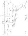
- Figure 7 is a circumferential sectional view through the fuel shield and pilot vane illustrated in Figure 5 and taken along line 7-7.
- Illustrated schematically in Figure 1 is an aircraft turbofan
gas turbine engine 10 configured for powering an aircraft in flight. The engine includes in serial flow communication a row of variable inlet guide vanes (IGVs) 12, multistage fan 14, multistageaxial compressor 16,combustor 18, single stage high pressure turbine (HPT) 20, single stage low pressure turbine (LPT) 22, and arear frame 24 all coaxially disposed along the longitudinal oraxial centerline axis 26. - During operation,
air 28 enters the engine through theIGVs 12 and is pressurized in turn through the fan 14 andcompressor 16. Fuel is injected into the pressurized air in thecombustor 18 and ignited for generatinghot combustion gases 30. - Energy is extracted from the gases in the HPT 20 for powering the
compressor 16 through a drive shaft extending therebetween. Additional energy is extracted from the gases in theLPT 22 for powering the fan 14 through another drive shaft extending therebetween. - An
annular bypass duct 32 surrounds the core engine and bypasses a portion of the pressurized fan air from entering the compressor. The bypass air joins the combustion gases downstream of the LPT which are collectively discharged from the engine for producing propulsion thrust during operation. - The turbofan engine illustrated in Figure 1 also includes an augmentor or
afterburner 34 at the aft end thereof. The afterburner includes anannular flameholder assembly 36 at the upstream end thereof, and anannular afterburner liner 38 extends downstream therefrom. Additional fuel is suitably injected into the flameholder during operation for mixing with the exhaust flow from the turbofan engine and producing additional combustion gases contained within theflameholder liner 38. - A variable area exhaust nozzle (VEN) 40 is disposed at the aft end of the afterburner and includes a row of movable exhaust flaps which are positionable to form a converging-diverging (CD) exhaust nozzle for optimizing performance of the engine during both dry, non-augmented operation and wet, augmented operation of the engine.
- The basic engine illustrated in Figure 1 is conventional in configuration and operation, and as indicated above has experienced many years of successful use throughout the world. The
annular flameholder 36 thereof is also conventional in this engine and is modified as described hereinbelow for improved durability thereof. - The upstream portion of the
afterburner 34 is illustrated in more detail in Figure 2, with Figures 3 and 4 illustrating forward and aft views of the exemplaryannular flameholder assembly 36 thereof. - The flameholder assembly includes a row of flameholder or swirl vanes or
partitions 42 fixedly joined, by brazing for example, to radially outer andinner shells vanes 42 is hollow, as best illustrated in Figure 3, and includes a first orpressure sidewall 48 and a circumferentially opposite second orsuction sidewall 50 extending axially between opposite leading andtrailing edges - The two
sidewalls edge 52 at an included angle of about 90 degrees. Thefirst sidewall 48 is generally concave aft therefrom and is imperforate between the leading and trailing edges. - The
second sidewall 50 is generally convex and is imperforate from the leading edge aft to about the maximum width of the vane. The second sidewall includes a generally flat aft panel that forms circumferentially with the adjoining vanes a substantially flat annular bluff body having flameholder capability as illustrated in part in Figure 4. - The aft panels include a pattern of
radial discharge slots 56 which are fed by anupstream scoop 58 shown in Figure 2 that receives a portion of the un-carbureted exhaust flow from the turbofan engine. Exhaust flow is channeled through thescoop 58 and an inlet aperture in theinner shell 46 to feed the inside of each of the vanes with the exhaust flow. This internal exhaust flow cools the vanes during operation, and is discharged through theexit slots 56 in the aft panels for providing thermal insulation against the hot combustion gases generated downstream in the afterburner during operation. - The row of
vanes 42 thusly defines an outer flameholder, and a cooperating annularinner flameholder 60 is mounted concentrically therein by a plurality of supporting links or bars shown in Figures 3 and 4. And, a radial crossover gutter extends between the aft end of theinner shell 46 and theinner flameholder 60 as illustrated in Figures 2 and 4 to maintain ignition flow communication therebetween. - As shown in Figure 3, a plurality of main fuel injectors or
spraybars 62 are distributed circumferentially in a row before the row offlameholder vanes 42. For example, twomain spraybars 62 are provided for each of thevanes 42 and straddle each vane on circumferentially opposite sides of the leadingedge 52. - A smaller plurality of pilot fuel injectors or
spraybars 64 are positioned before the correspondingleading edges 52 in a one-to-one correspondence with corresponding ones of the flameholder vanes, also referred to aspilot vanes 42. For example, apilot spraybar 64 may be located before the leading edge of everyother vane 42 and therefore have a total number which is half that of the total number ofvanes 42. - As shown in Figures 2 and 3, the outer and
inner shells vanes 42 and downstream from the trailing edges thereof and diverge radially in the downstream aft direction therebetween. The leading edges of the two shells form an annular inlet through which a portion of theengine exhaust 30 is received during operation. - The two shells are jointed together along their leading edges by a row of radially extending tubes. And, the shells have a series of U-shaped slots along the leading edges thereof which receive respective ones of the main and pilot spraybars when assembled.
- As shown in Figures 3 and 5, the
vanes 42 are spaced apart circumferentially and define therebetween flow passages in which the injected fuel mixes with the exhaust flow for providing the fuel and air mixture that is ignited in the afterburner during operation. The inter-vane flow passages initially converge in the axial downstream direction and then may diverge from the maximum width of the vanes to their trailing edges in accordance with conventional practice. - The resulting configuration of the vane passages is therefore a relatively complex 3-D cooperation of the vanes and shells.
- During operation, fuel is suitably channeled through the pilot spraybars 64 and injected in front of the pilot vanes where it mixes with exhaust flow from the turbofan engine and is suitably ignited by an
electrical igniter 66 illustrated in Figure 2 for initiating the afterburner combustion flame. Additional fuel is injected through themain spraybars 62 at different radial locations within the flameholder assembly and adds to the combustion flame which is held by the outer flameholder defined by thevanes 42 and theinner flameholder 60 having the form of an annular V-gutter facing in the downstream direction. - The
afterburner 34 and thebasic flameholder assembly 36 described above are conventional in configuration and operation and are found in the exemplary turbofan engine described above which has experienced many years of successful commercial use throughout the world. - However, the
pilot spraybars 64 described above inject relatively cold fuel against the leadingedge 52 of thepilot vanes 42 during operation which leads to substantial gradients in temperature of the pilot vanes. This temperature gradient then leads to thermal distress over many cycles of operation of the engine. The pilot vanes are thusly limited in life by thermally induced cracks in the leading edge regions thereof through which pilot fuel may enter, ignite, and heat the vanes from inside leading to premature failure of the aft panels. - Accordingly, the conventional flameholder described above is modified as described hereinbelow for protecting the
pilot vanes 42 against the cold quenching affect of the injected pilot fuel for substantially increasing the useful life of the flameholder assembly well beyond that of the conventional flameholder. - The problem of fuel quenching of the leading edge regions of the
pilot vanes 42 is solved by introducing a plurality of identical fuel shields 68 disposed in front of corresponding ones of thepilot vanes 42 behind the correspondingpilot spraybars 64. Each fuel shield is configured to aerodynamically match or complement the leading edge region of each pilot vane and suitably covers this region to prevent direct impingement of the injected fuel thereagainst. - The fuel shields 68 are shown in several views in Figures 2, 3 and 5 and are introduced solely at the
pilot vanes 42 corresponding with the pilot spraybars, and not on the remainder of flameholder vanes which are not subject to fuel quenching along their leading edges. - Figures 5 shows an enlarged isometric view of one of the fuel shields 68 bridging the leading edge of the
pilot vane 42, and Figures 6 and 7 illustrate corresponding radial and circumferential sectional views thereof. These three figures illustrate the aerodynamic configuration of the fuel shields 68 conforming with the 3-D configuration of the leading edge region of thepilot vanes 42 between the outer and inner andshells - The shields are suitably mounted to the
vane 42 between the twoshells gap 70 around the vane leading edge for protecting the leading edge from quenching by the cool pilot fuel when injected. In this way, the leading edge region of each vane behind the fuel shield is then permitted to operate at a higher temperature than previously obtained under fuel quenching, which correspondingly reduces the thermal gradients in this region of the pilot vane, and in turn substantially reduces thermal distress. Accordingly, the useful life of the flameholder assembly may be increased significantly. - The fuel shield illustrated in Figure 5 includes a pair of first and second imperforate thin plates or
wings nose 76 that defines the unsupported or cantilevered forward distal ends thereof. - As shown in Figure 5, a circumferentially extending outer sleeve or
hood 78 is integrally joined to the common radially outer or lateral edges of the twowings common hood 78 extends axially forwardly in the upstream direction obliquely from the two wings and generally perpendicularly thereto. - The
hood 78 is spaced at least in part radially inwardly from theouter shell 44 to form a corresponding forward space orgap 80 therebetween disposed in flow communication with theaft gap 70. - As illustrated in Figures 5-7, the two
wings pilot vane 42 around the leading edge region thereof, while thehood 78 is configured to complement its junction with theouter shell 44. In this way, the forward andaft gaps - The flameholder vanes 42 themselves are made of suitable heat resistant metal for use in the hostile environment of the afterburner, and correspondingly the fuel shields 68 may be made of similar or different heat resistant metal. For example, the fuel shields may be formed from a nickel based superalloy such as Inconel (TM) 625 which is commercially available for use in gas turbine engines.
- The two
wings inner gutter 82 which extends along the full circumferential length of the opposite radially inner lateral edges of the two wings and bridging thecommon nose 76 thereof. Theinner gutter 82 provides a local, circumferentially extending channel with a generally U-shaped radial cross section that provides several advantages in the fuel shield. Thegutter 82 is bent or offset aft from the two wings to form theaft gap 70 between the vane sidewalls and the wings as the gutter contacts or abuts the sidewalls upon assembly. - Correspondingly, the
hood 78 preferably includes a pair of integral lands ortabs 84 at opposite circumferential ends thereof corresponding with the opposite ends of each of the twowings tabs 84 is offset radially outwardly in thickness of the hood toward the outer shell to form theforward gap 80 over most of the surface area of the hood where it underlies the outer shell. - The two
wings integral gutters 82 therein. Correspondingly, thecommon hood 78 may also be formed of substantially flat and thin sheet metal and may remain flat between the twoend tabs 84, or may be suitably arcuate to conform with the arcuate configuration of the surrounding outer shell. The twoend tabs 84 may be readily bent or fabricated into the sheet metal construction of thehood 78. - Figures 5-7 illustrate the corresponding flowpath thusly created behind the fuel shield when it is suitably mounted in front of the
pilot vane 42. Thenose 76 of the shield is aligned with thevane leading edge 52, and the twowings second sidewalls - The
common hood 78 extends axially upstream below the outer shell to form theforward gap 80 therebetween which provides an upstream inlet that receives a portion of theexhaust flow 30 from the turbofan engine. Theexhaust flow 30 is thusly channeled downstream through theforward gap 80 and then continues radially inwardly into theaft gap 70 between the wings and pilot vane. Theexhaust flow 30 thusly continuously purges the backside of the fuel shield between the outer shell and pilot vane and increases the temperature of the leading edge region of the pilot vane. - The
pilot spraybar 64 is mounted in front of the fuel shield, which shield thusly protects the leading edge region of each pilot vane from direct contact with the injected pilot fuel over the corresponding area thereof. The leading edge region of the pilot vane is thusly protected from quenching by the injected pilot fuel and will operate at a higher temperature without quenching thereof for thereby reducing the thermal gradients with the remainder of the pilot vane. Furthermore, the hot purge flow channeled between the wings and the pilot vane directly heats the pilot vane to further promote the reduction in temperature gradients therein during operation. - Since the
pilot vane 42 initially diverges in the downstream direction on both sides of the leadingedge 52, the corresponding fuel shields 68 similarly diverge to complement the 3-D configuration of the vane. As shown in Figure 7, the two wings of the fuel shield are oblique with each other with an included angle therebetween of about 90 degrees, and conform generally with the corresponding configuration of the vane around its leadingedge 52. - Figures 5-7 illustrate that the two
tabs 84 preferably terminate in thehood 78 axially short of the correspondingwings forward gap 80 axially between the aft ends of the two tabs and the junction of the hood with the two wings. - In this way, the inlet purge flow through the
forward gap 80 is channeled initially axially aft over the hood and then flows both radially inwardly into theaft gap 70, as well as circumferentially outwardly over both wings behind the correspondingtabs 84. - Since the
inner gutter 82 extends along the full circumferential length of the two wings and preferably abuts the corresponding sidewalls of the pilot vane, the purge flow behind the two wings is discharged therefrom circumferentially outwardly along the corresponding downstream or aft ends of the two wings. - The purge flow not only purges the
aft gap 70 during operation, but heats the leading edge region of the pilot vane, and also provides a flow barrier when discharged from the shield to protect the downstream portions of the vane from the pilot fuel injected at the nose of the fuel shield. - The
fuel shield 68 illustrated in Figure 5 is preferably fixedly joined to theouter shell 44 at the twohood tabs 84 by corresponding welds orbrazes 86, or both, as indicated schematically by the local X's. The fuel shield is also preferably fixedly joined to the twovane sidewalls inner gutter 82 by corresponding welds orbrazes 86, or both as desired. - In this way, the thin, sheet metal wings and hood are fixedly joined at the corresponding four corners thereof to the outer shell and pilot vane to provide a rigid connection which also permits relatively unrestrained expansion and contraction of the fuel shield which is otherwise unrestrained along the majority of its inboard surface area.
- The two
brazes 86 at the opposite forward ends of thehood 78 securely mount the hood to the outer shell for withstanding the aerodynamic pressure forces of theincoming exhaust flow 30. Similarly, the twoend brazes 86 at the opposite corners of the two wings maintain theinner gutter 82 in abutment with the vane sidewalls against the aerodynamic pressure forces of the purge flow being channeled through theaft gap 70. - Figures 5-7 also illustrate the location of the
pilot spraybar 64 suitably upstream from the leadingedge 52 of the pilot vane. Thehood 78 extends suitably upstream from the two wings and pilot vane to prevent ingestion of the fuel into the space behind the fuel shield and in turn prevent combustion in this region. - Accordingly, the
hood 78 preferably includes anaccess slot 88 disposed laterally in the circumferential middle or center between theopposite end tabs 84 for receiving the pilot spraybar and permitting the hood to extend axially upstream therefrom. - The
hood 78 preferably also includes a radially outwardly extending barrier clip orfence 90 integrally joined by welding or brazing to the hood along the full perimeter of theaccess slot 88. Theslot 88 is generally U-shaped with its open end facing in the upstream forward direction. The fence may be formed of sheet metal and extends obliquely or generally perpendicularly and radially outwardly from the outer surface of the hood. - The radial height of the
fence 90 illustrated in Figures 5 and 6 corresponds with the radial height of theforward gap 80 and provides an effective flow barrier between the hood and corresponding slot in theouter shell 44 to prevent flow communication of the injected pilot fuel into theforward gap 80. - The
central slot 88 and sealingfence 90 bifurcate thehood 78 circumferentially and thusly define two corresponding inlets into thecommon forward gap 80. The aft end of theslot 88 is spaced forwardly from the vane leading edge and closely adjacent to thepilot spraybar 64 disposed in the slot. In this way, the forward and aft gaps defined behind the fuel shield provide an independent flowpath for channeling the purge exhaust flow therethrough without opportunity for undesirable ingestion of the pilot fuel injected from the pilot spraybar during operation. - Both the hood and two wings correspondingly conform with the outer shell and pilot vane to maintain the aerodynamic configurations thereof and minimize any aerodynamic disturbance in the exhaust flow as it flows through the flameholder. Correspondingly, the fuel shield minimizes any disturbance in the operation of the
pilot spraybar 64 which injects the pilot fuel along bothsidewalls wings - The
inner gutter 82 illustrated in Figures 5 and 6 has a generally U-shaped cross section for offsetting the two wings from the vane sidewalls to maintain the depth of thecorresponding aft gap 70, and preferably terminates in a radially inner, free edge or lip that extends forwardly in the axial upstream direction of thehood 78. - The
inner gutter 82 is preferably spaced above theinner shell 46 as illustrated in Figure 6 to provide a suitable spacing between the inner lip of the gutter and theinner shell 46 to provide additional advantage. Firstly, the so truncatedinner gutter 82 only partly covers the junction of the inner bullnose of thepilot vane 42 with theinner shell 46 and permits visual inspection of the braze joint therebetween during the manufacturing process. - Furthermore, the so truncated
inner gutter 82 also provides a suspended lip or edge along which the injected pilot fuel undergoes slinging or shearing when mixing with the high velocity incoming exhaust flow leading to enhanced vaporization thereof. In this way, theinner gutter 82 enhances mixing of the injected pilot fuel with theexhaust flow 30 while protecting theinner shell 46 therefrom. - During operation, both the
incoming exhaust flow 30 and the injected pilot fuel flow downstream over the twowings inner shell 46. - Correspondingly, the
hood 78 protects theouter shell 44 from the injected pilot fuel. Thehood 78 preferably joins the twowings fillet 92 which is spaced from the junction of the vane and outer shell to provide unobstructed flow communication from theforward gap 80 around the backside of thefillet 92 to theaft gap 70. The entire fuel shield is therefore spaced over most of its surface area from the pilot vane and the outer shell by theinner gutter 82 at the radially inner end thereof and by the twoend tabs 84 at the radially outer end thereof. - The resulting backside flowpath formed behind the fuel shield provides axial inlets in the
forward gap 80 for receiving thepurge flow 30 which is then smoothly guided both radially inwardly through theaft gap 70 as well as guided circumferentially or laterally outwardly from both aft ends of the two correspondingwings 74, as well as from the aft portions of theforward gap 80 provided directly behind the twotabs 84. - Accordingly, the thin, sheet metal configuration of the
fuel shield 68 can be introduced in the flameholder with a minimal change in the 3-D configuration thereof, while maintaining the desired aerodynamic performance of the flameholder, while also protecting the pilot vanes from the injected pilot fuel, with corresponding purge flow efficiently provided behind the fuel shield. - The fuel shield illustrated in Figures 5 and 7 is preferably formed by metal fabrication from sheet metal, or could be formed by the more expensive process of casting if desired. In the preferred sheet metal construction, the
first wing 72 and the corresponding half portion of thehood 78 may comprise a unitary piece of sheet metal suitably bent to shape to additionally include the correspondinginner gutter 82 and offsettab 84. - Similarly, the
second wing 74 and corresponding opposite half portion of thehood 78 may comprise another unitary piece of sheet metal similarly bent to shape in a generally symmetrical or mirror-image counterpart of the corresponding half of the shield. - The two sheets or pieces may then be suitably joined together along the middle or centerline which defines the
common nose 76, and along the two symmetrical halves of theslot 88. Welding or brazing may be used to join these two pieces together. - The
fence 90 is preferably a third unitary piece which may be readily welded or brazed to the prejoined halves of the fuel shield in an integral three-piece assembly thereof. - As shown in Figure 5, the exposed external surface of the
fuel shield 68 may be suitably covered with a conventional ceramic-based thermal barrier coating (TBC) 94, which is also applied to the exposed surfaces of the flameholder vanes and shells in conventional practice. - Thermal barrier coatings are conventional in modern gas turbine engines. The
TBC 94 is a thermally insulating ceramic material sprayed on metal components during the manufacturing process. The entire external surfaces of the flameholder vanes and fuel shields shown in Figure 5 for example, are suitably covered with the TBC to enhance their useful life. - The fuel shield disclosed above in its simple sheet metal configuration may be readily and inexpensively manufactured and introduced into new or existing flameholders with little modification thereof and without adversely affecting aerodynamic performance thereof. And, the fuel shield protects the pilot vanes from the quenching affect of the injected pilot fuel for substantially reducing the thermal gradients in the pilot vanes and increasing their useful life.
- Since the fuel shield itself is an independent component selectively mounted at the limited braze joints 86, it remains relatively thermally free and unrestrained and experiences limited thermal gradients therein for a correspondingly long useful life thereof.
- Not only are the pilot vanes themselves protected from pilot fuel quenching, but the purge flowpath provided behind the fuel shield and the pilot vanes permits the exhaust flow to heat the pilot vanes themselves for reducing the thermal gradients therein, while also purging the shield-vane flow passage of any pilot fuel which may migrate therein.
- The purge flow also heats the backside of the fuel shield itself which increases it minimum operating temperature and correspondingly reduces thermal gradients in the shield itself and the corresponding thermal stresses.
- The pilot spraybar continues to operate in its intended manner with the incoming exhaust flow in front of each pilot vane. The fuel shield conforms with the original 3-D configuration of the flameholder in the vicinity of the pilot spraybar, and introduces the auxiliary purge flowpath behind the hood and cooperating two wings of the shield. The purge flow is discharged from the fuel shield between the outlet gaps at the opposite ends of the two wings and the aft end of the hood behind the two
tabs 84 to promote mixing of the pilot fuel downstream therefrom. Theinner gutter 82 provides an additional mechanism along which the injected pilot fuel may undergo shearing for enhanced mixing and vaporization in the exhaust flowstream. - The gutter lip enhances shedding and mixing of liquid pilot fuel to promote quicker mixing thereof with the exhaust flow for promoting combustion ignition and lightoff and combustion stability. And, the spaced inner gutter prevents pilot fuel from engaging the inner shell and prevents spontaneous combustion thereof.
- While there have been described herein what are considered to be preferred and exemplary embodiments of the present invention, other modifications of the invention shall be apparent to those skilled in the art from the teachings herein, and it is, therefore, desired to be secured in the appended claims all such modifications as fall within the true spirit and scope of the invention.
-
- 10
- gas turbine engine
- 12
- inlet guide vanes (IGVs)
- 14
- fan
- 16
- compressor
- 18
- combustor
- 20
- high pressure turbine (HPT)
- 22
- low pressure turbine (LPT)
- 24
- rear frame
- 26
- centerline axis
- 28
- air
- 30
- combustion gases
- 32
- bypass duct
- 34
- afterburner
- 36
- flameholder assembly
- 38
- flameholder liner
- 40
- variable area exhaust nozzle (VEN)
- 42
- vanes
- 44
- outer shell
- 46
- inner shell
- 48
- pressure sidewall
- 50
- suction sidewall
- 52
- leading edge
- 54
- trailing edge
- 56
- discharge slots
- 58
- scoop
- 60
- inner flameholder
- 62
- main spraybars
- 64
- pilot spraybars
- 66
- igniter
- 68
- fuel shield
- 70
- aft gap
- 72
- first wing
- 74
- second wing
- 76
- nose
- 78
- hood
- 80
- forward gap
- 82
- inner gutter
- 84
- tabs
- 86
- brazes
- 88
- access slot
- 90
- fence
- 92
- fillet
- 94
- thermal barrier coating (TBC)
Claims (10)
- An afterburner (34) for a turbofan engine (10) comprising:a row of flameholder vanes (42) joined to radially outer and inner shells (44,46);each of said vanes (42) including first and second sidewalls (48,50) extending between leading and trailing edges (52,54);a plurality of main fuel spraybars (62) distributed circumferentially before said vanes (42);a smaller plurality of pilot fuel spraybars (64) positioned before leading edges (52) of corresponding pilot vanes (42); anda plurality of fuel shields disposed between corresponding pilot vanes (42) and said pilot spraybars (64), and covering said leading edges (52) of said pilot vanes with a thermally insulating aft gap (70) therebetween, and each fuel shield (68) is spaced from said outer shell (44) to form a forward gap (80) therebetween disposed in flow communication with said aft gap (70).
- An afterburner according to claim 1 wherein each of said fuel shields (68) comprises:first and second wings (72,74) obliquely joined together at a nose (76) aligned with said vane leading edge (52);a hood (78) integrally joined to a common radially outer edge of said wings (72,74) and extending axially forwardly therefrom; andsaid wings (72,74) being configured to complement said flameholder vane (42) around said leading edge (52) to effect said aft gap (70), and said hood (78) being configured to complement said outer shell (44) to effect said forward gap (80) radially therebetween.
- An afterburner according to claim 2 wherein said wings (72,74) include a radially inner gutter (82) extending along an opposite radially inner edge thereof and abutting said pilot vane, and offset aft from said wings to form said aft gap (70) with said vane sidewalls (48,50).
- An afterburner according to claim 2 or claim 3 wherein said hood (78) includes a pair of tabs (84) at opposite circumferential ends thereof corresponding with each of said wings (72,74), and each of said tabs (84) is offset radially outwardly from said hood (78) and abuts said outer shell (44) to form said forward gap (80) with said outer shell (44).
- An afterburner according to any one of claims 2 to 4 wherein said tabs (84) terminate in said hood (78) axially short of said wings (72,74) to continue said forward gap (80) axially therebetween.
- An afterburner according to any one of claims 2 to 5 wherein said hood (78) further includes an access slot (88) disposed laterally between said opposite tabs (84), and a corresponding pilot spraybar (64) is disposed in said slot (88).
- An afterburner according to any one of claims 2 to 6 wherein said hood (78) further includes a fence (90) integrally joined thereto along said access slot (88) and extending radially outwardly therefrom to join said outer shell (44).
- An afterburner according to any one of claims 2 to 7 wherein said inner gutter (82) terminates in a lip extending forwardly with said hood (78).
- An afterburner according to any one claims 2 to 8 wherein said hood (78) joins said wings (72,74) at a common fillet (92) therebetween to provide flow communication from said forward gap (80), around said fillet (92), to said aft gap (70).
- An afterburner according to any one of claims 2 to 9 wherein said first wing (72) and corresponding portion of said hood (78) comprises a unitary piece of sheet metal, and said second wing (74) and corresponding portion of said hood (78) comprise another uniform piece of sheet metal, and said two sheets are joined together along the middle of said fuel shield.
Applications Claiming Priority (1)
| Application Number | Priority Date | Filing Date | Title |
|---|---|---|---|
| US11/478,246 US7581398B2 (en) | 2006-06-29 | 2006-06-29 | Purged flameholder fuel shield |
Publications (3)
| Publication Number | Publication Date |
|---|---|
| EP1873387A2 true EP1873387A2 (en) | 2008-01-02 |
| EP1873387A3 EP1873387A3 (en) | 2012-03-14 |
| EP1873387B1 EP1873387B1 (en) | 2013-07-03 |
Family
ID=38565511
Family Applications (1)
| Application Number | Title | Priority Date | Filing Date |
|---|---|---|---|
| EP07106768.0A Not-in-force EP1873387B1 (en) | 2006-06-29 | 2007-04-24 | Purged flameholder fuel shield |
Country Status (5)
| Country | Link |
|---|---|
| US (1) | US7581398B2 (en) |
| EP (1) | EP1873387B1 (en) |
| KR (1) | KR101378179B1 (en) |
| AU (1) | AU2007201868B2 (en) |
| CA (1) | CA2586431C (en) |
Cited By (2)
| Publication number | Priority date | Publication date | Assignee | Title |
|---|---|---|---|---|
| EP2969740B1 (en) * | 2013-03-15 | 2020-05-06 | President and Fellows of Harvard College | Void structures with repeating elongated-aperture pattern |
| FR3136017A1 (en) * | 2022-05-30 | 2023-12-01 | Safran Aircraft Engines | FLAME HOLDER RING FOR TURBORE ENGINE AFTERCOMBUSTION INCLUDING PRIMARY FLOW SAMPLING SCOPES |
Families Citing this family (6)
| Publication number | Priority date | Publication date | Assignee | Title |
|---|---|---|---|---|
| US7565804B1 (en) * | 2006-06-29 | 2009-07-28 | General Electric Company | Flameholder fuel shield |
| FR2942640B1 (en) * | 2009-03-02 | 2011-05-06 | Snecma | POST-COMBUSTION CHAMBER FOR TURBOMACHINE |
| US9709274B2 (en) * | 2013-03-15 | 2017-07-18 | Rolls-Royce Plc | Auxetic structure with stress-relief features |
| US10337341B2 (en) | 2016-08-01 | 2019-07-02 | United Technologies Corporation | Additively manufactured augmentor vane of a gas turbine engine with additively manufactured fuel line extending therethrough |
| US10436447B2 (en) | 2016-08-01 | 2019-10-08 | United Technologies Corporation | Augmentor vane assembly of a gas turbine engine with an additively manufactured augmentor vane |
| RU205518U1 (en) * | 2021-03-10 | 2021-07-19 | Акционерное общество "ОДК-Климов" | TWO-CIRCUIT TURBOJET ENGINE INJECTOR CHAMBER |
Citations (3)
| Publication number | Priority date | Publication date | Assignee | Title |
|---|---|---|---|---|
| US3765178A (en) * | 1972-09-08 | 1973-10-16 | Gen Electric | Afterburner flameholder |
| US3800527A (en) * | 1971-03-18 | 1974-04-02 | United Aircraft Corp | Piloted flameholder construction |
| US3931707A (en) * | 1975-01-08 | 1976-01-13 | General Electric Company | Augmentor flameholding apparatus |
Family Cites Families (24)
| Publication number | Priority date | Publication date | Assignee | Title |
|---|---|---|---|---|
| US3054259A (en) | 1962-09-18 | Combustion apparatus | ||
| US2693083A (en) | 1951-03-26 | 1954-11-02 | Roy W Abbott | Combination flame-holder and fuel nozzle |
| US2872785A (en) | 1951-06-06 | 1959-02-10 | Curtiss Wright Corp | Jet engine burner apparatus having means for spreading the pilot flame |
| US2780916A (en) | 1952-08-22 | 1957-02-12 | Continental Aviat & Engineerin | Pilot burner for jet engines |
| US2780061A (en) | 1953-05-08 | 1957-02-05 | Lucas Industries Ltd | Liquid fuel burner for a combustion chamber provided with a surrounding air jacket |
| US2799991A (en) * | 1954-03-05 | 1957-07-23 | Earl W Conrad | Afterburner flame stabilization means |
| US2861424A (en) | 1954-04-09 | 1958-11-25 | Douglas Aircraft Co Inc | Fuel supply means for combustion apparatus |
| US2920445A (en) | 1957-01-15 | 1960-01-12 | Curtiss Wright Corp | Flame holder apparatus |
| US3176465A (en) | 1962-08-27 | 1965-04-06 | Gen Electric | Vapor fuel injector flameholder |
| US4064691A (en) | 1975-11-04 | 1977-12-27 | General Electric Company | Cooling of fastener means for a removable flameholder |
| US4312185A (en) | 1980-02-19 | 1982-01-26 | General Electric Company | Low profile fuel injection system |
| US4445339A (en) | 1980-11-24 | 1984-05-01 | General Electric Co. | Wingtip vortex flame stabilizer for gas turbine combustor flame holder |
| US4490973A (en) | 1983-04-12 | 1985-01-01 | The United States Of America As Represented By The Secretary Of The Air Force | Flameholder with integrated air mixer |
| US4813229A (en) | 1985-03-04 | 1989-03-21 | General Electric Company | Method for controlling augmentor liner coolant flow pressure in a mixed flow, variable cycle gas |
| US4989407A (en) | 1986-08-29 | 1991-02-05 | United Technologies Corporation | Thrust augmentor flameholder |
| US5001898A (en) | 1986-08-29 | 1991-03-26 | United Technologies Corporation | Fuel distributor/flameholder for a duct burner |
| US5020318A (en) | 1987-11-05 | 1991-06-04 | General Electric Company | Aircraft engine frame construction |
| US5076062A (en) | 1987-11-05 | 1991-12-31 | General Electric Company | Gas-cooled flameholder assembly |
| US4887425A (en) | 1988-03-18 | 1989-12-19 | General Electric Company | Fuel spraybar |
| US5142858A (en) | 1990-11-21 | 1992-09-01 | General Electric Company | Compact flameholder type combustor which is staged to reduce emissions |
| US5396763A (en) * | 1994-04-25 | 1995-03-14 | General Electric Company | Cooled spraybar and flameholder assembly including a perforated hollow inner air baffle for impingement cooling an outer heat shield |
| US5813221A (en) | 1997-01-14 | 1998-09-29 | General Electric Company | Augmenter with integrated fueling and cooling |
| FR2770284B1 (en) * | 1997-10-23 | 1999-11-19 | Snecma | CARBIDE AND OPTIMIZED COOLING FLAME HANGER |
| ATE233393T1 (en) | 1997-12-08 | 2003-03-15 | Volvo Aero Corp | FLAME HOLDER FOR GAS TURBINE AFTERBURNERS |
-
2006
- 2006-06-29 US US11/478,246 patent/US7581398B2/en active Active
-
2007
- 2007-04-24 EP EP07106768.0A patent/EP1873387B1/en not_active Not-in-force
- 2007-04-26 CA CA2586431A patent/CA2586431C/en not_active Expired - Fee Related
- 2007-04-27 AU AU2007201868A patent/AU2007201868B2/en not_active Ceased
- 2007-04-27 KR KR1020070041360A patent/KR101378179B1/en active IP Right Grant
Patent Citations (3)
| Publication number | Priority date | Publication date | Assignee | Title |
|---|---|---|---|---|
| US3800527A (en) * | 1971-03-18 | 1974-04-02 | United Aircraft Corp | Piloted flameholder construction |
| US3765178A (en) * | 1972-09-08 | 1973-10-16 | Gen Electric | Afterburner flameholder |
| US3931707A (en) * | 1975-01-08 | 1976-01-13 | General Electric Company | Augmentor flameholding apparatus |
Cited By (3)
| Publication number | Priority date | Publication date | Assignee | Title |
|---|---|---|---|---|
| EP2969740B1 (en) * | 2013-03-15 | 2020-05-06 | President and Fellows of Harvard College | Void structures with repeating elongated-aperture pattern |
| US10823409B2 (en) | 2013-03-15 | 2020-11-03 | President And Fellows Of Harvard College | Void structures with repeating elongated-aperture pattern |
| FR3136017A1 (en) * | 2022-05-30 | 2023-12-01 | Safran Aircraft Engines | FLAME HOLDER RING FOR TURBORE ENGINE AFTERCOMBUSTION INCLUDING PRIMARY FLOW SAMPLING SCOPES |
Also Published As
| Publication number | Publication date |
|---|---|
| EP1873387B1 (en) | 2013-07-03 |
| KR20080001605A (en) | 2008-01-03 |
| AU2007201868B2 (en) | 2012-03-22 |
| US7581398B2 (en) | 2009-09-01 |
| EP1873387A3 (en) | 2012-03-14 |
| CA2586431A1 (en) | 2007-12-29 |
| KR101378179B1 (en) | 2014-03-25 |
| AU2007201868A1 (en) | 2008-01-17 |
| CA2586431C (en) | 2013-11-12 |
| US20090113894A1 (en) | 2009-05-07 |
Similar Documents
| Publication | Publication Date | Title |
|---|---|---|
| EP1873387B1 (en) | Purged flameholder fuel shield | |
| EP1605207B1 (en) | Thrust augmentor for gas turbine engines | |
| US5396761A (en) | Gas turbine engine ignition flameholder with internal impingement cooling | |
| US10041676B2 (en) | Sealed conical-flat dome for flight engine combustors | |
| EP3366996B1 (en) | Combustor liner panel end rails forming an angled cooling interface passage for a gas turbine engine combustor | |
| JP4156245B2 (en) | Slot-cooled combustor liner | |
| EP1010944B1 (en) | Cooling and connecting device for a liner of a gas turbine engine combustor | |
| EP0315485B1 (en) | Gas-cooled flameholder assembly | |
| EP1873459B1 (en) | Flameholder fuel-shield | |
| EP1253379B1 (en) | Methods and apparatus for cooling gas turbine engine combustors | |
| EP2959136B1 (en) | Gas turbine engine combustor provided with finned ignitor grommet | |
| EP3066321B1 (en) | Cooled fuel injector system for a gas turbine engine and method thereof | |
| EP3047127B1 (en) | Angled combustor liner cooling holes through transverse structure within a gas turbine engine combustor | |
| EP3026343B1 (en) | Self-cooled orifice structure | |
| EP2754962A2 (en) | Combustors with hybrid walled liners | |
| EP3039343B1 (en) | Dual fuel nozzle with swirling axial gas injection for a gas turbine engine and related method | |
| EP3361158B1 (en) | Combustor for a gas turbine engine | |
| EP3066390B1 (en) | Gas turbine engine wall assembly with offset rail | |
| EP2230456A2 (en) | Combustion liner with mixing hole stub | |
| EP3220049B1 (en) | Gas turbine combustor having liner cooling guide vanes | |
| US10830433B2 (en) | Axial non-linear interface for combustor liner panels in a gas turbine combustor | |
| EP3321585B1 (en) | Non-planar combustor liner panel for a gas turbine engine combustor | |
| KR100269071B1 (en) | One-piece flame holder |
Legal Events
| Date | Code | Title | Description |
|---|---|---|---|
| PUAI | Public reference made under article 153(3) epc to a published international application that has entered the european phase |
Free format text: ORIGINAL CODE: 0009012 |
|
| AK | Designated contracting states |
Kind code of ref document: A2 Designated state(s): AT BE BG CH CY CZ DE DK EE ES FI FR GB GR HU IE IS IT LI LT LU LV MC MT NL PL PT RO SE SI SK TR |
|
| AX | Request for extension of the european patent |
Extension state: AL BA HR MK YU |
|
| PUAL | Search report despatched |
Free format text: ORIGINAL CODE: 0009013 |
|
| AK | Designated contracting states |
Kind code of ref document: A3 Designated state(s): AT BE BG CH CY CZ DE DK EE ES FI FR GB GR HU IE IS IT LI LT LU LV MC MT NL PL PT RO SE SI SK TR |
|
| AX | Request for extension of the european patent |
Extension state: AL BA HR MK RS |
|
| RIC1 | Information provided on ipc code assigned before grant |
Ipc: F02K 3/10 20060101ALI20120207BHEP Ipc: F02K 1/12 20060101AFI20120207BHEP Ipc: F23R 3/20 20060101ALN20120207BHEP |
|
| 17P | Request for examination filed |
Effective date: 20120914 |
|
| GRAP | Despatch of communication of intention to grant a patent |
Free format text: ORIGINAL CODE: EPIDOSNIGR1 |
|
| RIC1 | Information provided on ipc code assigned before grant |
Ipc: F02K 3/10 20060101ALI20121005BHEP Ipc: F02K 1/12 20060101AFI20121005BHEP Ipc: F23R 3/20 20060101ALN20121005BHEP |
|
| AKX | Designation fees paid |
Designated state(s): AT BE BG CH CY CZ DE DK EE ES FI FR GB GR HU IE IS IT LI LT LU LV MC MT NL PL PT RO SE SI SK TR |
|
| GRAP | Despatch of communication of intention to grant a patent |
Free format text: ORIGINAL CODE: EPIDOSNIGR1 |
|
| RIC1 | Information provided on ipc code assigned before grant |
Ipc: F02K 1/12 20060101AFI20130116BHEP Ipc: F02K 3/10 20060101ALI20130116BHEP Ipc: F23R 3/20 20060101ALN20130116BHEP |
|
| GRAS | Grant fee paid |
Free format text: ORIGINAL CODE: EPIDOSNIGR3 |
|
| GRAA | (expected) grant |
Free format text: ORIGINAL CODE: 0009210 |
|
| AK | Designated contracting states |
Kind code of ref document: B1 Designated state(s): AT BE BG CH CY CZ DE DK EE ES FI FR GB GR HU IE IS IT LI LT LU LV MC MT NL PL PT RO SE SI SK TR |
|
| REG | Reference to a national code |
Ref country code: GB Ref legal event code: FG4D |
|
| REG | Reference to a national code |
Ref country code: CH Ref legal event code: EP Ref country code: AT Ref legal event code: REF Ref document number: 619933 Country of ref document: AT Kind code of ref document: T Effective date: 20130715 |
|
| REG | Reference to a national code |
Ref country code: IE Ref legal event code: FG4D |
|
| REG | Reference to a national code |
Ref country code: DE Ref legal event code: R096 Ref document number: 602007031355 Country of ref document: DE Effective date: 20130829 |
|
| REG | Reference to a national code |
Ref country code: SE Ref legal event code: TRGR |
|
| PG25 | Lapsed in a contracting state [announced via postgrant information from national office to epo] |
Ref country code: SI Free format text: LAPSE BECAUSE OF FAILURE TO SUBMIT A TRANSLATION OF THE DESCRIPTION OR TO PAY THE FEE WITHIN THE PRESCRIBED TIME-LIMIT Effective date: 20130703 |
|
| REG | Reference to a national code |
Ref country code: AT Ref legal event code: MK05 Ref document number: 619933 Country of ref document: AT Kind code of ref document: T Effective date: 20130703 |
|
| REG | Reference to a national code |
Ref country code: NL Ref legal event code: VDEP Effective date: 20130703 |
|
| REG | Reference to a national code |
Ref country code: LT Ref legal event code: MG4D |
|
| PG25 | Lapsed in a contracting state [announced via postgrant information from national office to epo] |
Ref country code: AT Free format text: LAPSE BECAUSE OF FAILURE TO SUBMIT A TRANSLATION OF THE DESCRIPTION OR TO PAY THE FEE WITHIN THE PRESCRIBED TIME-LIMIT Effective date: 20130703 Ref country code: IS Free format text: LAPSE BECAUSE OF FAILURE TO SUBMIT A TRANSLATION OF THE DESCRIPTION OR TO PAY THE FEE WITHIN THE PRESCRIBED TIME-LIMIT Effective date: 20131103 Ref country code: CY Free format text: LAPSE BECAUSE OF FAILURE TO SUBMIT A TRANSLATION OF THE DESCRIPTION OR TO PAY THE FEE WITHIN THE PRESCRIBED TIME-LIMIT Effective date: 20130703 Ref country code: BE Free format text: LAPSE BECAUSE OF FAILURE TO SUBMIT A TRANSLATION OF THE DESCRIPTION OR TO PAY THE FEE WITHIN THE PRESCRIBED TIME-LIMIT Effective date: 20130703 Ref country code: PT Free format text: LAPSE BECAUSE OF FAILURE TO SUBMIT A TRANSLATION OF THE DESCRIPTION OR TO PAY THE FEE WITHIN THE PRESCRIBED TIME-LIMIT Effective date: 20131104 Ref country code: LT Free format text: LAPSE BECAUSE OF FAILURE TO SUBMIT A TRANSLATION OF THE DESCRIPTION OR TO PAY THE FEE WITHIN THE PRESCRIBED TIME-LIMIT Effective date: 20130703 |
|
| PG25 | Lapsed in a contracting state [announced via postgrant information from national office to epo] |
Ref country code: NL Free format text: LAPSE BECAUSE OF FAILURE TO SUBMIT A TRANSLATION OF THE DESCRIPTION OR TO PAY THE FEE WITHIN THE PRESCRIBED TIME-LIMIT Effective date: 20130703 Ref country code: PL Free format text: LAPSE BECAUSE OF FAILURE TO SUBMIT A TRANSLATION OF THE DESCRIPTION OR TO PAY THE FEE WITHIN THE PRESCRIBED TIME-LIMIT Effective date: 20130703 Ref country code: ES Free format text: LAPSE BECAUSE OF FAILURE TO SUBMIT A TRANSLATION OF THE DESCRIPTION OR TO PAY THE FEE WITHIN THE PRESCRIBED TIME-LIMIT Effective date: 20131014 Ref country code: LV Free format text: LAPSE BECAUSE OF FAILURE TO SUBMIT A TRANSLATION OF THE DESCRIPTION OR TO PAY THE FEE WITHIN THE PRESCRIBED TIME-LIMIT Effective date: 20130703 Ref country code: FI Free format text: LAPSE BECAUSE OF FAILURE TO SUBMIT A TRANSLATION OF THE DESCRIPTION OR TO PAY THE FEE WITHIN THE PRESCRIBED TIME-LIMIT Effective date: 20130703 Ref country code: GR Free format text: LAPSE BECAUSE OF FAILURE TO SUBMIT A TRANSLATION OF THE DESCRIPTION OR TO PAY THE FEE WITHIN THE PRESCRIBED TIME-LIMIT Effective date: 20131004 |
|
| PG25 | Lapsed in a contracting state [announced via postgrant information from national office to epo] |
Ref country code: EE Free format text: LAPSE BECAUSE OF FAILURE TO SUBMIT A TRANSLATION OF THE DESCRIPTION OR TO PAY THE FEE WITHIN THE PRESCRIBED TIME-LIMIT Effective date: 20130703 Ref country code: DK Free format text: LAPSE BECAUSE OF FAILURE TO SUBMIT A TRANSLATION OF THE DESCRIPTION OR TO PAY THE FEE WITHIN THE PRESCRIBED TIME-LIMIT Effective date: 20130703 Ref country code: CZ Free format text: LAPSE BECAUSE OF FAILURE TO SUBMIT A TRANSLATION OF THE DESCRIPTION OR TO PAY THE FEE WITHIN THE PRESCRIBED TIME-LIMIT Effective date: 20130703 Ref country code: SK Free format text: LAPSE BECAUSE OF FAILURE TO SUBMIT A TRANSLATION OF THE DESCRIPTION OR TO PAY THE FEE WITHIN THE PRESCRIBED TIME-LIMIT Effective date: 20130703 Ref country code: RO Free format text: LAPSE BECAUSE OF FAILURE TO SUBMIT A TRANSLATION OF THE DESCRIPTION OR TO PAY THE FEE WITHIN THE PRESCRIBED TIME-LIMIT Effective date: 20130703 |
|
| PLBE | No opposition filed within time limit |
Free format text: ORIGINAL CODE: 0009261 |
|
| STAA | Information on the status of an ep patent application or granted ep patent |
Free format text: STATUS: NO OPPOSITION FILED WITHIN TIME LIMIT |
|
| 26N | No opposition filed |
Effective date: 20140404 |
|
| REG | Reference to a national code |
Ref country code: DE Ref legal event code: R097 Ref document number: 602007031355 Country of ref document: DE Effective date: 20140404 |
|
| PG25 | Lapsed in a contracting state [announced via postgrant information from national office to epo] |
Ref country code: LU Free format text: LAPSE BECAUSE OF FAILURE TO SUBMIT A TRANSLATION OF THE DESCRIPTION OR TO PAY THE FEE WITHIN THE PRESCRIBED TIME-LIMIT Effective date: 20140424 Ref country code: MC Free format text: LAPSE BECAUSE OF FAILURE TO SUBMIT A TRANSLATION OF THE DESCRIPTION OR TO PAY THE FEE WITHIN THE PRESCRIBED TIME-LIMIT Effective date: 20130703 |
|
| REG | Reference to a national code |
Ref country code: CH Ref legal event code: PL |
|
| REG | Reference to a national code |
Ref country code: IE Ref legal event code: MM4A |
|
| PG25 | Lapsed in a contracting state [announced via postgrant information from national office to epo] |
Ref country code: LI Free format text: LAPSE BECAUSE OF NON-PAYMENT OF DUE FEES Effective date: 20140430 Ref country code: CH Free format text: LAPSE BECAUSE OF NON-PAYMENT OF DUE FEES Effective date: 20140430 |
|
| PG25 | Lapsed in a contracting state [announced via postgrant information from national office to epo] |
Ref country code: IE Free format text: LAPSE BECAUSE OF NON-PAYMENT OF DUE FEES Effective date: 20140424 |
|
| PG25 | Lapsed in a contracting state [announced via postgrant information from national office to epo] |
Ref country code: MT Free format text: LAPSE BECAUSE OF FAILURE TO SUBMIT A TRANSLATION OF THE DESCRIPTION OR TO PAY THE FEE WITHIN THE PRESCRIBED TIME-LIMIT Effective date: 20130703 |
|
| REG | Reference to a national code |
Ref country code: FR Ref legal event code: PLFP Year of fee payment: 10 |
|
| PG25 | Lapsed in a contracting state [announced via postgrant information from national office to epo] |
Ref country code: BG Free format text: LAPSE BECAUSE OF FAILURE TO SUBMIT A TRANSLATION OF THE DESCRIPTION OR TO PAY THE FEE WITHIN THE PRESCRIBED TIME-LIMIT Effective date: 20130703 |
|
| PG25 | Lapsed in a contracting state [announced via postgrant information from national office to epo] |
Ref country code: HU Free format text: LAPSE BECAUSE OF FAILURE TO SUBMIT A TRANSLATION OF THE DESCRIPTION OR TO PAY THE FEE WITHIN THE PRESCRIBED TIME-LIMIT; INVALID AB INITIO Effective date: 20070424 Ref country code: TR Free format text: LAPSE BECAUSE OF FAILURE TO SUBMIT A TRANSLATION OF THE DESCRIPTION OR TO PAY THE FEE WITHIN THE PRESCRIBED TIME-LIMIT Effective date: 20130703 |
|
| REG | Reference to a national code |
Ref country code: FR Ref legal event code: PLFP Year of fee payment: 11 |
|
| REG | Reference to a national code |
Ref country code: FR Ref legal event code: PLFP Year of fee payment: 12 |
|
| PGFP | Annual fee paid to national office [announced via postgrant information from national office to epo] |
Ref country code: GB Payment date: 20200323 Year of fee payment: 14 Ref country code: SE Payment date: 20200320 Year of fee payment: 14 |
|
| PGFP | Annual fee paid to national office [announced via postgrant information from national office to epo] |
Ref country code: FR Payment date: 20200319 Year of fee payment: 14 |
|
| PGFP | Annual fee paid to national office [announced via postgrant information from national office to epo] |
Ref country code: DE Payment date: 20200319 Year of fee payment: 14 |
|
| PGFP | Annual fee paid to national office [announced via postgrant information from national office to epo] |
Ref country code: IT Payment date: 20200318 Year of fee payment: 14 |
|
| REG | Reference to a national code |
Ref country code: DE Ref legal event code: R119 Ref document number: 602007031355 Country of ref document: DE |
|
| REG | Reference to a national code |
Ref country code: SE Ref legal event code: EUG |
|
| GBPC | Gb: european patent ceased through non-payment of renewal fee |
Effective date: 20210424 |
|
| PG25 | Lapsed in a contracting state [announced via postgrant information from national office to epo] |
Ref country code: SE Free format text: LAPSE BECAUSE OF NON-PAYMENT OF DUE FEES Effective date: 20210425 Ref country code: FR Free format text: LAPSE BECAUSE OF NON-PAYMENT OF DUE FEES Effective date: 20210430 Ref country code: GB Free format text: LAPSE BECAUSE OF NON-PAYMENT OF DUE FEES Effective date: 20210424 Ref country code: DE Free format text: LAPSE BECAUSE OF NON-PAYMENT OF DUE FEES Effective date: 20211103 |
|
| PG25 | Lapsed in a contracting state [announced via postgrant information from national office to epo] |
Ref country code: IT Free format text: LAPSE BECAUSE OF NON-PAYMENT OF DUE FEES Effective date: 20200424 |