EP1873127A1 - A method of treating substrates for bonding - Google Patents
A method of treating substrates for bonding Download PDFInfo
- Publication number
- EP1873127A1 EP1873127A1 EP07109042A EP07109042A EP1873127A1 EP 1873127 A1 EP1873127 A1 EP 1873127A1 EP 07109042 A EP07109042 A EP 07109042A EP 07109042 A EP07109042 A EP 07109042A EP 1873127 A1 EP1873127 A1 EP 1873127A1
- Authority
- EP
- European Patent Office
- Prior art keywords
- bonding
- glass substrate
- fritted
- substrate
- adhesive
- Prior art date
- Legal status (The legal status is an assumption and is not a legal conclusion. Google has not performed a legal analysis and makes no representation as to the accuracy of the status listed.)
- Withdrawn
Links
Images



Classifications
-
- C—CHEMISTRY; METALLURGY
- C03—GLASS; MINERAL OR SLAG WOOL
- C03C—CHEMICAL COMPOSITION OF GLASSES, GLAZES OR VITREOUS ENAMELS; SURFACE TREATMENT OF GLASS; SURFACE TREATMENT OF FIBRES OR FILAMENTS MADE FROM GLASS, MINERALS OR SLAGS; JOINING GLASS TO GLASS OR OTHER MATERIALS
- C03C27/00—Joining pieces of glass to pieces of other inorganic material; Joining glass to glass other than by fusing
- C03C27/04—Joining glass to metal by means of an interlayer
- C03C27/048—Joining glass to metal by means of an interlayer consisting of an adhesive specially adapted for that purpose
-
- C—CHEMISTRY; METALLURGY
- C03—GLASS; MINERAL OR SLAG WOOL
- C03C—CHEMICAL COMPOSITION OF GLASSES, GLAZES OR VITREOUS ENAMELS; SURFACE TREATMENT OF GLASS; SURFACE TREATMENT OF FIBRES OR FILAMENTS MADE FROM GLASS, MINERALS OR SLAGS; JOINING GLASS TO GLASS OR OTHER MATERIALS
- C03C17/00—Surface treatment of glass, not in the form of fibres or filaments, by coating
- C03C17/02—Surface treatment of glass, not in the form of fibres or filaments, by coating with glass
- C03C17/04—Surface treatment of glass, not in the form of fibres or filaments, by coating with glass by fritting glass powder
-
- C—CHEMISTRY; METALLURGY
- C03—GLASS; MINERAL OR SLAG WOOL
- C03C—CHEMICAL COMPOSITION OF GLASSES, GLAZES OR VITREOUS ENAMELS; SURFACE TREATMENT OF GLASS; SURFACE TREATMENT OF FIBRES OR FILAMENTS MADE FROM GLASS, MINERALS OR SLAGS; JOINING GLASS TO GLASS OR OTHER MATERIALS
- C03C23/00—Other surface treatment of glass not in the form of fibres or filaments
- C03C23/0005—Other surface treatment of glass not in the form of fibres or filaments by irradiation
- C03C23/006—Other surface treatment of glass not in the form of fibres or filaments by irradiation by plasma or corona discharge
-
- C—CHEMISTRY; METALLURGY
- C03—GLASS; MINERAL OR SLAG WOOL
- C03C—CHEMICAL COMPOSITION OF GLASSES, GLAZES OR VITREOUS ENAMELS; SURFACE TREATMENT OF GLASS; SURFACE TREATMENT OF FIBRES OR FILAMENTS MADE FROM GLASS, MINERALS OR SLAGS; JOINING GLASS TO GLASS OR OTHER MATERIALS
- C03C23/00—Other surface treatment of glass not in the form of fibres or filaments
- C03C23/0075—Cleaning of glass
-
- C—CHEMISTRY; METALLURGY
- C03—GLASS; MINERAL OR SLAG WOOL
- C03C—CHEMICAL COMPOSITION OF GLASSES, GLAZES OR VITREOUS ENAMELS; SURFACE TREATMENT OF GLASS; SURFACE TREATMENT OF FIBRES OR FILAMENTS MADE FROM GLASS, MINERALS OR SLAGS; JOINING GLASS TO GLASS OR OTHER MATERIALS
- C03C27/00—Joining pieces of glass to pieces of other inorganic material; Joining glass to glass other than by fusing
- C03C27/04—Joining glass to metal by means of an interlayer
- C03C27/042—Joining glass to metal by means of an interlayer consisting of a combination of materials selected from glass, glass-ceramic or ceramic material with metals, metal oxides or metal salts
- C03C27/044—Joining glass to metal by means of an interlayer consisting of a combination of materials selected from glass, glass-ceramic or ceramic material with metals, metal oxides or metal salts of glass, glass-ceramic or ceramic material only
-
- B—PERFORMING OPERATIONS; TRANSPORTING
- B05—SPRAYING OR ATOMISING IN GENERAL; APPLYING FLUENT MATERIALS TO SURFACES, IN GENERAL
- B05B—SPRAYING APPARATUS; ATOMISING APPARATUS; NOZZLES
- B05B13/00—Machines or plants for applying liquids or other fluent materials to surfaces of objects or other work by spraying, not covered by groups B05B1/00 - B05B11/00
- B05B13/02—Means for supporting work; Arrangement or mounting of spray heads; Adaptation or arrangement of means for feeding work
- B05B13/04—Means for supporting work; Arrangement or mounting of spray heads; Adaptation or arrangement of means for feeding work the spray heads being moved during spraying operation
- B05B13/0421—Means for supporting work; Arrangement or mounting of spray heads; Adaptation or arrangement of means for feeding work the spray heads being moved during spraying operation with rotating spray heads
-
- Y—GENERAL TAGGING OF NEW TECHNOLOGICAL DEVELOPMENTS; GENERAL TAGGING OF CROSS-SECTIONAL TECHNOLOGIES SPANNING OVER SEVERAL SECTIONS OF THE IPC; TECHNICAL SUBJECTS COVERED BY FORMER USPC CROSS-REFERENCE ART COLLECTIONS [XRACs] AND DIGESTS
- Y10—TECHNICAL SUBJECTS COVERED BY FORMER USPC
- Y10T—TECHNICAL SUBJECTS COVERED BY FORMER US CLASSIFICATION
- Y10T428/00—Stock material or miscellaneous articles
- Y10T428/24—Structurally defined web or sheet [e.g., overall dimension, etc.]
- Y10T428/24802—Discontinuous or differential coating, impregnation or bond [e.g., artwork, printing, retouched photograph, etc.]
- Y10T428/24926—Discontinuous or differential coating, impregnation or bond [e.g., artwork, printing, retouched photograph, etc.] including ceramic, glass, porcelain or quartz layer
Definitions
- the invention relates to the bonding of substrates and in particular a method for treating a substrate prior to bonding.
- the process of bonding automotive glass includes the duplicate application of a primer for cleaning and priming the glass substrate, followed by a second primer step, followed by adhesively joining the glass substrate to a vehicle frame with an adhesive.
- the first priming step includes priming the glass substrate with a red primer, for example, Betaseal 43519, available from Dow Chemical of Midland, Michigan.
- the red primer contains a coupling agent to chemically modify the substrate surface.
- the red primer is highly diluted in a solvent blend that is similar to that typically used for other generic cleaning applications carried out at an automotive manufacturing facility, e.g. the cleaning of body surfaces before painting and the cleaning of body side mouldings before adhesive bonding.
- suitable solvents include any of a variety of aprotic solvents, such as toluene and xylene.
- the second priming step includes priming the glass substrate with a black primer, for example Betaseal 43520A, available from Dow Chemical.
- the black primer is typically a thicker paint-like layer that chemically bonds to the coupling agent imparted by the first red primer layer, and adds bonding functionality to adhere to the subsequently applied adhesive material.
- the red and black primers cannot be consistently and reliably applied in an assembly plant environment.
- both primers are commonly applied by hand, which may involve human error.
- the red primer is commonly referred to by name as a "cleaner". If the red primer is mistakenly identified as simply a cleaning solvent, the red primer may be applied as if it were a cleaning solvent. Since a solvent cleaning step does not require as much precision as a primer priming step, this mistake may detrimentally affect the effectiveness of the red primer application. If the glass is perceived already as a clean surface, the step may be mistakenly viewed as unnecessary, instead of being viewed properly as applying a coupling agent for the black primer. This mistake may lead to the omission of the red primer application step.
- the red primer is invisible to the human eye once applied to the glass surface. Yet, the black primer must be applied exactly over the area of application of the "invisible" red primer. If the application does not match, the resulting adhesive bond between the glass and the frame may be compromised. Further, the black primer only adheres to a glass substrate that has been modified by the coupling agent of the red primer, and does not directly adhere to a fritted glass. Thus, if the black primer is not applied correctly, adhesion to the fritted glass may not occur.
- the windshield may be scrapped, or used for other purposes, at a cost to the manufacturer. Additionally, environmental concerns exist regarding the solvent cleaner, and the red and black primers, as these compounds may contain volatile components that result in the necessity of venting solvent fumes.
- a method of treating a glass substrate for bonding characterised in that the method comprises providing a glass substrate having a fritted portion of a ceramic frit material at least a portion of which forms a bondable surface and a non-fritted portion and applying an air plasma to the bondable surface so as to pre-treat it for subsequent bonding.
- Applying an air plasma to the bondable surface may comprise cleaning and activating the bondable surface for subsequent bonding by directing the air plasma onto the bondable surface.
- the bondable surface may include a contaminant layer and the cleaning step may at least partially remove the contaminant layer.
- the contaminant layer may comprise a slip coat composition.
- the contaminant layer Prior to the cleaning step, the contaminant layer may have an atomic concentration of Si as silicone of greater than or equal to 11.6 percent and after the cleaning step, the contaminant layer has an atomic concentration of Si as silicone of less than or equal to 5.0 percent.
- an x-ray photoelectron spectroscopy analysis is utilized to obtain the atomic concentration percentage of Si as silicone.
- a method of providing a glass substrate for bonding characterised in that the method comprises using a method of treating a glass substrate for bonding in accordance with said first aspect of the invention and applying an adhesive to the fritted portion for subsequent bonding.
- the method may further comprise selecting an adhesive composition based on the ceramic frit material and bonding the adhesive to the bondable surface of the glass substrate.
- the method may further comprise providing a second substrate and bonding the first substrate to the second substrate using the adhesive.
- the glass substrate may be a windshield for a motor vehicle and the second substrate may be a frame of the motor vehicle.
- the adhesive composition may be a urethane adhesive composition.
- the directing step may include cleaning the fritted portion for subsequent bonding of the adhesive.
- the directing step may include activating the fritted portion for subsequent bonding of the adhesive.
- the surface of the fritted portion may include a contaminant.
- the contaminant may be a slip coat composition.
- Bonding may comprise bonding the glass substrate to the frame through the adhesive.
- a fritted glass substrate for use in subsequent bonding that has been pre-treated using a method in accordance with said first aspect of the invention characterised in that the substrate has a fritted portion including a bondable surface portion and a contaminant layer at least partially contacting the bondable surface portion of the substrate, the contaminant layer having an atomic concentration percentage of Si as silicone of less than 5.0 percent.
- the atomic concentration percentage of Si as silicone may be less than 2.5 percent.
- the bondable surface portion may comprise a bismuth-based ceramic material having a hydroxyl content of greater than 15.0 percent by weight.
- the contaminant layer may be comprised of a slip coat composition.
- the pre-treated fritted glass substrate may further comprise an adhesive layer at least partially contacting the contaminant layer.
- FIG. 1 there is shown a cross-sectional view of an atmospheric pressure air plasma (APAP) device 10 suitable for applying an air plasma stream 12 to a bonding surface 14 of a substrate 16.
- substrate 16 include glass and fritted glass.
- Other examples include, but are not limited to, polycarbonate glazing or other polymeric glazing, chemical vapour deposited metal oxide coatings on polycarbonate or other polymeric glazing, polymeric trim moulding such as reaction injection moulding (RIM) that may serve as an interface between side glass and a vehicle bonding flange.
- RIM reaction injection moulding
- the APAP device 10 includes a voltage supply 18 for supplying voltage to electrode 20 and ground 22 for grounding the APAP device 10.
- Ionizing gas e.g. air
- Other ionizing gases can be used to generate plasma streams.
- Non-limiting examples of ionizing gases for the plasma stream include oxygen and oxygen diluted in an inert gas, e.g. nitrogen, argon or helium.
- the ionizing gas exits the first chamber 24 into electrode 20, which is situated within discharge area 28.
- Electrode 20 generates a plasma beam 30 that is projected downward through plasma nozzle 32 and exits through outlet 34.
- the plasma beam 30 contacts bonding surface 14, and in so doing, cleans the bonding surface 14 and activates it for bonding.
- the plasma beam 30 can travel along the bonding surface at a velocity in the range of 16 to 840 mm/s according to certain embodiments of the present invention. In other embodiments, the velocity can be in the range of 150 to 450 mm/s. It should be appreciated that the delivery of the plasma beam 30 to the bonding surface 14 can be discontinued and/or continued several times during application. For example, raster patterns with spacings can be used as an application strategy, wherein the beam 30 is discontinued and continued to achieve the desired pattern.
- an off-axis plasma nozzle 36 having spray angle 37 is attached to APAP device 10.
- the nozzle 36 is rotated by an electronic motor 38 to produce a substantial cylindrical spray pattern 40.
- the device 10 and nozzle 36 combination linearly moves above the substrate surface 14 to impart an air plasma treatment of nominal width 42.
- the spray angle is in the range of 0 to 30 degrees and the rotation speed in the range of 2000 to 3000 revolutions per minute.
- the linear movement velocity can be in the range of 16 to 300 mm/s.
- the plasma 12 can be applied to the substrate surface 14 in widths of 6 to 57 mm (0.25 to 2.25 inches) per treatment pass and in certain embodiments, 50mm (2 inches) per treatment pass. It should be appreciated that the treatment width is a function of nozzle spray angle and the height offset between the substrate surface 14 and lower end 44 of APAP device 10.
- a number of APAP devices 10 are linearly configured to provide a treatment pass of width 46 while travelling in a direction transverse to the linear direction of the configured APAP devices 10.
- the number of APAP devices can be in the range of two to eight.
- a four APAP device configuration 48 is depicted.
- each APAP device generates a stream having a 6 mm width, thereby generating a 24 mm treatment width.
- the APAP device can be a device manufactured by PlasmaTreat of PlasmaTreat North America, Inc. of Mississauga, Ontario.
- an APAP device disclosed in U.S. Pat. App. No. 11/162,741, filed September 21, 2005 can be utilized in accordance with the present invention.
- the '741 application is herein incorporated by reference in its entirety.
- the present invention includes applying an air plasma to the substrate surface for cleaning and activating the surface prior to bonding.
- This step can be utilized to pre-treat windshield glass prior to bonding.
- the windshield can be at least partially coated with a ceramic frit material.
- the air plasma pre-treatment is especially useful for activating the fritted surface. While not wanting to be bound to any particular theory, the air plasma pre-treatment activates the fritted surface by adding hydroxyl groups that can form relative strong covalent bonds with the adhesive.
- FIG. 4a depicts a fragmented, cross-sectional view of a windshield 50 receiving an air plasma pre-treatment 51.
- Windshield 50 includes a fritted portion 53, which may be covered with contaminants resulting from exposure to a manufacturing environment and/or a slip coat that is typically applied to the edge of the windshield adjacent to the fritted portion to facilitate attachment of a protective moulding.
- the slip coat is typically a silicone based material.
- APAP device 10 applies an air plasma to clean and activate the bonding surface 54 of windshield 50 prior to bonding.
- an adhesive 56 in certain embodiments, a moisture-cured urethane adhesive, is applied to at least a portion of the pre-treated area.
- adhesives include moisture-cured silicone adhesives, 1-part and 2-part urethane, silicone and epoxy adhesives, butyls, acrylics and cyanic-acrylics, and hot-melt thermoplastic adhesives.
- the windshield 50 is bonded to frame 52 through adhesive 56, as depicted in Figure 4b.
- the air plasma cleaning and activation step replaces the one or more solvent cleaning steps used in conventional pre-treatment processes.
- the air plasma cleaning and activating step can be accomplished manually or robotically with the air plasma treatment being performed just prior to dispensing a urethane windshield adhesive in a sequential one pass treatment and application.
- a double pass can be utilized where the first pass is the air plasma treatment and activation step and the second pass is the application of an adhesive under a similar robot or manual path.
- glass substrates can be fritted with a ceramic frit compound.
- the adhesive can be selected based on the ceramic frit compound. The following non-limiting parameters that can be considered in selecting the adhesive and glass substrate pair: (1) ceramic frit chemistry; (2) chemistry of the adjoining substrate and/or (3) processing adhesives dictated by the manufacturing plant conditions and production cycle times.
- Dow 15626 urethane adhesive is selected for a Ferro 24-8708 Bi-based fritted glass.
- Durability tests were conducted on bonded substrates prepared according to one embodiment of the present invention.
- the preparation of the bonded substrates was conducted under laboratory conditions.
- a Ferro 24-8708 bismuth-based enamel coated glass tab available from Ferro Corp. of Washington, Pennsylvania was used as a first substrate.
- the dimensions of the glass tab were 25 x 100 mm (1x4 inch) by 5.6 mm thickness.
- the bonding surface of the first substrate was cleaned and activated by the application of an air plasma via the APAP device 10 as shown in Figure 1. After the air plasma application, the first substrate was joined to the second substrate using the Dow 15626 urethane adhesive, available from Dow Chemical of Midland, Michigan.
- Each sample 60, 62 and 64 was prepared using this process, as shown in Figures 5a, 5b and 5c, respectively.
- the substrates 60, 62 and 64 are depicted after the durability testing was conducted.
- Each sample 60, 62 and 64 includes a glass tab 66 coated with an enamel 68 and a metal coupon 70, which are joined by an adhesive 72.
- each of the samples was exposed for 2 weeks of 95% relative humidity (R.H.) at 38°C. After the exposure period, each sample 60, 62 and 64 was subjected to a lapshear pull to failure test.
- Figures 5a, 5b and 5c show the results of the tests for samples 60, 62 and 64, respectively.
- a durability test was conducted on a bonded substrate sample 74 prepared by bonding an enamel-coated glass substrate 76 and metal coupon 78 with an adhesive 80.
- the same materials and bonding process of Example 1 were used in Example 2.
- the sample 74 of Example 2 was exposed to 5 weeks of 95% R.H. at 38°C. After the exposure period, sample 74 was subjected to a lapshear pull to failure test.
- Figure 6 shows the result of this test.
- the bond between the adhesive 80 and the enamel-coated glass substrate 76 did not fail. Instead, failure occurred cohesively, either within the adhesive 80 or enamel-coated glass substrate 76. While not wanting to be bound to any particular theory or principles, the results of this test reveal that, under laboratory conditions, good adhesive-to-glass bonding can be achieved directly.
- a durability test was conducted on a bonded substrate sample 82 by bonding an enamel-coated glass substrate 84 and metal coupon 86 with an adhesive 88.
- the same materials and bonding process of Example 1 were used in this example.
- the sample of Example 3 was exposed to 2 weeks of 95% R.H. at 38°C, followed immediately by immersion in water at 69°C for 2 weeks. After the exposure period, the sample 82 was subjected to a lapshear pull to failure test.
- Figure 7 shows the result of this test.
- the bond between the adhesive 88 and the enamel-coated glass substrate 84 did not fail. Instead, failure occurred cohesively, either within the adhesive 88 or enamel-coated glass substrate 84. While not wanting to be bound to any particular theory, the results of this test reveal that, under laboratory conditions, good adhesive-to-glass bonding can be achieved directly.
- FIG. 8 a fragmented perspective view of a windshield 100 is depicted.
- the windshield 100 includes a fritted portion 102 and a non-fritted portion 104.
- Windshield 100 is glass material treated with a Zn-based ceramic frit to obtain a fritted portion 102. In certain applications, bonding occurs in at least a portion of the fritted portion 102 during assembly of the windshield to the vehicle frame.
- Figure 9 shows a glass substrate 150 used as a windshield sample for purposes of this example.
- the glass substrate 150 was partially coated with a Zn-based ceramic frit to obtain fritted portion 152.
- the glass substrate 150 also includes non-fritted portion 154.
- the glass 150 was exposed to air for a one year period to simulate the conditions in a manufacturing environment. During this time period, contaminants, e.g. dust and dirt, collected on the surface of glass 150.
- the dirty surface was assessed for adhesion enhancement by applying adhesive beads 156, 158, 160 and 162 that were air-dried for three (3) days.
- EFTEC EF7010 urethane adhesive available from EFTEC North America, L.L.C., Madison Heights, Michigan, was used to prepare the adhesive beads.
- a quick knife adhesion (QKA) test was utilized, wherein the cured adhesive beads were sliced diagonally with a razor blade and then twisted and pulled with pliers until the bead either de-adhered from the glass, or was ripped cohesively in the process.
- Figure 9 shows the QKA test results for dirty glass 150 for the adhesive bead 156 applied to the fritted portion 152 and the adhesive beads 158, 160 and 162 applied to the adjacent non-fritted portion 154.
- the QKA test shows adhesive failure between the adhesive bead 156 and non-fritted portion 152 and the adhesive bead 158 and non-fritted portion 154. While not wanting to be bound to any particular theory, these results suggest that the dirt remaining on the glass after one (1) year of laboratory exposure was sufficient to disrupt the formation of bond linkages that, under clean conditions, can be achieved directly.
- the fritted glass is typically treated with one or more primers to clean the contaminants and activate the fritted glass for the adhesive bonding step.
- Example 5 a primerless pre-treatment process was employed.
- the surface of the glass 200 of Figure 10 was cleaned and activated via application of an air plasma from an APAP device, utilizing a raster pattern with 2 mm spacing between passes at a velocity of 25 mm/s and a distance of 8 mm.
- the APAP device 10 depicted in Figure 1 can be used for this application.
- Glass sample 200 was cleaned and activated using air plasma, and then tested for adhesion. The results of this test are depicted in Figure 10.
- Adhesive bead 206 was applied to fritted area 202 and adhesive bead 208 was applied to non-fritted area 204.
- adhesive beads 206 and 208 can be removed, with force, only partially from the fritted area 202, and cannot be removed from the adjacent non-fritted area 204. While not wanting to be bound by any theory or principle, this result demonstrates that the glass surface was cleaned from dirt and activated chemically for adhesive bonding through treatment by APAP.
- a measure of the cleaning ability of the air plasma pre-treatment can be demonstrated through surface chemical analysis using X-ray photoelectron spectroscopy (XPS).
- XPS X-ray photoelectron spectroscopy
- XPS surface analysis revealed that 32.5% of the contaminant carbon layer was removed from the fritted surface, and 57.3% of the carbon layer was removed from the glass surface.
- a slip coat can refer to a silicone-based rubbery material that is used to improve sealing and reduce noise, vibration and harshness (NVH) of a thermoplastic elastomer (TPE) windshield moulding.
- NSH noise, vibration and harshness
- a measure of the cleaning ability of the air plasma pre-treatment when a slip coat contaminant is present can be demonstrated through surface chemical analysis using X-ray photoelectron spectroscopy (XPS).
- XPS X-ray photoelectron spectroscopy
- a fritted glass with a Bi-based ceramic frit was tested.
- An air plasma stream was applied in a raster pattern over the fritted glass and adjacent glass surface at a spacing of 3 mm at a speed of 300 mm/s and distance of 6 mm.
- Table 2 The differences in surface chemistry of bismuth-based ceramic fritted glass before and after treatment with atmospheric pressure air plasma are shown in Table 2.
- XPS surface analysis revealed that 57.8% of the contaminant silicone layer was removed from the fritted surface, and 72.0% of the silicone layer was removed from the glass surface.
- the XPS surface analysis also revealed that the hydroxyl content of the bismuth-based ceramic fritted glass increases from 8.9 weight percent before air plasma treatment to 15.0 weight percent after air plasma treatment.
- one aspect of the present invention relates to a method and system of treating substrates for bonding that increases the reliability of the resulting substrate bond.
- suitable substrates include, without limitation, glass and coated glass.
- One example of a coating is a ceramic frit.
- Another aspect of the present invention is a method and system that simplifies and/or automates a glass bonding process.
- the present invention treats substrates for bonding without the use of solvent-based primers.
- a method of bonding a windscreen to a frame of a motor vehicle in accordance with the invention comprises pretreating a bondable portion of the windscreen glass by applying an air plasma thereto, applying an adhesive to the bondable portion of the windscreen and adhesively bonding the windscreen to the frame by bring the adhesive coated portion of the windscreen into contact with the frame.
Landscapes
- Chemical & Material Sciences (AREA)
- Engineering & Computer Science (AREA)
- Life Sciences & Earth Sciences (AREA)
- Chemical Kinetics & Catalysis (AREA)
- General Chemical & Material Sciences (AREA)
- Geochemistry & Mineralogy (AREA)
- Materials Engineering (AREA)
- Organic Chemistry (AREA)
- Ceramic Engineering (AREA)
- Physics & Mathematics (AREA)
- Plasma & Fusion (AREA)
- Health & Medical Sciences (AREA)
- Toxicology (AREA)
- Surface Treatment Of Glass (AREA)
- Joining Of Glass To Other Materials (AREA)
- Adhesives Or Adhesive Processes (AREA)
Abstract
Description
- The invention relates to the bonding of substrates and in particular a method for treating a substrate prior to bonding.
- In the automotive industry, substantial resources are expended in developing effective windshield bonding processes to account for the typical contamination present under manufacturing conditions. Once a windshield is formed and before the windshield is bonded to the vehicle frame, contaminants may collect and/or settle on the windshield, thereby dirtying the windshield. The existence of contaminants on windshields was documented as an "Industry Update" in the March/April 2003 issue of AutoGlass magazine, available at http://www.glass.org/autoglass/maraprnews.htm. This article proposes the application of a solvent cleaning solution followed by manual scrubbing for cleaning and prepping the dirty windshield before bonding.
- According to another proposal, the process of bonding automotive glass, e.g. windshields, side windows, and rear windows, includes the duplicate application of a primer for cleaning and priming the glass substrate, followed by a second primer step, followed by adhesively joining the glass substrate to a vehicle frame with an adhesive.
- The first priming step includes priming the glass substrate with a red primer, for example, Betaseal 43519, available from Dow Chemical of Midland, Michigan. The red primer contains a coupling agent to chemically modify the substrate surface. The red primer is highly diluted in a solvent blend that is similar to that typically used for other generic cleaning applications carried out at an automotive manufacturing facility, e.g. the cleaning of body surfaces before painting and the cleaning of body side mouldings before adhesive bonding. Non-limiting examples of suitable solvents include any of a variety of aprotic solvents, such as toluene and xylene.
- The second priming step includes priming the glass substrate with a black primer, for example Betaseal 43520A, available from Dow Chemical. The black primer is typically a thicker paint-like layer that chemically bonds to the coupling agent imparted by the first red primer layer, and adds bonding functionality to adhere to the subsequently applied adhesive material.
- Problematically, the red and black primers cannot be consistently and reliably applied in an assembly plant environment. In general, both primers are commonly applied by hand, which may involve human error. For instance, in automotive manufacturing facilities, the red primer is commonly referred to by name as a "cleaner". If the red primer is mistakenly identified as simply a cleaning solvent, the red primer may be applied as if it were a cleaning solvent. Since a solvent cleaning step does not require as much precision as a primer priming step, this mistake may detrimentally affect the effectiveness of the red primer application. If the glass is perceived already as a clean surface, the step may be mistakenly viewed as unnecessary, instead of being viewed properly as applying a coupling agent for the black primer. This mistake may lead to the omission of the red primer application step.
- Moreover, the red primer is invisible to the human eye once applied to the glass surface. Yet, the black primer must be applied exactly over the area of application of the "invisible" red primer. If the application does not match, the resulting adhesive bond between the glass and the frame may be compromised. Further, the black primer only adheres to a glass substrate that has been modified by the coupling agent of the red primer, and does not directly adhere to a fritted glass. Thus, if the black primer is not applied correctly, adhesion to the fritted glass may not occur.
- If the adhesion is unacceptable, the windshield may be scrapped, or used for other purposes, at a cost to the manufacturer. Additionally, environmental concerns exist regarding the solvent cleaner, and the red and black primers, as these compounds may contain volatile components that result in the necessity of venting solvent fumes.
- It is an object of the invention to provide a method of treating substrates for bonding that increases reliability of the resulting substrate bond and a simplified bonding process.
- According to a first aspect of the invention there is provided a method of treating a glass substrate for bonding characterised in that the method comprises providing a glass substrate having a fritted portion of a ceramic frit material at least a portion of which forms a bondable surface and a non-fritted portion and applying an air plasma to the bondable surface so as to pre-treat it for subsequent bonding.
- Applying an air plasma to the bondable surface may comprise cleaning and activating the bondable surface for subsequent bonding by directing the air plasma onto the bondable surface.
- The bondable surface may include a contaminant layer and the cleaning step may at least partially remove the contaminant layer.
- The contaminant layer may comprise a slip coat composition.
- Prior to the cleaning step, the contaminant layer may have an atomic concentration of Si as silicone of greater than or equal to 11.6 percent and after the cleaning step, the contaminant layer has an atomic concentration of Si as silicone of less than or equal to 5.0 percent.
- Preferably an x-ray photoelectron spectroscopy analysis is utilized to obtain the atomic concentration percentage of Si as silicone.
- According to a second aspect of the invention there is provided a method of providing a glass substrate for bonding, characterised in that the method comprises using a method of treating a glass substrate for bonding in accordance with said first aspect of the invention and applying an adhesive to the fritted portion for subsequent bonding.
- The method may further comprise selecting an adhesive composition based on the ceramic frit material and bonding the adhesive to the bondable surface of the glass substrate.
- The method may further comprise providing a second substrate and bonding the first substrate to the second substrate using the adhesive.
- The glass substrate may be a windshield for a motor vehicle and the second substrate may be a frame of the motor vehicle.
- The adhesive composition may be a urethane adhesive composition.
- The directing step may include cleaning the fritted portion for subsequent bonding of the adhesive.
- The directing step may include activating the fritted portion for subsequent bonding of the adhesive.
- The surface of the fritted portion may include a contaminant. The contaminant may be a slip coat composition.
- Bonding may comprise bonding the glass substrate to the frame through the adhesive.
- According to a third aspect of the invention there is provided a fritted glass substrate for use in subsequent bonding that has been pre-treated using a method in accordance with said first aspect of the invention characterised in that the substrate has a fritted portion including a bondable surface portion and a contaminant layer at least partially contacting the bondable surface portion of the substrate, the contaminant layer having an atomic concentration percentage of Si as silicone of less than 5.0 percent.
- The atomic concentration percentage of Si as silicone may be less than 2.5 percent.
- The bondable surface portion may comprise a bismuth-based ceramic material having a hydroxyl content of greater than 15.0 percent by weight.
- The contaminant layer may be comprised of a slip coat composition.
- The pre-treated fritted glass substrate may further comprise an adhesive layer at least partially contacting the contaminant layer.
- The invention will now be described further, by way of example, with reference to the accompanying drawings, in which : -
- Figure 1 depicts a cross-sectional, schematic view of an atmospheric pressure air plasma (APAP) device according to one embodiment of the present invention;
- Figure 2 depicts a cross-sectional, schematic view of an APAP device for providing an angled spray according to one embodiment of the present invention;
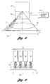
- Figure 3 depicts a cross-sectional, schematic view of a stack of APAP devices according to one embodiment of the present invention;
- Figures 4a and 4b depict fragmented, cross-sectional, schematic views of a windshield pre-treatment step and windshield bonding step according to one embodiment of the present invention;
- Figures 5a, 5b and 5c depict the results of a lap shear failure tests on bonded coupons prepared using one or more embodiments of the present invention;
- Figures 6 and 7 depict the results of a lap shear failure tests on bonded coupons prepared using one or more embodiments of the present invention;
- Figure 8 shows a perspective view of a portion of a relatively dirty windshield according to one embodiment of the present invention;
- Figure 9 shows the results of quick knife adhesion (QKA) tests on a dirty glass sample according to one embodiment of the present invention;
- Figure 10 shows the results of tests on an air plasma pre-treated glass according to one embodiment of the present invention; and
- Figures 11a and 11b show the results of quick knife adhesion (QKA) tests performed on a treated and untreated glass according to one embodiment of the present invention.
- Except where expressly indicated, all numerical quantities in this description indicating amounts of material or conditions of reaction and/or use are to be understood as modified by the word "about" in describing the broadest scope of the present invention. Practice within the numerical limits stated is generally preferred.
- The description of a single material, compound or constituent or a group or class of materials, compounds or constituents as suitable for a given purpose in connection with the present invention implies that mixtures of any two or more single materials, compounds or constituents and/or groups or classes of materials, compounds or constituents are also suitable. Also, unless expressly stated to the contrary, percent, "parts of," and ratio values are by weight. Description of constituents in chemical terms refers to the constituents at the time of addition to any combination specified in the description, and does not necessarily preclude chemical interactions among constituents of the mixture once mixed. The first definition of an acronym or other abbreviation applies to all subsequent uses herein of the same abbreviation and applies mutatis mutandis to normal grammatical variations of the initially defined abbreviation. Unless expressly stated to the contrary, measurement of a property is determined by the same technique as previously or later referenced for the same property.
- Referring now to Figure 1 there is shown a cross-sectional view of an atmospheric pressure air plasma (APAP)
device 10 suitable for applying anair plasma stream 12 to abonding surface 14 of asubstrate 16. Non-limiting examples ofsubstrate 16 include glass and fritted glass. Other examples include, but are not limited to, polycarbonate glazing or other polymeric glazing, chemical vapour deposited metal oxide coatings on polycarbonate or other polymeric glazing, polymeric trim moulding such as reaction injection moulding (RIM) that may serve as an interface between side glass and a vehicle bonding flange. - The
APAP device 10 includes avoltage supply 18 for supplying voltage toelectrode 20 andground 22 for grounding theAPAP device 10. Ionizing gas, e.g. air, is fed into afirst chamber 24 throughinlet 26. Other ionizing gases can be used to generate plasma streams. Non-limiting examples of ionizing gases for the plasma stream include oxygen and oxygen diluted in an inert gas, e.g. nitrogen, argon or helium. The ionizing gas exits thefirst chamber 24 intoelectrode 20, which is situated withindischarge area 28. -
Electrode 20 generates aplasma beam 30 that is projected downward throughplasma nozzle 32 and exits throughoutlet 34. Theplasma beam 30contacts bonding surface 14, and in so doing, cleans thebonding surface 14 and activates it for bonding. - The
plasma beam 30 can travel along the bonding surface at a velocity in the range of 16 to 840 mm/s according to certain embodiments of the present invention. In other embodiments, the velocity can be in the range of 150 to 450 mm/s. It should be appreciated that the delivery of theplasma beam 30 to thebonding surface 14 can be discontinued and/or continued several times during application. For example, raster patterns with spacings can be used as an application strategy, wherein thebeam 30 is discontinued and continued to achieve the desired pattern. - In another embodiment, as depicted schematically in cross-section in Figure 2, an off-
axis plasma nozzle 36 havingspray angle 37 is attached toAPAP device 10. Thenozzle 36 is rotated by anelectronic motor 38 to produce a substantialcylindrical spray pattern 40. In at least one embodiment, thedevice 10 andnozzle 36 combination linearly moves above thesubstrate surface 14 to impart an air plasma treatment ofnominal width 42. - In certain embodiments, the spray angle is in the range of 0 to 30 degrees and the rotation speed in the range of 2000 to 3000 revolutions per minute. The linear movement velocity can be in the range of 16 to 300 mm/s. According to this embodiment, the
plasma 12 can be applied to thesubstrate surface 14 in widths of 6 to 57 mm (0.25 to 2.25 inches) per treatment pass and in certain embodiments, 50mm (2 inches) per treatment pass. It should be appreciated that the treatment width is a function of nozzle spray angle and the height offset between thesubstrate surface 14 andlower end 44 ofAPAP device 10. - In another embodiment, as depicted schematically in cross section in Figure 3, a number of
APAP devices 10 are linearly configured to provide a treatment pass ofwidth 46 while travelling in a direction transverse to the linear direction of the configuredAPAP devices 10. The number of APAP devices can be in the range of two to eight. In Figure 3 a fourAPAP device configuration 48 is depicted. In at least one embodiment, each APAP device generates a stream having a 6 mm width, thereby generating a 24 mm treatment width. - According to at least one embodiment, the APAP device can be a device manufactured by PlasmaTreat of PlasmaTreat North America, Inc. of Mississauga, Ontario. According to other embodiments, an APAP device disclosed in
U.S. Pat. App. No. 11/162,741, filed September 21, 2005 - According to at least one embodiment, the present invention includes applying an air plasma to the substrate surface for cleaning and activating the surface prior to bonding. This step can be utilized to pre-treat windshield glass prior to bonding. In certain embodiments, the windshield can be at least partially coated with a ceramic frit material. The air plasma pre-treatment is especially useful for activating the fritted surface. While not wanting to be bound to any particular theory, the air plasma pre-treatment activates the fritted surface by adding hydroxyl groups that can form relative strong covalent bonds with the adhesive.
- Figure 4a depicts a fragmented, cross-sectional view of a
windshield 50 receiving anair plasma pre-treatment 51.Windshield 50 includes a frittedportion 53, which may be covered with contaminants resulting from exposure to a manufacturing environment and/or a slip coat that is typically applied to the edge of the windshield adjacent to the fritted portion to facilitate attachment of a protective moulding. The slip coat is typically a silicone based material.APAP device 10 applies an air plasma to clean and activate thebonding surface 54 ofwindshield 50 prior to bonding. After this step, an adhesive 56, in certain embodiments, a moisture-cured urethane adhesive, is applied to at least a portion of the pre-treated area. Other non-limiting examples of adhesives include moisture-cured silicone adhesives, 1-part and 2-part urethane, silicone and epoxy adhesives, butyls, acrylics and cyanic-acrylics, and hot-melt thermoplastic adhesives. Then, thewindshield 50 is bonded to frame 52 throughadhesive 56, as depicted in Figure 4b. In certain embodiments, the air plasma cleaning and activation step replaces the one or more solvent cleaning steps used in conventional pre-treatment processes. - The air plasma cleaning and activating step can be accomplished manually or robotically with the air plasma treatment being performed just prior to dispensing a urethane windshield adhesive in a sequential one pass treatment and application. Alternatively, a double pass can be utilized where the first pass is the air plasma treatment and activation step and the second pass is the application of an adhesive under a similar robot or manual path.
- It should be appreciated that glass substrates can be fritted with a ceramic frit compound. According to one embodiment, the adhesive can be selected based on the ceramic frit compound. The following non-limiting parameters that can be considered in selecting the adhesive and glass substrate pair: (1) ceramic frit chemistry; (2) chemistry of the adjoining substrate and/or (3) processing adhesives dictated by the manufacturing plant conditions and production cycle times.
- According to one embodiment, Dow 15626 urethane adhesive is selected for a Ferro 24-8708 Bi-based fritted glass.
- The following non-limiting examples demonstrate the use of the air plasma cleaning and activation process according to certain embodiments of the present invention.
- Durability tests were conducted on bonded substrates prepared according to one embodiment of the present invention. The preparation of the bonded substrates was conducted under laboratory conditions. A Ferro 24-8708 bismuth-based enamel coated glass tab, available from Ferro Corp. of Washington, Pennsylvania was used as a first substrate. The dimensions of the glass tab were 25 x 100 mm (1x4 inch) by 5.6 mm thickness. A 25 x 100 mm (1x4 inch) DuPont Cormax 6 electro-plate immersion de-ionized water coated unpolished cold-rolled steel panel (CRS), available from ACT Laboratories, Inc., was used as a second substrate.
- The bonding surface of the first substrate was cleaned and activated by the application of an air plasma via the
APAP device 10 as shown in Figure 1. After the air plasma application, the first substrate was joined to the second substrate using the Dow 15626 urethane adhesive, available from Dow Chemical of Midland, Michigan. - Three bonded
samples substrates sample glass tab 66 coated with anenamel 68 and ametal coupon 70, which are joined by an adhesive 72. - Each of the samples was exposed for 2 weeks of 95% relative humidity (R.H.) at 38°C. After the exposure period, each
sample samples - In each test, the bond between the adhesive 72 and the enamel-coated
glass substrate 68, did not fail. Instead, failure occurred cohesively, either within the adhesive 72 or the enamel-coatedglass substrate 68. While not wanting to be bound to any particular theory or principle, the results of this test reveal that, under laboratory conditions, good adhesive-to-glass bonding can be achieved directly. - Turning to Figure 6, a durability test was conducted on a bonded
substrate sample 74 prepared by bonding an enamel-coatedglass substrate 76 andmetal coupon 78 with an adhesive 80. The same materials and bonding process of Example 1 were used in Example 2. In contrast to the exposure conditions of Example 1, thesample 74 of Example 2 was exposed to 5 weeks of 95% R.H. at 38°C. After the exposure period,sample 74 was subjected to a lapshear pull to failure test. - Figure 6 shows the result of this test. The bond between the adhesive 80 and the enamel-coated
glass substrate 76 did not fail. Instead, failure occurred cohesively, either within the adhesive 80 or enamel-coatedglass substrate 76. While not wanting to be bound to any particular theory or principles, the results of this test reveal that, under laboratory conditions, good adhesive-to-glass bonding can be achieved directly. - Turning to Figure 7, a durability test was conducted on a bonded
substrate sample 82 by bonding an enamel-coatedglass substrate 84 andmetal coupon 86 with an adhesive 88. The same materials and bonding process of Example 1 were used in this example. In contrast to the exposure conditions of Example 1, the sample of Example 3 was exposed to 2 weeks of 95% R.H. at 38°C, followed immediately by immersion in water at 69°C for 2 weeks. After the exposure period, thesample 82 was subjected to a lapshear pull to failure test. - Figure 7 shows the result of this test. The bond between the adhesive 88 and the enamel-coated
glass substrate 84 did not fail. Instead, failure occurred cohesively, either within the adhesive 88 or enamel-coatedglass substrate 84. While not wanting to be bound to any particular theory, the results of this test reveal that, under laboratory conditions, good adhesive-to-glass bonding can be achieved directly. - Turning to Figure 8, a fragmented perspective view of a
windshield 100 is depicted. Thewindshield 100 includes a frittedportion 102 and anon-fritted portion 104.Windshield 100 is glass material treated with a Zn-based ceramic frit to obtain a frittedportion 102. In certain applications, bonding occurs in at least a portion of the frittedportion 102 during assembly of the windshield to the vehicle frame. - Figure 9 shows a
glass substrate 150 used as a windshield sample for purposes of this example. Theglass substrate 150 was partially coated with a Zn-based ceramic frit to obtain frittedportion 152. Theglass substrate 150 also includesnon-fritted portion 154. Theglass 150 was exposed to air for a one year period to simulate the conditions in a manufacturing environment. During this time period, contaminants, e.g. dust and dirt, collected on the surface ofglass 150. - The dirty surface was assessed for adhesion enhancement by applying
adhesive beads - Figure 9 shows the QKA test results for
dirty glass 150 for theadhesive bead 156 applied to the frittedportion 152 and theadhesive beads non-fritted portion 154. The QKA test shows adhesive failure between theadhesive bead 156 andnon-fritted portion 152 and theadhesive bead 158 andnon-fritted portion 154. While not wanting to be bound to any particular theory, these results suggest that the dirt remaining on the glass after one (1) year of laboratory exposure was sufficient to disrupt the formation of bond linkages that, under clean conditions, can be achieved directly. - According to conventional adhesive-to-glass bonding methods, the fritted glass is typically treated with one or more primers to clean the contaminants and activate the fritted glass for the adhesive bonding step.
- According to Example 5, a primerless pre-treatment process was employed. The surface of the
glass 200 of Figure 10 was cleaned and activated via application of an air plasma from an APAP device, utilizing a raster pattern with 2 mm spacing between passes at a velocity of 25 mm/s and a distance of 8 mm. TheAPAP device 10 depicted in Figure 1 can be used for this application. -
Glass sample 200 was cleaned and activated using air plasma, and then tested for adhesion. The results of this test are depicted in Figure 10.Adhesive bead 206 was applied to frittedarea 202 and adhesive bead 208 was applied tonon-fritted area 204. In this example,adhesive beads 206 and 208 can be removed, with force, only partially from the frittedarea 202, and cannot be removed from the adjacentnon-fritted area 204. While not wanting to be bound by any theory or principle, this result demonstrates that the glass surface was cleaned from dirt and activated chemically for adhesive bonding through treatment by APAP. - A measure of the cleaning ability of the air plasma pre-treatment can be demonstrated through surface chemical analysis using X-ray photoelectron spectroscopy (XPS). In this example, a fritted glass with a Zn-based ceramic frit was tested. An air plasma stream rotating at 2000 rpm was passed twice over the fritted glass and adjacent glass surface at a speed of 33 mm/s and distance of 8 mm. The differences in surface chemistry of zinc-based ceramic fritted glass before and after treatment with atmospheric pressure air plasma are shown in Table 1.
Table 1 Sample Atomic Concentration % % Reduction in Carbon C O Si Others Dirty frit 52.0 36.9 2.0 9.0 32.5 Plasma cleaned frit 35.1 48.5 2.6 13.8 Dirty Glass 32.3 46.1 11.7 9.8 57.3 Plasma cleaned glass 13.8 58.7 16.6 11.0 - For these treatments, XPS surface analysis revealed that 32.5% of the contaminant carbon layer was removed from the fritted surface, and 57.3% of the carbon layer was removed from the glass surface.
- Another example of an air plasma cleaning and activation process was demonstrated on a slip coat film contaminated windshield. A slip coat can refer to a silicone-based rubbery material that is used to improve sealing and reduce noise, vibration and harshness (NVH) of a thermoplastic elastomer (TPE) windshield moulding.
- For this experiment and according to Figures 11a and 11b, two 25 x 100mm (1x4 inch) Ferro 24-8708 Bi-based fritted
glass coupons coupon 258 was treated with an air plasma stream rotating at 2000 rpm at a distance of 8 mm and a speed of 50 mm/s. After the treatment, the slip coat film was no longer visible on the frit surface. EFTEC EF7010 urethane adhesive was then applied to bothcoupons adhesive beads - The QKA test was performed on the
adhesive beads Coupon 250, which was not treated with air plasma, exhibited facile delamination of the adhesive bead from the fritted glass coupon. The QKA test did not remove theadhesive bead 256 from thecoupon 258, which was treated with air plasma. Instead, the adhesive bead tenaciously adhered tocoupon 258. Inregion 260, some cohesive failure occurred, but no delamination. - A measure of the cleaning ability of the air plasma pre-treatment when a slip coat contaminant is present can be demonstrated through surface chemical analysis using X-ray photoelectron spectroscopy (XPS). In this example, a fritted glass with a Bi-based ceramic frit was tested. An air plasma stream was applied in a raster pattern over the fritted glass and adjacent glass surface at a spacing of 3 mm at a speed of 300 mm/s and distance of 6 mm. The differences in surface chemistry of bismuth-based ceramic fritted glass before and after treatment with atmospheric pressure air plasma are shown in Table 2.
Table 2 Sample Atomic Concentration % % Reduction in Silicone C O Si as Silicone Others Slip coat contaminated frit 49.7 34.4 11.6 4.4 57.8 Plasma cleaned frit 10.8 63.6 4.9 20.7 Slip coat contaminated glass 55.8 27.4 15.0 1.8 72.0 Plasma cleaned glass 15.4 59.1 4.2 21.3 - For these treatments, XPS surface analysis revealed that 57.8% of the contaminant silicone layer was removed from the fritted surface, and 72.0% of the silicone layer was removed from the glass surface.
- The XPS surface analysis also revealed that the hydroxyl content of the bismuth-based ceramic fritted glass increases from 8.9 weight percent before air plasma treatment to 15.0 weight percent after air plasma treatment.
- While not wanting to be bound by any theory or principle, these results demonstrate that the fritted-glass surface was effectively cleaned from the contaminant layer and activated chemically for adhesive bonding.
- Therefore in summary, one aspect of the present invention relates to a method and system of treating substrates for bonding that increases the reliability of the resulting substrate bond. Examples of suitable substrates include, without limitation, glass and coated glass. One example of a coating is a ceramic frit. Another aspect of the present invention is a method and system that simplifies and/or automates a glass bonding process. Advantageously, the present invention treats substrates for bonding without the use of solvent-based primers.
- A method of bonding a windscreen to a frame of a motor vehicle in accordance with the invention comprises pretreating a bondable portion of the windscreen glass by applying an air plasma thereto, applying an adhesive to the bondable portion of the windscreen and adhesively bonding the windscreen to the frame by bring the adhesive coated portion of the windscreen into contact with the frame.
- It will be appreciated by those skilled in the art that although the invention has been described by way of example with reference to one or more embodiments it is not limited to the disclosed embodiments and that one or more modifications to the disclosed embodiments or alternative embodiments could be constructed without departing from the scope of the invention as set forth in the appended claims.
Claims (10)
- A method of treating a glass substrate for bonding characterised in that the method comprises providing a glass substrate (50) having a fritted portion (53) of a ceramic frit material at least a portion of which forms a bondable surface (54) and a non-fritted portion and applying an air plasma (51) to the bondable surface (54) so as to pre-treat it for subsequent bonding.
- A method of treating a glass substrate for bonding as claimed in claim 1 wherein applying an air plasma to the bondable surface (54) comprises cleaning and activating the bondable surface (54) for subsequent bonding by directing the air plasma (51) onto the bondable surface (54).
- A method of treating a glass substrate for bonding as claimed in claim 2 wherein the bondable surface (54) includes a contaminant layer and the cleaning step at least partially removes the contaminant layer.
- A method of treating a glass substrate for bonding as claimed in wherein the contaminant layer comprises a slip coat composition.
- A method of providing a glass substrate for bonding characterised in that the method comprises using a method of treating a glass substrate for bonding as claimed in any of claims 1 to 4 and applying an adhesive (56) to the fritted portion (53) for subsequent bonding.
- A method of providing a glass substrate for bonding as claimed in claim 5 wherein the method further comprises selecting an adhesive composition based on the ceramic frit material and bonding the adhesive (56) to the bondable surface (54) of the glass substrate (50).
- A method of providing a glass substrate for bonding as claimed in claim 5 or in claim 6 wherein the method further comprises providing a second substrate (52) and bonding the first substrate (50) to the second substrate (52) using the adhesive (56).
- A method of providing a glass substrate for bonding as claimed in claim 7 wherein the glass substrate is a windshield (50) for a motor vehicle and the second substrate is a frame (52) of the motor vehicle.
- A fritted glass substrate for use in subsequent bonding that has been pre-treated using a method of treating a glass substrate for bonding as claimed in any of claims 1 to 4 characterised in that the substrate has a fritted portion including a bondable surface portion and a contaminant layer at least partially contacting the bondable surface portion of the substrate, the contaminant layer having an atomic concentration percentage of Si as silicone of less than 5.0 percent.
- A pre-treated fritted glass substrate as claimed in claim 9 wherein the bondable surface portion comprises a bismuth-based ceramic material having a hydroxyl content of greater than 15.0 percent by weight.
Applications Claiming Priority (1)
| Application Number | Priority Date | Filing Date | Title |
|---|---|---|---|
| US11/427,023 US7744984B2 (en) | 2006-06-28 | 2006-06-28 | Method of treating substrates for bonding |
Publications (1)
| Publication Number | Publication Date |
|---|---|
| EP1873127A1 true EP1873127A1 (en) | 2008-01-02 |
Family
ID=38524768
Family Applications (1)
| Application Number | Title | Priority Date | Filing Date |
|---|---|---|---|
| EP07109042A Withdrawn EP1873127A1 (en) | 2006-06-28 | 2007-05-28 | A method of treating substrates for bonding |
Country Status (3)
| Country | Link |
|---|---|
| US (1) | US7744984B2 (en) |
| EP (1) | EP1873127A1 (en) |
| CN (1) | CN101096293B (en) |
Families Citing this family (15)
| Publication number | Priority date | Publication date | Assignee | Title |
|---|---|---|---|---|
| US8029870B2 (en) * | 2008-03-24 | 2011-10-04 | GM Global Technology Operations LLC | Method of coating fuel cell components for water removal |
| US9217066B2 (en) * | 2008-03-31 | 2015-12-22 | Ford Global Technologies, Llc | Structural polymer insert and method of making the same |
| US8058144B2 (en) * | 2008-05-30 | 2011-11-15 | Analog Devices, Inc. | Method for capping a MEMS wafer |
| US8197909B2 (en) | 2008-08-26 | 2012-06-12 | Ford Global Technologies, Llc | Plasma coatings and method of making the same |
| WO2012015936A1 (en) | 2010-07-27 | 2012-02-02 | Agc Automative Americas R&D Inc. | Window assembly having a primer |
| EP2702840A1 (en) * | 2011-04-27 | 2014-03-05 | Dow Corning France | Plasma treatment of substrates |
| JP2015528859A (en) | 2012-06-24 | 2015-10-01 | ゲイツ コーポレイション | Carbon cord for reinforced rubber products and its products |
| CN103639157B (en) * | 2013-11-15 | 2016-06-08 | 广州福耀玻璃有限公司 | The surface treatment method of glass adnexa |
| US20150318527A1 (en) * | 2014-05-05 | 2015-11-05 | Ford Global Technologies, Llc | Plasma treatment of an electrochemical membrane |
| CN106286516A (en) * | 2016-08-31 | 2017-01-04 | 广东紫丁香实业股份有限公司 | A way to connect the handle |
| US10101149B1 (en) | 2017-04-12 | 2018-10-16 | Ford Global Technologies, Llc | Methods to control adhesiveness using topography |
| US20190322016A1 (en) | 2018-04-23 | 2019-10-24 | Ford Global Technologies, Llc | Method for bonding injection molded plastics |
| CN108499985B (en) * | 2018-05-02 | 2024-03-29 | 信义汽车玻璃(深圳)有限公司 | Glass surface cleaning equipment |
| CN110205040A (en) * | 2019-06-28 | 2019-09-06 | 江苏铁锚玻璃股份有限公司 | Glass, the adhesive method of metal and film, aircraft glass and preparation method thereof |
| CN118270992A (en) * | 2024-03-12 | 2024-07-02 | 东南大学 | A process to improve the adhesion between glass and polymer |
Citations (5)
| Publication number | Priority date | Publication date | Assignee | Title |
|---|---|---|---|---|
| WO2003000612A1 (en) * | 2001-06-20 | 2003-01-03 | Henkel Teroson Gmbh | Method for gluing a pane |
| US20030098114A1 (en) * | 2001-11-29 | 2003-05-29 | Andon Samurkas | Method of bonding a window to a substrate without a primer |
| US20030138573A1 (en) * | 2002-01-23 | 2003-07-24 | Glasshield Patent Holding Company, Ltd. | Method and Apparatus for Applying Material to Glass |
| EP1524248A1 (en) * | 2003-10-17 | 2005-04-20 | Corning Incorporated | A method for bonding glass or metal fluoride optical materials to metal |
| WO2006083758A1 (en) * | 2005-02-02 | 2006-08-10 | Nordson Corporation | Apparatus and method for plasma treating and dispensing an adhesive/sealant onto a part |
Family Cites Families (48)
| Publication number | Priority date | Publication date | Assignee | Title |
|---|---|---|---|---|
| US3811925A (en) * | 1971-10-28 | 1974-05-21 | Engelhard Ind | Method of applying a hot luster coating to glass by electrostatic means |
| JPS58167602A (en) | 1982-03-29 | 1983-10-03 | Futaba Corp | Formation of thin film of organic substance |
| US4682711A (en) | 1985-04-08 | 1987-07-28 | Nordson Corporation | Method and apparatus for sealing welded seams of automobiles |
| US5169675A (en) | 1987-07-02 | 1992-12-08 | The Standard Oil Company | Bonding of high nitrile resins onto surface plasma treated plastics |
| JPH01305843A (en) * | 1988-06-01 | 1989-12-11 | Agency Of Ind Science & Technol | Production of high strength clay compound ceramics |
| NZ227050A (en) | 1988-11-22 | 1992-04-28 | Contra Shear Holdings | Pressure separation apparatus; rotating drum screen with tangential ejection nozzles |
| IT1228120B (en) | 1988-12-23 | 1991-05-28 | Eniricerche Spa | PROCEDURE FOR OBTAINING A MULTI-FUNCTIONAL IONOSELECTIVE MEMBRANE SENSOR |
| AU8331791A (en) | 1990-08-22 | 1992-03-17 | Sommer S.A. | Textile fiber treatment, devices therefore as well as products obtained with the process |
| US5185182A (en) | 1990-12-10 | 1993-02-09 | Ford Motor Company | Method for inhibiting significant oxidation of a film on a substance during heating |
| US5730922A (en) | 1990-12-10 | 1998-03-24 | The Dow Chemical Company | Resin transfer molding process for composites |
| DE69218811T2 (en) | 1991-01-23 | 1997-07-17 | Matsushita Electric Industrial Co., Ltd., Kadoma, Osaka | Water and oil repellent adsorbed film and process for its manufacture |
| JPH075773B2 (en) | 1992-12-22 | 1995-01-25 | 工業技術院長 | Surface modification method of fluoropolymer moldings using ultraviolet laser |
| US5585187A (en) | 1994-05-23 | 1996-12-17 | Sumitomo Chemical Company, Limited | Methods for surface treating and paint-coating resin composition molded articles and paint-coated article obtained by said method for paint-coating |
| US6218004B1 (en) | 1995-04-06 | 2001-04-17 | David G. Shaw | Acrylate polymer coated sheet materials and method of production thereof |
| US5829804A (en) | 1995-06-27 | 1998-11-03 | Mitsui Chemicals, Inc. | Resin composition for use in the making of automobile bumpers and automobile bumpers made thereof |
| DE19532412C2 (en) | 1995-09-01 | 1999-09-30 | Agrodyn Hochspannungstechnik G | Device for surface pretreatment of workpieces |
| EP0769331A1 (en) | 1995-10-06 | 1997-04-23 | Ford Motor Company | Method for identifying and protecting an activated plastic surface |
| CN2255914Y (en) * | 1995-10-30 | 1997-06-11 | 张毓麟 | Electrostatic absorbing device for artificial surface paneling apparatus |
| US6306514B1 (en) * | 1996-12-31 | 2001-10-23 | Ansell Healthcare Products Inc. | Slip-coated elastomeric flexible articles and their method of manufacture |
| US5820808A (en) | 1997-01-16 | 1998-10-13 | Ford Global Technologies, Inc. | Additive and method for in situ surface modification of injection molded polymers |
| US5916674A (en) | 1997-02-05 | 1999-06-29 | Ford Motor Company | Article having a removable protective film |
| US5820991A (en) * | 1997-02-24 | 1998-10-13 | Cabo; Ana M. | Fused glass sheets having ceramic paint and metal foil and method of making same |
| US5885716A (en) * | 1997-08-14 | 1999-03-23 | Osaka Municipal Government | Material and process for forming composite film |
| CN100349994C (en) | 1998-04-15 | 2007-11-21 | Basf涂料日本株式会社 | Coating film forming method and coating composition |
| US6503564B1 (en) | 1999-02-26 | 2003-01-07 | 3M Innovative Properties Company | Method of coating microstructured substrates with polymeric layer(s), allowing preservation of surface feature profile |
| US6316099B1 (en) * | 1999-03-31 | 2001-11-13 | 3M Innovative Properties Company | Multi-layered sealant |
| US6649225B2 (en) | 1999-04-07 | 2003-11-18 | Board Of Trustees Of Michigan State University | Process for the treatment of a fiber |
| US6565927B1 (en) | 1999-04-07 | 2003-05-20 | Board Of Trustees Of Michigan State University | Method for treatment of surfaces with ultraviolet light |
| WO2000071340A1 (en) | 1999-05-20 | 2000-11-30 | Sport Court, Inc. | Method and apparatus for coating a floor tile |
| DE29919142U1 (en) | 1999-10-30 | 2001-03-08 | Agrodyn Hochspannungstechnik GmbH, 33803 Steinhagen | Plasma nozzle |
| ES2220711T3 (en) | 2000-02-11 | 2004-12-16 | Dow Corning Ireland Limited | ATMOSPHERIC PRESSURE PLASMA SYSTEM. |
| US6676762B2 (en) | 2001-01-15 | 2004-01-13 | Board Of Trustees Of Michigan State University | Method for cleaning a finished and polished surface of a metal automotive wheel |
| US20060118242A1 (en) | 2001-02-12 | 2006-06-08 | Anthony Herbert | Atmospheric pressure plasma system |
| US6793759B2 (en) | 2001-10-09 | 2004-09-21 | Dow Corning Corporation | Method for creating adhesion during fabrication of electronic devices |
| JP2003147325A (en) | 2001-11-14 | 2003-05-21 | Nitto Denko Corp | Surface-modified pressure-sensitive adhesive, method for surface-modifying pressure-sensitive adhesive, and pressure-sensitive adhesive tape or sheet |
| US6821379B2 (en) | 2001-12-21 | 2004-11-23 | The Procter & Gamble Company | Portable apparatus and method for treating a workpiece |
| CA2477285C (en) | 2002-03-02 | 2011-05-03 | Polymeric Converting Llc | Removable labels, coupons and the like |
| US20030207099A1 (en) | 2002-05-01 | 2003-11-06 | Gillmor Susan D. | Low-contact-angle polymer membranes and method for fabricating micro-bioarrays |
| US6841263B2 (en) | 2002-05-03 | 2005-01-11 | The John Hopkins University | Method of adhering a solid polymer to a substrate and resulting article |
| DE10250281A1 (en) | 2002-10-28 | 2004-05-13 | Nanogate Technologies Gmbh | Coating processes and coating agents |
| US20060162740A1 (en) | 2005-01-21 | 2006-07-27 | Cerionx, Inc. | Method and apparatus for cleaning and surface conditioning objects using non-equilibrium atmospheric pressure plasma |
| EP1524548A1 (en) | 2003-10-14 | 2005-04-20 | Alcatel | Stabilization of modulators for rz-modulation formats |
| US7176268B2 (en) | 2003-12-05 | 2007-02-13 | Bausch & Lomb Incorporated | Prepolymers for improved surface modification of contact lenses |
| JP4991310B2 (en) | 2003-12-16 | 2012-08-01 | サン・ケミカル・コーポレーション | Radiation curable coating manufacturing method and coated article |
| WO2005089957A1 (en) | 2004-03-15 | 2005-09-29 | Ciba Specialty Chemicals Holding Inc. | Process for the production of strongly adherent coatings |
| ES2328611T3 (en) * | 2004-12-17 | 2009-11-16 | Exxonmobil Chemical Patents Inc. | FILMS OF POLYMER BLENDS. |
| US20060237030A1 (en) | 2005-04-22 | 2006-10-26 | Cerionx, Inc. | Method and apparatus for cleaning and surface conditioning objects with plasma |
| WO2006125038A1 (en) | 2005-05-17 | 2006-11-23 | Exxnonmobil Research And Engineering Company | Paint system and method of painting fiber reinforced polypropylene composite components |
-
2006
- 2006-06-28 US US11/427,023 patent/US7744984B2/en not_active Expired - Fee Related
-
2007
- 2007-05-28 EP EP07109042A patent/EP1873127A1/en not_active Withdrawn
- 2007-06-26 CN CN2007101094716A patent/CN101096293B/en not_active Expired - Fee Related
Patent Citations (5)
| Publication number | Priority date | Publication date | Assignee | Title |
|---|---|---|---|---|
| WO2003000612A1 (en) * | 2001-06-20 | 2003-01-03 | Henkel Teroson Gmbh | Method for gluing a pane |
| US20030098114A1 (en) * | 2001-11-29 | 2003-05-29 | Andon Samurkas | Method of bonding a window to a substrate without a primer |
| US20030138573A1 (en) * | 2002-01-23 | 2003-07-24 | Glasshield Patent Holding Company, Ltd. | Method and Apparatus for Applying Material to Glass |
| EP1524248A1 (en) * | 2003-10-17 | 2005-04-20 | Corning Incorporated | A method for bonding glass or metal fluoride optical materials to metal |
| WO2006083758A1 (en) * | 2005-02-02 | 2006-08-10 | Nordson Corporation | Apparatus and method for plasma treating and dispensing an adhesive/sealant onto a part |
Also Published As
| Publication number | Publication date |
|---|---|
| CN101096293B (en) | 2012-07-18 |
| US20080003436A1 (en) | 2008-01-03 |
| CN101096293A (en) | 2008-01-02 |
| US7744984B2 (en) | 2010-06-29 |
Similar Documents
| Publication | Publication Date | Title |
|---|---|---|
| US7744984B2 (en) | Method of treating substrates for bonding | |
| US8048530B2 (en) | Method of coating a substrate for adhesive bonding | |
| EP1451123B1 (en) | Method of bonding a window to a substrate without a primer | |
| US20100151236A1 (en) | Surface treatment for polymeric part adhesion | |
| US20100209618A1 (en) | Method for plasma treatment and painting of a surface | |
| JP2005511463A5 (en) | ||
| US20040258850A1 (en) | Environmentally friendly reactive fixture to allow localized surface engineering for improved adhesion to coated and non-coated substrates | |
| EP0332344B1 (en) | A method for obtaining adhesion of urethane sealant to a painted or glass surface | |
| CN101321614B (en) | Method for surface treatment of composite material structure by using atmospheric plasma beam | |
| RU2401200C2 (en) | Metal element with fixation-prone coat | |
| Hong et al. | The modification of epoxy/metal interphases by adsorbed contaminants | |
| Ghanem et al. | Introduction to polymer adhesion | |
| CA2339815C (en) | Environmental wipe solvent compositions and processes | |
| US8586149B2 (en) | Environmentally friendly reactive fixture to allow localized surface engineering for improved adhesion to coated and non-coated substrates | |
| US20190322016A1 (en) | Method for bonding injection molded plastics | |
| US6872269B2 (en) | Process for bonding contaminated substrates | |
| EP1522574B1 (en) | Environmental wipe solvent compositions and processes | |
| CN119789944A (en) | Method of bonding a layer of elastomeric material to an aluminum substrate | |
| Gutowski et al. | The mechanism of adhesion improvement of elastomeric silicone sealants to difficult-to-bond polymeric substrates through reactive or interpenetrating molecular brushes | |
| RU2378117C1 (en) | Method of surface processing of composite material structures by plasma beams at atmospheric pressure | |
| Lommatzsch | 100 percent increase in ageing resistance: Plasma coating at atmospheric pressure | |
| Glogauer | Plasma treatment: Reduction of VOC emissions and improvement of environmentally sensitive processes with plasma surface treatment prior to bonding, coating and printing applications | |
| Rhodes Sr | SILICONE ADHESIVES AND PRIMERS ON LOW SURFACE ENERGY PLASTICS AND HIGH STRENGTH METALS | |
| Sukumar | Water Based Silane Coupling Agents for Bonding Polyacrylate Rubber to Aluminum | |
| Hockridge et al. | Adhesive bonding and the use of corrosion resistant primers |
Legal Events
| Date | Code | Title | Description |
|---|---|---|---|
| PUAI | Public reference made under article 153(3) epc to a published international application that has entered the european phase |
Free format text: ORIGINAL CODE: 0009012 |
|
| AK | Designated contracting states |
Kind code of ref document: A1 Designated state(s): AT BE BG CH CY CZ DE DK EE ES FI FR GB GR HU IE IS IT LI LT LU LV MC MT NL PL PT RO SE SI SK TR |
|
| AX | Request for extension of the european patent |
Extension state: AL BA HR MK YU |
|
| 17P | Request for examination filed |
Effective date: 20080626 |
|
| AKX | Designation fees paid |
Designated state(s): DE ES FR GB IT |
|
| 17Q | First examination report despatched |
Effective date: 20090127 |
|
| STAA | Information on the status of an ep patent application or granted ep patent |
Free format text: STATUS: EXAMINATION IS IN PROGRESS |
|
| STAA | Information on the status of an ep patent application or granted ep patent |
Free format text: STATUS: THE APPLICATION IS DEEMED TO BE WITHDRAWN |
|
| 18D | Application deemed to be withdrawn |
Effective date: 20191203 |