EP1873022B1 - Occupant protection apparatus and method - Google Patents
Occupant protection apparatus and method Download PDFInfo
- Publication number
- EP1873022B1 EP1873022B1 EP07111173A EP07111173A EP1873022B1 EP 1873022 B1 EP1873022 B1 EP 1873022B1 EP 07111173 A EP07111173 A EP 07111173A EP 07111173 A EP07111173 A EP 07111173A EP 1873022 B1 EP1873022 B1 EP 1873022B1
- Authority
- EP
- European Patent Office
- Prior art keywords
- seat
- occupant
- airbag
- seated
- ecu
- Prior art date
- Legal status (The legal status is an assumption and is not a legal conclusion. Google has not performed a legal analysis and makes no representation as to the accuracy of the status listed.)
- Not-in-force
Links
- 238000000034 method Methods 0.000 title claims description 10
- 230000000452 restraining effect Effects 0.000 claims description 12
- 230000002401 inhibitory effect Effects 0.000 claims description 5
- 238000001514 detection method Methods 0.000 description 14
- 230000000052 comparative effect Effects 0.000 description 13
- 230000002159 abnormal effect Effects 0.000 description 4
- 230000001133 acceleration Effects 0.000 description 4
- 210000004705 lumbosacral region Anatomy 0.000 description 4
- 210000000689 upper leg Anatomy 0.000 description 4
- 230000004308 accommodation Effects 0.000 description 3
- 210000001217 buttock Anatomy 0.000 description 3
- 238000010586 diagram Methods 0.000 description 3
- 238000003780 insertion Methods 0.000 description 3
- 230000037431 insertion Effects 0.000 description 3
- 239000004744 fabric Substances 0.000 description 2
- 230000008878 coupling Effects 0.000 description 1
- 238000010168 coupling process Methods 0.000 description 1
- 238000005859 coupling reaction Methods 0.000 description 1
- 239000010985 leather Substances 0.000 description 1
- 239000000837 restrainer Substances 0.000 description 1
Images

Classifications
-
- B—PERFORMING OPERATIONS; TRANSPORTING
- B60—VEHICLES IN GENERAL
- B60R—VEHICLES, VEHICLE FITTINGS, OR VEHICLE PARTS, NOT OTHERWISE PROVIDED FOR
- B60R21/00—Arrangements or fittings on vehicles for protecting or preventing injuries to occupants or pedestrians in case of accidents or other traffic risks
- B60R21/02—Occupant safety arrangements or fittings, e.g. crash pads
- B60R21/16—Inflatable occupant restraints or confinements designed to inflate upon impact or impending impact, e.g. air bags
- B60R21/20—Arrangements for storing inflatable members in their non-use or deflated condition; Arrangement or mounting of air bag modules or components
- B60R21/207—Arrangements for storing inflatable members in their non-use or deflated condition; Arrangement or mounting of air bag modules or components in vehicle seats
-
- B—PERFORMING OPERATIONS; TRANSPORTING
- B60—VEHICLES IN GENERAL
- B60R—VEHICLES, VEHICLE FITTINGS, OR VEHICLE PARTS, NOT OTHERWISE PROVIDED FOR
- B60R21/00—Arrangements or fittings on vehicles for protecting or preventing injuries to occupants or pedestrians in case of accidents or other traffic risks
- B60R21/01—Electrical circuits for triggering passive safety arrangements, e.g. airbags, safety belt tighteners, in case of vehicle accidents or impending vehicle accidents
- B60R21/015—Electrical circuits for triggering passive safety arrangements, e.g. airbags, safety belt tighteners, in case of vehicle accidents or impending vehicle accidents including means for detecting the presence or position of passengers, passenger seats or child seats, and the related safety parameters therefor, e.g. speed or timing of airbag inflation in relation to occupant position or seat belt use
- B60R21/01512—Passenger detection systems
- B60R21/01516—Passenger detection systems using force or pressure sensing means
Definitions
- the present invention relates to an apparatus and a method for protecting an occupant of a vehicle such as an automobile in a collision.
- Japanese Laid-Open Utility Model Publication No. 2-21134 discloses a technique in which an airbag is used for preventing such a phenomenon.
- a vehicle seat disclosed in the publication includes an embedded airbag that is inflated at the time of collision. When inflated, the airbag pushes up a part of a cushion member of the seat portion. The pushed up part in turn engages with the thighs of the seated occupant, thereby preventing the occupant from sliding forward.
- European patent application EP 1 422 104 A1 discloses an airbag similar to the above.
- Document DE 40 08 243 A1 discloses an airbag in a seat cushion and a passenger detection.
- the airbag is intended to protect a passenger seated on a seat in a passenger compartment of a vehicle.
- the airbag is provided to the rear surface of the seat being located in front of the passenger to be protected. Further, the presence of a passenger on the respective seat is either detected by a load detector provided in the seat or by a buckle contact.
- the cushion member can toss up the seated occupant when being pushed up at the time of collision. This is more likely to occur when the weight of the occupant is light. Also, if no occupant is seated and an article is placed on the seat instead, the article may be tossed up by the cushion member when the cushion member is pushed up at the time of collision.
- an objective of the present invention to provide an occupant protection apparatus and method that, when no occupant is seated and an article is placed on a seat, inhibit the inflation of a bag such as an airbag.
- Another objective of the present invention is to provide an occupant protection apparatus and method that, when a occupant seated on the seat is not restrained in the seat, inhibit the inflation of an airbag.
- the traveling direction of the vehicle is defined as a forward direction.
- front and rear, up and down, and left and right directions are defined.
- front and rear, up and down, and left and right directions are defined with reference to a state in which the seat is installed in the vehicle.
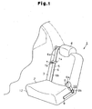
- a vehicle seat 1 is located in a passenger compartment of a vehicle (not shown). As shown in Figs. 1 and 2A , the seat 1 includes a seat portion 2 supporting the buttocks and thighs of the occupant P seated on the seat 1, a reclining backrest portion 3, a headrest 4 for supporting the head of the seated occupant P, and a seat belt 5.
- the seat belt 5 is a three-point seat belt and functions as a restrainer (restraining means) that restrains the occupant P seated on the seat 1 to the seat 1.
- the seat belt 5 includes a webbing 6, a tongue 7 attached to the webbing 6 to be movable along the longitudinal direction of the webbing 6, and buckle device 10 provided on a side of the seat 1.
- One end of the webbing 6 is fixed to the side of the seat 1 at which the buckle device 10 is not provided.
- the other end of the webbing 6 is wound by a seat belt retractor (not shown).
- the tongue 7 includes a sliding portion 7a and an engaging portion 7b.
- the tongue 7 is engaged with a buckle 8 of the buckle device 10 at the engaging portion 7b.
- the sliding portion 7a allows the webbing 6 to pass therethrough so that the tongue 7 slides on the webbing 6 at the sliding portion 7a.
- This configuration allows the occupant P to adjust the length of the webbing 6 that is drawn out of the seat belt retractor as necessary.
- the occupant P can slide the tongue 7 on the webbing 6 to adjust the length of a lap belt portion 6b of the webbing 6, which restrains the lumbar region of the occupant P, and a shoulder belt portion 6a of the webbing 6, which restrains the shoulder region of the occupant P.
- the lap belt portion 6b refers to a portion of the webbing 6 that extends from the end of the webbing fixed to the side of the seat 1 to the tongue 7, and the shoulder belt portion 6a refers to a portion of the webbing 6 that extends from the tongue 7 to the seat belt retractor.
- the buckle device 10 includes the box-like buckle 8 and a retainer 9 fixed to a side of the seat 1.
- the buckle 8 has an insertion opening 8a that allows insertion of the engaging portion 7b of the tongue 7.
- the buckle 8 is pivotably coupled to the retainer 9 at a coupling portion 8b provided at a position away from the insertion opening 8a. The buckle 8 is thus pivotable relative to the seat 1.
- the seat portion 2 includes a frame 11 and a cushion body 12 located on the frame 11.
- the frame 11 includes a pair of left and right support plates 13.
- the support plates 13 have a shape elongated along the front and rear direction.
- S springs 16 for supporting the cushion body 12 are suspended between the front rod 14 and the rear rod 15.
- a seat pan 17 shown in Fig. 2A is provided in a front portion of the space between the support plates 13.
- the seat pan 17 has an accommodation recess 17a extending along the vehicle width.
- An airbag apparatus 20 serving as an occupant protection apparatus is accommodated in the accommodation recess 17a.
- the airbag apparatus 20 will be discussed below.
- the seat portion 2 is covered with a cover 18 made of cloth or leather.
- the airbag apparatus 20 includes an inflator 21 serving as a gas generator and an inflatable airbag 22 made of cloth.
- the inflator 21 is shaped like a cylindrical column and is accommodated in a cylindrical case 21a while being wrapped with the airbag 22, such that the axis of the inflator 21 extends along the width of the vehicle.
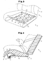
- the airbag 22, as shown in Fig. 4 is deployed and inflated between the cushion body 12 and the frame 11 (more specifically, between the cushion body 12 and the S springs 16), so as to expand over a portion (in this embodiment, a half) of the area of the seat portion 2 that contacts the thighs and the buttocks of the occupant P seated on the seat 1.
- the airbag 22 Prior to inflation, that is, when accommodated in the accommodation recess 17a, the airbag 22 is compactly folded. Specifically, a portion of the airbag 22 that is above the inflator 21 is folded in a bellows like manner, such that most part of the airbag 22 is deployed rearward when inflated.
- the airbag apparatus 20 includes a collision detection sensor 23 serving as a collision detection section (collision detection means) that detects a collision of the vehicle and a contact sensor 24 that senses whether the tongue 7 is in contact with (that is, engaged with) the buckle 8.
- a collision detection sensor 23 serving as a collision detection section (collision detection means) that detects a collision of the vehicle and a contact sensor 24 that senses whether the tongue 7 is in contact with (that is, engaged with) the buckle 8.
- an abnormal acceleration detection sensor serving as an abnormal acceleration detection section (abnormal acceleration detection means) that detects an abnormal acceleration may be used.
- the airbag apparatus 20 further includes an electronic control unit (ECU) 25 serving as a control section (control means) that controls the inflation of the airbag 22.
- the collision detection sensor 23 is connected to the ECU 25, and sends a collision signal to the ECU 25 when detecting a collision of the vehicle.
- the contact sensor 24 is also connected to the ECU 25, and sends a sensing signal to the ECU 25 when sensing that the tongue 7 is engaged with the buckle 8, or that the seat belt 5 is being used.
- the inflator 21 is also connected to the ECU 25. The operation of the inflator 21 is controlled through signals sent from the ECU 25.
- the ECU 25 determines whether the ECU 25 has received a sensing signal from the contact sensor 24. If the outcome of the determination is positive, that is, if a sensing signal from the contact sensor 24 has been received by the ECU 25, the ECU 25 outputs a control signal to activate the inflator 21 to the inflator 21. This activates the inflator 21 to send high pressure gas to the airbag 22. The gas in turn deploys and inflates the airbag 22. That is, if the ECU 25 has received a sensing signal from the contact sensor 24, the ECU 25 determines that an occupant P is seated on the seat 1 while using the seat belt 5. The ECU 25 then permits the airbag 22 to be inflated.
- the front half of the cushion body 12 is mainly pushed upward as shown in Fig. 4 .
- the lumbar region K of the occupant P on the seat 1 is moved upward so as to be pressed against the lap belt portion 6b.
- the lap belt portion 6b thus tightly restrains the occupant P on the seat 1. This prevents the "submarine phenomenon," in which the body of the occupant P on the seat 1 moves forward while sliding along the seat portion 2 of the seat 1 and through below the seat belt 5.
- the ECU 25 determines that no occupant is seated on the seat 1 or that an occupant P is seated on the seat 1 without using the seat belt 5, and inhibits the inflation of the airbag 22.
- the contact sensor 24 functions as a sensing section (sensing means) that senses whether an occupant P is seated on the seat 1.
- the contact sensor 24 also functions as a sensing section (sensing means) that senses whether an occupant P is seated on the seat 1 while being restrained to the seat 1 by the seat belt 5.
- the present comparative example provides the following advantages.
- the airbag apparatus 20 includes a weight sensor 30 instead of the contact sensor 24 as shown in Fig. 6 .
- the weight sensor 30 senses whether the weight on the seat 1 is not less than a predetermined value.
- the weight sensor 30 is connected to the ECU 25, and sends a sensing signal when sensing that the weight on the seat 1 is equal to or more than the predetermined value.
- the predetermined value is set to a value that enables the ECU 25 to determine whether the object on the seat is an article or a relatively light weighted occupant, and may be set to 20 kg.
- the ECU 25 determines whether the ECU 25 has received a sensing signal from the weight sensor 30. If the outcome of the determination is positive, that is, if a sensing signal from the weight sensor 30 has been received by the ECU 25, the ECU 25 outputs a control signal to activate the inflator 21 to the inflator 21. Contrastingly, if the outcome of the determination is negative, that is, if a sensing signal from the weight sensor 30 has not been received by the ECU 25, the ECU 25 does not output a control signal. That is, the ECU 25 does not activate the inflator 21.
- the weight sensor 30 functions as a sensing section (sensing means) that senses whether an occupant P is seated on the seat 1.
- the second comparative example provides the following advantages.
- the airbag apparatus 20 includes a weight sensor 30 in addition to the contact sensor 24 as shown in Fig. 7 .
- the weight sensor 30 senses whether the weight on the seat 1 is not less than a predetermined value.
- the weight sensor 30 is connected to the ECU 25, and sends a sensing signal when sensing that the weight on the seat 1 is equal to or more than the predetermined value.
- the predetermined value is set to a value that enables the ECU 25 to determine whether the object on the seat is an article or a relatively light weighted occupant, and may be set to 20 kg.
- the ECU 25 determines whether the ECU 25 has received a sensing signal from the weight sensor 30. If the outcome of the determination is negative, that is, if a sensing signal from the weight sensor 30 has not been received by the ECU 25, the ECU 25 does not output a control signal to activate the inflator 21. That is, the ECU 25 does not activate the inflator 21.
- the ECU 25 continuously detects whether a sensing signal from the contact sensor 24 has been received by the ECU 25.
- the ECU 25 If the outcome of the determination is positive, that is, if a sensing signal from the contact sensor 24 has been received by the ECU 25, the ECU 25 outputs the control signal to the inflator 21 so that the airbag 22 is inflated. On the other hand, when the outcome of the determination whether a sensing signal from the contact sensor 24 has been received by the ECU 25 is negative, that is, when the sensing signal from the contact sensor 24 has not been received by the ECU 25, the ECU 25 does not output the control signal. That is, the ECU 25 does not activate the inflator 21.
- the weight sensor 30 functions as a sensing section (sensing means) that senses whether an occupant P is seated on the seat 1.
- the contact sensor 24 functions as a sensing section (sensing means) that senses whether an occupant P is seated on the seat 1 while being restrained to the seat 1 by the seat belt 5.
- the embodiment provides the following advantage.
- the ECU 25 determines whether an occupant P is seated on the seat 1 while using the seat belt 5 based on whether a sensing signal has been sent from the contact sensor 24. Even if a sensing signal has been sent from the weight sensor 30, the ECU 25 does not activate the inflator 21 as long as no sensing signal has been sent from the contact sensor 24, thereby inhibiting the inflation of the airbag 22 at a vehicle collision. Therefore, when an occupant P is seated on the seat 1 without using the seat belt 5, the inflation of the airbag 22 is inhibited at a vehicle collision.
- the embodiment may be modified as follows.
- the weight sensor 30 is used as a sensing section (sensing means) for sensing whether an occupant P is seated on the seat 1.
- a pressure sensor that senses whether the load (pressure) acting on the seat 1 is equal to or more than a predetermined value may be used.
- an infrared sensor that senses the temperature of an object on the seat 1 may be used. To more accurately execute the detection whether an occupant P is seated on the seat 1, at least one of a pressure sensor and an infrared sensor may be used together with the weight sensor 30.
- the airbag 22 may be deployed and inflated in such a manner as to expand over the entire region of the seat portion 2 that contacts the thighs and buttocks of the occupant P seated on the seat 1.
- the airbag 22 When the airbag 22 is inflated, the cushion body 12 is substantially entirely pushed upward. In this case, the impact applied to the occupant P on the seat 1 due to the inflation of the airbag 22 is widely dispersed.
- the airbag apparatus 20 may be provided in a rear portion of the seat 1.
- the airbag 22 is configured to be deployed forward when inflated.
- the collision detection sensor 23 may be replaced by a collision prediction sensor.
- the collision prediction sensor sends a sensing signal to the ECU 25.
- the ECU 25 determines whether to permit the inflation of the airbag 22.
- the restraint of the occupant P may be sensed by a sensor that senses whether the webbing 6 is drawn out of the seat belt retractor.
- An occupant protection apparatus (20) includes an airbag (22) provided at a seat portion (2) of a vehicle seat (1).
- the airbag (22) is inflatable in such manner as to push up at least a part of a cushion body (12) of the seat portion (2).
- an ECU (25) permits inflation of the airbag (22) if a sensor (24) senses that an occupant (P) is seated on the seat (1), and inhibits inflation of the airbag (22) if the sensor (24) senses that no occupant is seated on the seat (1). Therefore, when no occupant is seated on the seat (1), inflation of the airbag (22) is inhibited at a vehicle collision.
Landscapes
- Engineering & Computer Science (AREA)
- Mechanical Engineering (AREA)
- Air Bags (AREA)
- Seats For Vehicles (AREA)
Description
- The present invention relates to an apparatus and a method for protecting an occupant of a vehicle such as an automobile in a collision.
- When an impact due to a collision is applied from front, the body of the occupant on the seat can move forward while sliding along the seat portion of the seat and through below the seat belt. This is known as a "submarine phenomenon."
-
Japanese Laid-Open Utility Model Publication No. 2-21134 -
European patent application EP 1 422 104 A1 (Preamble of claim 1) discloses an airbag similar to the above. - Document
DE 40 08 243 A1 discloses an airbag in a seat cushion and a passenger detection. The airbag is intended to protect a passenger seated on a seat in a passenger compartment of a vehicle. The airbag is provided to the rear surface of the seat being located in front of the passenger to be protected. Further, the presence of a passenger on the respective seat is either detected by a load detector provided in the seat or by a buckle contact. - However, if the seated occupant is not using the seat belt, the cushion member can toss up the seated occupant when being pushed up at the time of collision. This is more likely to occur when the weight of the occupant is light. Also, if no occupant is seated and an article is placed on the seat instead, the article may be tossed up by the cushion member when the cushion member is pushed up at the time of collision.
- Accordingly, it is an objective of the present invention to provide an occupant protection apparatus and method that, when no occupant is seated and an article is placed on a seat, inhibit the inflation of a bag such as an airbag. Another objective of the present invention is to provide an occupant protection apparatus and method that, when a occupant seated on the seat is not restrained in the seat, inhibit the inflation of an airbag.
- To achieve the foregoing objective and in accordance with a first aspect of the present invention, an apparatus according to claim 1 and a method according to
claim 4 is provided. - Other aspects and advantages of the invention will become apparent from the following description, taken in conjunction with the accompanying drawings, illustrating by way of example the principles of the invention.
- The invention, together with objects and advantages thereof, may best be understood by reference to the following description of the presently preferred embodiments together with the accompanying drawings in which:
-
Fig. 1 is a perspective view illustrating a vehicle seat in which an airbag apparatus according to a first comparative example is installed not belonging to the present invention; -
Fig. 2A is a side cross-sectional view illustrating the seat ofFig. 1 ; -
Fig. 2B is an enlarged view illustrating the airbag apparatus shown inFig. 2A ; -
Fig. 3 is a perspective view illustrating the frame of the seat shown inFig. 1 ; -
Fig. 4 is a side cross-sectional view illustrating the seat shown inFig. 1 , when the airbag is inflated; -
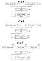
Fig. 5 is a block diagram showing the configuration of the airbag apparatus of the first comparative example not belonging to the invention; -
Fig. 6 is a block diagram showing the configuration of an airbag apparatus according to a second comparative example not belonging to the present invention; and -
Fig. 7 is a block diagram showing the configuration of an airbag apparatus according to an embodiment of the present invention. - A first comparative example will now be described with reference to
Figs. 1 to 5 . In the following, the traveling direction of the vehicle is defined as a forward direction. With reference to the forward direction, front and rear, up and down, and left and right directions are defined. Regarding a vehicle seat, front and rear, up and down, and left and right directions are defined with reference to a state in which the seat is installed in the vehicle. - A vehicle seat 1 is located in a passenger compartment of a vehicle (not shown). As shown in
Figs. 1 and2A , the seat 1 includes aseat portion 2 supporting the buttocks and thighs of the occupant P seated on the seat 1, a recliningbackrest portion 3, aheadrest 4 for supporting the head of the seated occupant P, and aseat belt 5. - The
seat belt 5 is a three-point seat belt and functions as a restrainer (restraining means) that restrains the occupant P seated on the seat 1 to the seat 1. Specifically, theseat belt 5 includes awebbing 6, atongue 7 attached to thewebbing 6 to be movable along the longitudinal direction of thewebbing 6, andbuckle device 10 provided on a side of the seat 1. One end of thewebbing 6 is fixed to the side of the seat 1 at which thebuckle device 10 is not provided. The other end of thewebbing 6 is wound by a seat belt retractor (not shown). Thetongue 7 includes a slidingportion 7a and an engaging portion 7b. Thetongue 7 is engaged with abuckle 8 of thebuckle device 10 at the engaging portion 7b. The slidingportion 7a allows thewebbing 6 to pass therethrough so that thetongue 7 slides on thewebbing 6 at the slidingportion 7a. - This configuration allows the occupant P to adjust the length of the
webbing 6 that is drawn out of the seat belt retractor as necessary. The occupant P can slide thetongue 7 on thewebbing 6 to adjust the length of alap belt portion 6b of thewebbing 6, which restrains the lumbar region of the occupant P, and ashoulder belt portion 6a of thewebbing 6, which restrains the shoulder region of the occupant P. Thelap belt portion 6b refers to a portion of thewebbing 6 that extends from the end of the webbing fixed to the side of the seat 1 to thetongue 7, and theshoulder belt portion 6a refers to a portion of thewebbing 6 that extends from thetongue 7 to the seat belt retractor. - The
buckle device 10 includes the box-like buckle 8 and aretainer 9 fixed to a side of the seat 1. Thebuckle 8 has an insertion opening 8a that allows insertion of the engaging portion 7b of thetongue 7. Thebuckle 8 is pivotably coupled to theretainer 9 at acoupling portion 8b provided at a position away from the insertion opening 8a. Thebuckle 8 is thus pivotable relative to the seat 1. - As shown in
Fig. 2A , theseat portion 2 includes aframe 11 and acushion body 12 located on theframe 11. As shown inFig. 3 , theframe 11 includes a pair of left andright support plates 13. Thesupport plates 13 have a shape elongated along the front and rear direction. Afront rod 14 and arear rod 15, which extend along the vehicle width (along the left and right direction), bridge over thesupport plates 13.S springs 16 for supporting thecushion body 12 are suspended between thefront rod 14 and therear rod 15. - In a front portion of the space between the
support plates 13, aseat pan 17 shown inFig. 2A is provided. Theseat pan 17 has an accommodation recess 17a extending along the vehicle width. Anairbag apparatus 20 serving as an occupant protection apparatus is accommodated in theaccommodation recess 17a. Theairbag apparatus 20 will be discussed below. Theseat portion 2 is covered with acover 18 made of cloth or leather. - As shown in
Fig. 2B , theairbag apparatus 20 includes an inflator 21 serving as a gas generator and aninflatable airbag 22 made of cloth. The inflator 21 is shaped like a cylindrical column and is accommodated in a cylindrical case 21a while being wrapped with theairbag 22, such that the axis of the inflator 21 extends along the width of the vehicle. - The
airbag 22, as shown inFig. 4 , is deployed and inflated between thecushion body 12 and the frame 11 (more specifically, between thecushion body 12 and the S springs 16), so as to expand over a portion (in this embodiment, a half) of the area of theseat portion 2 that contacts the thighs and the buttocks of the occupant P seated on the seat 1. Prior to inflation, that is, when accommodated in theaccommodation recess 17a, theairbag 22 is compactly folded. Specifically, a portion of theairbag 22 that is above theinflator 21 is folded in a bellows like manner, such that most part of theairbag 22 is deployed rearward when inflated. - As shown in
Fig. 5 , theairbag apparatus 20 includes acollision detection sensor 23 serving as a collision detection section (collision detection means) that detects a collision of the vehicle and acontact sensor 24 that senses whether thetongue 7 is in contact with (that is, engaged with) thebuckle 8. Instead of thecollision detection sensor 23, an abnormal acceleration detection sensor serving as an abnormal acceleration detection section (abnormal acceleration detection means) that detects an abnormal acceleration may be used. Theairbag apparatus 20 further includes an electronic control unit (ECU) 25 serving as a control section (control means) that controls the inflation of theairbag 22. Thecollision detection sensor 23 is connected to theECU 25, and sends a collision signal to theECU 25 when detecting a collision of the vehicle. Thecontact sensor 24 is also connected to theECU 25, and sends a sensing signal to theECU 25 when sensing that thetongue 7 is engaged with thebuckle 8, or that theseat belt 5 is being used. The inflator 21 is also connected to theECU 25. The operation of the inflator 21 is controlled through signals sent from theECU 25. - The operation of the
airbag apparatus 20 will now be described. - When receiving a collision signal from the
collision detection sensor 23, theECU 25 determines whether theECU 25 has received a sensing signal from thecontact sensor 24. If the outcome of the determination is positive, that is, if a sensing signal from thecontact sensor 24 has been received by theECU 25, theECU 25 outputs a control signal to activate the inflator 21 to theinflator 21. This activates the inflator 21 to send high pressure gas to theairbag 22. The gas in turn deploys and inflates theairbag 22. That is, if theECU 25 has received a sensing signal from thecontact sensor 24, theECU 25 determines that an occupant P is seated on the seat 1 while using theseat belt 5. TheECU 25 then permits theairbag 22 to be inflated. - When the
airbag 22 is thus inflated, the front half of thecushion body 12 is mainly pushed upward as shown inFig. 4 . As a result, the lumbar region K of the occupant P on the seat 1 is moved upward so as to be pressed against thelap belt portion 6b. Thelap belt portion 6b thus tightly restrains the occupant P on the seat 1. This prevents the "submarine phenomenon," in which the body of the occupant P on the seat 1 moves forward while sliding along theseat portion 2 of the seat 1 and through below theseat belt 5. - On the other hand, when the outcome of the determination whether a sensing signal from the
contact sensor 24 has been received by theECU 25 is negative, that is, when the sensing signal from thecontact sensor 24 has not been received by theECU 25, theECU 25 does not outputs the control signal. Therefore, theinflator 21 is not activated. That is, when receiving no sensing signal from thecontact sensor 24, theECU 25 determines that no occupant is seated on the seat 1 or that an occupant P is seated on the seat 1 without using theseat belt 5, and inhibits the inflation of theairbag 22. In this embodiment, thecontact sensor 24 functions as a sensing section (sensing means) that senses whether an occupant P is seated on the seat 1. Thecontact sensor 24 also functions as a sensing section (sensing means) that senses whether an occupant P is seated on the seat 1 while being restrained to the seat 1 by theseat belt 5. - The present comparative example provides the following advantages.
- (1) When the
contact sensor 24 senses that thetongue 7 of theseat belt 5 is engaged with thebuckle 8, theECU 25 determines that an occupant P is seated on the seat 1 while using theseat belt 5. In this case, theECU 25 activates the inflator 21, thereby permitting theairbag 22 to be inflated at the time of a vehicle collision. When theairbag 22 is inflated, thecushion body 12 is pushed upward. As a result, the lumbar region K of the occupant P on the seat 1 is moved upward so as to be pressed against thelap belt portion 6b. Thelap belt portion 6b thus tightly restrains the occupant P on the seat 1. This suppresses the submarine phenomenon. - (2) On the other hand, when receiving no sensing signal from the
contact sensor 24, theECU 25 determines that no occupant is seated on the seat 1 or that an occupant P is seated on the seat 1 without using theseat belt 5. In this case, theECU 25 does not activate the inflator 21, thereby inhibiting theairbag 22 from being inflated at the time of a vehicle collision. Thus, when no occupant is seated on the seat 1 and an article is placed on the seat 1 instead, or when an occupant P is seated on the seat 1 without using theseat belt 5, the inflation of theairbag 22 at the time of a vehicle collision is inhibited. - A second comparative example will now be described. Like or the same reference numerals are given to those components that are like or the same as the corresponding components of the first comparative example, and detailed explanations and drawings are omitted or simplified.
- In the second comparative example, the
airbag apparatus 20 includes aweight sensor 30 instead of thecontact sensor 24 as shown inFig. 6 . Theweight sensor 30 senses whether the weight on the seat 1 is not less than a predetermined value. Theweight sensor 30 is connected to theECU 25, and sends a sensing signal when sensing that the weight on the seat 1 is equal to or more than the predetermined value. The predetermined value is set to a value that enables theECU 25 to determine whether the object on the seat is an article or a relatively light weighted occupant, and may be set to 20 kg. - When receiving a collision signal from the
collision detection sensor 23, theECU 25 determines whether theECU 25 has received a sensing signal from theweight sensor 30. If the outcome of the determination is positive, that is, if a sensing signal from theweight sensor 30 has been received by theECU 25, theECU 25 outputs a control signal to activate the inflator 21 to theinflator 21. Contrastingly, if the outcome of the determination is negative, that is, if a sensing signal from theweight sensor 30 has not been received by theECU 25, theECU 25 does not output a control signal. That is, theECU 25 does not activate theinflator 21. In the second embodiment, theweight sensor 30 functions as a sensing section (sensing means) that senses whether an occupant P is seated on the seat 1. - The second comparative example provides the following advantages.
- (3) When receiving no sensing signal from the
weight sensor 30, theECU 25 determines that a relatively light weighted occupant P is seated on the seat 1 or an article is placed on the seat 1. In this case, theECU 25 does not activate the inflator 21, thereby inhibiting theairbag 22 from being inflated at the time of a vehicle collision. Thus, when no occupant is seated on the seat 1 and an article is placed on the seat 1 instead, or when the occupant P seated on the seat 1 is relatively light-weighted, the inflation of theairbag 22 at the time of a vehicle collision is inhibited. - (4) On the other hand, when an article is placed on the seat 1, if the weight of the article is relatively great, the article is unlikely to be tossed upward when the
cushion body 12 is pushed upward at a vehicle collision. Also, when an occupant P is seated on the seat 1 without using theseat belt 5, if the weight of the occupant P is relatively great, the occupant P is unlikely to be tossed upward when thecushion body 12 is pushed upward at a vehicle collision. Thus, when the weight on the seat 1 is not less than the predetermined value, theECU 25 permits theairbag 22 to be inflated at the time of a vehicle collision. When theairbag 22 is inflated, thecushion body 12 is pushed upward. As a result, the lumbar region K of the occupant P on the seat 1 is moved upward so as to be pressed against thelap belt portion 6b. Thelap belt portion 6b thus tightly restrains the occupant P on the seat 1. This suppresses the submarine phenomenon. - An embodiment of the present invention will now be described. Like or the same reference numerals are given to those components that are like or the same as the corresponding components of the first comparative example, and detailed explanations and drawings are omitted or simplified.
- In the embodiment, the
airbag apparatus 20 includes aweight sensor 30 in addition to thecontact sensor 24 as shown inFig. 7 . Theweight sensor 30 senses whether the weight on the seat 1 is not less than a predetermined value. Theweight sensor 30 is connected to theECU 25, and sends a sensing signal when sensing that the weight on the seat 1 is equal to or more than the predetermined value. The predetermined value is set to a value that enables theECU 25 to determine whether the object on the seat is an article or a relatively light weighted occupant, and may be set to 20 kg. - When receiving a collision signal from the
collision detection sensor 23, theECU 25 determines whether theECU 25 has received a sensing signal from theweight sensor 30. If the outcome of the determination is negative, that is, if a sensing signal from theweight sensor 30 has not been received by theECU 25, theECU 25 does not output a control signal to activate theinflator 21. That is, theECU 25 does not activate theinflator 21. - On the other hand, when the outcome of the determination whether a sensing signal from the
weight sensor 30 has been received by theECU 25 is positive, that is, when the sensing signal from theweight sensor 30 has been received by theECU 25, theECU 25 continuously detects whether a sensing signal from thecontact sensor 24 has been received by theECU 25. - If the outcome of the determination is positive, that is, if a sensing signal from the
contact sensor 24 has been received by theECU 25, theECU 25 outputs the control signal to the inflator 21 so that theairbag 22 is inflated. On the other hand, when the outcome of the determination whether a sensing signal from thecontact sensor 24 has been received by theECU 25 is negative, that is, when the sensing signal from thecontact sensor 24 has not been received by theECU 25, theECU 25 does not output the control signal. That is, theECU 25 does not activate theinflator 21. In the third embodiment, theweight sensor 30 functions as a sensing section (sensing means) that senses whether an occupant P is seated on the seat 1. Thecontact sensor 24 functions as a sensing section (sensing means) that senses whether an occupant P is seated on the seat 1 while being restrained to the seat 1 by theseat belt 5. - In addition to the item (1) of the advantages of the first comparative example, the embodiment provides the following advantage.
- (5) At a vehicle collision, the
ECU 25 determines whether the weight on the seat 1 is equal to or more than the predetermined value based on whether a sensing signal has been sent from theweight sensor 30. When receiving no sensing signal from theweight sensor 30, theECU 25 determines that a relatively light weighted occupant P is seated on the seat 1 or an article is placed on the seat 1. In this case, theECU 25 does not activate the inflator 21, thereby inhibiting theairbag 22 from being inflated at the time of a vehicle collision. Thus, when no occupant is seated on the seat 1 and an article is placed on the seat 1 instead, or when the occupant P seated on the seat 1 is relatively light-weighted, the inflation of theairbag 22 at the time of a vehicle collision is inhibited. - Subsequent to the determination whether the weight on the seat 1 is equal to or more than the predetermined value, the
ECU 25 determines whether an occupant P is seated on the seat 1 while using theseat belt 5 based on whether a sensing signal has been sent from thecontact sensor 24. Even if a sensing signal has been sent from theweight sensor 30, theECU 25 does not activate the inflator 21 as long as no sensing signal has been sent from thecontact sensor 24, thereby inhibiting the inflation of theairbag 22 at a vehicle collision. Therefore, when an occupant P is seated on the seat 1 without using theseat belt 5, the inflation of theairbag 22 is inhibited at a vehicle collision. - The embodiment may be modified as follows.
- In the embodiment, the
weight sensor 30 is used as a sensing section (sensing means) for sensing whether an occupant P is seated on the seat 1. However, instead of theweight sensor 30, a pressure sensor that senses whether the load (pressure) acting on the seat 1 is equal to or more than a predetermined value may be used. Alternatively, an infrared sensor that senses the temperature of an object on the seat 1 may be used. To more accurately execute the detection whether an occupant P is seated on the seat 1, at least one of a pressure sensor and an infrared sensor may be used together with theweight sensor 30. - The
airbag 22 may be deployed and inflated in such a manner as to expand over the entire region of theseat portion 2 that contacts the thighs and buttocks of the occupant P seated on the seat 1. When theairbag 22 is inflated, thecushion body 12 is substantially entirely pushed upward. In this case, the impact applied to the occupant P on the seat 1 due to the inflation of theairbag 22 is widely dispersed. - Instead of being provided at a front portion of the seat 1, the
airbag apparatus 20 may be provided in a rear portion of the seat 1. In this case, theairbag 22 is configured to be deployed forward when inflated. - The
collision detection sensor 23 may be replaced by a collision prediction sensor. When prediction a collision of the vehicle, the collision prediction sensor sends a sensing signal to theECU 25. When receiving the sensing signal from the collision prediction sensor, theECU 25 determines whether to permit the inflation of theairbag 22. - Whether the occupant P on the seat 1 is restrained to the seat 1 by the
seat belt 5 does not need to be sensed by thecontact sensor 24. For example, the restraint of the occupant P may be sensed by a sensor that senses whether thewebbing 6 is drawn out of the seat belt retractor. - An occupant protection apparatus (20) includes an airbag (22) provided at a seat portion (2) of a vehicle seat (1). The airbag (22) is inflatable in such manner as to push up at least a part of a cushion body (12) of the seat portion (2). At the time of collision of the vehicle, an ECU (25) permits inflation of the airbag (22) if a sensor (24) senses that an occupant (P) is seated on the seat (1), and inhibits inflation of the airbag (22) if the sensor (24) senses that no occupant is seated on the seat (1). Therefore, when no occupant is seated on the seat (1), inflation of the airbag (22) is inhibited at a vehicle collision.
Claims (6)
- An apparatus for protecting an occupant (P) of a vehicle, the vehicle having a seat (1), wherein the seat (1) includes a seat portion (2) having a cushion body (12), the apparatus includes an airbag (22) provided at the seat portion (2), the airbag (22) being inflatable in such manner as to push up at least a part of the.cushion body (12) of the seat portion (2), the apparatus
characterized by:first sensing means (30) that senses whether an occupant (P) is seated on the seat (1); andrestraining means (5) that restrains an occupant (P) seated on the seat (1) to the seat (1);second sensing means (24) that senses whether the restraining means (5) is in operation;control means (25) that controls whether to inflate the airbag (22), wherein, when a collision of the vehicle has occurred or is predicted, the control means (25) permits inflation of the airbag (22) if the first sensing means (30) senses that an occupant (P) is seated on the seat (1) and the second sensing means (24) senses that the restraining means (5) is in operation, and inhibits inflation of the airbag (22) if the first sensing means (30) senses that no occupant is seated on the seat (1) or if the second sensing means (24) senses that the restraining means (5) is not in operation. - The apparatus according to claim 1,
characterized in that
the first sensing means (30) senses whether an occupant (P) is seated on the seat (1) based on whether a weight on the seat (1) is equal to or more than a predetermined value. - The apparatus according to claim 1 or 2,
characterized in that
the restraining means (5) is a seat belt having a tongue (7) and a buckle (8), and wherein the second sensing means (24) senses whether the restraining means (5) is in operation based on whether the tongue (7) is engaged with the buckle (8). - A method for protecting an occupant (P) of a vehicle, the vehicle having a seat (1), wherein the seat (1) includes a seat portion (2) having a cushion body (12), an airbag (22) being provided at the seat portion (2), wherein the airbag (22) is inflatable in such manner as to push up at least a part of the cushion body (12) of the seat portion (2), the method
characterized by:sensing, when a collision of the vehicle has occurred or is predicted, whether an occupant (P) is seated on the seat (1);sensing, when a collision of the vehicle has occurred or is predicted, whether restraining means (5) that restrains an occupant (P) seated on the seat (1) to the seat (1) is in operation; andselectively permitting and inhibiting inflation of the airbag (22), wherein, when it is sensed that an occupant (P) is seated on the seat (1) and that the restraining means (5) is in operation, inflation of the airbag (22) is permitted, and wherein, when it is sensed that no occupant is seated on the seat (1) or when it is sensed that the restraining means (5) is not in operation, inflation of the airbag (22) is inhibited. - The method according to claim 4,
characterized in that
whether an occupant (P) is seated on the seat (1) is sensed based on whether a weight on the seat (1) is equal to or more than a predetermined value. - The method according to claim 4 or 5,
characterized in that
the restraining means (5) is a seat belt having a tongue (7) and a buckle (8), and wherein whether the restraining means (5) is in operation is sensed based on whether the tongue (7) is engaged with the buckle (8).
Applications Claiming Priority (1)
| Application Number | Priority Date | Filing Date | Title |
|---|---|---|---|
| JP2006181721A JP2008007036A (en) | 2006-06-30 | 2006-06-30 | Crew protection device |
Publications (2)
| Publication Number | Publication Date |
|---|---|
| EP1873022A1 EP1873022A1 (en) | 2008-01-02 |
| EP1873022B1 true EP1873022B1 (en) | 2009-04-15 |
Family
ID=38541942
Family Applications (1)
| Application Number | Title | Priority Date | Filing Date |
|---|---|---|---|
| EP07111173A Not-in-force EP1873022B1 (en) | 2006-06-30 | 2007-06-27 | Occupant protection apparatus and method |
Country Status (5)
| Country | Link |
|---|---|
| US (1) | US20080001446A1 (en) |
| EP (1) | EP1873022B1 (en) |
| JP (1) | JP2008007036A (en) |
| CN (1) | CN101096196A (en) |
| DE (1) | DE602007000892D1 (en) |
Families Citing this family (15)
| Publication number | Priority date | Publication date | Assignee | Title |
|---|---|---|---|---|
| US20110017298A1 (en) * | 2007-11-14 | 2011-01-27 | Stion Corporation | Multi-junction solar cell devices |
| WO2011024202A2 (en) * | 2009-08-31 | 2011-03-03 | Tata Consultancy Services Ltd. | Passive collision sensing and protection system |
| TW201136784A (en) * | 2010-04-21 | 2011-11-01 | Hon Hai Prec Ind Co Ltd | Automobile seat system |
| CN102874143B (en) * | 2012-06-13 | 2015-05-13 | 浙江吉利汽车研究院有限公司杭州分公司 | Control method of automobile seat adjusting controller |
| JP5613743B2 (en) * | 2012-10-05 | 2014-10-29 | シロキ工業株式会社 | Slide rail device for vehicle |
| US10632951B2 (en) * | 2017-03-14 | 2020-04-28 | Ford Global Technologies, Llc | Impact absorbing system |
| US10486562B2 (en) * | 2017-09-07 | 2019-11-26 | Nissan North America, Inc. | Anti-submarining seat structure |
| JP6677951B2 (en) * | 2018-03-30 | 2020-04-08 | 株式会社Subaru | Occupant protection device |
| JP2020055481A (en) * | 2018-10-03 | 2020-04-09 | トヨタ自動車株式会社 | Vehicular seat |
| CN110497872A (en) * | 2019-05-31 | 2019-11-26 | 浙江众泰汽车制造有限公司 | Automobile passenger neck protecting device and its control method |
| JP7107892B2 (en) * | 2019-06-12 | 2022-07-27 | トヨタ自動車株式会社 | vehicle seat |
| CN110654283A (en) * | 2019-10-15 | 2020-01-07 | 江苏理工学院 | An intelligently adjustable car seat |
| JP7431112B2 (en) | 2020-06-12 | 2024-02-14 | トヨタ自動車株式会社 | vehicle seat |
| US11648901B1 (en) * | 2022-02-02 | 2023-05-16 | Zoox, Inc. | Occupant protection system |
| CN115071629A (en) * | 2022-06-27 | 2022-09-20 | 中国第一汽车股份有限公司 | Front constraint system maintenance economical point explosion method |
Family Cites Families (5)
| Publication number | Priority date | Publication date | Assignee | Title |
|---|---|---|---|---|
| DE4008243A1 (en) | 1990-03-15 | 1991-09-19 | Diehl Gmbh & Co | Airbag protection for passenger vehicle - has shaped cushion expanded out of rear structure of seat to protect rear passenger |
| JP4135480B2 (en) | 2002-11-21 | 2008-08-20 | タカタ株式会社 | Crew protection device |
| DE102005041389A1 (en) * | 2005-02-23 | 2006-09-28 | Acts Advanced Car Technology Systems Gmbh & Co.Kg | Occupant restraint system for motor vehicle, has belt monitoring units to indicate or forecast impact of belt with collision, and control unit has decision-making units to control adjusting units depending upon signal from monitoring units |
| JP4961902B2 (en) * | 2005-12-01 | 2012-06-27 | 豊田合成株式会社 | Crew protection device |
| DE102005059997B4 (en) * | 2005-12-13 | 2009-01-29 | Autoliv Development Ab | safety device |
-
2006
- 2006-06-30 JP JP2006181721A patent/JP2008007036A/en active Pending
-
2007
- 2007-06-26 US US11/819,330 patent/US20080001446A1/en not_active Abandoned
- 2007-06-26 CN CNA2007101094684A patent/CN101096196A/en active Pending
- 2007-06-27 EP EP07111173A patent/EP1873022B1/en not_active Not-in-force
- 2007-06-27 DE DE602007000892T patent/DE602007000892D1/en not_active Expired - Fee Related
Also Published As
| Publication number | Publication date |
|---|---|
| DE602007000892D1 (en) | 2009-05-28 |
| CN101096196A (en) | 2008-01-02 |
| EP1873022A1 (en) | 2008-01-02 |
| US20080001446A1 (en) | 2008-01-03 |
| JP2008007036A (en) | 2008-01-17 |
Similar Documents
| Publication | Publication Date | Title |
|---|---|---|
| EP1873022A1 (en) | Occupant protection apparatus and method | |
| JP4569684B2 (en) | Vehicle occupant restraint system | |
| JP5582292B2 (en) | Vehicle occupant protection device | |
| JP2781745B2 (en) | A device for preventing the operation of a vehicle occupant restraint system | |
| US6705641B2 (en) | Inflatable seat belt system | |
| EP0825070B1 (en) | Air bag apparatus for a passenger seat | |
| EP2799290B1 (en) | Head restraint system | |
| JP5942969B2 (en) | Front seat airbag system | |
| US7600777B2 (en) | Side airbag apparatus | |
| JP5675436B2 (en) | Airbag device | |
| CN111806384A (en) | Seat safety air bag | |
| US7108280B2 (en) | Vehicle occupant protection system | |
| JP7408507B2 (en) | Occupant protection device | |
| KR20170131129A (en) | Air bag device for car | |
| JP2017190045A (en) | Occupant protection device | |
| KR20170131130A (en) | Center air bag device and control method thereof | |
| US20200055479A1 (en) | Vehicle occupant restraint device and method for operating a vehicle occupant restraint device | |
| JP7168496B2 (en) | passenger protection device | |
| JP4161482B2 (en) | Crew protection device | |
| US12576758B2 (en) | Shoulder airbag and method of controlling deployment thereof | |
| JP4156532B2 (en) | Crew restraint system | |
| JP4917323B2 (en) | Crew protection device | |
| KR102361013B1 (en) | System for protecting the occupant's neck when a vehicle crash from behind | |
| JP2010247661A (en) | Crew protection device | |
| JP7408508B2 (en) | Occupant protection device |
Legal Events
| Date | Code | Title | Description |
|---|---|---|---|
| PUAI | Public reference made under article 153(3) epc to a published international application that has entered the european phase |
Free format text: ORIGINAL CODE: 0009012 |
|
| 17P | Request for examination filed |
Effective date: 20070627 |
|
| AK | Designated contracting states |
Kind code of ref document: A1 Designated state(s): AT BE BG CH CY CZ DE DK EE ES FI FR GB GR HU IE IS IT LI LT LU LV MC MT NL PL PT RO SE SI SK TR |
|
| AX | Request for extension of the european patent |
Extension state: AL BA HR MK YU |
|
| GRAP | Despatch of communication of intention to grant a patent |
Free format text: ORIGINAL CODE: EPIDOSNIGR1 |
|
| AKX | Designation fees paid |
Designated state(s): DE FR GB |
|
| GRAS | Grant fee paid |
Free format text: ORIGINAL CODE: EPIDOSNIGR3 |
|
| RIN1 | Information on inventor provided before grant (corrected) |
Inventor name: MIKUTSU, SATOSHI Inventor name: SUZUKI, SHIGEYUKI,C/O TOYODA GOSEI CO., LTD. Inventor name: OGUCHI, SHINJI,C/O TOYODA GOSEI CO., LTD. Inventor name: KAKUMU, MICHINORI |
|
| GRAA | (expected) grant |
Free format text: ORIGINAL CODE: 0009210 |
|
| RAP1 | Party data changed (applicant data changed or rights of an application transferred) |
Owner name: TOYOTA JIDOSHA KABUSHIKI KAISHA Owner name: TOYODA GOSEI CO., LTD. |
|
| AK | Designated contracting states |
Kind code of ref document: B1 Designated state(s): DE FR GB |
|
| REG | Reference to a national code |
Ref country code: GB Ref legal event code: FG4D |
|
| REF | Corresponds to: |
Ref document number: 602007000892 Country of ref document: DE Date of ref document: 20090528 Kind code of ref document: P |
|
| PGFP | Annual fee paid to national office [announced via postgrant information from national office to epo] |
Ref country code: FR Payment date: 20090618 Year of fee payment: 3 |
|
| PGFP | Annual fee paid to national office [announced via postgrant information from national office to epo] |
Ref country code: DE Payment date: 20090630 Year of fee payment: 3 |
|
| PLBE | No opposition filed within time limit |
Free format text: ORIGINAL CODE: 0009261 |
|
| STAA | Information on the status of an ep patent application or granted ep patent |
Free format text: STATUS: NO OPPOSITION FILED WITHIN TIME LIMIT |
|
| 26N | No opposition filed |
Effective date: 20100118 |
|
| REG | Reference to a national code |
Ref country code: FR Ref legal event code: ST Effective date: 20110228 |
|
| PG25 | Lapsed in a contracting state [announced via postgrant information from national office to epo] |
Ref country code: DE Free format text: LAPSE BECAUSE OF NON-PAYMENT OF DUE FEES Effective date: 20110101 |
|
| PG25 | Lapsed in a contracting state [announced via postgrant information from national office to epo] |
Ref country code: FR Free format text: LAPSE BECAUSE OF NON-PAYMENT OF DUE FEES Effective date: 20100630 |
|
| GBPC | Gb: european patent ceased through non-payment of renewal fee |
Effective date: 20110627 |
|
| PG25 | Lapsed in a contracting state [announced via postgrant information from national office to epo] |
Ref country code: GB Free format text: LAPSE BECAUSE OF NON-PAYMENT OF DUE FEES Effective date: 20110627 |