EP1872737A2 - Computergestütztes orthopädisch-chirurgisches System - Google Patents
Computergestütztes orthopädisch-chirurgisches System Download PDFInfo
- Publication number
- EP1872737A2 EP1872737A2 EP07252633A EP07252633A EP1872737A2 EP 1872737 A2 EP1872737 A2 EP 1872737A2 EP 07252633 A EP07252633 A EP 07252633A EP 07252633 A EP07252633 A EP 07252633A EP 1872737 A2 EP1872737 A2 EP 1872737A2
- Authority
- EP
- European Patent Office
- Prior art keywords
- camera
- image
- registration pointer
- pointer
- registration
- Prior art date
- Legal status (The legal status is an assumption and is not a legal conclusion. Google has not performed a legal analysis and makes no representation as to the accuracy of the status listed.)
- Granted
Links
- 238000012829 orthopaedic surgery Methods 0.000 title claims abstract description 23
- 210000000988 bone and bone Anatomy 0.000 claims abstract description 43
- 238000000034 method Methods 0.000 claims description 30
- 238000001356 surgical procedure Methods 0.000 claims description 23
- 230000004044 response Effects 0.000 claims description 7
- 239000010453 quartz Substances 0.000 claims description 4
- VYPSYNLAJGMNEJ-UHFFFAOYSA-N silicon dioxide Inorganic materials O=[Si]=O VYPSYNLAJGMNEJ-UHFFFAOYSA-N 0.000 claims description 4
- 239000013078 crystal Substances 0.000 claims description 2
- 238000004891 communication Methods 0.000 description 45
- 210000003484 anatomy Anatomy 0.000 description 7
- 238000003491 array Methods 0.000 description 5
- 210000002303 tibia Anatomy 0.000 description 5
- 230000006870 function Effects 0.000 description 4
- 238000010586 diagram Methods 0.000 description 3
- 239000000463 material Substances 0.000 description 3
- 238000002271 resection Methods 0.000 description 3
- 239000004020 conductor Substances 0.000 description 2
- 239000010432 diamond Substances 0.000 description 2
- 229910003460 diamond Inorganic materials 0.000 description 2
- 230000003287 optical effect Effects 0.000 description 2
- 239000010979 ruby Substances 0.000 description 2
- 229910001750 ruby Inorganic materials 0.000 description 2
- 230000003213 activating effect Effects 0.000 description 1
- 230000005540 biological transmission Effects 0.000 description 1
- 230000008878 coupling Effects 0.000 description 1
- 238000010168 coupling process Methods 0.000 description 1
- 238000005859 coupling reaction Methods 0.000 description 1
- 230000002542 deteriorative effect Effects 0.000 description 1
- 238000005516 engineering process Methods 0.000 description 1
- 239000000835 fiber Substances 0.000 description 1
- 238000013150 knee replacement Methods 0.000 description 1
- 230000002093 peripheral effect Effects 0.000 description 1
- 210000001519 tissue Anatomy 0.000 description 1
- 239000012780 transparent material Substances 0.000 description 1
- 230000000007 visual effect Effects 0.000 description 1
Images


Classifications
-
- A—HUMAN NECESSITIES
- A61—MEDICAL OR VETERINARY SCIENCE; HYGIENE
- A61B—DIAGNOSIS; SURGERY; IDENTIFICATION
- A61B90/00—Instruments, implements or accessories specially adapted for surgery or diagnosis and not covered by any of the groups A61B1/00 - A61B50/00, e.g. for luxation treatment or for protecting wound edges
- A61B90/36—Image-producing devices or illumination devices not otherwise provided for
-
- A—HUMAN NECESSITIES
- A61—MEDICAL OR VETERINARY SCIENCE; HYGIENE
- A61B—DIAGNOSIS; SURGERY; IDENTIFICATION
- A61B34/00—Computer-aided surgery; Manipulators or robots specially adapted for use in surgery
- A61B34/20—Surgical navigation systems; Devices for tracking or guiding surgical instruments, e.g. for frameless stereotaxis
-
- H—ELECTRICITY
- H04—ELECTRIC COMMUNICATION TECHNIQUE
- H04N—PICTORIAL COMMUNICATION, e.g. TELEVISION
- H04N23/00—Cameras or camera modules comprising electronic image sensors; Control thereof
- H04N23/50—Constructional details
- H04N23/555—Constructional details for picking-up images in sites, inaccessible due to their dimensions or hazardous conditions, e.g. endoscopes or borescopes
-
- H—ELECTRICITY
- H04—ELECTRIC COMMUNICATION TECHNIQUE
- H04N—PICTORIAL COMMUNICATION, e.g. TELEVISION
- H04N23/00—Cameras or camera modules comprising electronic image sensors; Control thereof
- H04N23/60—Control of cameras or camera modules
- H04N23/698—Control of cameras or camera modules for achieving an enlarged field of view, e.g. panoramic image capture
-
- A—HUMAN NECESSITIES
- A61—MEDICAL OR VETERINARY SCIENCE; HYGIENE
- A61B—DIAGNOSIS; SURGERY; IDENTIFICATION
- A61B34/00—Computer-aided surgery; Manipulators or robots specially adapted for use in surgery
- A61B34/20—Surgical navigation systems; Devices for tracking or guiding surgical instruments, e.g. for frameless stereotaxis
- A61B2034/2046—Tracking techniques
- A61B2034/2051—Electromagnetic tracking systems
-
- A—HUMAN NECESSITIES
- A61—MEDICAL OR VETERINARY SCIENCE; HYGIENE
- A61B—DIAGNOSIS; SURGERY; IDENTIFICATION
- A61B34/00—Computer-aided surgery; Manipulators or robots specially adapted for use in surgery
- A61B34/20—Surgical navigation systems; Devices for tracking or guiding surgical instruments, e.g. for frameless stereotaxis
- A61B2034/2046—Tracking techniques
- A61B2034/2055—Optical tracking systems
-
- A—HUMAN NECESSITIES
- A61—MEDICAL OR VETERINARY SCIENCE; HYGIENE
- A61B—DIAGNOSIS; SURGERY; IDENTIFICATION
- A61B34/00—Computer-aided surgery; Manipulators or robots specially adapted for use in surgery
- A61B34/20—Surgical navigation systems; Devices for tracking or guiding surgical instruments, e.g. for frameless stereotaxis
- A61B2034/2068—Surgical navigation systems; Devices for tracking or guiding surgical instruments, e.g. for frameless stereotaxis using pointers, e.g. pointers having reference marks for determining coordinates of body points
-
- A—HUMAN NECESSITIES
- A61—MEDICAL OR VETERINARY SCIENCE; HYGIENE
- A61B—DIAGNOSIS; SURGERY; IDENTIFICATION
- A61B34/00—Computer-aided surgery; Manipulators or robots specially adapted for use in surgery
- A61B34/25—User interfaces for surgical systems
- A61B2034/254—User interfaces for surgical systems being adapted depending on the stage of the surgical procedure
-
- A—HUMAN NECESSITIES
- A61—MEDICAL OR VETERINARY SCIENCE; HYGIENE
- A61B—DIAGNOSIS; SURGERY; IDENTIFICATION
- A61B90/00—Instruments, implements or accessories specially adapted for surgery or diagnosis and not covered by any of the groups A61B1/00 - A61B50/00, e.g. for luxation treatment or for protecting wound edges
- A61B90/36—Image-producing devices or illumination devices not otherwise provided for
- A61B2090/364—Correlation of different images or relation of image positions in respect to the body
- A61B2090/365—Correlation of different images or relation of image positions in respect to the body augmented reality, i.e. correlating a live optical image with another image
-
- A—HUMAN NECESSITIES
- A61—MEDICAL OR VETERINARY SCIENCE; HYGIENE
- A61B—DIAGNOSIS; SURGERY; IDENTIFICATION
- A61B90/00—Instruments, implements or accessories specially adapted for surgery or diagnosis and not covered by any of the groups A61B1/00 - A61B50/00, e.g. for luxation treatment or for protecting wound edges
- A61B90/36—Image-producing devices or illumination devices not otherwise provided for
- A61B90/37—Surgical systems with images on a monitor during operation
- A61B2090/373—Surgical systems with images on a monitor during operation using light, e.g. by using optical scanners
-
- A—HUMAN NECESSITIES
- A61—MEDICAL OR VETERINARY SCIENCE; HYGIENE
- A61B—DIAGNOSIS; SURGERY; IDENTIFICATION
- A61B90/00—Instruments, implements or accessories specially adapted for surgery or diagnosis and not covered by any of the groups A61B1/00 - A61B50/00, e.g. for luxation treatment or for protecting wound edges
- A61B90/39—Markers, e.g. radio-opaque or breast lesions markers
- A61B2090/3983—Reference marker arrangements for use with image guided surgery
-
- A—HUMAN NECESSITIES
- A61—MEDICAL OR VETERINARY SCIENCE; HYGIENE
- A61B—DIAGNOSIS; SURGERY; IDENTIFICATION
- A61B90/00—Instruments, implements or accessories specially adapted for surgery or diagnosis and not covered by any of the groups A61B1/00 - A61B50/00, e.g. for luxation treatment or for protecting wound edges
- A61B90/36—Image-producing devices or illumination devices not otherwise provided for
- A61B90/37—Surgical systems with images on a monitor during operation
Definitions
- This invention relates generally to computer assisted surgery systems for use in the performance of orthopaedic surgical procedures and, more particularly, to devices and methods for registering bones of a patient to computer assisted surgery systems.
- CAOS computer assisted orthopaedic surgery
- CAOS Computer assisted orthopaedic surgery
- CAOS Computer assisted orthopaedic surgery
- a bone is registered by touching a number of locations on the surface of the bone with a tip of a registration pointer. Based on a determined location of the registration pointer, the locations of the surface of the bone are computed. The system may then generate a rendered image of the bone, including the contour of the bone, based on such computed locations.
- CAOS computer assisted orthopaedic surgery
- the invention provides a registration pointer for registering a bone with a computer assisted surgery system may include an elongated shaft.
- the elongated shaft may have a distal end configured to be contacted to the bone.
- the distal end may include a lens manufactured from an optical quality, industrial grade translucent gem-like material such as quartz, ruby, diamond, and/or the like that is configured to be contacted to the bone.
- the registration pointer may also include a camera located in the elongated shaft.
- the camera may be, for example, a hemispherical camera and, in some embodiments, may include a first camera and a second camera.
- the first camera may be a panoramic camera and/or the second camera may be a wide-angle camera.
- the panoramic camera may have a horizontal field of view of at least about 300°, preferably at least about 330°, for example about 360° and a vertical field of view of at least about 90°, preferably at least about 100°, for example about 120° when the elongated shaft is positioned on a vertical plane.
- the vertical field of view will generally be not more than about 160°, preferably not more than about 140°.
- the wide-angle camera may have a vertical field of view of at least about 30°, preferably at least about 45°, for example about 60° when the elongated shaft is positioned on a vertical plane.
- the vertical field of view will generally be not more than about 90°, preferably not more than about 85°.
- the wide-angle camera may include a fish-eye lens.
- the registration pointer may also include a light source.
- the light source may be embodied as a light emitting diode located in the elongated shaft. Alternatively, the light source may be located outside the elongated shaft, such as in the handle of the registration pointer, and channeled into the elongated shaft via a suitable light conductor such as a fiber optic wire or cable.
- the registration pointer may also include a transmitter which is connected to the camera and configured to transmit images received from the camera. The transmitter may be a wired or a wireless transmitter.
- the registration pointer may also include a button and a control circuit. The control circuit may be communicatively coupled to the camera and the button. The control circuit may be configured to store an image received from the camera in response to selection of the button by a user of the registration pointer.
- a computer assisted orthopaedic surgery system may include a registration pointer having a camera located at a distal end.
- the computer assisted orthopaedic surgery system may also include a display device and a processor communicatively coupled to the registration pointer and the display device.
- the computer assisted orthopaedic surgery system may further include a memory device electrically coupled to the processor.
- the memory device may have stored therein a plurality of instructions, which when executed by the processor, cause the processor to receive a first image and a second image from the registration pointer. The first image and the second image may be received via a wired and/or wireless communication link.
- the plurality of instructions may also cause the processor to generate a third image based on the first image and the second image.
- the third image may be, for example, a hemispherical image. Additionally, the plurality of instructions may also cause the processor to display the third image on the display device.
- the display device may be a computer screen, a display monitor, a heads-up display, and/or other type of display device. In some embodiments, the third image is superimposed on a rendered image of a bone.
- the camera may be a hemispherical camera.
- the hemispherical camera may include a first camera and a second camera.
- the first camera may be, for example, a panoramic camera.
- the second camera may be, for example, a wide-angle camera having a fish-eye lens.
- the plurality of instructions may cause the processor to receive a signal from the registration pointer and store the third image based on the signal.
- the plurality of instructions may further cause the processor to receive position data indicative of a position of the registration pointer and display a rendered image of a bone on the display screen based on the position data.
- the invention provides a method for displaying an image of a patient, for example during the performance of an orthopaedic surgical procedure, may include receiving a first image from a camera of a registration pointer.
- the first image may be received from, for example, a panoramic camera.
- the method may also include receiving a second image from a second camera of the registration pointer.
- the second image may be received from, for example, a wide-angle camera having a fish-eye lens.
- the method may include generating a hemispherical image based on the first image and the second image and displaying the hemispherical image on a display device.
- the method may also include activating a light source of the registration pointer.
- the method may include receiving a signal from the registration pointer and storing the hemispherical image based on the signal.
- FIG. 1 shows a computer assisted orthopaedic surgery (CAOS) system 10 which includes a computer 12 and a camera unit 14.
- the CAOS system 10 may be embodied as any type of computer assisted orthopaedic surgery system.
- the CAOS system 10 is embodied as one or more computer assisted orthopaedic surgery systems commercially available from DePuy Orthopaedics, Inc. of Warsaw, Indiana and/or one or more computer assisted orthopaedic surgery systems commercially available from BrainLAB of Heimstetten, Germany.
- the camera unit 14 may be embodied as a mobile camera unit 16 or a fixed camera unit 18.
- the system 10 may include both types of camera units 16, 18.
- the mobile camera unit 16 includes a stand 20 coupled with a base 22.
- the base 22 may include a number of wheels 21 to allow the mobile camera unit 16 to be repositioned within a hospital room 23.
- the mobile camera unit 16 includes a camera head 24.
- the camera head 24 includes two cameras 26.
- the camera head 24 can be positioned relative to the stand 20 such that the field of view of the cameras 26 may be adjusted.
- the fixed camera unit 18 is similar to the mobile camera unit 16 and includes a base 28, a camera head 30, and an arm 32 coupling the camera head 30 with the base 28. In some embodiments, other peripherals, such as display screens, lights, and the like, may also be coupled with the base 28.
- the camera head 30 includes two cameras 34.
- the fixed camera unit 18 may be coupled to a ceiling, as illustratively shown in FIG. 1, or a wall of the hospital room.
- the camera head 30 can be positioned relative to the arm 32 such that the field of view of the cameras 34 may be adjusted.
- the camera units 14, 16, 18 are communicatively coupled with the computer 12.
- the computer 12 may be mounted on or otherwise coupled with a cart 36 having a number of wheels 38 to allow the computer 12 to be positioned near the surgeon during the performance of the orthopaedic surgical procedure.
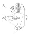
- FIG. 2 shows the computer 12 which includes a processor 40 and a memory device 42.
- the processor 40 may be embodied as any type of processor including, for example, discrete processing circuitry (for example, a collection of logic devices), general purpose integrated circuit(s), and/or application specific integrated circuit(s) (ASICs).
- the memory device 42 may be embodied as any type of memory device and may include one or more memory types, such as, random access memory (RAM) and/or read-only memory (ROM).
- the computer 12 may include other devices and circuitry typically found in a computer for performing the required functions, for example, a hard drive, input/output circuitry, and the like.
- the computer 12 is connected a display device 44 by means of a communication link 46.
- the display device 44 may form a portion of the computer 12 in some embodiments. Additionally, in some embodiments, the display device 44 or an additional display device may be positioned away from the computer 12.
- the display device 44 may be coupled with the ceiling or wall of the operating room in which the orthopaedic surgical procedure is to be performed. Additionally or alternatively, the display device 44 may be embodied as a virtual display such as a holographic display, a body mounted display such as a heads-up display, or the like.
- the computer 12 may also be coupled with a number of input devices such as a keyboard and/or a mouse for providing data input to the computer 12.
- the display device 44 is a touch-screen display device capable of receiving inputs from an orthopaedic surgeon 50. That is, the surgeon 50 can provide input data to the computer 12, such as making a selection from a number of on-screen choices, by simply touching the screen of the display device 44.
- the computer 12 is also connected to the camera unit 16 (and/or 18) by means of a communication link 48.
- the communication link 48 is a wired communication link but, in some embodiments, may be embodied as a wireless communication link.
- the camera unit 16 and the computer 12 include wireless transceivers such that the computer 12 and camera unit 16 can transmit and receive data (e.g., image data).
- data e.g., image data
- FIG. 2 it should be appreciated that the fixed camera unit 18 may alternatively be used or may be used in addition to the mobile camera unit 16.
- the CAOS system 10 may also include a number of sensors or sensor arrays 54 which may be coupled the relevant bones of a patient 56 and/or with orthopaedic surgical tools 58.
- a tibial array 60 includes a sensor array 62 and bone clamp 64.
- the illustrative bone clamp 64 is configured to be coupled with a tibia bone 66 of the patient 56 using a Schantz pin 68, but other types of bone clamps may be used.
- the sensor array 62 is coupled with the bone clamp 64 via an extension arm 70.
- the sensor array 62 includes a frame 72 and three reflective elements or sensors 74.
- the reflective elements 74 are embodied as spheres in the illustrative embodiment, but may have other geometric shapes in other embodiments.
- the reflective elements 74 are positioned in a predefined configuration that allows the computer 12 to determine the identity of the tibial array 60 based on the configuration. That is, when the tibial array 60 is positioned in a field of view 52 of the camera head 24, as shown in FIG. 2, the computer 12 is configured to determine the identity of the tibial array 60 based on the images received from the camera head 24. Additionally, based on the relative position of the reflective elements 74, the computer 12 is configured to determine the location and orientation of the tibial array 60 and, accordingly, the tibia 66 to which the array 60 is coupled.
- Sensor arrays may also be coupled to other surgical tools.
- a registration tool 80 as shown in FIG. 4, is used to register points of a bone of the patient.
- the registration tool 80 includes a sensor array 82 having three reflective elements 84 coupled with a handle 86 of the tool 80.
- the registration tool 80 also includes pointer end 88 that is used to register points of a bone.
- the reflective elements 84 are also positioned in a configuration that allows the computer 12 to determine the identity of the registration tool 80 and its relative location (the location of the pointer end 88).
- sensor arrays may be used on other surgical tools such as a tibial resection jig 90, as illustrated in FIG. 5.
- the jig 90 includes a resection guide portion 92 that is coupled with a tibia 94 at a location of the tibia 94 that is to be resected.
- the jig 90 includes a sensor array 96 that is coupled with the portion 92 via a frame 95.
- the sensor array 96 includes three reflective elements 98 that are positioned in a configuration that allows the computer 12 to determine the identity of the jig 90 and its relative location, for example, with respect to the tibia 94).
- the CAOS system 10 may be used by the orthopaedic surgeon 50 to assist in any type of orthopaedic surgical procedure including, for example, a total knee replacement procedure.
- the computer 12 and/or the display device 44 are positioned within the view of the surgeon 50.
- the computer 12 may be coupled with a movable cart 36 to facilitate such positioning.
- the camera unit 16 (and/or camera unit 18) is positioned such that the field of view 52 of the camera head 24 covers the portion of a patient 56 upon which the orthopaedic surgical procedure is to be performed, as shown in FIG. 2.
- the computer 12 of the CAOS system 10 is programmed or otherwise configured to display images of the individual surgical procedure steps which form the orthopaedic surgical procedure being performed.
- the images may be graphically rendered images or graphically enhanced photographic images.
- the images may include three dimensional rendered images of the relevant anatomical portions of a patient.
- the surgeon 50 may interact with the computer 12 to display the images of the various surgical steps in sequential order.
- the surgeon may interact with the computer 12 to view previously displayed images of surgical steps, selectively view images, instruct the computer 12 to render the anatomical result of a proposed surgical step or procedure, or perform other surgical related functions.
- the surgeon may view rendered images of the resulting bone structure of different bone resection procedures.
- the CAOS system 10 provides a surgical "walk-through" for the surgeon 50 to follow while performing the orthopaedic surgical procedure.
- the surgeon 50 may also interact with the computer 12 to control various devices of the system 10.
- the surgeon 50 may interact with the system 10 to control user preferences or settings of the display device 44.
- the computer 12 may prompt the surgeon 50 for responses.
- the computer 12 may prompt the surgeon to inquire if the surgeon has completed the current surgical step, if the surgeon would like to view other images, and the like.
- the camera unit 16 and the computer 12 also cooperate to provide the surgeon with navigational data during the orthopaedic surgical procedure. That is, the computer 12 determines and displays the location of the relevant bones and the surgical tools 58 based on the data (e.g., images) received from the camera head 24 via the communication link 48. To do so, the computer 12 compares the image data received from each of the cameras 26 and determines the location and orientation of the bones and tools 58 based on the relative location and orientation of the sensor arrays 54, 62, 82, 96. The navigational data displayed to the surgeon 50 is continually updated. In this way, the CAOS system 10 provides visual feedback of the locations of relevant bones and surgical tools for the surgeon 50 to monitor while performing the orthopaedic surgical procedure.
- the CAOS system 10 provides visual feedback of the locations of relevant bones and surgical tools for the surgeon 50 to monitor while performing the orthopaedic surgical procedure.
- a computer assisted orthopaedic surgery (CAOS) system 100 includes a controller 102 and a registration pointer 104.
- the controller 102 is connected to the registration pointer 104 by means of a communication link 106.
- the communication link 106 may be embodied as any type of communication link capable of facilitating communication between the controller 102 and the registration pointer 104.
- the communication link 106 may be a wired communication link and embodied as any number of wires, cables, or the like.
- the communication link 106 may be a wireless communication link.
- the registration pointer 104 may use any suitable wireless communication technology and protocol to communicate with the controller 102 via the communication link 106 such as, for example, a Bluetooth wireless communication protocol, a wireless local area network (WLAN) communication protocol, or the like.
- WLAN wireless local area network
- the controller 102 includes a processor 108 and a memory device 110.
- the processor 108 may be embodied as any type of processor including, for example, discrete processing circuitry (for example, a collection of logic devices), general purpose integrated circuit(s), and/or application specific integrated circuit(s) (ASICs).
- the memory device 110 may be embodied as any type of memory device and may include one or more memory types, such as, random access memory (RAM) and/or read-only memory (ROM).
- the controller 102 may include other devices and circuitry typically found in a computer for performing the required functions such as, for example, a hard drive, input/output circuitry, and the like.
- the controller 102 is connected to a display device 112 by means of a communication link 114.
- the display device 112 may form a portion of the controller 102 in some embodiments. Additionally, in some embodiments, the display device 112 or an additional display device may be positioned away from the controller 102.
- the display device 112 may be coupled to the ceiling or wall of the operating room in which the orthopaedic surgical procedure is to be performed. Additionally or alternatively, the display device 112 may be embodied as a virtual display such as a holographic display, a body mounted display such as a heads-up display, or the like.
- the controller 102 may also be coupled with a number of input devices such as a keyboard and/or a mouse for providing data input to the controller 102.
- the display device 112 is a touch-screen display device capable of receiving inputs from the orthopaedic surgeon 50 similar to the display device 44 described above with reference to FIG. 2. That is, the surgeon 50 can provide input data to the controller 102, such as making a selection from a number of on-screen choices, by simply touching the screen of the display device 112.
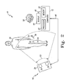
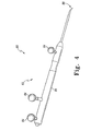
- FIG. 7 shows a registration pointer 104 which includes a handle 120 having an elongated shaft 122.
- the elongated shaft 122 has a distal end 124 that is configured to be touched or otherwise contacted to locations on a surface of a bone of a patient during a bone registration procedure as described above with reference to FIG. 4.
- the distal end 124 includes a lens 126 having a substantial hemispherical shape such that the geometric centre of the lens 126 is approximately equidistant from each point on the hemispherical surface of the lens 126.
- the lens 126 may be formed from any transparent material having a substantial hardness such that the lens 126 may be repeatedly contacted with bone and other tissue of a patient without substantially deteriorating the transparency of the material.
- the lens 126 is formed from crystal quartz.
- other optical quality, industrial grade translucent gem-like material such as quartz, ruby, diamond, and/or the like may be used.
- a camera 128 is positioned in the elongated shaft 122 toward the distal end 124.
- the camera 128 is so positioned such that a field of view 130 of the camera extends through the lens 126.
- the registration pointer 104 is usable to register bones of a patient to the controller 102 in a manner as described above with reference to FIGS. 2 and 4 and provide images of the relevant bone and other anatomical structures of the patient via the camera 128.
- the camera 128 may be embodied as any type and number of cameras capable of being located in the registration tool 104 and providing the desired image, field of view, etc.
- the camera 128 is embodied as a hemispherical camera configured to produce a number of images from which a hemispherical image may be generated.
- the camera 128 may be embodied as a panoramic camera and a wide-angle camera.
- the registration pointer 104 also includes a sensor array 132 embodied as a number of reflective elements 134.
- the reflective elements 134 are substantially similar to the reflective elements 84 illustrated in and described above with reference to FIG. 4.
- the reflective elements 134 are positioned in a predefined configuration that allows the controller 102 to determine the location and orientation of the registration pointer 104 based on images received from the camera 16.
- the registration pointer may include a magnetic or electromagnetic source such as a permanent magnet.
- the location of the registration pointer 104 may be determined based on signals received from a number of magnetic sensors as disclosed in EP-A-1803412 , EP-A-1803414 , EP-A-1803413 and EP-A-1803394 .
- the registration pointer 104 may include a magnetic or electromagnetic sensor.
- the location of the registration pointer 104 may be determined based on the signals received by the magnetic and/or electromagnetic sensors as disclosed in WO-2005/086062 and WO-2005/087125 .
- the sensor array 132 may be embodied a number of reflective elements, a number of magnetic/electromagnetic sensors, and/or a number of magnetic/electromagnetic sources such as permanent magnets. Accordingly, as used herein, the term "sensor array” is intended to refer to any number of reflective sensors, magnetic and/or electromagnetic sensors, and/or magnetic and/or electromagnetic sources.
- the registration pointer 104 may also include any number of user-selectable input devices 136.
- the registration pointer 104 may include a button 136 selectable by a user of the registration pointer 104 to capture or otherwise save an image received by the camera 128 as discussed in more detail below with reference to FIG. 10.
- the registration pointer 104 may include any number of user-selectable input devices for controlling any one or more functions of the pointer 104.
- the registration pointer 104 may include a button or other input device selectable by a user of the pointer 104 to active a light source located in the elongated shaft 122 of the pointer 104.
- the communication link 106 is embodied as a wired communication link
- the registration pointer 104 may also include a cable, wire, or other conductor 138 for connecting the pointer 104 to the controller 102.
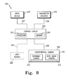
- the registration pointer 104 also includes a control circuit 200.
- the control circuit 200 is located in the handle 120 of the registration pointer 104 and is configured to control the operations of the camera 128.
- the control circuit 200 includes a processor 202 and a memory device 204.
- the processor 202 may be embodied as any type of processor including, for example, discrete processing circuitry (for example, a collection of logic devices), general purpose integrated circuit(s), and/or application specific integrated circuit(s) (ASICs).
- the memory device 202 may be embodied as any type of memory device and may include one or more memory types, such as, random access memory (RAM) and/or read-only memory (ROM).
- the control circuit 200 is electrically coupled to the camera 128 by means of a number of communication links 206 such as wires, printed circuit board traces, cables, or the like.
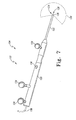
- the camera 128 is embodied as a hemispherical camera 208 and includes a panoramic camera 210 and a wide-angle camera 212. As shown in FIG. 9, the cameras 210, 212 are located in the elongated shaft 122 and toward the distal end 124 such that the field of view of each camera extends through the lens 126.
- the panoramic camera 210 has a horizontal field of view of about 360° and a vertical field of view 214 of about 120° when the elongated shaft 122 of the registration pointer 104 is located in a vertical plane 216 as shown in FIG. 9.
- the wide-angle camera 212 includes a fish-eye lens and has a field of view 218 of about 60°.
- the fields of view 214, 218 are substantially contiguous with each other in the illustrative embodiment. However, in other embodiments, cameras having fields of view of different magnitudes might be used. In such embodiments, the fields of view 214, 218 of each camera overlap each other by a predetermined amount. Such overlap is calibrated or otherwise accounted for when generating the hemispherical image based on the images received from each camera 214, 218 as discussed below with reference to FIG. 10.
- the control circuit 200 is also connected to one or more input devices 220 by means of a number of communication links 222.
- the communication links 222 may be embodied as any type of communication links, such as wires, cables, printed circuit board traces, and the like, capable of facilitating communication between the input devices 220 and the control circuit 200.
- the input devices 220 may be embodied as any type of input devices selectable by a user of the registration pointer 104.
- the input device 220 may be embodied as a button, such as the button 136 illustrated in FIG. 7, a switch, or other device selectable by the user. Any number of input devices 220 may be included and may be selected by the user to provide a request signal to the control circuit 200.
- one of the input devices 220 can be selected by a user to cause the control circuit 200 to capture or otherwise store an image received from the hemispherical camera 208.
- the image may be saved in the memory 204 of the control circuit 200 and/or the memory 110 of the controller 102.
- a transmitter circuit 224 is also included in the registration pointer 104.
- the transmitter 224 is connected to the control circuit 200 by means of a number of communication links 226.
- the communication links 226 may be similar to the communication links 222 discussed above and may be embodied as any type of communication links, such as wires, cables, printed circuit board traces, and the like, capable of facilitating communication between the transmitter circuit 224 and the control circuit 200.
- the transmitter circuit 224 may be embodied as any number of electrical devices configured to transmit any number of images received from the hemispherical camera 208 to the controller 102 via the communication link 106.
- the transmitter circuit 224 may be a wired transmitter configured to transmit the images over a wired communication link 106.
- the transmitter circuit 224 may be embodied as a wireless transmitter and may use any suitable transmission protocol, such as a Bluetooth communication protocol, a wireless local area network communication protocol, or the like, to transmit the images from the registration pointer 104 to the controller 102.
- the registration pointer 104 may also include one or more light sources 228.
- the light sources 228 are communicatively coupled to the control circuit 200 via a number of communication links 230 such as such as wires, cables, printed circuit board traces, and the like.
- the light source may be embodied as any type of light source capable of producing enough light such that the hemispherical camera 208 (comprising the cameras 210, 212 mentioned above) is capable of producing images that may be viewed by a user.
- the light source 228 is embodied a light emitting diode (LED), but other light emitting devices may be used in other embodiments.
- the light source 228 is also located in the elongated shaft 122 and toward the distal end 124 such that light emitting from the light source 228 extends through the lens 126.
- the registration pointer 104 may be used by a surgeon or other healthcare provider during an orthopaedic surgical procedure to register a bone of a patient with the controller 102.
- the surgeon may use the registration pointer 104 to view the anatomy of the patient.
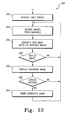
- the controller 102 may execute an algorithm 250 for displaying an image of a patient during the performance of the orthopaedic surgical procedure.
- the algorithm 250 begins with process step 252 in which a light source is activated in the region desired to be viewed by the surgeon.
- the registration pointer 104 includes the light source 228, such as a LED, the light source 228 may be activated in process step 252.
- the surgeon or other healthcare provider may select the appropriate input device 220.
- the control circuit 200 is configured to activate the light source 228 via a signal supplied on the communication link 230.
- the surgeon may activate the light source 228 or other light source by supplying the appropriate command to the controller 102 via the display 112 (in embodiments in which the display 112 is a touch screen display) or via other input device(s) such as a keyboard.
- the controller 102 is configured to transmit a signal to the registration pointer 104 via the communication link 106 to activate the light source 228.
- images are received from the hemispherical camera 208 (that is, from the panoramic camera 210 and from the wide angle camera 212) and a new image, such as a hemispherical image, is generated based on such images in process step 256.
- the images from the cameras 210, 212 may be received by the control circuit 200 and/or the controller 102. That is, in one embodiment, the control circuit 200 is configured to receive the images from the cameras 210, 212 and generate the new image (for example, a hemispherical image) based on the received images. The generated image is subsequently transmitted to the controller 102 via the transmitter circuit 224 and the communication link 106.
- control circuit 200 may be configured to transmit the images received from the cameras 210, 212 to the controller 102 and the controller 102 is configured to generate the new image based on the received images.
- the images received from the cameras 210, 212 are combined to generate a new image in the process step 256.
- the new image is a hemispherical image, but in other embodiments, other types of images may be generated.
- the images received from the cameras 210, 212 may be combined to generate the new image using any suitable algorithm.
- the images received from the cameras 210, 212 are appended to each other. In such embodiments, the new image may include an amount of overlap or duplication of visible area.
- the images received from the cameras 210, 212 are combined in such a manner that any overlap or copy of the same visible area is reduced or eliminated from the new image.
- a new image may or may not be generated based on the images received from the single camera. That is, the image received from the single camera may be displayed to the user of the system 100 as discussed below with reference to process step 260.
- the controller 102 determines if the user has requested to view the new image generated in process step 256.
- the user may request to view the generated image by selecting a button displayed on the display 112 (in embodiments in which the display is a touch screen display) or by providing a command via an input device coupled to the controller 102 such as a keyboard or mouse.
- the input devices 220 of the registration pointer 104 may include an input device 220, such as a button or switch, that the user may select to view the generated image.
- the control circuit 200 transmits a request signal via the transmitter 224 and the communication link 106 to the controller 102.
- the new image (e.g., a hemispherical image) is displayed to the user in process step 260.
- the generated image is displayed on the display device 112.
- the display 112 is embodied as a heads-up display and the generated image is displayed thereon.
- the generated image may be displayed as a stand-alone image that the surgeon may use to inspect and/or navigate the anatomy of the patient. Additionally or alternatively, the generated image may be superimposed over the rendered image of the patient's anatomy such that the rendered or calculated anatomy (e.g., a bone) of the patient is comparable to the actual anatomy as displayed in the generated image.
- the controller 102 determines if the user has requested to capture or otherwise store the generated image in process step 262.
- the user may request to save the generated image by selecting a button displayed on the display 112 or by providing a command via an input device coupled to the controller 102 such as a keyboard or mouse.
- the input devices 220 of the registration pointer 104 may include an input device, such as a button or switch, that the user may select to save the generated image.
- the control circuit 200 transmits a request signal to the controller 102 via the transmitter 224 and the communication link 106.
- the controller 102 stores the generated image in process step 264.
- the generated image may be stored in, for example, the memory device 110 or in other storage devices such as a hard drive or the like. Once stored, the generated image may be viewed by the surgeon and/or other healthcare provider at any time.
- the algorithm 250 loops back to process steps 254 in which updated images are received form the cameras 210, 212.
- the algorithm 250 may loop through process steps 254, 256, 258, and 260 to receive and display updated generated images based on the updated images received from the cameras 210, 212 such that the stream of images form a video viewable by the surgeon.
- the generated images are updated and the surgeon may thereby use the video for inspecting and/or navigating the relevant anatomy of the patient.
Landscapes
- Health & Medical Sciences (AREA)
- Engineering & Computer Science (AREA)
- Surgery (AREA)
- Life Sciences & Earth Sciences (AREA)
- Veterinary Medicine (AREA)
- Public Health (AREA)
- Nuclear Medicine, Radiotherapy & Molecular Imaging (AREA)
- Biomedical Technology (AREA)
- Heart & Thoracic Surgery (AREA)
- Medical Informatics (AREA)
- Molecular Biology (AREA)
- Animal Behavior & Ethology (AREA)
- General Health & Medical Sciences (AREA)
- Signal Processing (AREA)
- Multimedia (AREA)
- Pathology (AREA)
- Oral & Maxillofacial Surgery (AREA)
- Robotics (AREA)
- Processing Or Creating Images (AREA)
- Dental Tools And Instruments Or Auxiliary Dental Instruments (AREA)
- Prostheses (AREA)
- Endoscopes (AREA)
- Studio Devices (AREA)
- Apparatus For Radiation Diagnosis (AREA)
Applications Claiming Priority (1)
| Application Number | Priority Date | Filing Date | Title |
|---|---|---|---|
| US11/428,078 US7885701B2 (en) | 2006-06-30 | 2006-06-30 | Registration pointer and method for registering a bone of a patient to a computer assisted orthopaedic surgery system |
Publications (3)
| Publication Number | Publication Date |
|---|---|
| EP1872737A2 true EP1872737A2 (de) | 2008-01-02 |
| EP1872737A3 EP1872737A3 (de) | 2009-03-18 |
| EP1872737B1 EP1872737B1 (de) | 2011-10-26 |
Family
ID=38608852
Family Applications (1)
| Application Number | Title | Priority Date | Filing Date |
|---|---|---|---|
| EP07252633A Active EP1872737B1 (de) | 2006-06-30 | 2007-06-28 | Computergestütztes orthopädisch-chirurgisches System |
Country Status (3)
| Country | Link |
|---|---|
| US (2) | US7885701B2 (de) |
| EP (1) | EP1872737B1 (de) |
| AT (1) | ATE530138T1 (de) |
Cited By (6)
| Publication number | Priority date | Publication date | Assignee | Title |
|---|---|---|---|---|
| WO2012152879A1 (de) * | 2011-05-11 | 2012-11-15 | Scopis Gmbh | Registriervorrichtung, verfahren und vorrichtung zum registrieren einer oberfläche eines objektes |
| WO2016005718A1 (en) * | 2014-07-07 | 2016-01-14 | Kenneth Francis Prendergast | Apparatus for clinical use |
| WO2018067794A1 (en) * | 2016-10-05 | 2018-04-12 | Nuvasive, Inc. | Surgical navigation system and related methods |
| ES2919785A1 (es) * | 2021-01-26 | 2022-07-28 | Coretti Stephan Meschian | Sistema de cirugía navegada con registro mediante instrumental paciente específico con conexión multidireccional |
| US11439469B2 (en) | 2018-06-19 | 2022-09-13 | Howmedica Osteonics Corp. | Virtual guidance for orthopedic surgical procedures |
| US11612440B2 (en) | 2019-09-05 | 2023-03-28 | Nuvasive, Inc. | Surgical instrument tracking devices and related methods |
Families Citing this family (36)
| Publication number | Priority date | Publication date | Assignee | Title |
|---|---|---|---|---|
| WO2003034705A2 (en) * | 2001-10-19 | 2003-04-24 | University Of North Carolina At Chapel Hill | Methods and systems for dynamic virtual convergence and head mountable display |
| US8560047B2 (en) | 2006-06-16 | 2013-10-15 | Board Of Regents Of The University Of Nebraska | Method and apparatus for computer aided surgery |
| US7728868B2 (en) * | 2006-08-02 | 2010-06-01 | Inneroptic Technology, Inc. | System and method of providing real-time dynamic imagery of a medical procedure site using multiple modalities |
| WO2009094646A2 (en) * | 2008-01-24 | 2009-07-30 | The University Of North Carolina At Chapel Hill | Methods, systems, and computer readable media for image guided ablation |
| US8340379B2 (en) | 2008-03-07 | 2012-12-25 | Inneroptic Technology, Inc. | Systems and methods for displaying guidance data based on updated deformable imaging data |
| US8554307B2 (en) | 2010-04-12 | 2013-10-08 | Inneroptic Technology, Inc. | Image annotation in image-guided medical procedures |
| US8690776B2 (en) | 2009-02-17 | 2014-04-08 | Inneroptic Technology, Inc. | Systems, methods, apparatuses, and computer-readable media for image guided surgery |
| US11464578B2 (en) | 2009-02-17 | 2022-10-11 | Inneroptic Technology, Inc. | Systems, methods, apparatuses, and computer-readable media for image management in image-guided medical procedures |
| US8641621B2 (en) * | 2009-02-17 | 2014-02-04 | Inneroptic Technology, Inc. | Systems, methods, apparatuses, and computer-readable media for image management in image-guided medical procedures |
| US20110043612A1 (en) * | 2009-07-31 | 2011-02-24 | Inneroptic Technology Inc. | Dual-tube stereoscope |
| US20110082351A1 (en) * | 2009-10-07 | 2011-04-07 | Inneroptic Technology, Inc. | Representing measurement information during a medical procedure |
| US9282947B2 (en) | 2009-12-01 | 2016-03-15 | Inneroptic Technology, Inc. | Imager focusing based on intraoperative data |
| EP2720631B1 (de) | 2011-06-16 | 2022-01-26 | Smith&Nephew, Inc. | Chirurgische ausrichtung mittels referenzen |
| CN106913366B (zh) | 2011-06-27 | 2021-02-26 | 内布拉斯加大学评议会 | 工具承载的追踪系统和计算机辅助外科方法 |
| US9498231B2 (en) | 2011-06-27 | 2016-11-22 | Board Of Regents Of The University Of Nebraska | On-board tool tracking system and methods of computer assisted surgery |
| US11911117B2 (en) | 2011-06-27 | 2024-02-27 | Board Of Regents Of The University Of Nebraska | On-board tool tracking system and methods of computer assisted surgery |
| US8670816B2 (en) | 2012-01-30 | 2014-03-11 | Inneroptic Technology, Inc. | Multiple medical device guidance |
| US10314559B2 (en) | 2013-03-14 | 2019-06-11 | Inneroptic Technology, Inc. | Medical device guidance |
| US10105149B2 (en) | 2013-03-15 | 2018-10-23 | Board Of Regents Of The University Of Nebraska | On-board tool tracking system and methods of computer assisted surgery |
| US9566020B2 (en) | 2013-03-18 | 2017-02-14 | Orthosensor Inc | System and method for assessing, measuring, and correcting an anterior-posterior bone cut |
| US11793424B2 (en) | 2013-03-18 | 2023-10-24 | Orthosensor, Inc. | Kinetic assessment and alignment of the muscular-skeletal system and method therefor |
| US9858798B2 (en) | 2013-05-28 | 2018-01-02 | Aai Corporation | Cloud based command and control system integrating services across multiple platforms |
| DE102013211342A1 (de) * | 2013-06-18 | 2014-12-18 | Siemens Aktiengesellschaft | Fotobasiertes 3D-Oberflächen-Inspektionssystem |
| US9901406B2 (en) | 2014-10-02 | 2018-02-27 | Inneroptic Technology, Inc. | Affected region display associated with a medical device |
| US10188467B2 (en) | 2014-12-12 | 2019-01-29 | Inneroptic Technology, Inc. | Surgical guidance intersection display |
| CN104887327B (zh) * | 2015-06-24 | 2017-03-29 | 深圳安科高技术股份有限公司 | 一种用于手术导航的触敏式配准工具及其配准方法 |
| US9949700B2 (en) | 2015-07-22 | 2018-04-24 | Inneroptic Technology, Inc. | Medical device approaches |
| US10085645B2 (en) | 2015-09-30 | 2018-10-02 | DePuy Synthes Products, Inc. | Implant placement method with feedback |
| US9675319B1 (en) | 2016-02-17 | 2017-06-13 | Inneroptic Technology, Inc. | Loupe display |
| US10278778B2 (en) | 2016-10-27 | 2019-05-07 | Inneroptic Technology, Inc. | Medical device navigation using a virtual 3D space |
| EP3609424A1 (de) | 2017-04-14 | 2020-02-19 | Stryker Corporation | Chirurgische systeme und verfahren zur ermöglichung der interoperativen ad-hoc-planung von chirurgischen eingriffen |
| US11259879B2 (en) | 2017-08-01 | 2022-03-01 | Inneroptic Technology, Inc. | Selective transparency to assist medical device navigation |
| US10695109B2 (en) | 2017-12-13 | 2020-06-30 | DePuy Synthes Products, Inc. | Intramedullary nail with cannulation access hole |
| CA3088311A1 (en) | 2018-01-12 | 2019-07-18 | Peter L. BONO | Surgical sensor anchor system |
| US11484365B2 (en) | 2018-01-23 | 2022-11-01 | Inneroptic Technology, Inc. | Medical image guidance |
| JP2023177422A (ja) * | 2022-06-02 | 2023-12-14 | キヤノン株式会社 | 画像処理装置、画像処理方法及びプログラム |
Citations (1)
| Publication number | Priority date | Publication date | Assignee | Title |
|---|---|---|---|---|
| WO2005000139A1 (en) | 2003-04-28 | 2005-01-06 | Bracco Imaging Spa | Surgical navigation imaging system |
Family Cites Families (11)
| Publication number | Priority date | Publication date | Assignee | Title |
|---|---|---|---|---|
| US5023725A (en) * | 1989-10-23 | 1991-06-11 | Mccutchen David | Method and apparatus for dodecahedral imaging system |
| US5990941A (en) | 1991-05-13 | 1999-11-23 | Interactive Pictures Corporation | Method and apparatus for the interactive display of any portion of a spherical image |
| US5230623A (en) * | 1991-12-10 | 1993-07-27 | Radionics, Inc. | Operating pointer with interactive computergraphics |
| US6331869B1 (en) * | 1998-08-07 | 2001-12-18 | Be Here Corporation | Method and apparatus for electronically distributing motion panoramic images |
| US6611282B1 (en) * | 1999-01-04 | 2003-08-26 | Remote Reality | Super wide-angle panoramic imaging apparatus |
| US8229549B2 (en) * | 2004-07-09 | 2012-07-24 | Tyco Healthcare Group Lp | Surgical imaging device |
| US7336299B2 (en) | 2003-07-03 | 2008-02-26 | Physical Optics Corporation | Panoramic video system with real-time distortion-free imaging |
| US7840253B2 (en) * | 2003-10-17 | 2010-11-23 | Medtronic Navigation, Inc. | Method and apparatus for surgical navigation |
| US7317955B2 (en) * | 2003-12-12 | 2008-01-08 | Conmed Corporation | Virtual operating room integration |
| US7922654B2 (en) * | 2004-08-09 | 2011-04-12 | Boston Scientific Scimed, Inc. | Fiber optic imaging catheter |
| WO2007011306A2 (en) | 2005-07-20 | 2007-01-25 | Bracco Imaging S.P.A. | A method of and apparatus for mapping a virtual model of an object to the object |
-
2006
- 2006-06-30 US US11/428,078 patent/US7885701B2/en active Active
-
2007
- 2007-06-28 AT AT07252633T patent/ATE530138T1/de not_active IP Right Cessation
- 2007-06-28 EP EP07252633A patent/EP1872737B1/de active Active
-
2011
- 2011-01-03 US US12/983,676 patent/US8521255B2/en active Active
Patent Citations (1)
| Publication number | Priority date | Publication date | Assignee | Title |
|---|---|---|---|---|
| WO2005000139A1 (en) | 2003-04-28 | 2005-01-06 | Bracco Imaging Spa | Surgical navigation imaging system |
Cited By (17)
| Publication number | Priority date | Publication date | Assignee | Title |
|---|---|---|---|---|
| WO2012152879A1 (de) * | 2011-05-11 | 2012-11-15 | Scopis Gmbh | Registriervorrichtung, verfahren und vorrichtung zum registrieren einer oberfläche eines objektes |
| WO2016005718A1 (en) * | 2014-07-07 | 2016-01-14 | Kenneth Francis Prendergast | Apparatus for clinical use |
| WO2018067794A1 (en) * | 2016-10-05 | 2018-04-12 | Nuvasive, Inc. | Surgical navigation system and related methods |
| EP3375399A3 (de) * | 2016-10-05 | 2018-12-26 | NuVasive, Inc. | Chirurgisches navigationssystem und zugehörige verfahren |
| JP2020511171A (ja) * | 2016-10-05 | 2020-04-16 | ニューヴェイジヴ,インコーポレイテッド | 外科ナビゲーションシステム及び関連する方法 |
| US11350995B2 (en) | 2016-10-05 | 2022-06-07 | Nuvasive, Inc. | Surgical navigation systems and methods |
| AU2017340607B2 (en) * | 2016-10-05 | 2022-10-27 | Nuvasive, Inc. | Surgical navigation system and related methods |
| US11478310B2 (en) | 2018-06-19 | 2022-10-25 | Howmedica Osteonics Corp. | Virtual guidance for ankle surgery procedures |
| US11439469B2 (en) | 2018-06-19 | 2022-09-13 | Howmedica Osteonics Corp. | Virtual guidance for orthopedic surgical procedures |
| US11571263B2 (en) | 2018-06-19 | 2023-02-07 | Howmedica Osteonics Corp. | Mixed-reality surgical system with physical markers for registration of virtual models |
| US11645531B2 (en) | 2018-06-19 | 2023-05-09 | Howmedica Osteonics Corp. | Mixed-reality surgical system with physical markers for registration of virtual models |
| US11657287B2 (en) | 2018-06-19 | 2023-05-23 | Howmedica Osteonics Corp. | Virtual guidance for ankle surgery procedures |
| US12020801B2 (en) | 2018-06-19 | 2024-06-25 | Howmedica Osteonics Corp. | Virtual guidance for orthopedic surgical procedures |
| US12046349B2 (en) | 2018-06-19 | 2024-07-23 | Howmedica Osteonics Corp. | Visualization of intraoperatively modified surgical plans |
| US12050999B2 (en) | 2018-06-19 | 2024-07-30 | Howmedica Osteonics Corp. | Virtual guidance for orthopedic surgical procedures |
| US11612440B2 (en) | 2019-09-05 | 2023-03-28 | Nuvasive, Inc. | Surgical instrument tracking devices and related methods |
| ES2919785A1 (es) * | 2021-01-26 | 2022-07-28 | Coretti Stephan Meschian | Sistema de cirugía navegada con registro mediante instrumental paciente específico con conexión multidireccional |
Also Published As
| Publication number | Publication date |
|---|---|
| US20080004516A1 (en) | 2008-01-03 |
| US8521255B2 (en) | 2013-08-27 |
| ATE530138T1 (de) | 2011-11-15 |
| EP1872737B1 (de) | 2011-10-26 |
| US7885701B2 (en) | 2011-02-08 |
| EP1872737A3 (de) | 2009-03-18 |
| US20110098577A1 (en) | 2011-04-28 |
Similar Documents
| Publication | Publication Date | Title |
|---|---|---|
| EP1872737B1 (de) | Computergestütztes orthopädisch-chirurgisches System | |
| CN113259584B (zh) | 摄像机跟踪系统 | |
| EP1800616B1 (de) | Computerunterstütztes Chirurgiesystem mit Lichtquelle | |
| US11510750B2 (en) | Leveraging two-dimensional digital imaging and communication in medicine imagery in three-dimensional extended reality applications | |
| US20210169581A1 (en) | Extended reality instrument interaction zone for navigated robotic surgery | |
| JP5055352B2 (ja) | 患者の体との関係で手術器具を三次元トラッキングするためのシステム | |
| EP1884215A1 (de) | Vorrichtung zum Einziehen von Patientengewebe | |
| TW572749B (en) | A guide system | |
| CN112932661A (zh) | 外科手术系统 | |
| EP1839707A1 (de) | System zur Überwachung der kinematischen Bewegung eines Patienten | |
| JP2004530485A (ja) | ガイドシステムおよびそのためのプローブ | |
| EP2584989B1 (de) | Erzeugung von bildern für mindestens zwei anzeigen bei der bildgeführten chirurgie | |
| CN110650704A (zh) | 用于检测图像捕获装置的视野内的物体的系统和方法 | |
| JP2021129984A (ja) | 予定の器具アタッチメントの仮想モデルの表示により物理的器具アタッチメントの正しい選択を確実にする | |
| JP2001204738A (ja) | 手術用ナビゲーションシステム | |
| US20050279368A1 (en) | Computer assisted surgery input/output systems and processes | |
| CN113558762A (zh) | 将手术工具与由扩展现实头戴装置的摄像机跟踪的参考阵列配准以用于手术期间的辅助导航 | |
| JP7282816B2 (ja) | ナビゲートされたロボット外科手術のためのエクステンデッドリアリティ器具相互作用ゾーン | |
| CN114727848A (zh) | 用于ent规程的可视化系统和方法 | |
| JP2023530652A (ja) | コンピュータ支援インターベンション用の空間認識ディスプレイ | |
| US20230076894A1 (en) | Surgical navigation system on wearable computer combining augmented reality and robotics | |
| US20240206988A1 (en) | Graphical user interface for a surgical navigation system |
Legal Events
| Date | Code | Title | Description |
|---|---|---|---|
| PUAI | Public reference made under article 153(3) epc to a published international application that has entered the european phase |
Free format text: ORIGINAL CODE: 0009012 |
|
| AK | Designated contracting states |
Kind code of ref document: A2 Designated state(s): AT BE BG CH CY CZ DE DK EE ES FI FR GB GR HU IE IS IT LI LT LU LV MC MT NL PL PT RO SE SI SK TR |
|
| AX | Request for extension of the european patent |
Extension state: AL BA HR MK YU |
|
| PUAL | Search report despatched |
Free format text: ORIGINAL CODE: 0009013 |
|
| AK | Designated contracting states |
Kind code of ref document: A3 Designated state(s): AT BE BG CH CY CZ DE DK EE ES FI FR GB GR HU IE IS IT LI LT LU LV MC MT NL PL PT RO SE SI SK TR |
|
| AX | Request for extension of the european patent |
Extension state: AL BA HR MK RS |
|
| RIC1 | Information provided on ipc code assigned before grant |
Ipc: H04N 5/262 20060101ALI20090212BHEP Ipc: A61B 19/00 20060101AFI20071029BHEP |
|
| 17P | Request for examination filed |
Effective date: 20090401 |
|
| 17Q | First examination report despatched |
Effective date: 20090516 |
|
| R17C | First examination report despatched (corrected) |
Effective date: 20090515 |
|
| AKX | Designation fees paid |
Designated state(s): AT BE BG CH CY CZ DE DK EE ES FI FR GB GR HU IE IS IT LI LT LU LV MC MT NL PL PT RO SE SI SK TR |
|
| GRAP | Despatch of communication of intention to grant a patent |
Free format text: ORIGINAL CODE: EPIDOSNIGR1 |
|
| GRAS | Grant fee paid |
Free format text: ORIGINAL CODE: EPIDOSNIGR3 |
|
| GRAA | (expected) grant |
Free format text: ORIGINAL CODE: 0009210 |
|
| AK | Designated contracting states |
Kind code of ref document: B1 Designated state(s): AT BE BG CH CY CZ DE DK EE ES FI FR GB GR HU IE IS IT LI LT LU LV MC MT NL PL PT RO SE SI SK TR |
|
| REG | Reference to a national code |
Ref country code: GB Ref legal event code: FG4D |
|
| REG | Reference to a national code |
Ref country code: CH Ref legal event code: NV Representative=s name: E. BLUM & CO. AG PATENT- UND MARKENANWAELTE VSP Ref country code: CH Ref legal event code: EP |
|
| REG | Reference to a national code |
Ref country code: IE Ref legal event code: FG4D |
|
| REG | Reference to a national code |
Ref country code: DE Ref legal event code: R096 Ref document number: 602007018169 Country of ref document: DE Effective date: 20120126 |
|
| REG | Reference to a national code |
Ref country code: NL Ref legal event code: VDEP Effective date: 20111026 |
|
| LTIE | Lt: invalidation of european patent or patent extension |
Effective date: 20111026 |
|
| REG | Reference to a national code |
Ref country code: AT Ref legal event code: MK05 Ref document number: 530138 Country of ref document: AT Kind code of ref document: T Effective date: 20111026 |
|
| PG25 | Lapsed in a contracting state [announced via postgrant information from national office to epo] |
Ref country code: LT Free format text: LAPSE BECAUSE OF FAILURE TO SUBMIT A TRANSLATION OF THE DESCRIPTION OR TO PAY THE FEE WITHIN THE PRESCRIBED TIME-LIMIT Effective date: 20111026 Ref country code: IS Free format text: LAPSE BECAUSE OF FAILURE TO SUBMIT A TRANSLATION OF THE DESCRIPTION OR TO PAY THE FEE WITHIN THE PRESCRIBED TIME-LIMIT Effective date: 20120226 Ref country code: BE Free format text: LAPSE BECAUSE OF FAILURE TO SUBMIT A TRANSLATION OF THE DESCRIPTION OR TO PAY THE FEE WITHIN THE PRESCRIBED TIME-LIMIT Effective date: 20111026 |
|
| PG25 | Lapsed in a contracting state [announced via postgrant information from national office to epo] |
Ref country code: NL Free format text: LAPSE BECAUSE OF FAILURE TO SUBMIT A TRANSLATION OF THE DESCRIPTION OR TO PAY THE FEE WITHIN THE PRESCRIBED TIME-LIMIT Effective date: 20111026 Ref country code: PT Free format text: LAPSE BECAUSE OF FAILURE TO SUBMIT A TRANSLATION OF THE DESCRIPTION OR TO PAY THE FEE WITHIN THE PRESCRIBED TIME-LIMIT Effective date: 20120227 Ref country code: GR Free format text: LAPSE BECAUSE OF FAILURE TO SUBMIT A TRANSLATION OF THE DESCRIPTION OR TO PAY THE FEE WITHIN THE PRESCRIBED TIME-LIMIT Effective date: 20120127 Ref country code: LV Free format text: LAPSE BECAUSE OF FAILURE TO SUBMIT A TRANSLATION OF THE DESCRIPTION OR TO PAY THE FEE WITHIN THE PRESCRIBED TIME-LIMIT Effective date: 20111026 Ref country code: SI Free format text: LAPSE BECAUSE OF FAILURE TO SUBMIT A TRANSLATION OF THE DESCRIPTION OR TO PAY THE FEE WITHIN THE PRESCRIBED TIME-LIMIT Effective date: 20111026 Ref country code: SE Free format text: LAPSE BECAUSE OF FAILURE TO SUBMIT A TRANSLATION OF THE DESCRIPTION OR TO PAY THE FEE WITHIN THE PRESCRIBED TIME-LIMIT Effective date: 20111026 Ref country code: PL Free format text: LAPSE BECAUSE OF FAILURE TO SUBMIT A TRANSLATION OF THE DESCRIPTION OR TO PAY THE FEE WITHIN THE PRESCRIBED TIME-LIMIT Effective date: 20111026 |
|
| PG25 | Lapsed in a contracting state [announced via postgrant information from national office to epo] |
Ref country code: CY Free format text: LAPSE BECAUSE OF FAILURE TO SUBMIT A TRANSLATION OF THE DESCRIPTION OR TO PAY THE FEE WITHIN THE PRESCRIBED TIME-LIMIT Effective date: 20111026 |
|
| PG25 | Lapsed in a contracting state [announced via postgrant information from national office to epo] |
Ref country code: CZ Free format text: LAPSE BECAUSE OF FAILURE TO SUBMIT A TRANSLATION OF THE DESCRIPTION OR TO PAY THE FEE WITHIN THE PRESCRIBED TIME-LIMIT Effective date: 20111026 Ref country code: SK Free format text: LAPSE BECAUSE OF FAILURE TO SUBMIT A TRANSLATION OF THE DESCRIPTION OR TO PAY THE FEE WITHIN THE PRESCRIBED TIME-LIMIT Effective date: 20111026 Ref country code: DK Free format text: LAPSE BECAUSE OF FAILURE TO SUBMIT A TRANSLATION OF THE DESCRIPTION OR TO PAY THE FEE WITHIN THE PRESCRIBED TIME-LIMIT Effective date: 20111026 Ref country code: BG Free format text: LAPSE BECAUSE OF FAILURE TO SUBMIT A TRANSLATION OF THE DESCRIPTION OR TO PAY THE FEE WITHIN THE PRESCRIBED TIME-LIMIT Effective date: 20120126 Ref country code: EE Free format text: LAPSE BECAUSE OF FAILURE TO SUBMIT A TRANSLATION OF THE DESCRIPTION OR TO PAY THE FEE WITHIN THE PRESCRIBED TIME-LIMIT Effective date: 20111026 |
|
| PG25 | Lapsed in a contracting state [announced via postgrant information from national office to epo] |
Ref country code: IT Free format text: LAPSE BECAUSE OF FAILURE TO SUBMIT A TRANSLATION OF THE DESCRIPTION OR TO PAY THE FEE WITHIN THE PRESCRIBED TIME-LIMIT Effective date: 20111026 Ref country code: RO Free format text: LAPSE BECAUSE OF FAILURE TO SUBMIT A TRANSLATION OF THE DESCRIPTION OR TO PAY THE FEE WITHIN THE PRESCRIBED TIME-LIMIT Effective date: 20111026 |
|
| PLBE | No opposition filed within time limit |
Free format text: ORIGINAL CODE: 0009261 |
|
| STAA | Information on the status of an ep patent application or granted ep patent |
Free format text: STATUS: NO OPPOSITION FILED WITHIN TIME LIMIT |
|
| 26N | No opposition filed |
Effective date: 20120727 |
|
| REG | Reference to a national code |
Ref country code: DE Ref legal event code: R097 Ref document number: 602007018169 Country of ref document: DE Effective date: 20120727 |
|
| PG25 | Lapsed in a contracting state [announced via postgrant information from national office to epo] |
Ref country code: AT Free format text: LAPSE BECAUSE OF FAILURE TO SUBMIT A TRANSLATION OF THE DESCRIPTION OR TO PAY THE FEE WITHIN THE PRESCRIBED TIME-LIMIT Effective date: 20111026 Ref country code: MC Free format text: LAPSE BECAUSE OF NON-PAYMENT OF DUE FEES Effective date: 20120630 |
|
| PG25 | Lapsed in a contracting state [announced via postgrant information from national office to epo] |
Ref country code: ES Free format text: LAPSE BECAUSE OF FAILURE TO SUBMIT A TRANSLATION OF THE DESCRIPTION OR TO PAY THE FEE WITHIN THE PRESCRIBED TIME-LIMIT Effective date: 20120206 |
|
| PG25 | Lapsed in a contracting state [announced via postgrant information from national office to epo] |
Ref country code: FI Free format text: LAPSE BECAUSE OF FAILURE TO SUBMIT A TRANSLATION OF THE DESCRIPTION OR TO PAY THE FEE WITHIN THE PRESCRIBED TIME-LIMIT Effective date: 20111026 |
|
| PG25 | Lapsed in a contracting state [announced via postgrant information from national office to epo] |
Ref country code: MT Free format text: LAPSE BECAUSE OF FAILURE TO SUBMIT A TRANSLATION OF THE DESCRIPTION OR TO PAY THE FEE WITHIN THE PRESCRIBED TIME-LIMIT Effective date: 20111026 |
|
| PG25 | Lapsed in a contracting state [announced via postgrant information from national office to epo] |
Ref country code: TR Free format text: LAPSE BECAUSE OF FAILURE TO SUBMIT A TRANSLATION OF THE DESCRIPTION OR TO PAY THE FEE WITHIN THE PRESCRIBED TIME-LIMIT Effective date: 20111026 |
|
| PG25 | Lapsed in a contracting state [announced via postgrant information from national office to epo] |
Ref country code: LU Free format text: LAPSE BECAUSE OF NON-PAYMENT OF DUE FEES Effective date: 20120628 |
|
| PG25 | Lapsed in a contracting state [announced via postgrant information from national office to epo] |
Ref country code: HU Free format text: LAPSE BECAUSE OF FAILURE TO SUBMIT A TRANSLATION OF THE DESCRIPTION OR TO PAY THE FEE WITHIN THE PRESCRIBED TIME-LIMIT Effective date: 20070628 |
|
| REG | Reference to a national code |
Ref country code: FR Ref legal event code: PLFP Year of fee payment: 10 |
|
| REG | Reference to a national code |
Ref country code: FR Ref legal event code: PLFP Year of fee payment: 11 |
|
| REG | Reference to a national code |
Ref country code: FR Ref legal event code: PLFP Year of fee payment: 12 |
|
| PGFP | Annual fee paid to national office [announced via postgrant information from national office to epo] |
Ref country code: CH Payment date: 20230702 Year of fee payment: 17 |
|
| PGFP | Annual fee paid to national office [announced via postgrant information from national office to epo] |
Ref country code: IE Payment date: 20240509 Year of fee payment: 18 |
|
| PGFP | Annual fee paid to national office [announced via postgrant information from national office to epo] |
Ref country code: GB Payment date: 20240509 Year of fee payment: 18 |
|
| PGFP | Annual fee paid to national office [announced via postgrant information from national office to epo] |
Ref country code: DE Payment date: 20240502 Year of fee payment: 18 |
|
| PGFP | Annual fee paid to national office [announced via postgrant information from national office to epo] |
Ref country code: FR Payment date: 20240509 Year of fee payment: 18 |