EP1871096A2 - Positioning device, shake correcting device and electronics - Google Patents
Positioning device, shake correcting device and electronics Download PDFInfo
- Publication number
- EP1871096A2 EP1871096A2 EP07012159A EP07012159A EP1871096A2 EP 1871096 A2 EP1871096 A2 EP 1871096A2 EP 07012159 A EP07012159 A EP 07012159A EP 07012159 A EP07012159 A EP 07012159A EP 1871096 A2 EP1871096 A2 EP 1871096A2
- Authority
- EP
- European Patent Office
- Prior art keywords
- magnet
- set forth
- positioning device
- drive
- shake correcting
- Prior art date
- Legal status (The legal status is an assumption and is not a legal conclusion. Google has not performed a legal analysis and makes no representation as to the accuracy of the status listed.)
- Granted
Links
Images




Classifications
-
- G—PHYSICS
- G03—PHOTOGRAPHY; CINEMATOGRAPHY; ANALOGOUS TECHNIQUES USING WAVES OTHER THAN OPTICAL WAVES; ELECTROGRAPHY; HOLOGRAPHY
- G03B—APPARATUS OR ARRANGEMENTS FOR TAKING PHOTOGRAPHS OR FOR PROJECTING OR VIEWING THEM; APPARATUS OR ARRANGEMENTS EMPLOYING ANALOGOUS TECHNIQUES USING WAVES OTHER THAN OPTICAL WAVES; ACCESSORIES THEREFOR
- G03B5/00—Adjustment of optical system relative to image or object surface other than for focusing
- G03B5/06—Swinging lens about normal to the optical axis
-
- G—PHYSICS
- G02—OPTICS
- G02B—OPTICAL ELEMENTS, SYSTEMS OR APPARATUS
- G02B27/00—Optical systems or apparatus not provided for by any of the groups G02B1/00 - G02B26/00, G02B30/00
- G02B27/64—Imaging systems using optical elements for stabilisation of the lateral and angular position of the image
- G02B27/646—Imaging systems using optical elements for stabilisation of the lateral and angular position of the image compensating for small deviations, e.g. due to vibration or shake
-
- G—PHYSICS
- G03—PHOTOGRAPHY; CINEMATOGRAPHY; ANALOGOUS TECHNIQUES USING WAVES OTHER THAN OPTICAL WAVES; ELECTROGRAPHY; HOLOGRAPHY
- G03B—APPARATUS OR ARRANGEMENTS FOR TAKING PHOTOGRAPHS OR FOR PROJECTING OR VIEWING THEM; APPARATUS OR ARRANGEMENTS EMPLOYING ANALOGOUS TECHNIQUES USING WAVES OTHER THAN OPTICAL WAVES; ACCESSORIES THEREFOR
- G03B17/00—Details of cameras or camera bodies; Accessories therefor
- G03B17/02—Bodies
- G03B17/17—Bodies with reflectors arranged in beam forming the photographic image, e.g. for reducing dimensions of camera
-
- G—PHYSICS
- G03—PHOTOGRAPHY; CINEMATOGRAPHY; ANALOGOUS TECHNIQUES USING WAVES OTHER THAN OPTICAL WAVES; ELECTROGRAPHY; HOLOGRAPHY
- G03B—APPARATUS OR ARRANGEMENTS FOR TAKING PHOTOGRAPHS OR FOR PROJECTING OR VIEWING THEM; APPARATUS OR ARRANGEMENTS EMPLOYING ANALOGOUS TECHNIQUES USING WAVES OTHER THAN OPTICAL WAVES; ACCESSORIES THEREFOR
- G03B2205/00—Adjustment of optical system relative to image or object surface other than for focusing
- G03B2205/0007—Movement of one or more optical elements for control of motion blur
-
- G—PHYSICS
- G03—PHOTOGRAPHY; CINEMATOGRAPHY; ANALOGOUS TECHNIQUES USING WAVES OTHER THAN OPTICAL WAVES; ELECTROGRAPHY; HOLOGRAPHY
- G03B—APPARATUS OR ARRANGEMENTS FOR TAKING PHOTOGRAPHS OR FOR PROJECTING OR VIEWING THEM; APPARATUS OR ARRANGEMENTS EMPLOYING ANALOGOUS TECHNIQUES USING WAVES OTHER THAN OPTICAL WAVES; ACCESSORIES THEREFOR
- G03B2205/00—Adjustment of optical system relative to image or object surface other than for focusing
- G03B2205/0053—Driving means for the movement of one or more optical element
- G03B2205/0069—Driving means for the movement of one or more optical element using electromagnetic actuators, e.g. voice coils
Definitions
- the present invention relates to a positioning device, a shake correcting device, electronics and a production method of the positioning device.
- a positioning device using a drive unit and a position detecting device is, for example, known as those installed in a camera, etc. (refer to the Japanese Unexamined Patent Publication No. 2002-196382 ).
- a positioning device of the related art as above has had a disadvantage that positioning becomes difficult due to a rotation moment generated between a magnet provided to the drive unit and a magnet provided to the position detecting device.
- An object of the present invention is to provide a positioning device having an improved positioning accuracy, a shake correcting device, electronics, and a production method of the positioning device.
- a positioning device of the present invention comprises a first member, a second member, a drive member, a first detection part and a second detection part.
- a first member is provided with a first magnet arranged along a first axis and a second magnet arranged along a second axis intersecting with the first axis, and a second member is provided to face to the first member.
- a drive member includes a first element provided to the first member and a second element provided to the second member and relatively drives the first member and the second member by an electromagnetic action between the first element and the second element.
- a first detection portion detects a relative move of the first member and the second member with respect to the first axis direction in cooperation with the first magnet
- a second detection portion detects a relative move of the first member and the second member with respect to the second axis direction in cooperation with the second magnet.
- the first magnet is arranged so as to reduce a rotation moment generated by an electromagnetic connection between the second magnet and the second element. According to the positioning device of the present invention, a rotation moment generated between the second magnet and the second element is reduced so that the positioning accuracy is improved.
- a production method of a positioning device of the present invention comprises the step of forming a mark that identifies magnetic poles on at least one of the first magnet and the second magnet and the step of attaching the magnet having the mark to the first member.
- a production method of a positioning device according to another aspect of the present invention comprises the step of forming a mark that identifies magnetic poles on a drive magnet and the step of attaching the drive magnet having the mark to the first member or the second member. According to a production method of a positioning device of the present invention, magnetic poles of magnets can be easily identified, so that attaching with erroneous magnetic poles can be prevented.
- FIG 1 is a perspective view showing a digital camera according to first and second embodiments.
- FIG. 2A and FIG. 2B are views showing a shake correcting device installed in the digital camera shown in FIG. 1, wherein FIG 2A is a plan view of the shake correcting device and FIG. 2B is a sectional view along IIB-IIB in FIG. 2A.
- a digital camera 100 (hereinafter, referred to as a camera 100) is a camera with an unchangeable lens and comprises a body 110 and a lens barrel 120.
- the body 110 is a box-shaped container having a space inside and is formed to be an approximately rectangular parallelepiped shape, for example, made by a synthetic resin and a metal material, such as an aluminum alloy
- the lens tube 120 is held in the space inside the body 110 and comprises a first lens group 1, a prism 2, a CCD (Charge Coupled Device) 3 and a shake correcting device 10.
- a switch SW is a switch used, for example, for a shutter release operation and control of the shake correcting device, etc.
- the switch SW is provided on the opposite side of the first lens group 1 in the body 110.
- a switch VRSW is a switch used for operating of activating or deactivating the shake correcting device.
- the switch VRSW is provided on the opposite side of the first lens group 1 in the body 110.
- the first lens group 1 is provided to the closest side to a subject of shooting in an image pickup optical system held in the lens tube 120.
- the first lens group 1 is arranged on a plane facing to a subject among planes of the body 110 in a state that the incident surface is exposed.
- the prism 2 is arranged on the emitting side of the first lens group 1 inside the body 110 and is a right angle prism for totally reflecting a light emitted from the first lens group 1 to bend the direction, for example, by 90°.
- an image pickup optical system of the camera 100 will be explained by giving reference numbers A1 and A2 to a light axis on the incident side and a light axis on the emitting side of the prism 2, respectively.
- the CCD 3 is a photoelectric conversion element for converting a subject image light obtained by the image pickup optical system of the camera 100 including the first lens group 1 to an electric signal.
- the CCD 3 is arranged on the emitting side of the prism 2 and vertically below the prism 2 in a normal shooting position of the camera 100.
- CMOS Complementary Metal Oxide Semiconductor
- the normal shooting position of the camera 100 indicates a posture of the camera 100 when shooting a landscape-oriented image by setting the optical axis A1 approximately horizontal.
- An image pickup surface of the CCD 3 becomes approximately horizontal in a state that the camera 100 is at the normal shooting position.
- the lens tube 120 is provided with a plurality of lens groups including a zoom lens and a focus lens between the first lens group 1 and the prism 2 and between the prism 2 and the CCD 3.
- the shake correcting device 10 is arranged on the light axis A2 between the prism 2 and the CCD 3.
- the shake correcting device 10 comprises, as shown in FIG. 2A and FIG. 2B, a fixed portion 20, a moving portion 30, a shake correcting lens 40, a voice coil motor 50 (hereinafter, also referred to as a VCM50), a position detecting portion 60 and a steel ball 70.
- a voice coil motor 50 hereinafter, also referred to as a VCM50
- a position detecting portion 60 hereinafter, also referred to as a steel ball 70.
- the state where the moving portion 30 is placed to be at the center indicates the state where a light axis of the shake correcting lens 40 substantially matches with the light axis A2 of the shake correcting lens 40.
- the shake correcting device 10 is for reducing an influence of shaking, etc. at shooting by detecting an inclination angle of the camera 100 by a gyro sensor 4 fixed to inside of the body 110 shown in FIG. 1 and moving the shake correcting lens 40 by driving the moving portion 30 with respect to the fixed portion 20 on a plane perpendicular to the light axis A2 in accordance with the inclination angle by the VCM 50.
- Driving of the VCM 50 is controlled by a control device 5 shown in FIG 1.
- the fixed portion 20 is a base of the shake correcting device 10 fixed to the lens tube 120.
- the moving portion 30 is supported to be movable on a plane perpendicular to the light axis A2 with respect to the fixed portion 20.
- the moving portion 30 is arranged on the closer side to the prism 2 than the fixed portion 20.
- the fixed portion 20 and the moving portion 30 are, as shown in FIG. 2, formed to be an approximately rectangular plate shape when seeing from the light axis A2 direction, wherein a size in the direction perpendicular to the light axis A1 and the light axis A2 (The right and left direction in FIG. 2A.
- the shake correcting lens 40 is attached to a region on the photographer's side of the moving portion 30 and at the approximately center portion in the longitudinal direction.
- the voice coil motor 50 is an electromagnetic actuator for driving the moving portion 30 on a plane perpendicular to the light axis A2 with respect to the fixed portion 20.
- the VCM 50 is arranged by a pair sandwiching the shake correcting lens 40 and away from each other in the longitudinal direction of the fixed portion 20 and the moving portion 30.
- the VCM 50, a later explained position detecting portion 60, and elements included therein will be explained by adding "R” to reference numbers of those arranged on the right side of the light axis A2 and "L" to reference numbers of those arranged on the left side.
- Driving directions (thrust directions) D1 and D2 of the moving portion 30 by the VCM 50L and VCM 50R are, for example, oblique by 45° with respect to the longitudinal direction of the fixed portion 20 and the moving portion 30, respectively. There is an effect of simplifying calculations relating to the trigonometric function when the oblique angle is 45°. However, it does not have to be 45°.
- a crossing point of the drive axis line DL and the drive axis line DR is arranged on a plane including the light axis A1 and the light axis A2 and on a region closer to the subject of shooting than the light axis A2.
- the VCM 50L comprises, as shown in FIG 2B, a magnet 51L, a coil 52L and a yoke 53L.
- the magnet 51L is a permanent magnet fixed to the fixed portion 20 in a state of facing to the moving portion 30. An arrangement of the magnet poles of the magnet 51L (and magnet 51 R) will be explained in detail later on.
- the coil 52L is an electric winding fixed to the moving portion 30 in a state of facing to the magnet 51 L.
- the yoke 53L is a magnetic material formed, for example, by a steel based metal material, etc. to be in a plate shape.
- the yoke 53L is fixed to the moving portion 30 in a state of facing to the opposite surface of a surface of the coil 52L facing to the magnet 51 L.
- the VCM 50R also has the same structure as that of the VCM 50L explained above.
- the position detecting portion 60 is a position sensor for detecting a position of the moving portion 30 within a plane perpendicular to the light axis A2 with respect to the fixed portion 20.
- the position detecting portion 60 is arranged in a pair being away from each other in the longitudinal direction of the fixed portion 20 and the moving portion 30 and on both sides of a plane including the light axis A1 and the light axis A2 in the same way as the VCM 50.
- These position detecting portions 60L and 60R are respectively arranged on the drive axis lines DL and DR of the VCM 50L and 50R and on a region on the subject side of the shake correcting device 10.
- the position detecting portion 60L is arranged next to the VCM 50L, and an axis line direction D3 of the detection axis is in parallel with the driving direction D2 of the VCM 50R.
- the position detecting portion 60R is arranged next to the VCM 50R, and an axis line direction D4 of the detection axis is in parallel with the driving direction D1 of the VCM 50L.
- the position detecting portions 60L and 60R are arranged, so that their detection axes cross on a light axis of the shake correcting lens 40.
- the position detecting portion 60L is provided with a magnet 61L and a hall element 62L.
- the magnet 61L is a permanent magnet fixed to the moving portion 30 in a state of facing to the fixed portion 20.
- An arrangement of magnetic poles of the magnet 6 1 L (and magnet 61 R) will be explained in detail later on.
- the hall element 62L is a magnetic sensor fixed to the fixed portion 20 in a state of facing to the magnet 61L.
- the hall element 62L is for detecting a change of a magnetic field of the magnet 61 L in accordance with a displacement of the moving portion 30 with respect to the fixed portion 20.
- the position detecting portion 60R has the same structure as that of the position detecting portion 60L explained above.
- the steel balls 70 are rolling elements for supporting the moving portion 30 to be movable within a plane perpendicular to the light axis A2 with respect to the fixed portion 20.
- Each of the steel balls 70 is held in a recessed portion 21 of the fixed portion 20, formed on a surface portion thereof facing to the moving portion 30, and held by being sandwiched between a bottom surface of the recessed portion 21 and the facing surface of the moving portion 30.
- the steel balls 70 are provided, for example, by the number of three as shown in FIG. 2A.
- One of the steel balls 70 is arranged at an end portion on the subject side of the shake correcting device 10, which is approximately the center of the fixed portion 30 in the longitudinal direction.
- other two steel balls 70 are respectively arranged at the end portion on the subject side of the shake correcting device 10, being close to longitudinal right and left end portions of the fixed portion 20.
- the moving portion 30 is kept free from dropping out from the fixed portion 20 because the magnets 51L and 51R fixed to the fixed portion 20 magnetically attract the yokes 53L and 53R fixed to the moving portion 30 side facing thereto.
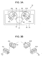
- FIG 3A and FIG. 3B are views each showing an arrangement of magnetic poles of the magnets 51 provided to the VCM 50 and an arrangement of magnetic poles of the magnets 61 provided to the position detecting portion 60, wherein FIG. 3A is a plan view of the shake correcting device 10 seeing from the light axis A2 direction and FIG 3B is a perspective view showing only the magnets 51 and 61.
- an arrangement of magnetic poles of the magnets 51 is when seeing the fixed portion 20 from the prism 2 side and an arrangement of magnetic poles of the magnets 61 is when seeing the moving portion 30 from the CCD 3 side.
- the magnet 51L of the VCM 50L is a multipole magnet formed to be in a rectangular parallelepiped shape.
- the magnet 51L is formed, as shown in FIG 2 and FIG 3, by superimposing in the direction of the light axis A2 two plate-shaped magnets, wherein the south pole and north pole are arranged to be mutually opposite directions along the drive direction D1 of the VCM 50L.
- the south pole is arranged at the closest part to the magnet 61L of the position detecting part 60L.
- the magnet 61L of the position detecting portion 60L is also a multipole magnet formed to be in a rectangular parallelepiped shape in the same way as the magnet 51L of the VCM 50L.
- the magnet 61 L is formed by superimposing in the light axis A2 direction two plate-shaped magnets, wherein the south pole and the north pole are arranged in the mutually opposite directions along the axis line direction D3 of a detection axis of the position detecting portion 60L. Also; in the magnet 61 L, the north pole is arranged to be close to the shake correcting lens 40 at the closest part to the magnet 51 L of the VCM 50L (refer to FIG. 3A and FIG 3B).
- the magnet 51R of the VCM 50R and the magnet 61R of the position detecting portion 60R respectively have the same structures as those of the magnet 51L and the magnet 61L, and an arrangement of the magnetic poles is in a plane symmetry with respect to a reference plane including the light axis A1 and the light axis A2.
- the north pole is arranged closer to the center side of the shake correcting device 10 than the south pole at a part closest to the magnet 51 R; and in the magnet 51R, the south pole is arranged at a part closest to the magnet 61R. Accordingly, between the magnet 51R and the magnet 61R, a rotation moment for rotating the moving portion 30 in the anticlockwise direction with respect to the fixed portion 20 is generated (refer to an arrow XR in FIG. 3A).
- the direction of the rotation moment generated between the magnet 5 1 L and the magnet 61 L becomes inverse of the direction of the rotation moment generated between the magnet 51 R and the magnet 61 R.
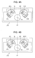
- FIG. 4A and FIG. 4B are views each showing an arrangement of magnetic poles of magnets in a shake correcting device of a comparative embodiment, wherein shake correcting devices of a first comparative embodiment and a second comparative embodiment are shown, respectively.
- a shake correcting device 210 of the first comparative embodiment shown in FIG 4A is provided with a magnet 261L having an inversed arrangement of a south pole and north pole instead of the magnet 61L of the first embodiment.
- a rotation moment generated between the magnet 51R and the magnet 61R (refer to an arrow XR in FIG 4A) is anticlockwise as same as in the first embodiment.
- the south pole is arranged closer to the center side of the shake correcting device 210 than the north pole, so that an anticlockwise rotation moment as same as the rotation moment generated between the magnet 51 R and the magnet 61 R is generated between the magnet 51 L and the magnet 261L (refer to an arrow XL in FIG 4A).
- a shake correcting device 310 of a second comparative embodiment is provided with a magnet 361R having an inversed arrangement of a south pole and a north pole instead of the magnet 61 R of the first embodiment.
- directions of rotation moments respectively generated between two magnets arranged close to each other become the same (refer to arrows XL and XR in FIG 4B) in the same way as in the first comparative embodiment.
- FIG. 5A to FIG 5D are views each showing a relationship of an arrangement of magnetic poles of magnets and a direction of a rotation moment acting on the moving portion.
- a view on the left shows an arrangement of magnetic poles and a view on the right shows a state of the moving portion.
- FIG. 5A shows the shake correcting device 10 of the first embodiment.
- the shake correcting device 10 since directions of rotation moments respectively generated between magnets are inverse, the rotation moments are countered by each other and a rotation moment acting on the moving portion 30 is reduced.
- the moving portion 30 moves approximately in parallel with the light axis A1 toward the photographer side with respect to the fixed portion 20.
- FIG 5B shows the shake correcting device 210 of the first comparative embodiment.
- the directions of rotation moments respectively generated between magnets are the same and both of the directions are anticlockwise, so that a rotation moment for rotating in the anticlockwise direction acts on the moving portion 30 with respect to the fixed portion 20.
- a rotation center of the rotation moment is not on the light axis A2, so that a light axis of the shake correcting lens 40 becomes out of the light axis A2.
- FIG. 5C shows the shake correcting device 310 of the second comparative embodiment.
- an anticlockwise rotation moment acts on the moving portion 30, so that the moving portion 30 rotates anticlockwise with respect to the fixed portion 20 and a light axis of the shake correcting lens 40 becomes out of the light axis A2 in the same way as in the first comparative embodiment.
- FIG. 5D shows a shake correcting device 410 of the second embodiment, wherein directions of rotation moments respectively generated between magnets are inverse in the same way as in the first embodiment. Note that directions of the rotation moments respectively generated between magnets are opposite from those in the first embodiment.
- the position detecting portion 60 of the shake correcting device it becomes difficult for the position detecting portion 60 of the shake correcting device to accurately detect a position of the moving portion 30 with respect to the fixed portion 20 in a state where the rotation moment acts on the moving portion 30 in the same way as in the first comparative example and the second comparative example. Also, in the first comparative embodiment and the second comparative embodiment, when a rotation amount of the moving portion 30 is large, the magnets 61 and the hall element 62 become distant and position detection may become impossible by the position detecting portion 60.
- the shake correcting device 10 of the first embodiment and the shake correcting device 410 of the second embodiment the moving portion 30 moves approximately in parallel with the light axis A1, so that an output of the position detecting portion 60 can be easily corrected and position detection of the moving portion 30 can be accurately made. Also, since rotation of the moving portion 30 with respect to the fixed portion 20 can be reduced, it is not necessary to provide a rotation stopper, etc., alternately, a compact rotation stopper for handling a small rotation load may be used and the shake correcting devices 10 and 410 can be made compact.
- FIG. 6 is a view showing a shake correcting device 510 provided to a digital camera of a third embodiment and is a view corresponding to FIG 2B showing the shake correcting device 10 of the first embodiment.
- the digital camera of the third embodiment is provided with a shake correcting device 510 wherein an arrangement of magnets 51, coils 52 and yokes 53 is different from that in the shake correcting device 10 of the first embodiment.
- the VCM 550L (a VCM used for driving in the D 1 direction) of the shake correcting device 510 comprises a magnet 551L, a coil 552L and a yoke 553L.
- the magnet 551L is fixed to the moving portion 30 in a state of facing to the fixed portion 20.
- the coils 552L are fixed to the fixed portion 20 via the yoke 553L in a state of facing to the magnet 551L.
- the yoke 553L is fixed to the fixed portion in a state of facing to an opposite surface of a surface of the coils 552L facing to the magnet 551L.
- the magnet 551L is a multipole magnet as same as the magnet 51 of the first embodiment, wherein the north pole is arranged to be close to the magnet 61L of the position detecting portion 60L at a part facing to the yoke 553L.
- the yoke 553L is magnetized by the magnet 551L.
- the yoke 553L functions as a magnet, wherein the south pole is arranged at the closest part to the magnet 61L of the position detecting portion 60L, that is, in the same way as the magnet 51L of the first embodiment.
- a not shown yoke 553R provided to a not shown VCM 550R (a VCM used for driving in the D2 direction) is also magnetized by a magnet 551R of the VCM 550R and functions in the same way as the magnet 51R of the first embodiment.
- the shake correcting device 510 of the third embodiment is capable of preventing the moving portion 30 from rotating with respect to the fixed portion 20 by arranging the magnet 551 and the magnet 61 so as to balance out the rotation moments respectively generated between magnets. As a result, the shake correcting device 510 is capable of accurately detecting a position of the moving portion 30. Furthermore, in the shake correcting device 510 of the third embodiment, the coils 552 are provided to the fixed portion 20, so that handling of wiring, etc. is easier and a move of the moving portion 30 is smoother comparing with that in the first embodiment wherein the coil 52 is provided to the moving portion 30 side.
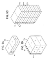
- FIG 9A is a perspective view showing the magnet 6 1 L, which is a multipole magnet formed to be in a rectangular parallelepiped shape by superimposing and bonding two plate-shaped magnets as explained above.
- the magnet 61L of this example is produced by casting or sintering ferrite or other magnetic body, then, processing the result to be in a desired shape and magnetizing to a south pole and a north pole. For preventing oxidization and scratches, plating processing of nickel, etc. is furthermore performed after the magnetization. Then, two plate-shaped magnets are superimposed and bonded, and on any one of six surfaces of the thus obtained magnet 61 L, a magnetic pole identification mark "M" is formed by an ink, etc. as shown in FIG. 9A.
- the mark “M” may be marked, for example, by an ink or paint in a different color from a surface color of the magnet 61 L or by emboss or a groove.
- the mark “M” may be a figure, such as a line, dot, triangle, square and circle, and two or more marks “M” may be given.
- FIG 9A in an operation of attaching the magnet 61L having a magnetic pole identification mark "M” thereon to the moving portion 30, a position of the magnetic pole identification mark "M” with respect to the moving portion 30 in accordance with an arrangement of the magnet poles is determined as an operation standard.
- Other magnets 61R, 5 1 L and 51R are also added with the same magnetic pole identification mark "M".
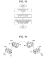
- magnetic pole identification marks "M” are formed on the magnets 61 L, 61 R, 51 L and 51 R as shown in FIG. 11.
- the magnetic pole identification marks "M” are identified by an operator or by an automatic assembling device, etc.
- Directions of magnetic poles of magnets can be identified by the magnetic pole identification marks "M", so that assembling with an erroneous direction of magnetic poles can be prevented.
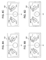
- FIG. 7A to FIG 7D and FIG 8A to FIG 8D are views showing shake correcting devices of embodiments and modified embodiments.
- FIG 7A shows the shake correcting device 10 of the first embodiments.
- the shake correcting device 600 in FIG 7B is provided with magnets 6 1 L-0 and 61R-0 each having an inversed arrangement of south and north poles comparing with that in the first embodiment.
- the shake correcting device 610 in FIG. 7C is provided with magnets 51L-1 and 51R-1 each having an inversed arrangement of south and north poles comparing with that in the first embodiment.
- the shake correcting device 620 in FIG. 7D is provided with magnets 51L-2 and 51R-2 and magnets 6 1 L-2 and 61R-2 each having an inversed arrangement of south and north poles comparing with that in the first embodiment.
- a shake correcting device 630 in FIG 8A is provided with magnets 51 L-3 and 6 1 L-3 each having an inversed arrangement of south and north poles comparing with that in the first embodiment.
- a shake correcting device 640 in FIG. 8B is provided with magnets 51 R-4 and 61R-4 each having an inversed arrangement of south and north poles comparing with that in the first embodiment.
- a shake correcting device 650 in FIG. 8C is provided with magnets 51L-5 and 61R-5 each having an inversed arrangement of south and north poles comparing with that in the first embodiment.
- a shake correcting device 660 in FIG. 8D is provided with magnets 51R-6 and 6 1 L-6 each having an inversed arrangement of south and north poles comparing with that in the first embodiment.
- magnets of the VCM were arranged on the fixed portion and magnets of the position detecting portion were arranged on the moving portion.
- an arrangement of these magnets is not limited to that and may be an inversed arrangement of the above case and the magnets of the VCM may be arranged on the moving portion and the magnets of the position detecting portion may be arranged on the fixed portion.
- magnets of the VCM and position detecting portion in the third embodiment were all arranged on the moving portion.
- an arrangement of the magnets is not limited to that and these magnets may be arranged on the fixed portion.
Landscapes
- Physics & Mathematics (AREA)
- General Physics & Mathematics (AREA)
- Optics & Photonics (AREA)
- Adjustment Of Camera Lenses (AREA)
- Studio Devices (AREA)
- Reciprocating, Oscillating Or Vibrating Motors (AREA)
Abstract
Description
- The disclosure of the
Japanese Patent Application No; 2006-173058 filed on June 22, 2006 - The present invention relates to a positioning device, a shake correcting device, electronics and a production method of the positioning device.
- A positioning device using a drive unit and a position detecting device is, for example, known as those installed in a camera, etc. (refer to the
Japanese Unexamined Patent Publication No. 2002-196382
A positioning device of the related art as above has had a disadvantage that positioning becomes difficult due to a rotation moment generated between a magnet provided to the drive unit and a magnet provided to the position detecting device. - An object of the present invention is to provide a positioning device having an improved positioning accuracy, a shake correcting device, electronics, and a production method of the positioning device.
- A positioning device of the present invention comprises a first member, a second member, a drive member, a first detection part and a second detection part.
A first member is provided with a first magnet arranged along a first axis and a second magnet arranged along a second axis intersecting with the first axis, and a second member is provided to face to the first member.
A drive member includes a first element provided to the first member and a second element provided to the second member and relatively drives the first member and the second member by an electromagnetic action between the first element and the second element.
A first detection portion detects a relative move of the first member and the second member with respect to the first axis direction in cooperation with the first magnet, and a second detection portion detects a relative move of the first member and the second member with respect to the second axis direction in cooperation with the second magnet.
The first magnet is arranged so as to reduce a rotation moment generated by an electromagnetic connection between the second magnet and the second element.
According to the positioning device of the present invention, a rotation moment generated between the second magnet and the second element is reduced so that the positioning accuracy is improved. - A production method of a positioning device of the present invention comprises the step of forming a mark that identifies magnetic poles on at least one of the first magnet and the second magnet and the step of attaching the magnet having the mark to the first member.
A production method of a positioning device according to another aspect of the present invention comprises the step of forming a mark that identifies magnetic poles on a drive magnet and the step of attaching the drive magnet having the mark to the first member or the second member.
According to a production method of a positioning device of the present invention, magnetic poles of magnets can be easily identified, so that attaching with erroneous magnetic poles can be prevented. - These and other objects and features of the present invention will become clearer from the following description of the preferred embodiments given with reference to the attached drawings, in which:
- FIG. 1 is a perspective view showing a digital camera according to a first embodiment;
- FIG. 2A and FIG. 2B are views showing a shake correcting device installed in the digital camera shown in FIG. 1;
- FIG 3A and FIG. 3B are views showing an arrangement of magnetic poles of magnets provided to a VCM of the shake correcting device and an arrangement of magnetic poles of magnets provided to the position detecting part in FIG. 2A and FIG. 2B;
- FIG. 4A and FIG 4B are views each showing an arrangement of magnetic poles of magnets in a shake correcting device of a comparative embodiment;
- FIG. 5A to FIG 5D are views each showing a relationship between an arrangement of magnetic poles of magnets provided to a shake correcting device and a rotation moment acting on the moving portion in an embodiment or a comparative embodiment;
- FIG 6 is a view showing a shake correcting device according to a third embodiment;
- FIG 7A to FIG 7D are views each showing a shake correcting device of an embodiment or a modified embodiment;
- FIG. 8A to FIG. 8D are views each showing a shake correcting device of an embodiment or a modified embodiment;
- FIG. 9A and FIG 9B are perspective views each showing magnets in an embodiment;
- FIG. 9C is a perspective view showing an embodiment wherein marks are added to magnets;
- FIG 10 is a flowchart showing a production method of an embodiment; and
- FIG 11 is a view showing an arrangement of magnetic poles of magnets provided to a VCM of the shake correcting device in FIG 2A and FIG 2B and a positional relationship of an arrangement of magnetic poles of magnets provided to a position detecting portion and marks.
- Below, the present invention will be explained further in detail by using embodiments with reference to the drawings. Note that the embodiments below will be explained by taking an example of a digital camera as electronics.
- FIG 1 is a perspective view showing a digital camera according to first and second embodiments.
FIG. 2A and FIG. 2B are views showing a shake correcting device installed in the digital camera shown in FIG. 1, wherein FIG 2A is a plan view of the shake correcting device and FIG. 2B is a sectional view along IIB-IIB in FIG. 2A. - A digital camera 100 (hereinafter, referred to as a camera 100) is a camera with an unchangeable lens and comprises a
body 110 and alens barrel 120.
Thebody 110 is a box-shaped container having a space inside and is formed to be an approximately rectangular parallelepiped shape, for example, made by a synthetic resin and a metal material, such as an aluminum alloy
Thelens tube 120 is held in the space inside thebody 110 and comprises afirst lens group 1, aprism 2, a CCD (Charge Coupled Device) 3 and ashake correcting device 10. A switch SW is a switch used, for example, for a shutter release operation and control of the shake correcting device, etc. The switch SW is provided on the opposite side of thefirst lens group 1 in thebody 110. A switch VRSW is a switch used for operating of activating or deactivating the shake correcting device. The switch VRSW is provided on the opposite side of thefirst lens group 1 in thebody 110. - The
first lens group 1 is provided to the closest side to a subject of shooting in an image pickup optical system held in thelens tube 120. Thefirst lens group 1 is arranged on a plane facing to a subject among planes of thebody 110 in a state that the incident surface is exposed.
Theprism 2 is arranged on the emitting side of thefirst lens group 1 inside thebody 110 and is a right angle prism for totally reflecting a light emitted from thefirst lens group 1 to bend the direction, for example, by 90°.
Below, an image pickup optical system of thecamera 100 will be explained by giving reference numbers A1 and A2 to a light axis on the incident side and a light axis on the emitting side of theprism 2, respectively. - The
CCD 3 is a photoelectric conversion element for converting a subject image light obtained by the image pickup optical system of thecamera 100 including thefirst lens group 1 to an electric signal. TheCCD 3 is arranged on the emitting side of theprism 2 and vertically below theprism 2 in a normal shooting position of thecamera 100. Note that, in thecamera 100, for example, a CMOS (Complementary Metal Oxide Semiconductor), etc. may be used as its image pickup device.
Here, in the present specification, the normal shooting position of thecamera 100 indicates a posture of thecamera 100 when shooting a landscape-oriented image by setting the optical axis A1 approximately horizontal.
An image pickup surface of theCCD 3 becomes approximately horizontal in a state that thecamera 100 is at the normal shooting position.
Note that, while omitted in FIG 1, thelens tube 120 is provided with a plurality of lens groups including a zoom lens and a focus lens between thefirst lens group 1 and theprism 2 and between theprism 2 and theCCD 3. - The
shake correcting device 10 is arranged on the light axis A2 between theprism 2 and theCCD 3.
Theshake correcting device 10 comprises, as shown in FIG. 2A and FIG. 2B, a fixedportion 20, a movingportion 30, ashake correcting lens 40, a voice coil motor 50 (hereinafter, also referred to as a VCM50), a position detecting portion 60 and asteel ball 70.
Here, an arrangement of respective elements provided to theshake correcting device 10 will be explained based on a state where the movingportion 30 is placed to be at the center with respect to the fixedportion 20. The state where the movingportion 30 is placed to be at the center indicates the state where a light axis of theshake correcting lens 40 substantially matches with the light axis A2 of theshake correcting lens 40.
Theshake correcting device 10 is for reducing an influence of shaking, etc. at shooting by detecting an inclination angle of thecamera 100 by agyro sensor 4 fixed to inside of thebody 110 shown in FIG. 1 and moving theshake correcting lens 40 by driving the movingportion 30 with respect to the fixedportion 20 on a plane perpendicular to the light axis A2 in accordance with the inclination angle by the VCM 50. Driving of the VCM 50 is controlled by acontrol device 5 shown in FIG 1. - The fixed
portion 20 is a base of theshake correcting device 10 fixed to thelens tube 120. The movingportion 30 is supported to be movable on a plane perpendicular to the light axis A2 with respect to the fixedportion 20. The movingportion 30 is arranged on the closer side to theprism 2 than the fixedportion 20.
The fixedportion 20 and the movingportion 30 are, as shown in FIG. 2, formed to be an approximately rectangular plate shape when seeing from the light axis A2 direction, wherein a size in the direction perpendicular to the light axis A1 and the light axis A2 (The right and left direction in FIG. 2A. Hereinafter, it will be also referred to as a longitudinal direction.) is longer than a size in the direction in parallel with the light axis A1 (the up and down direction in FIG. 2A).
Theshake correcting lens 40 is attached to a region on the photographer's side of the movingportion 30 and at the approximately center portion in the longitudinal direction. - The voice coil motor 50 is an electromagnetic actuator for driving the moving
portion 30 on a plane perpendicular to the light axis A2 with respect to the fixedportion 20.
The VCM 50 is arranged by a pair sandwiching theshake correcting lens 40 and away from each other in the longitudinal direction of the fixedportion 20 and the movingportion 30.
Below, the VCM 50, a later explained position detecting portion 60, and elements included therein will be explained by adding "R" to reference numbers of those arranged on the right side of the light axis A2 and "L" to reference numbers of those arranged on the left side.
Driving directions (thrust directions) D1 and D2 of the movingportion 30 by theVCM 50L andVCM 50R are, for example, oblique by 45° with respect to the longitudinal direction of the fixedportion 20 and the movingportion 30, respectively. There is an effect of simplifying calculations relating to the trigonometric function when the oblique angle is 45°. However, it does not have to be 45°.
Here, when assuming that an axis line passing through theVCM 50L and in parallel with the driving direction D1 is a drive axis line DL and that an axis line passing through theVCM 50R and in parallel with the driving direction D2 is a drive axis line DR, a crossing point of the drive axis line DL and the drive axis line DR is arranged on a plane including the light axis A1 and the light axis A2 and on a region closer to the subject of shooting than the light axis A2. - The
VCM 50L comprises, as shown in FIG 2B, amagnet 51L, acoil 52L and ayoke 53L.
Themagnet 51L is a permanent magnet fixed to the fixedportion 20 in a state of facing to the movingportion 30. An arrangement of the magnet poles of themagnet 51L (andmagnet 51 R) will be explained in detail later on.
Thecoil 52L is an electric winding fixed to the movingportion 30 in a state of facing to themagnet 51 L.
Theyoke 53L is a magnetic material formed, for example, by a steel based metal material, etc. to be in a plate shape. Theyoke 53L is fixed to the movingportion 30 in a state of facing to the opposite surface of a surface of thecoil 52L facing to themagnet 51 L.
TheVCM 50R also has the same structure as that of theVCM 50L explained above. - The position detecting portion 60 is a position sensor for detecting a position of the moving
portion 30 within a plane perpendicular to the light axis A2 with respect to the fixedportion 20.
The position detecting portion 60 is arranged in a pair being away from each other in the longitudinal direction of the fixedportion 20 and the movingportion 30 and on both sides of a plane including the light axis A1 and the light axis A2 in the same way as the VCM 50. Theseposition detecting portions VCM shake correcting device 10.
Theposition detecting portion 60L is arranged next to theVCM 50L, and an axis line direction D3 of the detection axis is in parallel with the driving direction D2 of theVCM 50R.
On the other hand, theposition detecting portion 60R is arranged next to theVCM 50R, and an axis line direction D4 of the detection axis is in parallel with the driving direction D1 of theVCM 50L.
Also, theposition detecting portions shake correcting lens 40. - The
position detecting portion 60L is provided with amagnet 61L and ahall element 62L.
Themagnet 61L is a permanent magnet fixed to the movingportion 30 in a state of facing to the fixedportion 20. An arrangement of magnetic poles of themagnet 6 1 L (andmagnet 61 R) will be explained in detail later on.
Thehall element 62L is a magnetic sensor fixed to the fixedportion 20 in a state of facing to themagnet 61L. Thehall element 62L is for detecting a change of a magnetic field of themagnet 61 L in accordance with a displacement of the movingportion 30 with respect to the fixedportion 20.
Note that theposition detecting portion 60R has the same structure as that of theposition detecting portion 60L explained above. - The
steel balls 70 are rolling elements for supporting the movingportion 30 to be movable within a plane perpendicular to the light axis A2 with respect to the fixedportion 20.
Each of thesteel balls 70 is held in a recessedportion 21 of the fixedportion 20, formed on a surface portion thereof facing to the movingportion 30, and held by being sandwiched between a bottom surface of the recessedportion 21 and the facing surface of the movingportion 30.
Thesteel balls 70 are provided, for example, by the number of three as shown in FIG. 2A. One of thesteel balls 70 is arranged at an end portion on the subject side of theshake correcting device 10, which is approximately the center of the fixedportion 30 in the longitudinal direction. Also, other twosteel balls 70 are respectively arranged at the end portion on the subject side of theshake correcting device 10, being close to longitudinal right and left end portions of the fixedportion 20.
Note that the movingportion 30 is kept free from dropping out from the fixedportion 20 because themagnets portion 20 magnetically attract theyokes 53L and 53R fixed to the movingportion 30 side facing thereto. - Next, an arrangement of magnetic poles of the magnets 51 provided to the VCM 50 and an arrangement of magnetic poles of the magnets 61 provided to the position detecting portion 60 will be explained.
FIG 3A and FIG. 3B are views each showing an arrangement of magnetic poles of the magnets 51 provided to the VCM 50 and an arrangement of magnetic poles of the magnets 61 provided to the position detecting portion 60, wherein FIG. 3A is a plan view of theshake correcting device 10 seeing from the light axis A2 direction and FIG 3B is a perspective view showing only the magnets 51 and 61.
Note that, in FIG 3A, an arrangement of magnetic poles of the magnets 51 is when seeing the fixedportion 20 from theprism 2 side and an arrangement of magnetic poles of the magnets 61 is when seeing the movingportion 30 from theCCD 3 side.
Themagnet 51L of theVCM 50L is a multipole magnet formed to be in a rectangular parallelepiped shape.
Themagnet 51L is formed, as shown in FIG 2 and FIG 3, by superimposing in the direction of the light axis A2 two plate-shaped magnets, wherein the south pole and north pole are arranged to be mutually opposite directions along the drive direction D1 of theVCM 50L.
Also, in themagnet 51L, the south pole is arranged at the closest part to themagnet 61L of theposition detecting part 60L. - The
magnet 61L of theposition detecting portion 60L is also a multipole magnet formed to be in a rectangular parallelepiped shape in the same way as themagnet 51L of theVCM 50L.
Themagnet 61 L is formed by superimposing in the light axis A2 direction two plate-shaped magnets, wherein the south pole and the north pole are arranged in the mutually opposite directions along the axis line direction D3 of a detection axis of theposition detecting portion 60L.
Also; in themagnet 61 L, the north pole is arranged to be close to theshake correcting lens 40 at the closest part to themagnet 51 L of theVCM 50L (refer to FIG. 3A and FIG 3B). - The
magnet 51R of theVCM 50R and themagnet 61R of theposition detecting portion 60R respectively have the same structures as those of themagnet 51L and themagnet 61L, and an arrangement of the magnetic poles is in a plane symmetry with respect to a reference plane including the light axis A1 and the light axis A2. - Next, an effect of the
shake correcting device 10 of the first embodiment will be explained by comparing with comparative embodiments.
Note that, in the comparative embodiments and other embodiments explained below, parts having the same function as that in the first and second embodiments explained above are given the same reference number or added with a common reference number at their tail ends, so that overlapping explanations and drawings are omitted appropriately.
As shown in FIG: 3A, in themagnet 61L, the north pole is arranged closer to the center side of theshake correcting device 10 than the south pole at the closest part to themagnet 51L; and in themagnet 51L, the south pole is arranged at the closest part to themagnet 61 L.
Accordingly, due to an attraction force and a repulsive force generated between themagnet 51L and themagnet 61 L, when seeing theshake correcting device 10 from theprism 2 side, a rotation moment for rotating the movingportion 30 in the clockwise direction with respect to the fixedportion 20 is generated between themagnet 51L and themagnet 6 1 L (refer to an arrow XL in FIG 3A). - On the other hand, as shown in FIG 3A, in the
magnet 61R, the north pole is arranged closer to the center side of theshake correcting device 10 than the south pole at a part closest to themagnet 51 R; and in themagnet 51R, the south pole is arranged at a part closest to themagnet 61R.
Accordingly, between themagnet 51R and themagnet 61R, a rotation moment for rotating the movingportion 30 in the anticlockwise direction with respect to the fixedportion 20 is generated (refer to an arrow XR in FIG. 3A).
As explained above, in theshake correcting device 10 in the first embodiment, the direction of the rotation moment generated between themagnet 5 1 L and themagnet 61 L becomes inverse of the direction of the rotation moment generated between themagnet 51 R and themagnet 61 R. - Here, as a comparative embodiment of the
shake correcting device 10 of the first embodiment, for example, a shake correcting device wherein an arrangement of the magnetic poles of the magnets 61 is inverse of that in the first embodiment will be considered.
FIG. 4A and FIG. 4B are views each showing an arrangement of magnetic poles of magnets in a shake correcting device of a comparative embodiment, wherein shake correcting devices of a first comparative embodiment and a second comparative embodiment are shown, respectively.
Ashake correcting device 210 of the first comparative embodiment shown in FIG 4A is provided with amagnet 261L having an inversed arrangement of a south pole and north pole instead of themagnet 61L of the first embodiment.
In theshake correcting device 210 of the first comparative embodiment, a rotation moment generated between themagnet 51R and themagnet 61R (refer to an arrow XR in FIG 4A) is anticlockwise as same as in the first embodiment.
On the other hand, in themagnet 261 L, the south pole is arranged closer to the center side of theshake correcting device 210 than the north pole, so that an anticlockwise rotation moment as same as the rotation moment generated between themagnet 51 R and themagnet 61 R is generated between themagnet 51 L and themagnet 261L (refer to an arrow XL in FIG 4A). - A
shake correcting device 310 of a second comparative embodiment is provided with amagnet 361R having an inversed arrangement of a south pole and a north pole instead of themagnet 61 R of the first embodiment.
In theshake correcting device 310 of the second comparative embodiment, directions of rotation moments respectively generated between two magnets arranged close to each other become the same (refer to arrows XL and XR in FIG 4B) in the same way as in the first comparative embodiment. - In each of the
shake correcting devices portion 30 with respect to the fixedportion 20 is generated by combining the two rotation moments.
FIG. 5A to FIG 5D are views each showing a relationship of an arrangement of magnetic poles of magnets and a direction of a rotation moment acting on the moving portion. In each of FIG. 5A to FIG 5D, a view on the left shows an arrangement of magnetic poles and a view on the right shows a state of the moving portion.
FIG. 5A shows theshake correcting device 10 of the first embodiment.
In theshake correcting device 10, since directions of rotation moments respectively generated between magnets are inverse, the rotation moments are countered by each other and a rotation moment acting on the movingportion 30 is reduced. In theshake correcting device 10 of the first embodiment, the movingportion 30 moves approximately in parallel with the light axis A1 toward the photographer side with respect to the fixedportion 20. - FIG 5B shows the
shake correcting device 210 of the first comparative embodiment.
In theshake correcting device 210, the directions of rotation moments respectively generated between magnets are the same and both of the directions are anticlockwise, so that a rotation moment for rotating in the anticlockwise direction acts on the movingportion 30 with respect to the fixedportion 20.
Also, a rotation center of the rotation moment is not on the light axis A2, so that a light axis of theshake correcting lens 40 becomes out of the light axis A2. - FIG. 5C shows the
shake correcting device 310 of the second comparative embodiment.
In theshake correcting device 310, an anticlockwise rotation moment acts on the movingportion 30, so that the movingportion 30 rotates anticlockwise with respect to the fixedportion 20 and a light axis of theshake correcting lens 40 becomes out of the light axis A2 in the same way as in the first comparative embodiment.
FIG. 5D shows ashake correcting device 410 of the second embodiment, wherein directions of rotation moments respectively generated between magnets are inverse in the same way as in the first embodiment. Note that directions of the rotation moments respectively generated between magnets are opposite from those in the first embodiment.
In theshake correcting device 410, rotation moments for acting on the movingportion 30 are countered by each other in the same way as in theshake correcting device 10 of the first embodiment and the movingportion 30 moves approximately in parallel with the light axis A1 to the subject side with respect to the fixedportion 20. - Here, it becomes difficult for the position detecting portion 60 of the shake correcting device to accurately detect a position of the moving
portion 30 with respect to the fixedportion 20 in a state where the rotation moment acts on the movingportion 30 in the same way as in the first comparative example and the second comparative example.
Also, in the first comparative embodiment and the second comparative embodiment, when a rotation amount of the movingportion 30 is large, the magnets 61 and the hall element 62 become distant and position detection may become impossible by the position detecting portion 60.
On the other hand, theshake correcting device 10 of the first embodiment and theshake correcting device 410 of the second embodiment, the movingportion 30 moves approximately in parallel with the light axis A1, so that an output of the position detecting portion 60 can be easily corrected and position detection of the movingportion 30 can be accurately made.
Also, since rotation of the movingportion 30 with respect to the fixedportion 20 can be reduced, it is not necessary to provide a rotation stopper, etc., alternately, a compact rotation stopper for handling a small rotation load may be used and theshake correcting devices - Next, a digital camera as a third embodiment of electronics will be explained.
FIG. 6 is a view showing ashake correcting device 510 provided to a digital camera of a third embodiment and is a view corresponding to FIG 2B showing theshake correcting device 10 of the first embodiment.
The digital camera of the third embodiment is provided with ashake correcting device 510 wherein an arrangement of magnets 51, coils 52 and yokes 53 is different from that in theshake correcting device 10 of the first embodiment. - The
VCM 550L (a VCM used for driving in theD 1 direction) of theshake correcting device 510 comprises amagnet 551L, acoil 552L and ayoke 553L.
Themagnet 551L is fixed to the movingportion 30 in a state of facing to the fixedportion 20.
Thecoils 552L are fixed to the fixedportion 20 via theyoke 553L in a state of facing to themagnet 551L.
Theyoke 553L is fixed to the fixed portion in a state of facing to an opposite surface of a surface of thecoils 552L facing to themagnet 551L.
Themagnet 551L is a multipole magnet as same as the magnet 51 of the first embodiment, wherein the north pole is arranged to be close to themagnet 61L of theposition detecting portion 60L at a part facing to theyoke 553L.
Here, in theshake correcting device 510, theyoke 553L is magnetized by themagnet 551L. As a result, theyoke 553L functions as a magnet, wherein the south pole is arranged at the closest part to themagnet 61L of theposition detecting portion 60L, that is, in the same way as themagnet 51L of the first embodiment.
A not shown yoke 553R provided to a not shown VCM 550R (a VCM used for driving in the D2 direction) is also magnetized by a magnet 551R of the VCM 550R and functions in the same way as themagnet 51R of the first embodiment. - As explained above, the
shake correcting device 510 of the third embodiment is capable of preventing the movingportion 30 from rotating with respect to the fixedportion 20 by arranging the magnet 551 and the magnet 61 so as to balance out the rotation moments respectively generated between magnets. As a result, theshake correcting device 510 is capable of accurately detecting a position of the movingportion 30.
Furthermore, in theshake correcting device 510 of the third embodiment, the coils 552 are provided to the fixedportion 20, so that handling of wiring, etc. is easier and a move of the movingportion 30 is smoother comparing with that in the first embodiment wherein the coil 52 is provided to the movingportion 30 side. - In the shake correcting devices of the embodiments, a direction of arranging magnetic poles of the
magnets magnets magnets
Themagnet 61L shown in FIG 3B will be taken as an example for the explanation. FIG 9A is a perspective view showing themagnet 6 1 L, which is a multipole magnet formed to be in a rectangular parallelepiped shape by superimposing and bonding
two plate-shaped magnets as explained above. Themagnet 61L of this example is produced by casting or sintering ferrite or other magnetic body, then, processing the result to be in a desired shape and magnetizing to a south pole and a north pole. For preventing oxidization and scratches, plating processing of nickel, etc. is furthermore performed after the magnetization.
Then, two plate-shaped magnets are superimposed and bonded, and on any one of six surfaces of the thus obtainedmagnet 61 L, a magnetic pole identification mark "M" is formed by an ink, etc. as shown in FIG. 9A. - When giving the magnetic pole identification mark "M", as shown in FIG. 9C, it is possible to give the marks in a short time by stacking a plurality of
magnets 61 L so that their directions of magnetic poles become the same and giving the marks at a time.
Note that, in the case of themagnet 61 L in a rectangular parallelepiped shape shown in FIG. 9A and FIG. 9B, a direction of magnetic poles of themagnet 61 L can be identified only by giving the magnetic pole identification mark "M" to any one of the six surfaces. However, the mark "M" may be given to two or more surfaces of themagnet 61L in a rectangular parallelepiped shape.
The mark "M" may be given at the center of a surface of themagnet 6 1 L or at the outlaying part. Also, the mark "M" may be marked, for example, by an ink or paint in a different color from a surface color of themagnet 61 L or by emboss or a groove. Alternately, the mark "M" may be a figure, such as a line, dot, triangle, square and circle, and two or more marks "M" may be given.
As shown in FIG 9A, in an operation of attaching themagnet 61L having a magnetic pole identification mark "M" thereon to the movingportion 30, a position of the magnetic pole identification mark "M" with respect to the movingportion 30 in accordance with an arrangement of the magnet poles is determined as an operation standard.Other magnets
Next, with reference to FIG 10, a production method of a positioning device of the present embodiment will be explained. In the production method of a positioning device of the present embodiment, first, magnetic pole identification marks "M" are formed on themagnets - The present invention is not limited to the embodiments explained above and may be variously modified and changed, and the modifications and changes are also included in the technical scope of the present invention.
- (1) The configurations of the positioning device, shake correcting device and electronics of the present invention are not limited to those in the embodiments and may be suitably modified. For example, electronics of the embodiments was a digital camera, but the electronics is not limited to that and may be, for example, a film camera, a video camera, a cellular phone, an interchangeable lens tube including a shake correcting device or an unchangeable lens tube integrally incorporated in a camera.
Also, the shake correcting devices of the embodiments were a lens shift type for driving a shake correcting lens on a plane perpendicular to a light axis, however, the present invention is not limited to that and may be a type of attaching an image pickup element, such as a CCD, to the moving portion and shifting the image pickup element. - (2) An arrangement of magnetic poles of magnets provided to a shake correcting device of embodiments is not limited to those of the above embodiments as far as it can balance out rotation moments generated between closely arranged magnets.
FIG. 7A to FIG 7D and FIG 8A to FIG 8D are views showing shake correcting devices of embodiments and modified embodiments.
FIG 7A shows theshake correcting device 10 of the first embodiments.
Instead of themagnets shake correcting device 10 of the first embodiment shown in FIG. 7A, theshake correcting device 600 in FIG 7B is provided withmagnets 6 1 L-0 and 61R-0 each having an inversed arrangement of south and north poles comparing with that in the first embodiment.
Instead of themagnets 5 1 L and 51R in theshake correcting device 10 of the first embodiment shown in FIG. 7A, theshake correcting device 610 in FIG. 7C is provided withmagnets 51L-1 and 51R-1 each having an inversed arrangement of south and north poles comparing with that in the first embodiment.
Instead of themagnets 5 1 L and 51 R andmagnets shake correcting device 10 of the first embodiment shown in FIG. 7A, theshake correcting device 620 in FIG. 7D is provided withmagnets 51L-2 and 51R-2 andmagnets 6 1 L-2 and 61R-2 each having an inversed arrangement of south and north poles comparing with that in the first embodiment.
As shown in FIG 7A to FIG 7D, in theshake correcting devices - Instead of the
magnets shake correcting device 10 of the first embodiment shown in FIG. 7A, ashake correcting device 630 in FIG 8A is provided withmagnets 51 L-3 and 6 1 L-3 each having an inversed arrangement of south and north poles comparing with that in the first embodiment.
Instead of themagnets shake correcting device 10 of the first embodiment shown in FIG. 7A, ashake correcting device 640 in FIG. 8B is provided withmagnets 51 R-4 and 61R-4 each having an inversed arrangement of south and north poles comparing with that in the first embodiment.
Instead of themagnets shake correcting device 10 of the first embodiment shown in FIG. 7A, ashake correcting device 650 in FIG. 8C is provided withmagnets 51L-5 and 61R-5 each having an inversed arrangement of south and north poles comparing with that in the first embodiment.
Instead of themagnets shake correcting device 10 of the first embodiment shown in FIG 7A, ashake correcting device 660 in FIG. 8D is provided withmagnets 51R-6 and 6 1 L-6 each having an inversed arrangement of south and north poles comparing with that in the first embodiment.
In each of the shake correcting devices shown in FIG 7A to FIG. 7D and FIG 8A to FIG. 8D explained above, directions of rotation moments respectively generated between closely arranged magnets become inverse, so that the same effects as those in the shake correcting device of the embodiment can be obtained. - (3) In the first embodiment, magnets of the VCM were arranged on the fixed portion and magnets of the position detecting portion were arranged on the moving portion. However, an arrangement of these magnets is not limited to that and may be an inversed arrangement of the above case and the magnets of the VCM may be arranged on the moving portion and the magnets of the position detecting portion may be arranged on the fixed portion.
Also, magnets of the VCM and position detecting portion in the third embodiment were all arranged on the moving portion. However, an arrangement of the magnets is not limited to that and these magnets may be arranged on the fixed portion.
Claims (35)
- A positioning device, comprising:a first member provided with a first magnet arranged along a first axis and a second magnet arranged along a second axis intersecting with said first axis;a second member provided to face to said first member;a drive member including a first element provided to said first member and a second element provided to said second member, that relatively drives said first member and said second member by an electromagnetic action between said first element and said second element;a first detection portion that detects a relative move of said first member and said second member with respect to said first axis direction in cooperation with said first magnet;a second detection portion that detects a relative move of said first member and said second member with respect to said second axis direction in cooperation with said second magnet;wherein said first magnet is arranged so as to reduce a rotation moment generated by an electromagnetic connection between said second magnet and said second element.
- The positioning device as set forth in claim 1, wherein:said second element comprises a first drive magnet that generates a first rotation moment between itself and said first magnet and a second drive magnet that generates a second rotation moment including components in an inverse direction of a direction of said first rotation moment between itself and said second magnet.
- The positioning device as set forth in claim 2, wherein:said first magnet is provided to face to said first drive magnet and said second magnet is provided to face to said second drive magnet.
- The positioning device as set forth in claim 1, wherein:said second element comprises a first yoke that generates a first rotation moment between itself and said first magnet and a second yoke that generates a second rotation moment including components in an inverse direction of a direction of said first rotation moment between itself and said second magnet.
- The positioning device as set forth in claim 1, wherein:said second element comprises a first coil that generates a first rotation moment between itself and said first magnet and a second coil that generates a second rotation moment including components in an inverse direction of a direction of said first rotation moment between itself and said second magnet.
- A shake correcting device, comprising:the positioning device as set forth in claim 1; anda shake correcting optical system provided to one of said first member and said second member.
- A shake correcting device, comprising:the positioning device as set forth in claim 1; andan image pickup device provided to one of said first member and said second member.
- Electronics comprising the shake correcting device as set forth in claim 6.
- Electronics comprising the shake correcting device as set forth in claim 7.
- A production method of a positioning device comprising a first member and a second member being relatively movable to each other, comprising the steps of:forming a mark at a predetermined position of each magnet based on magnetic poles; andarranging magnets each having a mark thereon on at least one of said first member and said second member by using said marks.
- The production method of a positioning device as set forth in claim 10, comprising the step of performing plating processing on said magnets before the step of forming marks that identify magnetic poles on said magnets.
- The production method of a positioning device as set forth in claim 10, wherein said marks are formed in a state of superimposing a plurality of magnets.
- A production method of a positioning device comprising a first member and a second member being relatively movable to each other, comprising the steps of:marking at a predetermined position of a drive magnet that relatively drives said first member and said second member by an electromagnetic action between itself and a first element provided to one of said first member and said second member; andarranging said marked drive magnet on the other of said first member and said second member.
- The production method of a positioning device as set forth in claim 13, comprising the step of performing plating processing on said drive magnets before the step of forming marks that identify magnetic poles on said drive magnets.
- The production method of a positioning device as set forth in claim 13, wherein said marks are formed in a state of superimposing a plurality of drive magnets.
- The shake correcting device as set forth in claim 6, wherein:said drive member comprises a first drive member that generates a driving force in said second axis direction and a second drive member that generates a driving force in said first axis direction;said first drive member is provided to face to said first magnet; andsaid second drive member is provided to face to said second magnet.
- The shake correcting device as set forth in claim 16, comprising
an operation switch that activates a shake correcting operation:
wherein said first drive member and said first magnet are provided to a closer side to said operation switch than the center of said shake correcting optical system; and
said second drive member and said second magnet are provided on the opposite side of said side closer to said operation switch than the center of said shake correcting optical system. - The shake correcting device as set forth in claim 7, wherein:said drive member comprises a first drive member that generates a driving force in said second axis direction and a second drive member that generates a driving force in said first axis direction;said first drive member is provided to face to said first magnet; andsaid second drive member is provided to face to said second magnet.
- The shake correcting device as set forth in claim 18, comprising
an operation switch that activates a shake correcting operation:
wherein said first driving member and said first magnet are provided to a closer side to said operation switch than the center of said image pickup device; and
said second drive member and said second magnet are provided to the opposite side of said side closer to said operation switch than the center of said image pickup device. - The production method of a positioning device as set forth in claim 10, wherein
said magnet comprises a first magnet and a second magnet; and
the step of arranging a drive member that relatively drives said first member and said second member so as to face to said first magnet and said second magnet is included: - The production method of a positioning device as set forth in claim 20, wherein
a shake correcting lens is arranged on at least one of said first member and said second member by avoiding a position where said first magnet and said second magnet face to said drive member. - The production method of a positioning device as set forth in claim 20, wherein
said first magnet is arranged so as to reduce a rotation moment generated by an electromagnetic connection between said drive member and said second magnet. - A production method of a positioning device comprising a first member and a second member being relatively movable to each other, comprising the steps of:arranging on said first member a first magnet having a mark formed at a predetermined position thereon, so that the magnetic pole direction is along a first axis; and arranging on said first member a second magnet having a mark formed at a predetermined position thereon, so that the magnetic pole direction is along a second axis intersecting with said first axis; andarranging a drive member that relatively drives said first member and said second member so as to face to said first magnet and said second magnet.
- The production method of a positioning device as set forth in claim 23, wherein
said first magnet is arranged so as to reduce a rotation moment generated by an electromagnetic connection between said drive member and said second magnet. - The production method of a positioning device as set forth in claim 24, wherein
said drive member relatively drives said first member and said second member by an electromagnetic action between a first element provided to said first member and said second element provided to said second member. - The production method of a positioning device as set forth in claim 25, wherein
said first magnet is arranged so as to reduce a rotation moment generated by an electromagnetic connection between said second magnet and said second element. - The production method of a positioning device as set forth in claim 23, wherein
said marks are in a different color from a color of surfaces of said first magnet and said second magnet. - The production method of a positioning device as set forth in claim 23, wherein
said marks are marks that identify magnetic poles. - The production method of a positioning device as set forth in claim 23, comprising the steps of:providing a first detection portion that detects a relative move of said first member and said second member on said first axis direction with respect to said first magnet; andproviding a second detection portion that detects a relative move of said first member and said second member on said second axis direction with respect to said second magnet.
- The production method of a positioning device as set forth in claim 13, comprising the step of
arranging a first magnet on said first member so that a direction of magnetic poles thereof is along with a first axis, and arranging a second magnet on said first member so that a direction of magnetic poles thereof is along with a second axis intersecting with said first axis. - The production method of a positioning device as set forth in claim 30, comprising the step of forming a mark on at least one of said first magnet and said second magnet.
- The production method of a positioning device as set forth in claim 30, wherein
said drive magnet comprises a first drive magnet that generates a first rotation moment between itself and said first magnet and a second drive magnet that generates a second rotation moment including components in an inverse direction of a direction of said first rotation moment between itself and said second magnet. - The production method of a positioning device as set forth in claim 30, wherein
said first element comprises a first yoke that generates a first rotation moment between itself and said first magnet and a second yoke that generates a second rotation moment including components in an inverse direction of a direction of said first rotation moment between itself and said second magnet. - The production method of a positioning device as set forth in claim 13, wherein
said marks are in a different color from a color of surfaces of said drive magnet. - The production method of a positioning device as set forth in claim 13, wherein said marks are marks that identify magnetic poles.
Applications Claiming Priority (1)
| Application Number | Priority Date | Filing Date | Title |
|---|---|---|---|
| JP2006173058 | 2006-06-22 |
Publications (3)
| Publication Number | Publication Date |
|---|---|
| EP1871096A2 true EP1871096A2 (en) | 2007-12-26 |
| EP1871096A3 EP1871096A3 (en) | 2008-12-24 |
| EP1871096B1 EP1871096B1 (en) | 2012-12-12 |
Family
ID=38521681
Family Applications (1)
| Application Number | Title | Priority Date | Filing Date |
|---|---|---|---|
| EP07012159A Not-in-force EP1871096B1 (en) | 2006-06-22 | 2007-06-21 | Positioning device, shake correcting device and electronics |
Country Status (4)
| Country | Link |
|---|---|
| US (1) | US8073317B2 (en) |
| EP (1) | EP1871096B1 (en) |
| KR (1) | KR101404843B1 (en) |
| CN (1) | CN101093340B (en) |
Cited By (1)
| Publication number | Priority date | Publication date | Assignee | Title |
|---|---|---|---|---|
| WO2010101260A1 (en) | 2009-03-04 | 2010-09-10 | Ricoh Company, Ltd. | Shake correcting system, lens barrel, imaging device and hand-held data terminal |
Families Citing this family (24)
| Publication number | Priority date | Publication date | Assignee | Title |
|---|---|---|---|---|
| KR100988960B1 (en) * | 2008-04-23 | 2010-10-20 | 한국도로공사 | Bridge inspection robot capable of climbing over obstacles |
| TW201030370A (en) * | 2008-09-29 | 2010-08-16 | Nidec Copal Corp | Image blur correction device, imaging lens unit, and camera unit |
| WO2010038685A1 (en) * | 2008-09-30 | 2010-04-08 | 日本電産コパル株式会社 | Image blur correction device, imaging lens unit, and camera unit |
| JP5347193B2 (en) * | 2008-12-25 | 2013-11-20 | 株式会社タムロン | Anti-vibration actuator, lens unit and camera equipped with the same |
| US8792166B2 (en) * | 2009-01-14 | 2014-07-29 | Nidec Copal Corporation | Image blur correction apparatus and image pickup unit having image blur correction apparatus |
| KR101594296B1 (en) * | 2009-07-17 | 2016-02-16 | 삼성전자주식회사 | Image stabilizer |
| JP5846346B2 (en) * | 2009-08-21 | 2016-01-20 | ミツミ電機株式会社 | Camera shake correction device |
| JP5269143B2 (en) * | 2010-07-16 | 2013-08-21 | キヤノン株式会社 | Image blur correction apparatus, control method therefor, and imaging apparatus |
| JP5580684B2 (en) * | 2010-07-29 | 2014-08-27 | オリンパスイメージング株式会社 | Image stabilization apparatus and camera |
| JP2012032543A (en) * | 2010-07-29 | 2012-02-16 | Olympus Imaging Corp | Image blur correcting device and imaging device |
| US9172856B2 (en) * | 2011-03-29 | 2015-10-27 | Microsoft Technology Licensing, Llc | Folded imaging path camera |
| TW201323847A (en) * | 2011-12-13 | 2013-06-16 | Hon Hai Prec Ind Co Ltd | Method for testing spreading glue water of camera |
| JP5997992B2 (en) * | 2012-09-25 | 2016-09-28 | Hoya株式会社 | Imaging device |
| JP5797627B2 (en) * | 2012-09-25 | 2015-10-21 | Hoya株式会社 | Imaging device |
| JP6114050B2 (en) * | 2013-02-04 | 2017-04-12 | Hoya株式会社 | Imaging device |
| JP6114049B2 (en) * | 2013-02-04 | 2017-04-12 | Hoya株式会社 | Imaging device |
| US9703068B2 (en) * | 2013-04-19 | 2017-07-11 | Hong Kong Applied Science and Technology Research Institute, Co., Ltd. | Lens moving apparatus |
| CN104199234A (en) * | 2014-09-04 | 2014-12-10 | 成都凯裕电子电器有限公司 | Anti-jitter optical module installed on mobile terminal |
| JP6332212B2 (en) * | 2015-09-18 | 2018-05-30 | カシオ計算機株式会社 | Posture estimation apparatus, posture estimation method, and program |
| JP6321703B2 (en) * | 2016-03-04 | 2018-05-09 | ファナック株式会社 | Wire electrical discharge machine inspection system |
| EP4344000B1 (en) * | 2018-05-02 | 2025-04-02 | Honor Device Co., Ltd. | Protective circuit for camera of terminal |
| WO2020105348A1 (en) * | 2018-11-21 | 2020-05-28 | 富士フイルム株式会社 | Image-shake correction device, lens device, and image capture device |
| CN211741621U (en) * | 2019-03-28 | 2020-10-23 | 台湾东电化股份有限公司 | Optical element driving mechanism |
| JP7774424B2 (en) * | 2021-11-12 | 2025-11-21 | 旭化成エレクトロニクス株式会社 | Program, control device, imaging device, and control method |
Family Cites Families (16)
| Publication number | Priority date | Publication date | Assignee | Title |
|---|---|---|---|---|
| DE69313763T2 (en) | 1992-03-18 | 1998-04-09 | Citizen Watch Co Ltd | ELECTRONIC DEVICE WITH VIBRATION ALARM |
| JP2598497Y2 (en) * | 1992-06-17 | 1999-08-09 | 日立金属株式会社 | Vibration control actuator and vibration control device using this vibration control actuator |
| JP3355785B2 (en) | 1994-05-16 | 2002-12-09 | ソニー株式会社 | Driving mechanism of optical axis correction lens |
| JPH0815590A (en) * | 1994-06-29 | 1996-01-19 | Olympus Optical Co Ltd | Optical element positioning device |
| JPH10221728A (en) * | 1997-02-07 | 1998-08-21 | Canon Inc | Lens barrel with shake correction optical means |
| JP3869907B2 (en) | 1997-04-18 | 2007-01-17 | キヤノン株式会社 | Lens barrel and imaging device provided with the same |
| US6064827A (en) * | 1997-05-16 | 2000-05-16 | Canon Kabushiki Kaisha | Image stabilizer |
| KR100245626B1 (en) * | 1997-06-30 | 2000-02-15 | 강병호 | Keyboard tilting device for portable computer |
| JP3969927B2 (en) | 2000-04-06 | 2007-09-05 | キヤノン株式会社 | Lens barrel, photographing device, and observation device |
| JP3822434B2 (en) * | 2000-12-13 | 2006-09-20 | 株式会社リコー | Objective lens drive |
| JP4006178B2 (en) | 2000-12-25 | 2007-11-14 | キヤノン株式会社 | Lens barrel, photographing device and observation device |
| JP4778711B2 (en) * | 2004-01-30 | 2011-09-21 | Hoya株式会社 | Image blur correction device |
| US7502051B2 (en) * | 2004-03-08 | 2009-03-10 | Hoya Corporation | Anti-shake apparatus |
| JP4456911B2 (en) * | 2004-03-30 | 2010-04-28 | パイオニア株式会社 | Pickup device and recording medium driving device |
| JP3952207B2 (en) * | 2004-12-15 | 2007-08-01 | 株式会社タムロン | Actuator and lens unit and camera provided with the same |
| JP4844177B2 (en) | 2006-03-07 | 2011-12-28 | 株式会社ニコン | Blur correction device and camera |
-
2007
- 2007-06-13 KR KR1020070057813A patent/KR101404843B1/en not_active Expired - Fee Related
- 2007-06-15 US US11/812,176 patent/US8073317B2/en not_active Expired - Fee Related
- 2007-06-21 EP EP07012159A patent/EP1871096B1/en not_active Not-in-force
- 2007-06-22 CN CN2007101100967A patent/CN101093340B/en not_active Expired - Fee Related
Non-Patent Citations (1)
| Title |
|---|
| None |
Cited By (2)
| Publication number | Priority date | Publication date | Assignee | Title |
|---|---|---|---|---|
| WO2010101260A1 (en) | 2009-03-04 | 2010-09-10 | Ricoh Company, Ltd. | Shake correcting system, lens barrel, imaging device and hand-held data terminal |
| EP2404216A4 (en) * | 2009-03-04 | 2016-08-31 | Ricoh Co Ltd | Shake correcting system, lens barrel, imaging device and hand-held data terminal |
Also Published As
| Publication number | Publication date |
|---|---|
| CN101093340A (en) | 2007-12-26 |
| EP1871096B1 (en) | 2012-12-12 |
| US20070297781A1 (en) | 2007-12-27 |
| EP1871096A3 (en) | 2008-12-24 |
| US8073317B2 (en) | 2011-12-06 |
| KR20070121522A (en) | 2007-12-27 |
| KR101404843B1 (en) | 2014-06-09 |
| CN101093340B (en) | 2013-07-17 |
Similar Documents
| Publication | Publication Date | Title |
|---|---|---|
| EP1871096B1 (en) | Positioning device, shake correcting device and electronics | |
| KR102299752B1 (en) | Optical path folding element with extended two-degree-of-freedom rotation range | |
| US12007582B2 (en) | Reduced height penalty for folded camera | |
| KR101031857B1 (en) | Camera shake compensation device | |
| EP2267512B1 (en) | Image blur reduction device and camera | |
| US20120099201A1 (en) | Tilt-type anti-shake compensation structure for auto-focus module | |
| JP5308457B2 (en) | Voice coil motor for driving correction lens, camera shake correction device, interchangeable lens and optical device | |
| US20070242938A1 (en) | Image stabilizing unit lens unit, and imaging apparatus | |
| JP5909877B2 (en) | Imaging device | |
| JP2008287034A (en) | Actuator, manufacturing method thereof, imaging device, and portable electronic device | |
| US12276898B2 (en) | Camera module | |
| JP2003057707A (en) | Image stabilizer | |
| US7405888B2 (en) | Image taking apparatus | |
| JP5289994B2 (en) | Optical correction unit, lens barrel and imaging device | |
| JP2011027947A (en) | Optical unit | |
| CN107621739B (en) | Image shake correction device | |
| JP5181542B2 (en) | Blur correction device, electronic equipment | |
| JP2017046569A (en) | Actuator and lens barrel including the same | |
| CN114339026A (en) | Camera module and electronic apparatus | |
| JP2007114709A (en) | Image blur correction device |
Legal Events
| Date | Code | Title | Description |
|---|---|---|---|
| PUAI | Public reference made under article 153(3) epc to a published international application that has entered the european phase |
Free format text: ORIGINAL CODE: 0009012 |
|
| AK | Designated contracting states |
Kind code of ref document: A2 Designated state(s): AT BE BG CH CY CZ DE DK EE ES FI FR GB GR HU IE IS IT LI LT LU LV MC MT NL PL PT RO SE SI SK TR |
|
| AX | Request for extension of the european patent |
Extension state: AL BA HR MK YU |
|
| PUAL | Search report despatched |
Free format text: ORIGINAL CODE: 0009013 |
|
| AK | Designated contracting states |
Kind code of ref document: A3 Designated state(s): AT BE BG CH CY CZ DE DK EE ES FI FR GB GR HU IE IS IT LI LT LU LV MC MT NL PL PT RO SE SI SK TR |
|
| AX | Request for extension of the european patent |
Extension state: AL BA HR MK RS |
|
| 17P | Request for examination filed |
Effective date: 20090624 |
|
| AKX | Designation fees paid |
Designated state(s): AT BE BG CH CY CZ DE DK EE ES FI FR GB GR HU IE IS IT LI LT LU LV MC MT NL PL PT RO SE SI SK TR |
|
| 17Q | First examination report despatched |
Effective date: 20090814 |
|
| RAP1 | Party data changed (applicant data changed or rights of an application transferred) |
Owner name: NIKON CORPORATION |
|
| GRAP | Despatch of communication of intention to grant a patent |
Free format text: ORIGINAL CODE: EPIDOSNIGR1 |
|
| GRAS | Grant fee paid |
Free format text: ORIGINAL CODE: EPIDOSNIGR3 |
|
| GRAA | (expected) grant |
Free format text: ORIGINAL CODE: 0009210 |
|
| AK | Designated contracting states |
Kind code of ref document: B1 Designated state(s): AT BE BG CH CY CZ DE DK EE ES FI FR GB GR HU IE IS IT LI LT LU LV MC MT NL PL PT RO SE SI SK TR |
|
| REG | Reference to a national code |
Ref country code: GB Ref legal event code: FG4D |
|
| REG | Reference to a national code |
Ref country code: CH Ref legal event code: EP |
|
| REG | Reference to a national code |
Ref country code: AT Ref legal event code: REF Ref document number: 588825 Country of ref document: AT Kind code of ref document: T Effective date: 20121215 |
|
| REG | Reference to a national code |
Ref country code: IE Ref legal event code: FG4D |
|
| REG | Reference to a national code |
Ref country code: DE Ref legal event code: R096 Ref document number: 602007027261 Country of ref document: DE Effective date: 20130207 |
|
| PG25 | Lapsed in a contracting state [announced via postgrant information from national office to epo] |
Ref country code: ES Free format text: LAPSE BECAUSE OF FAILURE TO SUBMIT A TRANSLATION OF THE DESCRIPTION OR TO PAY THE FEE WITHIN THE PRESCRIBED TIME-LIMIT Effective date: 20130323 Ref country code: FI Free format text: LAPSE BECAUSE OF FAILURE TO SUBMIT A TRANSLATION OF THE DESCRIPTION OR TO PAY THE FEE WITHIN THE PRESCRIBED TIME-LIMIT Effective date: 20121212 Ref country code: SE Free format text: LAPSE BECAUSE OF FAILURE TO SUBMIT A TRANSLATION OF THE DESCRIPTION OR TO PAY THE FEE WITHIN THE PRESCRIBED TIME-LIMIT Effective date: 20121212 Ref country code: LT Free format text: LAPSE BECAUSE OF FAILURE TO SUBMIT A TRANSLATION OF THE DESCRIPTION OR TO PAY THE FEE WITHIN THE PRESCRIBED TIME-LIMIT Effective date: 20121212 |
|
| REG | Reference to a national code |
Ref country code: NL Ref legal event code: VDEP Effective date: 20121212 |
|
| REG | Reference to a national code |
Ref country code: AT Ref legal event code: MK05 Ref document number: 588825 Country of ref document: AT Kind code of ref document: T Effective date: 20121212 |
|
| REG | Reference to a national code |
Ref country code: LT Ref legal event code: MG4D |
|
| PG25 | Lapsed in a contracting state [announced via postgrant information from national office to epo] |
Ref country code: SI Free format text: LAPSE BECAUSE OF FAILURE TO SUBMIT A TRANSLATION OF THE DESCRIPTION OR TO PAY THE FEE WITHIN THE PRESCRIBED TIME-LIMIT Effective date: 20121212 Ref country code: GR Free format text: LAPSE BECAUSE OF FAILURE TO SUBMIT A TRANSLATION OF THE DESCRIPTION OR TO PAY THE FEE WITHIN THE PRESCRIBED TIME-LIMIT Effective date: 20130313 Ref country code: LV Free format text: LAPSE BECAUSE OF FAILURE TO SUBMIT A TRANSLATION OF THE DESCRIPTION OR TO PAY THE FEE WITHIN THE PRESCRIBED TIME-LIMIT Effective date: 20121212 |
|
| PG25 | Lapsed in a contracting state [announced via postgrant information from national office to epo] |
Ref country code: IS Free format text: LAPSE BECAUSE OF FAILURE TO SUBMIT A TRANSLATION OF THE DESCRIPTION OR TO PAY THE FEE WITHIN THE PRESCRIBED TIME-LIMIT Effective date: 20130412 Ref country code: SK Free format text: LAPSE BECAUSE OF FAILURE TO SUBMIT A TRANSLATION OF THE DESCRIPTION OR TO PAY THE FEE WITHIN THE PRESCRIBED TIME-LIMIT Effective date: 20121212 Ref country code: BE Free format text: LAPSE BECAUSE OF FAILURE TO SUBMIT A TRANSLATION OF THE DESCRIPTION OR TO PAY THE FEE WITHIN THE PRESCRIBED TIME-LIMIT Effective date: 20121212 Ref country code: AT Free format text: LAPSE BECAUSE OF FAILURE TO SUBMIT A TRANSLATION OF THE DESCRIPTION OR TO PAY THE FEE WITHIN THE PRESCRIBED TIME-LIMIT Effective date: 20121212 Ref country code: EE Free format text: LAPSE BECAUSE OF FAILURE TO SUBMIT A TRANSLATION OF THE DESCRIPTION OR TO PAY THE FEE WITHIN THE PRESCRIBED TIME-LIMIT Effective date: 20121212 Ref country code: BG Free format text: LAPSE BECAUSE OF FAILURE TO SUBMIT A TRANSLATION OF THE DESCRIPTION OR TO PAY THE FEE WITHIN THE PRESCRIBED TIME-LIMIT Effective date: 20130312 Ref country code: CZ Free format text: LAPSE BECAUSE OF FAILURE TO SUBMIT A TRANSLATION OF THE DESCRIPTION OR TO PAY THE FEE WITHIN THE PRESCRIBED TIME-LIMIT Effective date: 20121212 |
|
| PG25 | Lapsed in a contracting state [announced via postgrant information from national office to epo] |
Ref country code: RO Free format text: LAPSE BECAUSE OF FAILURE TO SUBMIT A TRANSLATION OF THE DESCRIPTION OR TO PAY THE FEE WITHIN THE PRESCRIBED TIME-LIMIT Effective date: 20121212 Ref country code: NL Free format text: LAPSE BECAUSE OF FAILURE TO SUBMIT A TRANSLATION OF THE DESCRIPTION OR TO PAY THE FEE WITHIN THE PRESCRIBED TIME-LIMIT Effective date: 20121212 Ref country code: PL Free format text: LAPSE BECAUSE OF FAILURE TO SUBMIT A TRANSLATION OF THE DESCRIPTION OR TO PAY THE FEE WITHIN THE PRESCRIBED TIME-LIMIT Effective date: 20121212 Ref country code: PT Free format text: LAPSE BECAUSE OF FAILURE TO SUBMIT A TRANSLATION OF THE DESCRIPTION OR TO PAY THE FEE WITHIN THE PRESCRIBED TIME-LIMIT Effective date: 20130412 |
|
| PLBE | No opposition filed within time limit |
Free format text: ORIGINAL CODE: 0009261 |
|
| STAA | Information on the status of an ep patent application or granted ep patent |
Free format text: STATUS: NO OPPOSITION FILED WITHIN TIME LIMIT |
|
| PG25 | Lapsed in a contracting state [announced via postgrant information from national office to epo] |
Ref country code: DK Free format text: LAPSE BECAUSE OF FAILURE TO SUBMIT A TRANSLATION OF THE DESCRIPTION OR TO PAY THE FEE WITHIN THE PRESCRIBED TIME-LIMIT Effective date: 20121212 |
|
| 26N | No opposition filed |
Effective date: 20130913 |
|
| PG25 | Lapsed in a contracting state [announced via postgrant information from national office to epo] |
Ref country code: CY Free format text: LAPSE BECAUSE OF FAILURE TO SUBMIT A TRANSLATION OF THE DESCRIPTION OR TO PAY THE FEE WITHIN THE PRESCRIBED TIME-LIMIT Effective date: 20121212 |
|
| PG25 | Lapsed in a contracting state [announced via postgrant information from national office to epo] |
Ref country code: IT Free format text: LAPSE BECAUSE OF FAILURE TO SUBMIT A TRANSLATION OF THE DESCRIPTION OR TO PAY THE FEE WITHIN THE PRESCRIBED TIME-LIMIT Effective date: 20121212 |
|
| REG | Reference to a national code |
Ref country code: DE Ref legal event code: R097 Ref document number: 602007027261 Country of ref document: DE Effective date: 20130913 |
|
| PG25 | Lapsed in a contracting state [announced via postgrant information from national office to epo] |
Ref country code: MC Free format text: LAPSE BECAUSE OF FAILURE TO SUBMIT A TRANSLATION OF THE DESCRIPTION OR TO PAY THE FEE WITHIN THE PRESCRIBED TIME-LIMIT Effective date: 20121212 |
|
| REG | Reference to a national code |
Ref country code: CH Ref legal event code: PL |
|
| REG | Reference to a national code |
Ref country code: IE Ref legal event code: MM4A |
|
| PG25 | Lapsed in a contracting state [announced via postgrant information from national office to epo] |
Ref country code: IE Free format text: LAPSE BECAUSE OF NON-PAYMENT OF DUE FEES Effective date: 20130621 Ref country code: CH Free format text: LAPSE BECAUSE OF NON-PAYMENT OF DUE FEES Effective date: 20130630 Ref country code: LI Free format text: LAPSE BECAUSE OF NON-PAYMENT OF DUE FEES Effective date: 20130630 |
|
| PG25 | Lapsed in a contracting state [announced via postgrant information from national office to epo] |
Ref country code: MT Free format text: LAPSE BECAUSE OF FAILURE TO SUBMIT A TRANSLATION OF THE DESCRIPTION OR TO PAY THE FEE WITHIN THE PRESCRIBED TIME-LIMIT Effective date: 20121212 |
|
| PG25 | Lapsed in a contracting state [announced via postgrant information from national office to epo] |
Ref country code: TR Free format text: LAPSE BECAUSE OF FAILURE TO SUBMIT A TRANSLATION OF THE DESCRIPTION OR TO PAY THE FEE WITHIN THE PRESCRIBED TIME-LIMIT Effective date: 20121212 |
|
| PG25 | Lapsed in a contracting state [announced via postgrant information from national office to epo] |
Ref country code: HU Free format text: LAPSE BECAUSE OF FAILURE TO SUBMIT A TRANSLATION OF THE DESCRIPTION OR TO PAY THE FEE WITHIN THE PRESCRIBED TIME-LIMIT; INVALID AB INITIO Effective date: 20070621 Ref country code: LU Free format text: LAPSE BECAUSE OF NON-PAYMENT OF DUE FEES Effective date: 20130621 |
|
| REG | Reference to a national code |
Ref country code: FR Ref legal event code: PLFP Year of fee payment: 10 |
|
| REG | Reference to a national code |
Ref country code: FR Ref legal event code: PLFP Year of fee payment: 11 |
|
| REG | Reference to a national code |
Ref country code: FR Ref legal event code: PLFP Year of fee payment: 12 |
|
| PGFP | Annual fee paid to national office [announced via postgrant information from national office to epo] |
Ref country code: DE Payment date: 20190612 Year of fee payment: 13 |
|
| PGFP | Annual fee paid to national office [announced via postgrant information from national office to epo] |
Ref country code: GB Payment date: 20190619 Year of fee payment: 13 |
|
| PGFP | Annual fee paid to national office [announced via postgrant information from national office to epo] |
Ref country code: FR Payment date: 20200512 Year of fee payment: 14 |
|
| REG | Reference to a national code |
Ref country code: DE Ref legal event code: R119 Ref document number: 602007027261 Country of ref document: DE |
|
| GBPC | Gb: european patent ceased through non-payment of renewal fee |
Effective date: 20200621 |
|
| PG25 | Lapsed in a contracting state [announced via postgrant information from national office to epo] |
Ref country code: GB Free format text: LAPSE BECAUSE OF NON-PAYMENT OF DUE FEES Effective date: 20200621 |
|
| PG25 | Lapsed in a contracting state [announced via postgrant information from national office to epo] |
Ref country code: DE Free format text: LAPSE BECAUSE OF NON-PAYMENT OF DUE FEES Effective date: 20210101 |
|
| PG25 | Lapsed in a contracting state [announced via postgrant information from national office to epo] |
Ref country code: FR Free format text: LAPSE BECAUSE OF NON-PAYMENT OF DUE FEES Effective date: 20210630 |