EP1871014B1 - Transmission power control method, and mobile communication system - Google Patents
Transmission power control method, and mobile communication system Download PDFInfo
- Publication number
- EP1871014B1 EP1871014B1 EP07019923.7A EP07019923A EP1871014B1 EP 1871014 B1 EP1871014 B1 EP 1871014B1 EP 07019923 A EP07019923 A EP 07019923A EP 1871014 B1 EP1871014 B1 EP 1871014B1
- Authority
- EP
- European Patent Office
- Prior art keywords
- section
- transmission power
- mobile station
- cell
- serving cell
- Prior art date
- Legal status (The legal status is an assumption and is not a legal conclusion. Google has not performed a legal analysis and makes no representation as to the accuracy of the status listed.)
- Active
Links
- 230000005540 biological transmission Effects 0.000 title claims abstract description 185
- 238000000034 method Methods 0.000 title claims abstract description 24
- 238000010295 mobile communication Methods 0.000 title claims description 46
- 238000012545 processing Methods 0.000 description 100
- 238000010586 diagram Methods 0.000 description 19
- 238000004891 communication Methods 0.000 description 14
- 238000012937 correction Methods 0.000 description 8
- 238000005259 measurement Methods 0.000 description 8
- 238000013507 mapping Methods 0.000 description 7
- 101000741965 Homo sapiens Inactive tyrosine-protein kinase PRAG1 Proteins 0.000 description 6
- 102100038659 Inactive tyrosine-protein kinase PRAG1 Human genes 0.000 description 6
- 230000007423 decrease Effects 0.000 description 6
- 108010003272 Hyaluronate lyase Proteins 0.000 description 5
- 230000008569 process Effects 0.000 description 4
- 230000008859 change Effects 0.000 description 2
- 238000012986 modification Methods 0.000 description 2
- 230000004048 modification Effects 0.000 description 2
- 230000004044 response Effects 0.000 description 2
- 230000000694 effects Effects 0.000 description 1
- 238000005516 engineering process Methods 0.000 description 1
- 230000011664 signaling Effects 0.000 description 1
- 230000007480 spreading Effects 0.000 description 1
Images


Classifications
-
- H—ELECTRICITY
- H04—ELECTRIC COMMUNICATION TECHNIQUE
- H04W—WIRELESS COMMUNICATION NETWORKS
- H04W52/00—Power management, e.g. TPC [Transmission Power Control], power saving or power classes
- H04W52/04—TPC
- H04W52/30—TPC using constraints in the total amount of available transmission power
- H04W52/32—TPC of broadcast or control channels
- H04W52/325—Power control of control or pilot channels
-
- H—ELECTRICITY
- H04—ELECTRIC COMMUNICATION TECHNIQUE
- H04W—WIRELESS COMMUNICATION NETWORKS
- H04W52/00—Power management, e.g. TPC [Transmission Power Control], power saving or power classes
- H04W52/04—TPC
- H04W52/06—TPC algorithms
- H04W52/16—Deriving transmission power values from another channel
-
- H—ELECTRICITY
- H04—ELECTRIC COMMUNICATION TECHNIQUE
- H04B—TRANSMISSION
- H04B7/00—Radio transmission systems, i.e. using radiation field
- H04B7/24—Radio transmission systems, i.e. using radiation field for communication between two or more posts
- H04B7/26—Radio transmission systems, i.e. using radiation field for communication between two or more posts at least one of which is mobile
- H04B7/2612—Arrangements for wireless medium access control, e.g. by allocating physical layer transmission capacity
-
- H—ELECTRICITY
- H04—ELECTRIC COMMUNICATION TECHNIQUE
- H04W—WIRELESS COMMUNICATION NETWORKS
- H04W52/00—Power management, e.g. TPC [Transmission Power Control], power saving or power classes
- H04W52/04—TPC
- H04W52/30—TPC using constraints in the total amount of available transmission power
- H04W52/36—TPC using constraints in the total amount of available transmission power with a discrete range or set of values, e.g. step size, ramping or offsets
-
- H—ELECTRICITY
- H04—ELECTRIC COMMUNICATION TECHNIQUE
- H04W—WIRELESS COMMUNICATION NETWORKS
- H04W52/00—Power management, e.g. TPC [Transmission Power Control], power saving or power classes
- H04W52/04—TPC
- H04W52/38—TPC being performed in particular situations
- H04W52/40—TPC being performed in particular situations during macro-diversity or soft handoff
Definitions
- the present invention relates to a transmission power control method and a mobile communication system for controlling a transmission power of an absolute transmission rate control channel including an absolute transmission rate of uplink user data, which is transmitted from a cell controlled by a radio base station to a mobile station.
- a radio network controller RNC when setting a Dedicated Physical Channel (DPCH) between a mobile station UE and a radio base station Node B, a radio network controller RNC is configured to determine a transmission rate of uplink user data, in consideration of hardware resources for receiving of the radio base station Node B (hereinafter, hardware resource), a radio resource in an uplink (an interference volume in an uplink), a transmission power of the mobile station UE, a transmission processing performance of the mobile station UE, a transmission rate required for an upper application, or the like, and to notify the determined transmission rate of the uplink user data by a message of a layer-3 (Radio Resource Control Layer) to both of the mobile station UE and the radio base station Node B.
- a layer-3 Radio Resource Control Layer
- the radio network controller RNC is provided at an upper level of the radio base station Node B, and is an apparatus configured to control the radio base station Node B and the mobile station UE.
- the radio network controller RNC integrally controls a plurality of radio base stations Node B in general. Therefore, in the conventional mobile communication system, there has been a problem that it is difficult to perform fast control for changing of the transmission rate of uplink user data (for example, per approximately 1 through 100 ms), due to the increase of processing load and processing delay in the radio network controller RNC.
- control for changing of the transmission rate of the uplink user data is generally performed on the order from a few hundred ms to a few seconds.
- the data are transmitted by accepting low-speed, high-delay, and low-transmission efficiency as shown in FIG. 2B , or, as shown in FIG. 2C , by reserving radio resources for high-speed communications to accept that radio bandwidth resources in an unoccupied state and hardware resources in the radio base station Node B are wasted.
- the 3rd Generation Partnership Project (3GPP) and the 3rd Generation Partnership Project 2 (3GPP2) which are international standardization organizations of the third generation mobile communication system, have discussed a method for controlling radio resources at high speed in a layer-1 and a media access control (MAC) sub-layer (a layer-2) between the radio base station Node B and the mobile station UE, so as to utilize the uplink radio resources effectively.
- MAC media access control
- Such discussions or discussed functions will be hereinafter referred to as "Enhanced Uplink (EUL)".
- the cell #2 which is controlled by the radio base station Node B #1 is a serving cell for controlling the transmission rate of uplink user data of the mobile station UE mainly, and the cell #2 is configured to transmit an "Enhanced Absolute Grant Channel (E-AGCH)" which notifies an absolute transmission rate of the uplink user data, to the mobile station UE.
- E-AGCH Enhanced Absolute Grant Channel
- the above mobile communication system is configured to control the transmission rate of the uplink user data transmitted via an "Enhanced Dedicated Physical Channel (E-DPDCH)" based on the transmission rate control using the above described E-AGCH.
- E-DPDCH Enhanced Dedicated Physical Channel
- TPC Transmit Power Control
- the mobile station UE which has received a downlink DPCH transmitted from the cell #2, is configured to determine the increase/decrease of a transmission power of the downlink DPCH in the cell #2 controlled by the radio base station Node B, based on the transmission power of the received downlink DPCH. Then, the mobile station UE is configured to transmit the determined result of the increase/decrease of the transmission power of the downlink DPCH to the cell #2, using the TPC command (for example, UP command/Down Command) .
- the TPC command for example, UP command/Down Command
- the cell #2 is configured to control the transmission power of the downlink DPCH to be transmitted to the mobile station UE, using the TPC command transmitted from the mobile station UE.
- the cell #2 is a serving cell for controlling the transmission rate of the uplink user data transmitted from the mobile station UE mainly, and the cell #2 is configured to transmit the E-AGCH to the mobile station UE.
- the cell #2 which is a serving cell for the mobile station UE is configured to determine the transmission power of the E-AGCH, based on the transmission power of the downlink DPCH and a predetermined offset (an E-AGCH offset).
- the reception power of the downlink DPCH in the mobile station UE will be improved by the transmission power control using the TPC command, and therefore, the reception power of the E-AGCH, which depends on the downlink DPCH, will be also improved.
- the mobile station UE when the mobile station UE is performing the SHO by establishing radio links with the cell #3 as well as the cell #4, and when the mobile station UE receives the same DPCHs #1 transmitted from the cell #3 and the cell #4, the mobile station UE is configured to combine the DPCH #1 received from the cell #3 and the DPCH#1 received from the cell #4, so as to determine the increase/decrease of the transmission power of the DPCH #1 in both of the cell #3 and the cell #4, based on the reception power of the combined DPCH #1.
- the mobile station UE is configured to transmit the determined result of the increase/decrease of the transmission power of the DPCH #1 to the both of the cell #3 and the cell #4, using the TPC command.
- the cell #3 is a serving cell for the mobile station UE
- the cell #4 is a non-serving cell for the mobile station UE, which is a cell other than the serving cell and establishes a radio link with the mobile station UE.
- the mobile station UE is configured to receive the E-AGCH #1 which is transmitted from the serving cell #3.
- the transmission power of the E-AGCH #1 transmitted from the cell #3 is configured to be determined, based on the transmission power of the DPCH #1 transmitted from the cell #3 and the predetermined offset (the E-AGCH offset).
- the mobile station UE is performing the SHO by establishing the radio links with the cell #3 as well as the cell #4, and if the reception power of the DPCH #1 transmitted from the cell #3 is good enough, even when the reception power of the DPCH #1 transmitted from the cell #4 is insufficient, the reception power of the combined DPCH #1 will be sufficient for the mobile station UE.
- the mobile station UE can receive the DPCH #1, if the reception power of the DPCH #1 transmitted from the cell #3 is good enough, even when the reception power of the DPCH #1 transmitted from the cell #4 is insufficient.
- the transmission power of the DPCH #1 does not have to be increased, and the mobile station UE is configured not to transmit the TPC command (for example, UP command) for increasing the transmission power of the DPCH #1 transmitted from the cell #4.
- the TPC command for example, UP command
- the mobile station UE does not have to increase the transmission power of the DPCH #1, as the transmission power of the DPCH #1 transmitted from the cell #4 is good enough.
- the mobile station UE is not configured to transmit the TPC command (for example, UP command) for increasing the transmission power of the DPCH #1 transmitted from the cell #3, so that the reception power of the DPCH #1 transmitted from the serving cell #3 cannot be improved.
- TPC command for example, UP command
- the transmission power of the E-AGCH #1 transmitted from the cell #3 is determined, based on the transmission power of the DPCH #1 transmitted from the cell #3, and the predetermined offset (for example, by multiplying or adding the E-AGCH offset to the DPCH, and the like).
- the mobile station UE may not receive the E-AGCH #1, because the reception power of the E-AGCH #1 transmitted from the cell #3 is insufficient.
- the mobile station UE cannot control the transmission rate of the uplink user data of the mobile station UE (such as E-DPDCH #1) based on the E-AGCH transmitted from the serving cell #3.
- the scheduling framework is based on scheduling grants sent by the node B scheduler to control the user equipment (UE) transmission activity and scheduling requests are sent by the user equipment to request resources.
- Two types of grants are used: absolute grants and relative grants.
- International application WO 03/017525 A1 discloses a method of power control for CDMA communication systems and, more particularly, a method of reverse link power control during soft handoff in a wireless communication system.
- the present invention has been made considering the problems, and its object is to provide a transmission power control method and a mobile communication system, in which E-AGCH can be certainly reached to a mobile station UE, even when the mobile station UE is performing the soft-handover.
- the transmission power control method is further a method for controlling a transmission power of an absolute transmission rate control channel including an absolute transmission rate of uplink user data, which is transmitted from a cell controlled by a radio base station to a mobile station, including: notifying, from a radio network controller to the radio base station which controls a serving cell, an offset between the transmission power of the absolute transmission rate control channel and a transmission power of a dedicated physical channel, when the mobile station is performing a soft-handover with the serving cell and non-serving cells; determining, at the serving cell to which the offset is notified, the transmission power of the absolute transmission rate control channel based on the notified offset; and transmitting, at the serving cell, the absolute transmission rate control channel to the mobile station using the determined transmission power.
- the radio network controller can be configured to notify, to the radio base station which Controls the serving cell, the offset between the transmission power of the absolute transmission rate control channel and the transmission power of the dedicated physical channel, when the mobile station is not performing the soft-handover with the serving cell and non-serving cells.
- the mobile communication system is further a system for controlling a transmission power of an absolute transmission rate control channel including an absolute transmission rate of uplink user data, which is transmitted from a cell controlled by a radio base station to a mobile station, wherein a radio network controller is configured to notify, to the radio base station which controls a serving cell, an offset between the transmission power of the absolute transmission rate control Channel and a transmission power of a dedicated physical channel, when the mobile station is performing a soft-handover with the serving cell and non-serving cells, and the serving cell is configured to determine the transmission power of the absolute transmission rate control channel based on the notified offset, and to transmit the absolute transmission rate control channel to the mobile station using the determined transmission power.
- a radio network controller is configured to notify, to the radio base station which controls a serving cell, an offset between the transmission power of the absolute transmission rate control Channel and a transmission power of a dedicated physical channel, when the mobile station is performing a soft-handover with the serving cell and non-serving cells, and the serving cell is configured to determine the transmission power of
- the mobile communication system is designed in order to increase a communication performance such as a communication capacity, a communication quality and the like. Further, the mobile communication system can be applied to "W-CDMA” and "CDMA2000" of the third generation mobile communication system.
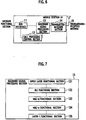
- FIG. 6 An example of general configuration of a mobile station UE is shown in FIG. 6 .
- the mobile station UE is provided with a bus interface 11, a call processing control section 12, a baseband signal processing section 13, a transmitter-receiver section 14, and a transmission- reception antenna 15.
- the mobile station UE can be configured to include an amplifier section (not shown in FIG. 4 ).
- these functions do not have to be independently present as hardware. That is, these functions can be partly or entirely integrated, or can be configured through a process of software.
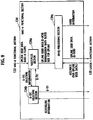
- FIG. 7 a functional block of the baseband signal processing section 13 is shown.
- the baseband signal processing section 13 is provided with an upper layer functional section 131, a RLC functional section 132, a MAC-d functional section 133, a MAC-e functional section 134, and a layer-1 functional section 135.
- the RLC functional section 132 is configured to work as a RLC sublayer.
- the layer-1 functional section 135 is configured to work as a layer-1.
- the RLC functional section 132 is configured to divide an application data (RLC SDU), which is received from the upper layer functional section 131, into PDUs of a predetermined PDU size. Then, the RLC functional section 132 is configured to generate RLC PDUs by adding a RLC header used for a sequence control processing, retransmission processing, and the like, so as to pass the RLC PDUs to the MAC-d functional section 133.
- RLC SDU application data
- the RLC functional section 132 is configured to generate RLC PDUs by adding a RLC header used for a sequence control processing, retransmission processing, and the like, so as to pass the RLC PDUs to the MAC-d functional section 133.
- a pipeline works as a bridge between the RLC functional section 132 and the MAC-d functional section 133 is a "logical channel".
- the logical channel is classified based on the contents of data to be transmitted/received, and when a communication is performed, it is possible to establish a plurality of logical channels in one connection. In other words, when the communication is performed, it is possible to transmit/receive a plurality of data with different contents (for example, control data and user data, or the like) logically in parallel.
- the MAC-d functional section 133 is configured to multiplex the logical channels, and to add a MAC-d header associated with the multiplex of the logical channels, so as to generate a MAC-d PDU.
- a plurality of MAC-d PDUs are transferred from the MAC-d functional section 133 to the MAC-e functional section 134 as MAC-d flow.
- the MAC-e functional section 134 is configured to assemble a plurality of MAC-d PDUs which are received from the MAC-d functional section 133 as MAC-d flow, and to add a MAC-e header to the assembled MAC-d PDU, so as to generate a transport block. Then, the MAC-e functional section 134 is configured to pass the generated transport block to the layer-1 functional section 135 through a transport channel.
- the MAC-e functional section 134 is configured to work as a lower layer of the MAC-d functional section 133, and to implement the retransmission control function according to Hybrid ARQ (HARQ) and the transmission rate control function.
- HARQ Hybrid ARQ
- the MAC-e functional section 134 is provided with a multiplex section 134a, an E-TFC selecting section 134b, and an HARQ processing section 134c.
- the multiplex section 134a is configured to perform a multiplex processing to the uplink user data, which is received from the MAC-d functional section 133 as MAC-d flow, based on a "Enhanced - Transport Format Indicator (E-TFI)" notified from the E-TFC selecting section 134b, so as to generate uplink user data (a Transport Block) to be transmitted via a transport channel (E-DCH). Then, the multiplex section 134a is configured to transmit the generated uplink user data (Transport Block) to the HARQ processing section 134c.
- E-TFI Enhanced - Transport Format Indicator
- uplink user data received as MAC-d flow is indicated as the “uplink user data (MAC-d flow)”
- uplink user data to be transmitted via the transport channel (E-DCH) is indicated as the “uplink user data (E-DCH)”.
- the E-TFI is an identifier of a transport format, which is a format for providing the transport block on the transport channel (E-DCH) per TTI, and the E-TFI is added to the MAC-e header.
- the multiplex section 134a is configured to determine a transmission data block size to be applied for the uplink user data based on the E-TFI notified from the E-TFC selecting section 134b, and to notify the determined transmission data block size to the HARQ processing section 134c.
- the multiplex section 134a when the multiplex section 134a receives the uplink user data from the MAC-d functional section 133 as MAC-d flow, the multiplex section 134a is configured to notify, to the E-TFC selecting section 134b, E-TFC selecting information for selecting a transport format for the received uplink user data.
- the E-TFC selecting information includes data size and priority class of the uplink user data, or the like.
- the HARQ processing section 134c is configured to perform the retransmission control processing for the "uplink user data (E-DCH)" according to the "N channel stop and wait (N-SAW) protocol” , based on ACK/NACK for the uplink user data notified from the layer-1 functional section 135.
- E-DCH uplink user data
- N-SAW N channel stop and wait
- the HARQ processing section 134c is configured to transmit, to the layer-1 functional section 135, the "uplink user data (E-DCH)" received from the multiplex section 134a, and HARQ information (for example, a number for retransmission, and the like) used for the HARQ processing.
- E-DCH uplink user data
- the E-TFC selecting section 134b is configured to determine the transmission rate of the uplink user data by selecting the transport format (E-TF) to be applied to the "uplink user data (E-DCH)".
- the E-TFC selecting section 134b is configured to determine whether the transmission of the uplink user data should be performed or stopped, based on scheduling information, the amount of data in MAC-d PDU, the condition of hardware resource of the radio base station Node B, and the like.
- the scheduling information (such as absolute transmission rate and a relative transmission rate of the uplink user data) is received from the radio base station Node B, the amount of data in MAC-d PDU (such as data size of the uplink user data) is passed from the MAC-d functional section 133, and the condition of hardware resource of the radio base station Node B is controlled in the MAC-e functional section 134.
- the E-TFC selection section 134b is configured to select the transport format (E-TF) to be applied to transmission of the uplink user data, and to notify the E-TFI for identifying the selected transport format to the layer-1 functional section 135 and the multiplex section 134a.
- E-TF transport format
- the E-TFC selecting section 134b is configured to store the transmission rate of uplink user data in association with the transport format, to update the transmission rate of uplink user data based on the scheduling information from the layer-1 functional section 135, and to notify, to the layer-1 functional section 135 and the multiplex section 134a, the E-TFI for identifying the transport format which is associated with the updated transmission rate of uplink user data.
- the E-TFC selecting section 134b when the E-TFC selecting section 134b receives the absolute transmission rate of the uplink user data from the serving cell for the mobile station UE via the E-AGCH as the scheduling information, the E-TFC selecting section 134b is configured to change the transmission rate of the uplink user data to the received absolute transmission rate of the uplink user data.
- the E-TFC selecting section 134b when the E-TFC selecting section 134b receives the relative transmission rate of the uplink user data (Down command or Don't care command) from the non-serving cell for the mobile station UE via the E-RGCH as the scheduling information, the E-TFC selecting section 134b is configured to increase/decrease the transmission rate of the uplink user data, at the timing of receiving the relative transmission rate, by the predetermined rate based on the relative transmission rate of the uplink user data.
- the transmission rate of the uplink user data can be a rate which can transmit an uplink user data via an "Enhanced Dedicated Physical Data Channel (E-DPDCH)", a transmission data block size (TBS) for transmitting an uplink user data, a transmission power of an "E-DPDCH”, or a transmission power ratio (a transmission power offset) between an "E-DPDCH” and a "Dedicated Physical Control Channel (DPCCH)".
- E-DPDCH Enhanced Dedicated Physical Data Channel
- TSS transmission data block size
- DPCCH Dedicated Physical Control Channel
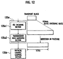
- the layer-1 functional section 135 is provided with a transmission channel encoding section 135a, a physical channel mapping section 135b, an E-DPDCH transmitting section 135c, an E-DPCCH transmitting section 135d, an E-HICH receiving section 135e, an E-RGCH receiving section 135f, an E-AGCH receiving section 135g, a physical channel de-mapping section 135j, a DPDCH transmitting section 135i, a DPCCH transmitting section (not shown), and a DPCH receiving section 135h.
- the transmission channel encoding section 135a is provided with a FEC (Forward Error Correction) encoding section 135a1, and a transmission rate matching section 135a2.
- FEC Forward Error Correction
- the FEC encoding section 135a1 is configured to perform the error correction encoding processing toward the "uplink user data (E-DCH)", that is, the transport block, transmitted from the MAC-e functional section 134.
- E-DCH uplink user data
- the transmission rate matching section 135a2 is configured to perform, toward the transport block to which the error correction encoding processing is performed, the processing of "repetition (repeat of bit)” and “puncture (bit skipping)” in order to match to the transmission capacity in the physical channel.
- the physical channel mapping section 135b is configured to pair the "uplink user data (E-DCH)" from the transmission channel encoding section 135a with the E-DPDCH, and to pair the E-TFI and the HARQ information from the transmission channel encoding section 135a with the E-DPCCH.
- E-DCH uplink user data
- the E-DPDCH transmitting section 135c is configured to perform a transmission processing of the E-DPDCH.
- the E-DPCCH transmitting section 135d is configured to perform a transmission processing of the E-DPCCH.
- the E-HICH receiving section 135e is configured to receive an "E-DCH HARQ Acknowledgement Indicator Channel (E-HICH)" transmitted from a cell (a serving cell or a non-serving cell for the mobile station UE).
- E-HICH E-DCH HARQ Acknowledgement Indicator Channel
- the E-RGCH receiving section 135f is configured to receive the E-RGCH transmitted from the cell (the serving cell and the non-serving cell for the mobile station UE).
- the E-AGCH receiving section 135g is configured to receive the E-AGCCH transmitted from the cell (the serving cell for the mobile station UE).
- the physical channel de-mapping section 135j is configured to extract the scheduling information (the relative transmission rate of the uplink user data, that is, UP command/ DOWN command) which is included in the E-RGCH received by the E-RGCH receiving section 135f, so as to transmit the extracted scheduling information to the MAC-e functional section 134.
- the scheduling information the relative transmission rate of the uplink user data, that is, UP command/ DOWN command
- the physical channel de-mapping section 135j is configured to extract the scheduling information (the absolute transmission rate of the uplink user data) which is included in the E-AGCH received by the E-AGCH receiving section 135g, so as to transmit the extracted scheduling information to the MAC-e functional section 134.
- the DPDCH transmitting section 135i is configured to perform a transmission processing of an uplink "Dedicated Physical Data Channel (DPDCH)" for transmitting uplink user data to be transmitted by the mobile station UE.
- DPDCH Dedicated Physical Data Channel
- the above uplink user data includes a measurement report, which reports transmission power of a common pilot channel transmitted from the cell.
- the DPCH receiving section 135h is configured to perform a receive processing of a downlink "Dedicated Physical Data Channel (DPCH)" transmitted from the cell.
- DPCH Dedicated Physical Data Channel
- the DPCH includes a "Dedicated Physical Data Channel (DPDCH)" and a “Dedicated Physical Control Channel (DPCCH)".
- DPDCH Dedicated Physical Data Channel
- DPCCH Dedicated Physical Control Channel
- FIG. 13 shows an example of a configuration of functional blocks of a radio base station Node B.
- the radio base station Node B is provided with an HWY interface 21, a baseband signal processing section 22, a transmitter-receiver section 23, an amplifier section 24, a transmission-reception antenna 25, and a call processing control section 26.
- the HWY interface 21 is configured to receive downlink user data to be transmitted from the radio network controller RNC, which is located in an upper level of the radio base station Node B, so as to enter the received downlink user data to the baseband signal processing section 22.
- the HWY interface 21 is configured to transmit uplink user data from the baseband signal processing section 22 to the radio network controller RNC.
- the baseband signal processing section 22 is configured perform the layer-1 processing such as channel encoding processing, spreading processing, and the like, to the downlink user data, so as to transmit the baseband signal including the downlink user data to the transmitter-receiver section 23.
- layer-1 processing such as channel encoding processing, spreading processing, and the like
- the baseband signal processing section 22 is configured to perform the layer-1 processing such as despreading processing, RAKE combining processing, error correction decoding processing, and the like, to the baseband signal, which is acquired from the transmitter-receiver section 23, so as to transmit the acquired uplink user data to the HWY interface 21.
- layer-1 processing such as despreading processing, RAKE combining processing, error correction decoding processing, and the like
- the transmitter-receiver section 23 is configured to convert the baseband signal, which is acquired from the baseband signal processing section 22, to radio frequency signals.
- the transmitter-receiver section 23 is configured to convert the radio frequency signals, which are acquired from the amplifier section 24, to the baseband signals.
- the amplifier section 24 is configured to amplify the radio frequency signals acquired from the transmitter-receiver section 23, so as to transmit the amplified radio frequency signals to the mobile station UE via the transmission-reception antenna 25.
- the amplifier section 24 is configured to amplify the signals received by the transmission-reception antenna 25, so as to transmit the amplified signals to the transmitter-receiver section 23.
- the call processing control section 26 is configured to transmit / receive the call processing control signals to / from the radio network controller RNC, and to perform the processing of condition control of each function in the radio base station Node B, allocating hardware resource in layer-3, and the like.
- FIG. 14 is a functional block diagram of the baseband signal processing section 22.
- the baseband signal processing section 22 is provided with a layer-1 functional section 221, and a MAC-e functional section 222.
- the layer-1 functional section 221 is provided with an E-DPCCH despreading-RAKE combining section 221a, an E-DPCCH decoding section 221b, an E-DPDCH despreading-RAKE combining section 221c, a buffer 221d, a re-despreading section 221e, an HARQ buffer 221f, an error correction decoding section 221g, a transmission channel encoding section 221h, a physical channel mapping section 221i, an E-HICH transmitting section 221j, an E-AGCH transmitting section 221k, an E-RGCH transmitting section 2211, a DPDCH respreading-RAKE combining section 221m, a DPDCH decoding section 221n, a DPCCH transmitting section (not shown), a DPCCH decoding section (not shown), and a DPCH transmitting section 221o.
- E-DPCCH despreading-RAKE combining section 221a an E-DPCCH decoding section
- these functions do not have to be independently present as hardware. That is, these functions can be partly or entirely integrated, or can be configured through a process of software.
- the E-DPCCH despreading-RAKE combining section 221a is configured to perform the despreading processing and RAKE combining processing to the E-DPCCH.
- the E-DPCCH decoding section 221b is configured to decode the E-TFCI for determining the transmission rate of the uplink user data (or an "Enhanced Transport Format and Resource Indicator (E-TFRI)" based on the output from the E-DPCCH despreading-RAKE combining section 221a, so as to transmit the decoded E-TFCI to the MAC-e functional section 222.
- E-TFRI Enhanced Transport Format and Resource Indicator
- the E-DPDCH despreading-RAKE combining section 221c is configured to perform the despreading processing to the E-DPDCH using the spreading factor (the minimum spreading factor) and the number of multi-codes which correspond to the maximum rate that the E-DPDCH can use, so as to store the despread data to the buffer 221d.
- the radio base station Node B By performing the despreading processing using the above described spreading factor and the number of multi-codes, it is possible for the radio base station Node B to reserve the resources so that the radio base station Node B can receive the uplink data up to the maximum rate (bit rate) that the mobile station UE can use.
- the re-despreading section 221e is configured to perform the re-despreading processing to the data stored in the buffer 221d using the spreading factor and the number of multi-codes which are notified from the MAC-e functional section 222, so as to store the re-despread data to the HARQ buffer 221f.
- the error correction decoding section 221g is configured to perform the error correction decoding processing to the data stored in the HARQ buffer 221f based on the coding rate which is notified from the MAC-e functional section 222, so as to transmit the acquired "uplink user data (E-DCH)" to the MAC-e functional section 222.
- E-DCH uplink user data
- the transmission channel encoding section 221h is configured to perform the necessary encoding processing to the ACK/NACK and the scheduling information for the uplink user data received from the MAC-e functional section 222.
- the physical channel mapping section 221i is configured to pair the ACK/NACK for the uplink user data, which is acquired from the transmission channel encoding section 221h, with the E-HICH, to pair the scheduling information (absolute transmission rate), which is acquired from the transmission channel encoding section 221h, with the E-AGCH, and to pair the scheduling information (relative transmission rate), which is acquired from the transmission channel encoding section 221h, with the E-RGCH.
- the E-HICH transmitting section 221j is configured to perform a transmission processing of the E-HICH.
- the E-AGCH transmitting section 221k is configured to perform a transmission processing of the E-AGCH.
- the E-AGCH transmitting section 221k is configured to determine the transmission power of the E-AGCH based on the first E-AGCH offset or the second E-AGCH offset, which are notified from the scheduling section 222c, and the transmission power of the downlink DPCH, and to transmit the E-AGCH using the determined transmission power.
- the E-AGCH transmitting section 221k is configured to acquire the transmission power of the downlink DPCH from the DPCH transmitting section 221o, and to multiply or add the first E-AGCH offset or the second E-AGCH offset, which is notified from the scheduling section 222c, to the transmission power of the downlink DPCH, so as to determine the transmission power of the E-AGCH.
- the E-RGCH transmitting section 2211 is configured to perform a transmission processing to the E-RGCH.
- the DPDCH despreading-RAKE combining section 221m is configured to perform the despreading processing and the RAKE combining processing to the DPDCH.
- the DPDCH decoding section 221n is configured to decode the uplink user data transmitted from the mobile station UE, based on the output from the DPDCH despreading-RAKE combining section 221m, so as to transmit the decoded uplink user data to the MAC-e functional section 222.
- the above uplink user data includes a measurement report, which reports reception power of a common pilot channel transmitted from the mobile station UE.
- the DPCH transmitting section 221o is configured to perform a transmission processing to a "Dedicated Physical Channel (DPCH)" for downlink transmitted from the radio base station Node B.
- DPCH Dedicated Physical Channel
- the DPCH transmitting section 221o is configured to notify the transmission power of the downlink DPCH to the E-AGCH transmitting section 221k.
- the MAC-e functional section 222 is provided with an HARQ processing section 222a, a receive processing command section 222b, a scheduling section 222c, and a de-multiplex section 222d.
- the HARQ processing section 222a is configured to receive the uplink user data and the HARQ information which are received from the layer-1 functional section 221, so as to perform the HARQ processing on the "uplink user data (E-DCH)".
- the HARQ processing section 222a is configured to notify, to the layer-1 functional section 221, the ACK/NACK (for the uplink user data) which shows the result of receive processing on the "uplink user data (E-DCH)".
- the HARQ processing section 222a is configured to notify, to the scheduling section 222c, the ACK/NACK (for the uplink user data) per process.
- the receive processing command section 222b is configured to notify, to the re-despreading section 221e and the HARQ buffer 221f, the spreading factor and the number of multi-codes for the transport format of each mobile station UE, which is specified by the E-TFCI per TTI received from the E-DPCCH decoding section 221b in the layer-1 functional section 221. Then, the receive processing command section 222b is configured to notify the encoding rate to the error correction decoding section 221g.
- the scheduling section 222c is configured to change the absolute transmission rate or the relative transmission rate of the uplink user data, based on the E-TFCI per TTI received from the E-DPCCH decoding section 221 in the layer-1 functional section 221, the ACK/NACK per process received from the HARQ processing section 222a, the interference level, and the like.
- the scheduling section 222c is configured to notify, to the layer-1 functional section 221, the absolute transmission rate or the relative transmission rate of the uplink user data, as the scheduling information.
- the scheduling section 222c is configured to receive E-AGCH offset information which is transmitted from the radio network controller RNC via the HWY interface.
- the scheduling section 222c is configured to notify the first E-AGCH offset or the second E-AGCH offset, which is included in the E-AGCH offset information, to the layer-1 functional section 221.
- the de-multiplex section 222d is configured to perform the de-multiplex processing to the "uplink user data (E-DCH and DCH)" received from the HARQ processing section 222a, so as to transmit the acquired uplink user data to the HWY interface 21.
- the above uplink user data includes a measurement report, which reports reception power of a common pilot channel transmitted from the mobile station UE.
- the radio network controller RNC is an apparatus located in an upper level of the radio base station Node B, and is configured to control radio communications between the radio base station Node B and the mobile station UE.
- the radio network controller RNC is provided with an exchange interface 31, a Logical Link Control (LLC) layer functional section 32, a MAC layer functional section 33, a media signal processing section 34, a radio base station interface 35, and a call processing control section 36.
- LLC Logical Link Control
- the exchange interface 31 is an interface with an exchange 1, and is configured to forward the downlink signals transmitted from the exchange 1 to the LLC layer functional section 32, and to forward the uplink signals transmitted from the LLC layer functional section 32 to the exchange 1.
- the LLC layer functional section 32 is configured to perform an LLC sub-layer processing such as a combining processing of a header or a trailer such as a sequence pattern number.
- the LLC layer functional section 32 is also configured to transmit the uplink signals to the exchange interface 31 and to transmit the downlink signals to the MAC layer functional section 33, after the LLC sub-layer processing is performed.
- the MAC layer functional section 33 is configured to perform a MAC layer processing such as a priority control processing or a header adding processing.
- the MAC layer functional section 33 is also configured to transmit the uplink signals to the LLC layer functional section 32 and to transmit the downlink signals to the radio base station interface 35 (or the media signal processing section 34), after the MAC layer processing is performed.
- the media signal processing section 34 is configured to perform a media signal processing against voice signals or real time image signals.
- the media signal processing section 34 is also configured to transmit the uplink signals to the MAC layer functional section 33 and to transmit the downlink signals to the radio base station interface 35, after the media signal processing is performed.
- the radio base station interface 35 is an interface with the radio base station Node B.
- the radio base station interface 35 is configured to forward the uplink signals transmitted from the radio base station Node B to the MAC layer functional section 33 (or the media signal processing section 34) and to forward the downlink signals transmitted from the MAC layer functional section 33 (or the media signal processing section 34) to the radio base station Node B.
- the call processing control section 36 is configured to perform a radio resource control processing, a channel setup and release processing by the layer-3 signaling, or the like.
- the radio resource control includes call admission control, handover control, or the like.
- the call processing control section 36 is configured to notify the E-AGCH offset information to the radio base station Node B via the radio base station interface 35.
- the call control section 36 is configured to store a transmission power ratio between the E-AGCH and the DPCH, as the first E-AGCH offset 37 or the second E-AGCH offset 37.
- the call processing control section 36 is configured to generate the E-AGCH offset information which includes the second E-AGCH offset, when the mobile station UE is performing the SHO, by establishing the radio links with a plurality of cells.
- the call processing control section 36 is configured to generate the E-AGCH offset information which includes the first E-AGCH offset, when the mobile station UE is not performing the SHO, and is establishing the radio link with one cell.
- the radio links includes the DPCH or the E-DPDCH between the mobile station UE and the radio base station Node B.
- the state in which the mobile station UE is establishing the radio link with one cell is indicated as "a Non-SHO state”
- the state in which the mobile station UE is establishing the radio links with a plurality of cells is indicated as "a SHO state”.
- Each of the first E-AGCH offset and the second E-AGCH offset is the transmission power ratio between the E-AGCH and the DPCH, and it is configured that the second E-AGCH offset should be greater than the first E-AGCH offset.
- E-AGCH absolute transmission rate control channel
- a radio base station Node B is configured to control one or a plurality of cells
- the cells include the functions of the radio base station Node B will be described.
- the cell #10 is a serving cell for the mobile station UE
- the cell #20 is a non-serving cell for the mobile station UE. Accordingly, the mobile station UE is configured to control the transmission rate of the uplink user data, based on the E-AGCH transmitted from the serving cell #10.
- both of cell #10 and cell #20 are controlled by a same single radio base station Node B, or the each of cell #10 and cell #20 is controlled by different radio base stations Node B.
- step S1001 the mobile station UE is establishing a data connection for transmitting uplink user data with the radio network controller RNC via the cell #10.
- the cell #10 is configured to determine the transmission power of the E-AGCH, based on the transmission power of the downlink DPCH and the first E-AGCH offset.
- the cell #10 is configured to multiply or add the first E-AGCH offset which is included in the E-AGCH offset information transmitted from the radio network controller RNC in advance, to the downlink DPCH to which the closed loop transmission power control is performed, so as to determine the transmission power of the E-AGCH.
- step S1002 when the reception power of the common pilot signal from the cell #20 become more than or equal to the predetermined value, the mobile station UE transmits a measurement report to the radio network controller RNC.
- step S1003 the radio network controller RNC requests the radio base station Node B #2 which controls the cell #20 to establish synchronization of radio links for uplink between the mobile station UE and the cell #20, based on the transmitted measurement report.
- the radio network controller RNC transmits a SHO setting request to the radio base station Node #2 which controls the cell #20, so as to request to establish synchronization of the radio links for uplink between the mobile station UE and the cell #20.
- the SHO setting request includes a channelization code for identifying the channel configuration in the radio link, and a scrambling code for identifying the mobile station UE.
- step S1004 the radio base station Node B #2 which controls the cell #20 establishes the synchronization of the radio links for uplink between the mobile station UE and the cell #20.
- the radio base station Node B #2 which controls the cell #20 detects the channel transmitted by the mobile station UE using the channelization code and the scrambling code received from the radio network controller RNC, so as to establish the synchronization of the radio links for uplink between the mobile station UE and the cell #20.
- the radio base station Node B #2 which controls the cell #20 transmits a SHO setting response to the radio network controller RNC.
- the cell #20 starts the transmission of the DPCH and the like to the mobile station UE.
- step S1005 the radio network controller RNC requests the mobile station UE to establish synchronization of radio links for downlink between the cell #20 and the mobile station UE.
- the radio network controller RNC transmits a SHO setting request to the mobile station UE, so as to request to establish the synchronization of radio links or downlink between the cell #20 and the mobile station UE.
- the SHO setting request includes a channelization code for identifying the channel configuration in the radio link for downlink, and a scrambling code for identifying the cell #20.
- step S1006 the mobile station UE establishes the synchronization of radio links for downlink between the cell #20 and the mobile station UE.
- the mobile station UE detects the channel transmitted from the cell #20 using the channelization code and the scrambling code received from the radio network controller RNC, so as to establish the synchronization of the radio links for downlink between the cell #20 and the mobile station UE.
- the mobile station UE When the synchronization of the radio links for downlink between the cell #20 and the mobile station UE is established, the mobile station UE transmits a SHO setting response to the radio network controller RNC.
- step S1007 the radio network controller RNC transmits the E-AGCH offset information including the second E-AGCH offset, to the radio base station Node B #1 which controls the cell #10 (the serving cell for the mobile station UE).
- the E-AGCH offset information may be transmitted to the radio base station Node B, by the SHO setting request.
- step S1008 the cell #10 determines the transmission power of the E-AGCH, based on the second E-AGCH offset which is included in the E-AGCH offset information transmitted from the radio network controller RNC.
- the second E-AGCH offset transmitted from the radio network controller RNC is set to be greater than the first E-AGCH offset.
- the cell #10 sets the E-AGCH offset greater, and to increase the transmission power of the E-AGCH, so as to ensure the transmission of the E-AGCH to the mobile station UE which is performing the SHO.
- step S2001 when the reception power of the common pilot signal from the cell #20 become less than the predetermined value, the mobile station UE transmits a measurement report to the radio network controller RNC.
- step S2002 the radio network controller RNC requests the radio base station Node B #2 which controls the cell #20 to release the radio links for uplink between the mobile station UE and the cell #20, based on the transmitted measurement report.
- the radio network controller RNC transmits a SHO release request to the mobile station UE, so as to release the radio link for downlink between the cell #20 and the mobile station UE.
- step S2003 the radio network controller RNC transmits the E-AGCH offset information including the first E-AGCH offset to the radio base station Node B #1.
- step S2004 the cell #10, which has received the E-AGCH offset information, determines the transmission power of the E-AGCH, based on the first E-AGCH offset included in the E-AGCH offset information and the transmission power of the downlink DPCH.
- the cell #10 is configured to minimize the E-AGCH offset in the Non-SHO state appropriately, and to adjust the transmission power of the E-AGCH, so as to use the radio network capacity effectively.
- the radio network controller RNC transmits the E-AGCH offset information including the second E-AGCH offset, when the mobile station UE is performing the SHO, is shown.
- the radio network controller RNC can be configured to transmit the E-AGCH offset information including the second E-AGCH offset based on the predetermined notification from the mobile station UE and the cell (for example, a predetermined measurement report from the mobile station UE, and the like).
- the transmission power control method and the mobile communication system it is possible to transmit the E-AGCH to the mobile station UE, even when the mobile station UE is performing the SHO.
- the cell or the radio base station Node B which controls the cell can set the E-AGCH offset greater, and increase the transmission power of the E-AGCH greater. Therefore, it is possible to ensure the transmission of the E-AGCH to the mobile station UE.
Abstract
Description
- The present invention relates to a transmission power control method and a mobile communication system for controlling a transmission power of an absolute transmission rate control channel including an absolute transmission rate of uplink user data, which is transmitted from a cell controlled by a radio base station to a mobile station.
- In a conventional mobile communication system, when setting a Dedicated Physical Channel (DPCH) between a mobile station UE and a radio base station Node B, a radio network controller RNC is configured to determine a transmission rate of uplink user data, in consideration of hardware resources for receiving of the radio base station Node B (hereinafter, hardware resource), a radio resource in an uplink (an interference volume in an uplink), a transmission power of the mobile station UE, a transmission processing performance of the mobile station UE, a transmission rate required for an upper application, or the like, and to notify the determined transmission rate of the uplink user data by a message of a layer-3 (Radio Resource Control Layer) to both of the mobile station UE and the radio base station Node B.
- Here, the radio network controller RNC is provided at an upper level of the radio base station Node B, and is an apparatus configured to control the radio base station Node B and the mobile station UE.
- In general, data communications often cause burst traffic compared with voice communications or TV communications. Therefore, it is preferable that a transmission rate of a channel used for the data communications is changed fast.
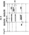
- However, as shown in
FIG. 1 , the radio network controller RNC integrally controls a plurality of radio base stations Node B in general. Therefore, in the conventional mobile communication system, there has been a problem that it is difficult to perform fast control for changing of the transmission rate of uplink user data (for example, per approximately 1 through 100 ms), due to the increase of processing load and processing delay in the radio network controller RNC. - In addition, in the conventional mobile communication system, there has been also a problem that costs for implementing an apparatus and for operating a network are substantially increased even if the fast control for changing of the transmission rate of the uplink user data can be performed.
- Therefore, in the conventional mobile communication system, control for changing of the transmission rate of the uplink user data is generally performed on the order from a few hundred ms to a few seconds.
- Accordingly, in the conventional mobile communication system, when burst data transmission is performed as shown in
FIG. 2A , the data are transmitted by accepting low-speed, high-delay, and low-transmission efficiency as shown inFIG. 2B , or, as shown inFIG. 2C , by reserving radio resources for high-speed communications to accept that radio bandwidth resources in an unoccupied state and hardware resources in the radio base station Node B are wasted. - It should be noted that both of the above-described radio bandwidth resources and hardware resources are applied to the vertical radio resources in
FIGS. 2B and 2C . - Therefore, the 3rd Generation Partnership Project (3GPP) and the 3rd Generation Partnership Project 2 (3GPP2), which are international standardization organizations of the third generation mobile communication system, have discussed a method for controlling radio resources at high speed in a layer-1 and a media access control (MAC) sub-layer (a layer-2) between the radio base station Node B and the mobile station UE, so as to utilize the uplink radio resources effectively. Such discussions or discussed functions will be hereinafter referred to as "Enhanced Uplink (EUL)".
- Referring to
FIG. 3 , the mobile communication system, to which the "Enhanced Uplink" is applied, is explained. - As shown in an example of
FIG. 3 , thecell # 2 which is controlled by the radio base stationNode B # 1 is a serving cell for controlling the transmission rate of uplink user data of the mobile station UE mainly, and thecell # 2 is configured to transmit an "Enhanced Absolute Grant Channel (E-AGCH)" which notifies an absolute transmission rate of the uplink user data, to the mobile station UE. - In addition, the above mobile communication system is configured to control the transmission rate of the uplink user data transmitted via an "Enhanced Dedicated Physical Channel (E-DPDCH)" based on the transmission rate control using the above described E-AGCH.
- Further, in the above mobile communication system, a closed loop transmission power control using a "Transmit Power Control (TPC) command" is known, as an example of the transmission power control method for a downlink dedicated physical channel (herein after, DPCH) transmitted from the radio base station Node B.
- Referring to
FIG. 4A , the closed loop transmission power control using the TPC command is described. - As shown in
FIG. 4A , the mobile station UE, which has received a downlink DPCH transmitted from thecell # 2, is configured to determine the increase/decrease of a transmission power of the downlink DPCH in thecell # 2 controlled by the radio base station Node B, based on the transmission power of the received downlink DPCH. Then, the mobile station UE is configured to transmit the determined result of the increase/decrease of the transmission power of the downlink DPCH to thecell # 2, using the TPC command (for example, UP command/Down Command) . - In addition, the
cell # 2 is configured to control the transmission power of the downlink DPCH to be transmitted to the mobile station UE, using the TPC command transmitted from the mobile station UE. - In the example of
FIG. 4A , thecell # 2 is a serving cell for controlling the transmission rate of the uplink user data transmitted from the mobile station UE mainly, and thecell # 2 is configured to transmit the E-AGCH to the mobile station UE. - In addition, in the above mobile communication system, the
cell # 2 which is a serving cell for the mobile station UE is configured to determine the transmission power of the E-AGCH, based on the transmission power of the downlink DPCH and a predetermined offset (an E-AGCH offset). - As described above, in the mobile communication system, the reception power of the downlink DPCH in the mobile station UE will be improved by the transmission power control using the TPC command, and therefore, the reception power of the E-AGCH, which depends on the downlink DPCH, will be also improved.
- Next, referring to
FIG. 4B , the transmission power control using the TPC command in the mobile communication system in which soft-handover (SHO) is performed is described. - In the above mobile communication system, as shown in
FIG. 4B , when the mobile station UE is performing the SHO by establishing radio links with thecell # 3 as well as thecell # 4, and when the mobile station UE receives thesame DPCHs # 1 transmitted from thecell # 3 and thecell # 4, the mobile station UE is configured to combine theDPCH # 1 received from thecell # 3 and theDPCH# 1 received from thecell # 4, so as to determine the increase/decrease of the transmission power of theDPCH # 1 in both of thecell # 3 and thecell # 4, based on the reception power of the combinedDPCH # 1. - Then, the mobile station UE is configured to transmit the determined result of the increase/decrease of the transmission power of the
DPCH # 1 to the both of thecell # 3 and thecell # 4, using the TPC command. - Here, in the example of
FIG. 4B , thecell # 3 is a serving cell for the mobile station UE, and thecell # 4 is a non-serving cell for the mobile station UE, which is a cell other than the serving cell and establishes a radio link with the mobile station UE. Accordingly, the mobile station UE is configured to receive theE-AGCH # 1 which is transmitted from the servingcell # 3. - In addition, in the above mobile communication system, the transmission power of the
E-AGCH # 1 transmitted from thecell # 3 is configured to be determined, based on the transmission power of theDPCH # 1 transmitted from thecell # 3 and the predetermined offset (the E-AGCH offset). - Further, as shown in
FIG. 4B , in the above mobile communication system, if the mobile station UE is performing the SHO by establishing the radio links with thecell # 3 as well as thecell # 4, and if the reception power of theDPCH # 1 transmitted from thecell # 3 is good enough, even when the reception power of theDPCH # 1 transmitted from thecell # 4 is insufficient, the reception power of the combinedDPCH # 1 will be sufficient for the mobile station UE. - Therefore, in the above mobile communication system, the mobile station UE can receive the
DPCH # 1, if the reception power of theDPCH # 1 transmitted from thecell # 3 is good enough, even when the reception power of theDPCH # 1 transmitted from thecell # 4 is insufficient. - Accordingly, in such a condition, the transmission power of the
DPCH # 1 does not have to be increased, and the mobile station UE is configured not to transmit the TPC command (for example, UP command) for increasing the transmission power of theDPCH # 1 transmitted from thecell # 4. - However, when the environment around the mobile station UE is changed in accordance with the moving of the mobile station UE, and the like, when the transmission power of the
DPCH # 1 transmitted from the servingcell # 3 decreases, and when the transmission power of theDPCH # 1 transmitted from thenon-serving cell # 4 increases, the mobile station UE does not have to increase the transmission power of theDPCH # 1, as the transmission power of theDPCH # 1 transmitted from thecell # 4 is good enough. - Accordingly, the mobile station UE is not configured to transmit the TPC command (for example, UP command) for increasing the transmission power of the
DPCH # 1 transmitted from thecell # 3, so that the reception power of theDPCH # 1 transmitted from theserving cell # 3 cannot be improved. - Here, the transmission power of the
E-AGCH # 1 transmitted from thecell # 3 is determined, based on the transmission power of theDPCH # 1 transmitted from thecell # 3, and the predetermined offset (for example, by multiplying or adding the E-AGCH offset to the DPCH, and the like). - Accordingly, as shown in
FIG. 5 , the mobile station UE may not receive theE-AGCH # 1, because the reception power of theE-AGCH # 1 transmitted from thecell # 3 is insufficient. - Therefore, there has been a problem that, when the SHO is performing in the mobile communication system , as shown in
FIG. 5 , the mobile station UE cannot control the transmission rate of the uplink user data of the mobile station UE (such as E-DPDCH #1) based on the E-AGCH transmitted from theserving cell # 3. - The prior art, under the European Patent Convention, also includes the following documents.
- "Universal Mobile Telecommunications System (UMTS); Physical layer procedures (FDD)" (3GPP TS 25.214 version 6.5.0 Release 6), ETSI TS 125 214 V6.5.0 (2005-03), discloses characteristics of physical layer procedures in the FDD (frequency division duplex) mode of UTRA (UMTS terrestrial radio access). The E-AGCH (Enhanced dedicated channel (E-DCH) absolute grant channel) power control is under control of the node B.
- Parkvall S. et al., "WCDMA Enhanced Uplink - Principles and Basic Operation", Vehicular Technology Conference, 2005 discloses some principles and features of the fast scheduling framework in the WCDMA enhanced uplink. The scheduling framework is based on scheduling grants sent by the node B scheduler to control the user equipment (UE) transmission activity and scheduling requests are sent by the user equipment to request resources. Two types of grants are used: absolute grants and relative grants.
- International application
WO 03/017525 A1 - The present invention has been made considering the problems, and its object is to provide a transmission power control method and a mobile communication system, in which E-AGCH can be certainly reached to a mobile station UE, even when the mobile station UE is performing the soft-handover.
- The invention is defined in the claims.
- According to an aspect, the transmission power control method is further a method for controlling a transmission power of an absolute transmission rate control channel including an absolute transmission rate of uplink user data, which is transmitted from a cell controlled by a radio base station to a mobile station, including: notifying, from a radio network controller to the radio base station which controls a serving cell, an offset between the transmission power of the absolute transmission rate control channel and a transmission power of a dedicated physical channel, when the mobile station is performing a soft-handover with the serving cell and non-serving cells; determining, at the serving cell to which the offset is notified, the transmission power of the absolute transmission rate control channel based on the notified offset; and transmitting, at the serving cell, the absolute transmission rate control channel to the mobile station using the determined transmission power.
- In the first aspect, the radio network controller can be configured to notify, to the radio base station which Controls the serving cell, the offset between the transmission power of the absolute transmission rate control channel and the transmission power of the dedicated physical channel, when the mobile station is not performing the soft-handover with the serving cell and non-serving cells.
- According to an aspect, the mobile communication system is further a system for controlling a transmission power of an absolute transmission rate control channel including an absolute transmission rate of uplink user data, which is transmitted from a cell controlled by a radio base station to a mobile station, wherein a radio network controller is configured to notify, to the radio base station which controls a serving cell, an offset between the transmission power of the absolute transmission rate control Channel and a transmission power of a dedicated physical channel, when the mobile station is performing a soft-handover with the serving cell and non-serving cells, and the serving cell is configured to determine the transmission power of the absolute transmission rate control channel based on the notified offset, and to transmit the absolute transmission rate control channel to the mobile station using the determined transmission power.
-
-
FIG. 1 is diagram of an entire configuration of a general mobile communication system. -
FIGs. 2A to 2C are diagrams for explaining a method for controlling a transmission power in a conventional mobile communication system. -
FIG. 3 is a diagram of an entire configuration of the conventional mobile communication system. -
FIGs. 4A and 4B are diagrams for explaining a transmission power control method in the conventional mobile communication system. -
FIG. 5 is a diagram for explaining the transmission power control method in the conventional mobile communication system. -
FIG. 6 is a functional block diagram of a mobile station in the mobile communication system. -
FIG. 7 is a functional block diagram of a baseband signal processing section of the mobile station in the mobile communication system. -
FIG. 8 is a diagram for explaining functions of the baseband signal processing section of the mobile station in the mobile communication system. -
FIG. 9 is a functional block diagram of a MAC-e functional section in the baseband signal processing section of the mobile station in the mobile communication system. -
FIG. 10 is a graph illustrating an operation of four channel stop and wait protocol performed by an HARQ processing section in the MAC-e finctional section in the baseband signal processing section of the mobile station in the mobile communication system. -
FIG. 11 is a functional block diagram of a layer-1 functional section in the baseband signal processing section of the mobile station in the mobile communication system. -
FIG. 12 is a diagram for explaining functions of the layer-1 functional section in the baseband signal processing section of the mobile station in the mobile communication system. -
FIG. 13 is a functional block diagram of a radio base station. -
FIG. 14 is a functional block diagram of a baseband signal processing section in the radio base station of the mobile communication system. -
FIG. 15 is a functional block diagram of a layer-1 functional section in the baseband signal processing section in the radio base station of the mobile communication system. -
FIG. 16 is a functional block diagram of a MAC-e functional section in the baseband signal processing section in the radio base station of the communication system. -
FIG. 17 is a functional block diagram of a radio network controller of the mobile communication system. -
FIG. 18 is a sequence diagram showing an example of a transmission power control method according to the first embodiment of the present invention. -
FIG. 19 is a sequence diagram showing an example of the transmission power control method. - Referring to
FIGs. 6 to 17 , a configuration of a mobile communication system will be described. - It should be noted that, the mobile communication system is designed in order to increase a communication performance such as a communication capacity, a communication quality and the like. Further, the mobile communication system can be applied to "W-CDMA" and "CDMA2000" of the third generation mobile communication system.
- An example of general configuration of a mobile station UE is shown in
FIG. 6 . - As shown in
FIG. 6 , the mobile station UE is provided with abus interface 11, a call processing control section 12, a basebandsignal processing section 13, a transmitter-receiver section 14, and a transmission-reception antenna 15. In addition, the mobile station UE can be configured to include an amplifier section (not shown inFIG. 4 ). - However, these functions do not have to be independently present as hardware. That is, these functions can be partly or entirely integrated, or can be configured through a process of software.
- In
FIG. 7 , a functional block of the basebandsignal processing section 13 is shown. - As shown in
FIG. 7 , the basebandsignal processing section 13 is provided with an upper layerfunctional section 131, a RLCfunctional section 132, a MAC-dfunctional section 133, a MAC-efunctional section 134, and a layer-1functional section 135. - The RLC
functional section 132 is configured to work as a RLC sublayer. The layer-1functional section 135 is configured to work as a layer-1. - As shown in
FIG. 8 , the RLCfunctional section 132 is configured to divide an application data (RLC SDU), which is received from the upper layerfunctional section 131, into PDUs of a predetermined PDU size. Then, the RLCfunctional section 132 is configured to generate RLC PDUs by adding a RLC header used for a sequence control processing, retransmission processing, and the like, so as to pass the RLC PDUs to the MAC-dfunctional section 133. - Here, a pipeline works as a bridge between the RLC
functional section 132 and the MAC-dfunctional section 133 is a "logical channel". The logical channel is classified based on the contents of data to be transmitted/received, and when a communication is performed, it is possible to establish a plurality of logical channels in one connection. In other words, when the communication is performed, it is possible to transmit/receive a plurality of data with different contents (for example, control data and user data, or the like) logically in parallel. - The MAC-d
functional section 133 is configured to multiplex the logical channels, and to add a MAC-d header associated with the multiplex of the logical channels, so as to generate a MAC-d PDU. A plurality of MAC-d PDUs are transferred from the MAC-dfunctional section 133 to the MAC-efunctional section 134 as MAC-d flow. - The MAC-e
functional section 134 is configured to assemble a plurality of MAC-d PDUs which are received from the MAC-dfunctional section 133 as MAC-d flow, and to add a MAC-e header to the assembled MAC-d PDU, so as to generate a transport block. Then, the MAC-efunctional section 134 is configured to pass the generated transport block to the layer-1functional section 135 through a transport channel. - In addition, the MAC-e
functional section 134 is configured to work as a lower layer of the MAC-dfunctional section 133, and to implement the retransmission control function according to Hybrid ARQ (HARQ) and the transmission rate control function. - Specifically, as shown in
FIG. 9 , the MAC-efunctional section 134 is provided with amultiplex section 134a, an E-TFC selectingsection 134b, and anHARQ processing section 134c. - The
multiplex section 134a is configured to perform a multiplex processing to the uplink user data, which is received from the MAC-dfunctional section 133 as MAC-d flow, based on a "Enhanced - Transport Format Indicator (E-TFI)" notified from the E-TFC selectingsection 134b, so as to generate uplink user data (a Transport Block) to be transmitted via a transport channel (E-DCH). Then, themultiplex section 134a is configured to transmit the generated uplink user data (Transport Block) to theHARQ processing section 134c. - Hereinafter, the uplink user data received as MAC-d flow is indicated as the "uplink user data (MAC-d flow)", and the uplink user data to be transmitted via the transport channel (E-DCH) is indicated as the "uplink user data (E-DCH)".
- The E-TFI is an identifier of a transport format, which is a format for providing the transport block on the transport channel (E-DCH) per TTI, and the E-TFI is added to the MAC-e header.
- The
multiplex section 134a is configured to determine a transmission data block size to be applied for the uplink user data based on the E-TFI notified from the E-TFC selectingsection 134b, and to notify the determined transmission data block size to theHARQ processing section 134c. - In addition, when the
multiplex section 134a receives the uplink user data from the MAC-dfunctional section 133 as MAC-d flow, themultiplex section 134a is configured to notify, to theE-TFC selecting section 134b, E-TFC selecting information for selecting a transport format for the received uplink user data. - Here, the E-TFC selecting information includes data size and priority class of the uplink user data, or the like.
- The
HARQ processing section 134c is configured to perform the retransmission control processing for the "uplink user data (E-DCH)" according to the "N channel stop and wait (N-SAW) protocol" , based on ACK/NACK for the uplink user data notified from the layer-1functional section 135. An example for operations of the "4 channel stop and wait protocol" is shown inFIG. 10 . - In addition, the
HARQ processing section 134c is configured to transmit, to the layer-1functional section 135, the "uplink user data (E-DCH)" received from themultiplex section 134a, and HARQ information (for example, a number for retransmission, and the like) used for the HARQ processing. - The
E-TFC selecting section 134b is configured to determine the transmission rate of the uplink user data by selecting the transport format (E-TF) to be applied to the "uplink user data (E-DCH)". - Specifically, the E-TFC selecting
section 134b is configured to determine whether the transmission of the uplink user data should be performed or stopped, based on scheduling information, the amount of data in MAC-d PDU, the condition of hardware resource of the radio base station Node B, and the like. - The scheduling information (such as absolute transmission rate and a relative transmission rate of the uplink user data) is received from the radio base station Node B, the amount of data in MAC-d PDU (such as data size of the uplink user data) is passed from the MAC-d
functional section 133, and the condition of hardware resource of the radio base station Node B is controlled in the MAC-efunctional section 134. - Then, the
E-TFC selection section 134b is configured to select the transport format (E-TF) to be applied to transmission of the uplink user data, and to notify the E-TFI for identifying the selected transport format to the layer-1functional section 135 and themultiplex section 134a. - For example, the E-TFC selecting
section 134b is configured to store the transmission rate of uplink user data in association with the transport format, to update the transmission rate of uplink user data based on the scheduling information from the layer-1functional section 135, and to notify, to the layer-1functional section 135 and themultiplex section 134a, the E-TFI for identifying the transport format which is associated with the updated transmission rate of uplink user data. - Here, when the
E-TFC selecting section 134b receives the absolute transmission rate of the uplink user data from the serving cell for the mobile station UE via the E-AGCH as the scheduling information, the E-TFC selectingsection 134b is configured to change the transmission rate of the uplink user data to the received absolute transmission rate of the uplink user data. - In addition, when the
E-TFC selecting section 134b receives the relative transmission rate of the uplink user data (Down command or Don't care command) from the non-serving cell for the mobile station UE via the E-RGCH as the scheduling information, the E-TFC selectingsection 134b is configured to increase/decrease the transmission rate of the uplink user data, at the timing of receiving the relative transmission rate, by the predetermined rate based on the relative transmission rate of the uplink user data. - In this specification, the transmission rate of the uplink user data can be a rate which can transmit an uplink user data via an "Enhanced Dedicated Physical Data Channel (E-DPDCH)", a transmission data block size (TBS) for transmitting an uplink user data, a transmission power of an "E-DPDCH", or a transmission power ratio (a transmission power offset) between an "E-DPDCH" and a "Dedicated Physical Control Channel (DPCCH)".
- As shown in
FIG. 11 , the layer-1functional section 135 is provided with a transmissionchannel encoding section 135a, a physicalchannel mapping section 135b, anE-DPDCH transmitting section 135c, anE-DPCCH transmitting section 135d, an E-HICH receiving section 135e, an E-RGCH receiving section 135f, an E-AGCH receiving section 135g, a physical channel de-mapping section 135j, aDPDCH transmitting section 135i, a DPCCH transmitting section (not shown), and aDPCH receiving section 135h. - As shown in
FIG. 12 , the transmissionchannel encoding section 135a is provided with a FEC (Forward Error Correction) encoding section 135a1, and a transmission rate matching section 135a2. - As shown in
FIG. 12 , the FEC encoding section 135a1 is configured to perform the error correction encoding processing toward the "uplink user data (E-DCH)", that is, the transport block, transmitted from the MAC-efunctional section 134. - In addition, as shown in
FIG. 12 , the transmission rate matching section 135a2 is configured to perform, toward the transport block to which the error correction encoding processing is performed, the processing of "repetition (repeat of bit)" and "puncture (bit skipping)" in order to match to the transmission capacity in the physical channel. - The physical
channel mapping section 135b is configured to pair the "uplink user data (E-DCH)" from the transmissionchannel encoding section 135a with the E-DPDCH, and to pair the E-TFI and the HARQ information from the transmissionchannel encoding section 135a with the E-DPCCH. - The
E-DPDCH transmitting section 135c is configured to perform a transmission processing of the E-DPDCH. - The
E-DPCCH transmitting section 135d is configured to perform a transmission processing of the E-DPCCH. - The E-HICH receiving section 135e is configured to receive an "E-DCH HARQ Acknowledgement Indicator Channel (E-HICH)" transmitted from a cell (a serving cell or a non-serving cell for the mobile station UE).
- The E-RGCH receiving section 135f is configured to receive the E-RGCH transmitted from the cell (the serving cell and the non-serving cell for the mobile station UE).
- The E-AGCH receiving section 135g is configured to receive the E-AGCCH transmitted from the cell (the serving cell for the mobile station UE).
- The physical channel de-mapping section 135j is configured to extract the scheduling information (the relative transmission rate of the uplink user data, that is, UP command/ DOWN command) which is included in the E-RGCH received by the E-RGCH receiving section 135f, so as to transmit the extracted scheduling information to the MAC-e
functional section 134. - In addition, the physical channel de-mapping section 135j is configured to extract the scheduling information (the absolute transmission rate of the uplink user data) which is included in the E-AGCH received by the E-AGCH receiving section 135g, so as to transmit the extracted scheduling information to the MAC-e
functional section 134. - The
DPDCH transmitting section 135i is configured to perform a transmission processing of an uplink "Dedicated Physical Data Channel (DPDCH)" for transmitting uplink user data to be transmitted by the mobile station UE. - Here, the above uplink user data includes a measurement report, which reports transmission power of a common pilot channel transmitted from the cell.
- The
DPCH receiving section 135h is configured to perform a receive processing of a downlink "Dedicated Physical Data Channel (DPCH)" transmitted from the cell. - Here, the DPCH includes a "Dedicated Physical Data Channel (DPDCH)" and a "Dedicated Physical Control Channel (DPCCH)".
-
FIG. 13 shows an example of a configuration of functional blocks of a radio base station Node B. - As shown in
FIG. 13 , the radio base station Node B is provided with anHWY interface 21, a basebandsignal processing section 22, a transmitter-receiver section 23, anamplifier section 24, a transmission-reception antenna 25, and a callprocessing control section 26. - The
HWY interface 21 is configured to receive downlink user data to be transmitted from the radio network controller RNC, which is located in an upper level of the radio base station Node B, so as to enter the received downlink user data to the basebandsignal processing section 22. - In addition, the
HWY interface 21 is configured to transmit uplink user data from the basebandsignal processing section 22 to the radio network controller RNC. - The baseband
signal processing section 22 is configured perform the layer-1 processing such as channel encoding processing, spreading processing, and the like, to the downlink user data, so as to transmit the baseband signal including the downlink user data to the transmitter-receiver section 23. - In addition, the baseband
signal processing section 22 is configured to perform the layer-1 processing such as despreading processing, RAKE combining processing, error correction decoding processing, and the like, to the baseband signal, which is acquired from the transmitter-receiver section 23, so as to transmit the acquired uplink user data to theHWY interface 21. - The transmitter-
receiver section 23 is configured to convert the baseband signal, which is acquired from the basebandsignal processing section 22, to radio frequency signals. - In addition, the transmitter-
receiver section 23 is configured to convert the radio frequency signals, which are acquired from theamplifier section 24, to the baseband signals. - The
amplifier section 24 is configured to amplify the radio frequency signals acquired from the transmitter-receiver section 23, so as to transmit the amplified radio frequency signals to the mobile station UE via the transmission-reception antenna 25. - In addition, the
amplifier section 24 is configured to amplify the signals received by the transmission-reception antenna 25, so as to transmit the amplified signals to the transmitter-receiver section 23. - The call
processing control section 26 is configured to transmit / receive the call processing control signals to / from the radio network controller RNC, and to perform the processing of condition control of each function in the radio base station Node B, allocating hardware resource in layer-3, and the like. -
FIG. 14 is a functional block diagram of the basebandsignal processing section 22. - As shown in
FIG. 14 , the basebandsignal processing section 22 is provided with a layer-1functional section 221, and a MAC-efunctional section 222. - As shown in
FIG. 15 , the layer-1functional section 221 is provided with an E-DPCCH despreading-RAKE combining section 221a, anE-DPCCH decoding section 221b, an E-DPDCH despreading-RAKE combining section 221c, abuffer 221d, are-despreading section 221e, anHARQ buffer 221f, an errorcorrection decoding section 221g, a transmissionchannel encoding section 221h, a physical channel mapping section 221i, anE-HICH transmitting section 221j, anE-AGCH transmitting section 221k, anE-RGCH transmitting section 2211, a DPDCH respreading-RAKE combining section 221m, aDPDCH decoding section 221n, a DPCCH transmitting section (not shown), a DPCCH decoding section (not shown), and a DPCH transmitting section 221o. - However, these functions do not have to be independently present as hardware. That is, these functions can be partly or entirely integrated, or can be configured through a process of software.
- The E-DPCCH despreading-
RAKE combining section 221a is configured to perform the despreading processing and RAKE combining processing to the E-DPCCH. - The
E-DPCCH decoding section 221b is configured to decode the E-TFCI for determining the transmission rate of the uplink user data (or an "Enhanced Transport Format and Resource Indicator (E-TFRI)" based on the output from the E-DPCCH despreading-RAKE combining section 221a, so as to transmit the decoded E-TFCI to the MAC-efunctional section 222. - The E-DPDCH despreading-
RAKE combining section 221c is configured to perform the despreading processing to the E-DPDCH using the spreading factor (the minimum spreading factor) and the number of multi-codes which correspond to the maximum rate that the E-DPDCH can use, so as to store the despread data to thebuffer 221d. By performing the despreading processing using the above described spreading factor and the number of multi-codes, it is possible for the radio base station Node B to reserve the resources so that the radio base station Node B can receive the uplink data up to the maximum rate (bit rate) that the mobile station UE can use. - The
re-despreading section 221e is configured to perform the re-despreading processing to the data stored in thebuffer 221d using the spreading factor and the number of multi-codes which are notified from the MAC-efunctional section 222, so as to store the re-despread data to theHARQ buffer 221f. - The error
correction decoding section 221g is configured to perform the error correction decoding processing to the data stored in theHARQ buffer 221f based on the coding rate which is notified from the MAC-efunctional section 222, so as to transmit the acquired "uplink user data (E-DCH)" to the MAC-efunctional section 222. - The transmission
channel encoding section 221h is configured to perform the necessary encoding processing to the ACK/NACK and the scheduling information for the uplink user data received from the MAC-efunctional section 222. - The physical channel mapping section 221i is configured to pair the ACK/NACK for the uplink user data, which is acquired from the transmission
channel encoding section 221h, with the E-HICH, to pair the scheduling information (absolute transmission rate), which is acquired from the transmissionchannel encoding section 221h, with the E-AGCH, and to pair the scheduling information (relative transmission rate), which is acquired from the transmissionchannel encoding section 221h, with the E-RGCH. - The
E-HICH transmitting section 221j is configured to perform a transmission processing of the E-HICH. - The
E-AGCH transmitting section 221k is configured to perform a transmission processing of the E-AGCH. - In addition, the
E-AGCH transmitting section 221k is configured to determine the transmission power of the E-AGCH based on the first E-AGCH offset or the second E-AGCH offset, which are notified from thescheduling section 222c, and the transmission power of the downlink DPCH, and to transmit the E-AGCH using the determined transmission power. - To be more specific, the
E-AGCH transmitting section 221k is configured to acquire the transmission power of the downlink DPCH from the DPCH transmitting section 221o, and to multiply or add the first E-AGCH offset or the second E-AGCH offset, which is notified from thescheduling section 222c, to the transmission power of the downlink DPCH, so as to determine the transmission power of the E-AGCH. - The
E-RGCH transmitting section 2211 is configured to perform a transmission processing to the E-RGCH. - The DPDCH despreading-
RAKE combining section 221m is configured to perform the despreading processing and the RAKE combining processing to the DPDCH. - The
DPDCH decoding section 221n is configured to decode the uplink user data transmitted from the mobile station UE, based on the output from the DPDCH despreading-RAKE combining section 221m, so as to transmit the decoded uplink user data to the MAC-efunctional section 222. - Here, the above uplink user data includes a measurement report, which reports reception power of a common pilot channel transmitted from the mobile station UE.
- The DPCH transmitting section 221o is configured to perform a transmission processing to a "Dedicated Physical Channel (DPCH)" for downlink transmitted from the radio base station Node B.
- In addition, the DPCH transmitting section 221o is configured to notify the transmission power of the downlink DPCH to the
E-AGCH transmitting section 221k. - As shown in
FIG. 16 , the MAC-efunctional section 222 is provided with anHARQ processing section 222a, a receiveprocessing command section 222b, ascheduling section 222c, and ade-multiplex section 222d. - The
HARQ processing section 222a is configured to receive the uplink user data and the HARQ information which are received from the layer-1functional section 221, so as to perform the HARQ processing on the "uplink user data (E-DCH)". - In addition, the
HARQ processing section 222a is configured to notify, to the layer-1functional section 221, the ACK/NACK (for the uplink user data) which shows the result of receive processing on the "uplink user data (E-DCH)". - In addition, the
HARQ processing section 222a is configured to notify, to thescheduling section 222c, the ACK/NACK (for the uplink user data) per process. - The receive
processing command section 222b is configured to notify, to there-despreading section 221e and theHARQ buffer 221f, the spreading factor and the number of multi-codes for the transport format of each mobile station UE, which is specified by the E-TFCI per TTI received from theE-DPCCH decoding section 221b in the layer-1functional section 221. Then, the receiveprocessing command section 222b is configured to notify the encoding rate to the errorcorrection decoding section 221g. - The
scheduling section 222c is configured to change the absolute transmission rate or the relative transmission rate of the uplink user data, based on the E-TFCI per TTI received from theE-DPCCH decoding section 221 in the layer-1functional section 221, the ACK/NACK per process received from theHARQ processing section 222a, the interference level, and the like. - In addition, the
scheduling section 222c is configured to notify, to the layer-1functional section 221, the absolute transmission rate or the relative transmission rate of the uplink user data, as the scheduling information. - In addition, the
scheduling section 222c is configured to receive E-AGCH offset information which is transmitted from the radio network controller RNC via the HWY interface. - In addition, the
scheduling section 222c is configured to notify the first E-AGCH offset or the second E-AGCH offset, which is included in the E-AGCH offset information, to the layer-1functional section 221. - The
de-multiplex section 222d is configured to perform the de-multiplex processing to the "uplink user data (E-DCH and DCH)" received from theHARQ processing section 222a, so as to transmit the acquired uplink user data to theHWY interface 21. - Here, the above uplink user data includes a measurement report, which reports reception power of a common pilot channel transmitted from the mobile station UE.
- The radio network controller RNC is an apparatus located in an upper level of the radio base station Node B, and is configured to control radio communications between the radio base station Node B and the mobile station UE.
- As shown in
FIG. 17 , the radio network controller RNC is provided with anexchange interface 31, a Logical Link Control (LLC) layerfunctional section 32, a MAC layerfunctional section 33, a mediasignal processing section 34, a radiobase station interface 35, and a callprocessing control section 36. - The
exchange interface 31 is an interface with anexchange 1, and is configured to forward the downlink signals transmitted from theexchange 1 to the LLC layerfunctional section 32, and to forward the uplink signals transmitted from the LLC layerfunctional section 32 to theexchange 1. - The LLC layer
functional section 32 is configured to perform an LLC sub-layer processing such as a combining processing of a header or a trailer such as a sequence pattern number. - The LLC layer
functional section 32 is also configured to transmit the uplink signals to theexchange interface 31 and to transmit the downlink signals to the MAC layerfunctional section 33, after the LLC sub-layer processing is performed. - The MAC layer
functional section 33 is configured to perform a MAC layer processing such as a priority control processing or a header adding processing. - The MAC layer
functional section 33 is also configured to transmit the uplink signals to the LLC layerfunctional section 32 and to transmit the downlink signals to the radio base station interface 35 (or the media signal processing section 34), after the MAC layer processing is performed. - The media
signal processing section 34 is configured to perform a media signal processing against voice signals or real time image signals. - The media
signal processing section 34 is also configured to transmit the uplink signals to the MAC layerfunctional section 33 and to transmit the downlink signals to the radiobase station interface 35, after the media signal processing is performed. - The radio
base station interface 35 is an interface with the radio base station Node B. The radiobase station interface 35 is configured to forward the uplink signals transmitted from the radio base station Node B to the MAC layer functional section 33 (or the media signal processing section 34) and to forward the downlink signals transmitted from the MAC layer functional section 33 (or the media signal processing section 34) to the radio base station Node B. - The call
processing control section 36 is configured to perform a radio resource control processing, a channel setup and release processing by the layer-3 signaling, or the like. Here, the radio resource control includes call admission control, handover control, or the like. - In addition, the call
processing control section 36 is configured to notify the E-AGCH offset information to the radio base station Node B via the radiobase station interface 35. - In addition, as shown in
FIG. 17 , thecall control section 36 is configured to store a transmission power ratio between the E-AGCH and the DPCH, as the first E-AGCH offset 37 or the second E-AGCH offset 37. - Further, the call
processing control section 36 is configured to generate the E-AGCH offset information which includes the second E-AGCH offset, when the mobile station UE is performing the SHO, by establishing the radio links with a plurality of cells. - Furthermore, the call
processing control section 36 is configured to generate the E-AGCH offset information which includes the first E-AGCH offset, when the mobile station UE is not performing the SHO, and is establishing the radio link with one cell. - The radio links includes the DPCH or the E-DPDCH between the mobile station UE and the radio base station Node B.
- Therefore, the state in which the mobile station UE is establishing the radio link with one cell is indicated as "a Non-SHO state", and the state in which the mobile station UE is establishing the radio links with a plurality of cells is indicated as "a SHO state".
- Each of the first E-AGCH offset and the second E-AGCH offset is the transmission power ratio between the E-AGCH and the DPCH, and it is configured that the second E-AGCH offset should be greater than the first E-AGCH offset.
- Referring to
FIGs. 18 and19 , operations of the mobile communication system according to this embodiment will be described. - Specifically, the operations of controlling a transmission power of an absolute transmission rate control channel (E-AGCH) for uplink user data in the mobile communication system will be described.
- Here, examples where a radio base station Node B is configured to control one or a plurality of cells, the cells include the functions of the radio base station Node B will be described.
- In
FIG. 18 andFIG. 19 , thecell # 10 is a serving cell for the mobile station UE, and thecell # 20 is a non-serving cell for the mobile station UE. Accordingly, the mobile station UE is configured to control the transmission rate of the uplink user data, based on the E-AGCH transmitted from the servingcell # 10. - In this example , it can be configured that both of cell
#10 andcell # 20 are controlled by a same single radio base station Node B, or the each ofcell # 10 andcell # 20 is controlled by different radio base stations Node B. - As a first example, operation of controlling a transmission power of an E-AGCH by a
cell # 10, when a mobile station UE is shifting from the Non-SHO state, where the radio link with only thecell # 10 is established, to the condition of SHO, where the radio links with thecell # 10 as well as acell # 20 are established, will be described. - As shown in
FIG. 18 , in step S1001, the mobile station UE is establishing a data connection for transmitting uplink user data with the radio network controller RNC via thecell # 10. - In this case, the
cell # 10 is configured to determine the transmission power of the E-AGCH, based on the transmission power of the downlink DPCH and the first E-AGCH offset. - To be more specific, the
cell # 10 is configured to multiply or add the first E-AGCH offset which is included in the E-AGCH offset information transmitted from the radio network controller RNC in advance, to the downlink DPCH to which the closed loop transmission power control is performed, so as to determine the transmission power of the E-AGCH. - In step S1002, when the reception power of the common pilot signal from the
cell # 20 become more than or equal to the predetermined value, the mobile station UE transmits a measurement report to the radio network controller RNC. - In step S1003, the radio network controller RNC requests the radio base station
Node B # 2 which controls thecell # 20 to establish synchronization of radio links for uplink between the mobile station UE and thecell # 20, based on the transmitted measurement report. - To be more specific, the radio network controller RNC transmits a SHO setting request to the radio base
station Node # 2 which controls thecell # 20, so as to request to establish synchronization of the radio links for uplink between the mobile station UE and thecell # 20. - The SHO setting request includes a channelization code for identifying the channel configuration in the radio link, and a scrambling code for identifying the mobile station UE.
- In step S1004, the radio base station
Node B # 2 which controls thecell # 20 establishes the synchronization of the radio links for uplink between the mobile station UE and thecell # 20. - To be more specific, in the radio link for uplink, the radio base station
Node B # 2 which controls thecell # 20 detects the channel transmitted by the mobile station UE using the channelization code and the scrambling code received from the radio network controller RNC, so as to establish the synchronization of the radio links for uplink between the mobile station UE and thecell # 20. - when the synchronization of the radio links for uplink between the mobile station UE and the
cell # 20 is established, the radio base stationNode B # 2 which controls thecell # 20 transmits a SHO setting response to the radio network controller RNC. In addition, in the downlink, thecell # 20 starts the transmission of the DPCH and the like to the mobile station UE. - In step S1005, the radio network controller RNC requests the mobile station UE to establish synchronization of radio links for downlink between the
cell # 20 and the mobile station UE. - To be more specific, the radio network controller RNC transmits a SHO setting request to the mobile station UE, so as to request to establish the synchronization of radio links or downlink between the
cell # 20 and the mobile station UE. - Here, the SHO setting request includes a channelization code for identifying the channel configuration in the radio link for downlink, and a scrambling code for identifying the
cell # 20. - In step S1006, the mobile station UE establishes the synchronization of radio links for downlink between the
cell # 20 and the mobile station UE. - To be more specific, in the radio link for downlink, the mobile station UE detects the channel transmitted from the
cell # 20 using the channelization code and the scrambling code received from the radio network controller RNC, so as to establish the synchronization of the radio links for downlink between thecell # 20 and the mobile station UE. - When the synchronization of the radio links for downlink between the
cell # 20 and the mobile station UE is established, the mobile station UE transmits a SHO setting response to the radio network controller RNC. - In step S1007, the radio network controller RNC transmits the E-AGCH offset information including the second E-AGCH offset, to the radio base station
Node B # 1 which controls the cell #10 (the serving cell for the mobile station UE). - The E-AGCH offset information may be transmitted to the radio base station Node B, by the SHO setting request.
- In step S1008, the
cell # 10 determines the transmission power of the E-AGCH, based on the second E-AGCH offset which is included in the E-AGCH offset information transmitted from the radio network controller RNC. - Here, the second E-AGCH offset transmitted from the radio network controller RNC is set to be greater than the first E-AGCH offset.
- Accordingly, when the mobile station UE, i.e., the destination of the E-AGCH, is performing the SHO, the
cell # 10 sets the E-AGCH offset greater, and to increase the transmission power of the E-AGCH, so as to ensure the transmission of the E-AGCH to the mobile station UE which is performing the SHO. - As a second example, operation of controlling the transmission power of the E-AGCH by the
cell # 10, when the mobile station UE is shifting from the SHO state, where the radio links with thecell # 10 as well as acell # 20 are established, to the Non-SHO state, where the radio link with only thecell # 10 is established, will be described. - As shown in
FIG. 19 , in step S2001, when the reception power of the common pilot signal from thecell # 20 become less than the predetermined value, the mobile station UE transmits a measurement report to the radio network controller RNC. - In step S2002, the radio network controller RNC requests the radio base station
Node B # 2 which controls thecell # 20 to release the radio links for uplink between the mobile station UE and thecell # 20, based on the transmitted measurement report. - In addition, the radio network controller RNC transmits a SHO release request to the mobile station UE, so as to release the radio link for downlink between the
cell # 20 and the mobile station UE. - In step S2003, the radio network controller RNC transmits the E-AGCH offset information including the first E-AGCH offset to the radio base station
Node B # 1. - In step S2004, the
cell # 10, which has received the E-AGCH offset information, determines the transmission power of the E-AGCH, based on the first E-AGCH offset included in the E-AGCH offset information and the transmission power of the downlink DPCH. - Accordingly, when the mobile station UE, i.e., the destination of the E-AGCH, is not performing the SHO, the
cell # 10 is configured to minimize the E-AGCH offset in the Non-SHO state appropriately, and to adjust the transmission power of the E-AGCH, so as to use the radio network capacity effectively. - In the mobile communication system , the example that the radio network controller RNC transmits the E-AGCH offset information including the second E-AGCH offset, when the mobile station UE is performing the SHO, is shown.
- However, the radio network controller RNC can be configured to transmit the E-AGCH offset information including the second E-AGCH offset based on the predetermined notification from the mobile station UE and the cell (for example, a predetermined measurement report from the mobile station UE, and the like).
- According to the transmission power control method and the mobile communication system, it is possible to transmit the E-AGCH to the mobile station UE, even when the mobile station UE is performing the SHO.
- In other words, according to the transmission power control method and the mobile communication system , when the mobile station UE is performing the SHO, the cell or the radio base station Node B which controls the cell can set the E-AGCH offset greater, and increase the transmission power of the E-AGCH greater. Therefore, it is possible to ensure the transmission of the E-AGCH to the mobile station UE.
- Additional advantages and modifications will readily occur to those skilled in the art. Therefore, the invention in its broader aspects is not limited to the specific details and the representative embodiments shown and described herein. Accordingly, various modifications may be made without departing from the scope of the general inventive concept as defined by the appended claims.
Claims (2)
- A transmission power control method for controlling a transmission power of an absolute transmission rate control channel including an absolute transmission rate of uplink user data, which is transmitted from a cell controlled by a radio base station to a mobile station, comprising:notifying, from a radio network controller to the radio base station which controls a serving cell, an offset between the transmission power of the absolute transmission rate control channel and a transmission power of a dedicated physical channel with respect to the serving cell, when the mobile station establishing a radio link with the serving cell starts a soft-handover with the serving cell and a non-serving cell;determining, at the serving cell to which the offset is notified, the transmission power of the absolute transmission rate control channel based on the notified offset; andtransmitting, at the serving cell, the absolute transmission rate control channel to the mobile station using the determined transmission power.
- A mobile communication system for controlling a transmission power of an absolute transmission rate control channel including an absolute transmission rate of uplink user data, which is transmitted from a cell controlled by a radio base station to a mobile station, wherein
a radio network controller is configured to notify, to the radio base station which controls a serving cell, an offset between the transmission power of the absolute transmission rate control channel and a transmission power of a dedicated physical channel with respect to the serving cell, when the mobile station establishing a radio link with the serving cell starts a soft-handover with the serving cell and a non-serving cell; and
the serving cell is configured to determine the transmission power of the absolute transmission rate control channel based on the notified offset, and to transmit the absolute transmission rate control channel to the mobile station using the determined transmission power.
Applications Claiming Priority (2)
| Application Number | Priority Date | Filing Date | Title |
|---|---|---|---|
| JP2005274650A JP4592547B2 (en) | 2005-08-24 | 2005-08-24 | Transmission power control method and mobile communication system |
| EP20060017689 EP1758264B1 (en) | 2005-08-24 | 2006-08-24 | Transmission power control method and mobile communication system |
Related Parent Applications (1)
| Application Number | Title | Priority Date | Filing Date |
|---|---|---|---|
| EP20060017689 Division EP1758264B1 (en) | 2005-08-24 | 2006-08-24 | Transmission power control method and mobile communication system |
Publications (3)
| Publication Number | Publication Date |
|---|---|
| EP1871014A2 EP1871014A2 (en) | 2007-12-26 |
| EP1871014A3 EP1871014A3 (en) | 2008-01-23 |
| EP1871014B1 true EP1871014B1 (en) | 2016-05-04 |
Family
ID=37452581
Family Applications (3)
| Application Number | Title | Priority Date | Filing Date |
|---|---|---|---|
| EP20060017689 Active EP1758264B1 (en) | 2005-08-24 | 2006-08-24 | Transmission power control method and mobile communication system |
| EP20080011281 Active EP1968207B1 (en) | 2005-08-24 | 2006-08-24 | Transmission power control method, and mobile communication system |
| EP07019923.7A Active EP1871014B1 (en) | 2005-08-24 | 2006-08-24 | Transmission power control method, and mobile communication system |
Family Applications Before (2)
| Application Number | Title | Priority Date | Filing Date |
|---|---|---|---|
| EP20060017689 Active EP1758264B1 (en) | 2005-08-24 | 2006-08-24 | Transmission power control method and mobile communication system |
| EP20080011281 Active EP1968207B1 (en) | 2005-08-24 | 2006-08-24 | Transmission power control method, and mobile communication system |
Country Status (11)
| Country | Link |
|---|---|
| US (1) | US8750916B2 (en) |
| EP (3) | EP1758264B1 (en) |
| JP (1) | JP4592547B2 (en) |
| KR (1) | KR101138326B1 (en) |
| CN (2) | CN101657009B (en) |
| AT (2) | ATE487349T1 (en) |
| BR (1) | BRPI0605796A (en) |
| DE (1) | DE602006017935D1 (en) |
| ES (2) | ES2355046T3 (en) |
| RU (2) | RU2326511C1 (en) |
| TW (2) | TWI349495B (en) |
Families Citing this family (24)
| Publication number | Priority date | Publication date | Assignee | Title |
|---|---|---|---|---|
| AR045492A1 (en) | 2003-08-25 | 2005-11-02 | Interdigital Tech Corp | UPGRADE LINK OPERATION IMPROVED IN SOFT CALL TRANSFER |
| US7046648B2 (en) | 2003-11-05 | 2006-05-16 | Interdigital Technology Corporation | Wireless communication method and apparatus for coordinating Node-B's and supporting enhanced uplink transmissions during handover |
| US7885245B2 (en) * | 2004-07-19 | 2011-02-08 | Interdigital Technology Corporation | Method and apparatus for enhanced uplink multiplexing |
| US8493941B2 (en) * | 2006-04-21 | 2013-07-23 | Alcatel Lucent | Method to control the effects of out-of-cell interference in a wireless cellular system using over-the-air feedback control |
| US8274952B2 (en) * | 2006-10-10 | 2012-09-25 | Alcatel Lucent | Transmission power management |
| CN101431797B (en) | 2007-05-11 | 2012-02-01 | 华为技术有限公司 | Registration handling method, system and apparatus |
| CN101431351B (en) * | 2007-11-07 | 2013-05-08 | 中兴通讯股份有限公司 | Method for node B acquiring available power of scheduling reinforced special channel |
| CN101431793B (en) * | 2007-11-08 | 2011-03-02 | 中兴通讯股份有限公司 | Method for acquiring scheduling enhanced dedicated channel load in mixed time slot |
| US8825101B2 (en) * | 2007-12-06 | 2014-09-02 | Telefonaktiebolaget Lm Ericsson (Publ) | Method and arrangement for power control during soft handover |
| BRPI0722252B1 (en) * | 2007-12-10 | 2020-01-21 | Zte Corp | method for configuring the absolute concession mapping table for base station |
| RU2447615C2 (en) * | 2007-12-10 | 2012-04-10 | ЗетТиИ Корпорейшн | Configuration method for absolute grant translation table for base station |
| CN101796877B (en) * | 2007-12-10 | 2012-08-08 | 中兴通讯股份有限公司 | A method of configuring the absolute grant mapping table for drifting radio network controller |
| JP4937152B2 (en) * | 2008-02-01 | 2012-05-23 | 株式会社エヌ・ティ・ティ・ドコモ | Mobile communication method, mobile communication system, and radio base station |
| CN101651897B (en) * | 2008-08-12 | 2012-05-23 | 华为技术有限公司 | Method, device and system for scheduling radio resources |
| CN102695282B (en) * | 2008-08-12 | 2015-04-29 | 华为技术有限公司 | Method, device and system for scheduling radio resources |
| US8611941B2 (en) * | 2008-08-18 | 2013-12-17 | Qualcomm Incorporated | System and method for processing power control commands in a wireless communication system |
| CN102084686A (en) * | 2009-09-30 | 2011-06-01 | 高通股份有限公司 | Method and apparatus for closed loop power control during TD-SCDMA baton handover |
| CN102076093B (en) * | 2009-11-24 | 2014-09-10 | 中兴通讯股份有限公司 | Downlink service admission control method and device |
| EP3393047B1 (en) * | 2010-04-30 | 2020-11-18 | Sun Patent Trust | Wireless communication device and method for controlling transmission power |
| US9066971B2 (en) * | 2010-07-01 | 2015-06-30 | Postech Academy-Industry Foundation | Method for treating and diagnosing cancer by using cell-derived microvesicles |
| US8958331B2 (en) | 2012-07-02 | 2015-02-17 | Intel Corporation | HARQ-ACK handling for unintended downlink sub-frames |
| CN103546254B (en) | 2012-07-09 | 2017-09-15 | 财团法人工业技术研究院 | Method for performing hybrid automatic repeat request, and base station and mobile device thereof |
| TWI473462B (en) * | 2012-07-09 | 2015-02-11 | Ind Tech Res Inst | Method for performing hybrid automatic repeat request, base station and mobile device thereof |
| DE112016007007T5 (en) | 2016-06-22 | 2019-03-07 | Intel Corporation | COMMUNICATION DEVICE AND METHOD FOR FULL DUPLEX DISPOSITION |
Family Cites Families (24)
| Publication number | Priority date | Publication date | Assignee | Title |
|---|---|---|---|---|
| US6650905B1 (en) * | 2000-06-30 | 2003-11-18 | Nokia Mobile Phones, Ltd. | Universal mobile telecommunications system (UMTS) terrestrial radio access (UTRA) frequency division duplex (FDD) downlink shared channel (DSCH) power control in soft handover |
| KR100735402B1 (en) * | 2000-11-07 | 2007-07-04 | 삼성전자주식회사 | Apparatus and Method of Transmission Transmit Format Combination Indicator for Downlink Shared Channel in Asynchronous Mobile Communication System |
| US7190964B2 (en) | 2001-08-20 | 2007-03-13 | Telefonaktiebolaget Lm Ericsson (Publ) | Reverse link power control in 1xEV-DV systems |
| KR100459573B1 (en) * | 2001-08-25 | 2004-12-03 | 삼성전자주식회사 | Apparatus for transmitting/receiving uplink transmission power and high speed downlink shared channel power level in communication system using high speed downlink packet access scheme and method thereof |
| MXPA04005859A (en) * | 2001-11-16 | 2004-10-11 | Lg Electronics Inc | Method for trasmitting power control information for hs-scch in mobile communication system. |
| KR100832117B1 (en) | 2002-02-17 | 2008-05-27 | 삼성전자주식회사 | Apparatus for transmitting/receiving uplink power offset in communication system using high speed downlink packet access scheme |
| CN100342673C (en) * | 2002-06-26 | 2007-10-10 | 华为技术有限公司 | Downgoing power control method in CDMA mobile communication system |
| JP4022106B2 (en) * | 2002-06-28 | 2007-12-12 | 松下電器産業株式会社 | Signaling method and base station apparatus |
| JP3574443B2 (en) * | 2002-08-20 | 2004-10-06 | 松下電器産業株式会社 | Communication terminal device, base station device, and transmission power control method |
| GB2402021A (en) * | 2003-05-19 | 2004-11-24 | Nec Corp | Rate control method and apparatus for data packet transmission from a mobile phone to a base station |
| EP1526652A1 (en) * | 2003-10-24 | 2005-04-27 | Evolium S.A.S. | A method for setting a power offset for power control of a downlink shared channel in a mobile radiocommunication system |
| US20050237932A1 (en) * | 2004-04-23 | 2005-10-27 | Jung-Tao Liu | Method and system for rate-controlled mode wireless communications |
| US7454173B2 (en) * | 2004-04-23 | 2008-11-18 | Telefonaktiebolaget L M Ericsson (Publ) | Load control in shared medium many-to-one communication systems |
| KR100953782B1 (en) * | 2004-06-17 | 2010-04-21 | 닛본 덴끼 가부시끼가이샤 | Upstream line packet data transmission power control method |
| KR200368998Y1 (en) | 2004-09-09 | 2004-12-03 | 파츠닉(주) | Saturation vessel for manufacturing condenser |
| US7693110B2 (en) * | 2004-09-16 | 2010-04-06 | Motorola, Inc. | System and method for downlink signaling for high speed uplink packet access |
| EP1847144B1 (en) * | 2004-12-22 | 2014-07-09 | Telefonaktiebolaget LM Ericsson (publ) | Transmission in a shared medium having different access modes |
| US7995585B2 (en) * | 2005-01-14 | 2011-08-09 | Alcatel Lucent | Method of controlling transmission rates |
| US7724656B2 (en) * | 2005-01-14 | 2010-05-25 | Telefonaktiebolaget Lm Ericsson (Publ) | Uplink congestion detection and control between nodes in a radio access network |
| WO2006082627A1 (en) * | 2005-02-01 | 2006-08-10 | Mitsubishi Denki Kabushiki Kaisha | Transmission control method, mobile station and communication system |
| ES2568654T3 (en) * | 2005-02-07 | 2016-05-03 | Telefonaktiebolaget Lm Ericsson (Publ) | Methods and provisions for the management of unreliable planning concessions in a telecommunication network |
| US7701844B2 (en) | 2005-02-09 | 2010-04-20 | Interdigital Technology Corporation | Method and apparatus for recognizing radio link failures associated with HSUPA and HSDPA channels |
| US20060281417A1 (en) * | 2005-05-10 | 2006-12-14 | Ntt Docomo, Inc. | Transmission rate control method and mobile station |
| ES2361211T3 (en) * | 2007-11-26 | 2011-06-15 | Telefonaktiebolaget Lm Ericsson (Publ) | DPCCH AND HS-DPCCH CONTROL AT LOW CONCESSIONS FOR E-DCH. |
-
2005
- 2005-08-24 JP JP2005274650A patent/JP4592547B2/en active Active
-
2006
- 2006-08-21 US US11/506,864 patent/US8750916B2/en active Active
- 2006-08-23 BR BRPI0605796-9A patent/BRPI0605796A/en not_active IP Right Cessation
- 2006-08-23 RU RU2006130462A patent/RU2326511C1/en active
- 2006-08-24 DE DE200660017935 patent/DE602006017935D1/en active Active
- 2006-08-24 CN CN2009101636009A patent/CN101657009B/en not_active Expired - Fee Related
- 2006-08-24 AT AT06017689T patent/ATE487349T1/en not_active IP Right Cessation
- 2006-08-24 TW TW095131182A patent/TWI349495B/en active
- 2006-08-24 ES ES06017689T patent/ES2355046T3/en active Active
- 2006-08-24 EP EP20060017689 patent/EP1758264B1/en active Active
- 2006-08-24 EP EP20080011281 patent/EP1968207B1/en active Active
- 2006-08-24 EP EP07019923.7A patent/EP1871014B1/en active Active
- 2006-08-24 CN CNB2006101256082A patent/CN100574141C/en active Active
- 2006-08-24 ES ES08011281T patent/ES2382586T3/en active Active
- 2006-08-24 AT AT08011281T patent/ATE547914T1/en active
- 2006-08-24 TW TW100120701A patent/TWI469667B/en active
-
2007
- 2007-07-31 KR KR1020070077163A patent/KR101138326B1/en active IP Right Grant
-
2008
- 2008-01-15 RU RU2008101682A patent/RU2368080C1/en active
Also Published As
| Publication number | Publication date |
|---|---|
| CN100574141C (en) | 2009-12-23 |
| TWI349495B (en) | 2011-09-21 |
| EP1871014A2 (en) | 2007-12-26 |
| CN101657009B (en) | 2012-10-10 |
| CN1921336A (en) | 2007-02-28 |
| EP1968207A3 (en) | 2010-01-20 |
| DE602006017935D1 (en) | 2010-12-16 |
| KR20070083229A (en) | 2007-08-23 |
| EP1758264A2 (en) | 2007-02-28 |
| TW200718251A (en) | 2007-05-01 |
| ATE487349T1 (en) | 2010-11-15 |
| ES2355046T3 (en) | 2011-03-22 |
| EP1871014A3 (en) | 2008-01-23 |
| RU2006130462A (en) | 2008-02-27 |
| JP2007060601A (en) | 2007-03-08 |
| RU2326511C1 (en) | 2008-06-10 |
| BRPI0605796A (en) | 2007-04-27 |
| EP1758264A3 (en) | 2007-03-21 |
| TW201218821A (en) | 2012-05-01 |
| US20070047501A1 (en) | 2007-03-01 |
| TWI469667B (en) | 2015-01-11 |
| EP1758264B1 (en) | 2010-11-03 |
| EP1968207B1 (en) | 2012-02-29 |
| ES2382586T3 (en) | 2012-06-11 |
| US8750916B2 (en) | 2014-06-10 |
| EP1968207A2 (en) | 2008-09-10 |
| ATE547914T1 (en) | 2012-03-15 |
| JP4592547B2 (en) | 2010-12-01 |
| CN101657009A (en) | 2010-02-24 |
| KR101138326B1 (en) | 2012-04-25 |
| RU2368080C1 (en) | 2009-09-20 |
Similar Documents
| Publication | Publication Date | Title |
|---|---|---|
| EP1871014B1 (en) | Transmission power control method, and mobile communication system | |
| EP1758265B1 (en) | Transmission power control method and mobile communication system | |
| EP1758263B1 (en) | Transmission power control method and mobile communication system | |
| EP1755290B1 (en) | Transmission rate control method, mobile station, radio base station, and radio network controller | |
| EP1758262B1 (en) | Transmission power control method and radio network controller | |
| EP1760959B1 (en) | Transmission rate control method and mobile station | |
| EP1758420B1 (en) | Transmission ratio control method, mobile station, and radio network controller | |
| EP1758319B9 (en) | Transmission rate control method, and radio network controller | |
| EP1764960B1 (en) | Transmission rate control method and radio network controller | |
| EP1758421B1 (en) | User data transmission method, and radio network controller | |
| JP4636982B2 (en) | Transmission power control method and mobile communication system |
Legal Events
| Date | Code | Title | Description |
|---|---|---|---|
| PUAI | Public reference made under article 153(3) epc to a published international application that has entered the european phase |
Free format text: ORIGINAL CODE: 0009012 |
|
| PUAL | Search report despatched |
Free format text: ORIGINAL CODE: 0009013 |
|
| AC | Divisional application: reference to earlier application |
Ref document number: 1758264 Country of ref document: EP Kind code of ref document: P |
|
| AK | Designated contracting states |
Kind code of ref document: A2 Designated state(s): AT BE BG CH CY CZ DE DK EE ES FI FR GB GR HU IE IS IT LI LT LU LV MC NL PL PT RO SE SI SK TR |
|
| AX | Request for extension of the european patent |
Extension state: AL BA HR MK YU |
|
| AK | Designated contracting states |
Kind code of ref document: A3 Designated state(s): AT BE BG CH CY CZ DE DK EE ES FI FR GB GR HU IE IS IT LI LT LU LV MC NL PL PT RO SE SI SK TR |
|
| AX | Request for extension of the european patent |
Extension state: AL BA HR MK YU |
|
| 17P | Request for examination filed |
Effective date: 20080710 |
|
| AKX | Designation fees paid |
Designated state(s): AT BE BG CH CY CZ DE DK EE ES FI FR GB GR HU IE IS IT LI LT LU LV MC NL PL PT RO SE SI SK TR |
|
| REG | Reference to a national code |
Ref country code: DE Ref legal event code: R079 Ref document number: 602006049015 Country of ref document: DE Free format text: PREVIOUS MAIN CLASS: H04B0007005000 Ipc: H04W0052160000 |
|
| GRAP | Despatch of communication of intention to grant a patent |
Free format text: ORIGINAL CODE: EPIDOSNIGR1 |
|
| RIC1 | Information provided on ipc code assigned before grant |
Ipc: H04W 52/40 20090101ALI20151029BHEP Ipc: H04W 52/32 20090101ALI20151029BHEP Ipc: H04W 52/16 20090101AFI20151029BHEP |
|
| INTG | Intention to grant announced |
Effective date: 20151203 |
|
| GRAS | Grant fee paid |
Free format text: ORIGINAL CODE: EPIDOSNIGR3 |
|
| GRAA | (expected) grant |
Free format text: ORIGINAL CODE: 0009210 |
|
| AC | Divisional application: reference to earlier application |
Ref document number: 1758264 Country of ref document: EP Kind code of ref document: P |
|
| AK | Designated contracting states |
Kind code of ref document: B1 Designated state(s): AT BE BG CH CY CZ DE DK EE ES FI FR GB GR HU IE IS IT LI LT LU LV MC NL PL PT RO SE SI SK TR |
|
| REG | Reference to a national code |
Ref country code: GB Ref legal event code: FG4D |
|
| REG | Reference to a national code |
Ref country code: CH Ref legal event code: EP |
|
| REG | Reference to a national code |
Ref country code: AT Ref legal event code: REF Ref document number: 797836 Country of ref document: AT Kind code of ref document: T Effective date: 20160515 |
|
| REG | Reference to a national code |
Ref country code: IE Ref legal event code: FG4D |
|
| REG | Reference to a national code |
Ref country code: DE Ref legal event code: R096 Ref document number: 602006049015 Country of ref document: DE |
|
| REG | Reference to a national code |
Ref country code: NL Ref legal event code: MP Effective date: 20160504 |
|
| REG | Reference to a national code |
Ref country code: LT Ref legal event code: MG4D |
|
| PG25 | Lapsed in a contracting state [announced via postgrant information from national office to epo] |
Ref country code: FI Free format text: LAPSE BECAUSE OF FAILURE TO SUBMIT A TRANSLATION OF THE DESCRIPTION OR TO PAY THE FEE WITHIN THE PRESCRIBED TIME-LIMIT Effective date: 20160504 Ref country code: NL Free format text: LAPSE BECAUSE OF FAILURE TO SUBMIT A TRANSLATION OF THE DESCRIPTION OR TO PAY THE FEE WITHIN THE PRESCRIBED TIME-LIMIT Effective date: 20160504 Ref country code: LT Free format text: LAPSE BECAUSE OF FAILURE TO SUBMIT A TRANSLATION OF THE DESCRIPTION OR TO PAY THE FEE WITHIN THE PRESCRIBED TIME-LIMIT Effective date: 20160504 |
|
| REG | Reference to a national code |
Ref country code: AT Ref legal event code: MK05 Ref document number: 797836 Country of ref document: AT Kind code of ref document: T Effective date: 20160504 |
|
| PG25 | Lapsed in a contracting state [announced via postgrant information from national office to epo] |
Ref country code: LV Free format text: LAPSE BECAUSE OF FAILURE TO SUBMIT A TRANSLATION OF THE DESCRIPTION OR TO PAY THE FEE WITHIN THE PRESCRIBED TIME-LIMIT Effective date: 20160504 Ref country code: GR Free format text: LAPSE BECAUSE OF FAILURE TO SUBMIT A TRANSLATION OF THE DESCRIPTION OR TO PAY THE FEE WITHIN THE PRESCRIBED TIME-LIMIT Effective date: 20160805 Ref country code: SE Free format text: LAPSE BECAUSE OF FAILURE TO SUBMIT A TRANSLATION OF THE DESCRIPTION OR TO PAY THE FEE WITHIN THE PRESCRIBED TIME-LIMIT Effective date: 20160504 Ref country code: ES Free format text: LAPSE BECAUSE OF FAILURE TO SUBMIT A TRANSLATION OF THE DESCRIPTION OR TO PAY THE FEE WITHIN THE PRESCRIBED TIME-LIMIT Effective date: 20160504 Ref country code: PT Free format text: LAPSE BECAUSE OF FAILURE TO SUBMIT A TRANSLATION OF THE DESCRIPTION OR TO PAY THE FEE WITHIN THE PRESCRIBED TIME-LIMIT Effective date: 20160905 |
|
| PG25 | Lapsed in a contracting state [announced via postgrant information from national office to epo] |
Ref country code: BE Free format text: LAPSE BECAUSE OF NON-PAYMENT OF DUE FEES Effective date: 20160831 Ref country code: IT Free format text: LAPSE BECAUSE OF FAILURE TO SUBMIT A TRANSLATION OF THE DESCRIPTION OR TO PAY THE FEE WITHIN THE PRESCRIBED TIME-LIMIT Effective date: 20160504 |
|
| PG25 | Lapsed in a contracting state [announced via postgrant information from national office to epo] |
Ref country code: RO Free format text: LAPSE BECAUSE OF FAILURE TO SUBMIT A TRANSLATION OF THE DESCRIPTION OR TO PAY THE FEE WITHIN THE PRESCRIBED TIME-LIMIT Effective date: 20160504 Ref country code: CZ Free format text: LAPSE BECAUSE OF FAILURE TO SUBMIT A TRANSLATION OF THE DESCRIPTION OR TO PAY THE FEE WITHIN THE PRESCRIBED TIME-LIMIT Effective date: 20160504 Ref country code: DK Free format text: LAPSE BECAUSE OF FAILURE TO SUBMIT A TRANSLATION OF THE DESCRIPTION OR TO PAY THE FEE WITHIN THE PRESCRIBED TIME-LIMIT Effective date: 20160504 Ref country code: SK Free format text: LAPSE BECAUSE OF FAILURE TO SUBMIT A TRANSLATION OF THE DESCRIPTION OR TO PAY THE FEE WITHIN THE PRESCRIBED TIME-LIMIT Effective date: 20160504 Ref country code: EE Free format text: LAPSE BECAUSE OF FAILURE TO SUBMIT A TRANSLATION OF THE DESCRIPTION OR TO PAY THE FEE WITHIN THE PRESCRIBED TIME-LIMIT Effective date: 20160504 |
|
| REG | Reference to a national code |
Ref country code: DE Ref legal event code: R097 Ref document number: 602006049015 Country of ref document: DE |
|
| PG25 | Lapsed in a contracting state [announced via postgrant information from national office to epo] |
Ref country code: PL Free format text: LAPSE BECAUSE OF FAILURE TO SUBMIT A TRANSLATION OF THE DESCRIPTION OR TO PAY THE FEE WITHIN THE PRESCRIBED TIME-LIMIT Effective date: 20160504 Ref country code: AT Free format text: LAPSE BECAUSE OF FAILURE TO SUBMIT A TRANSLATION OF THE DESCRIPTION OR TO PAY THE FEE WITHIN THE PRESCRIBED TIME-LIMIT Effective date: 20160504 Ref country code: BE Free format text: LAPSE BECAUSE OF FAILURE TO SUBMIT A TRANSLATION OF THE DESCRIPTION OR TO PAY THE FEE WITHIN THE PRESCRIBED TIME-LIMIT Effective date: 20160504 |
|
| PLBE | No opposition filed within time limit |
Free format text: ORIGINAL CODE: 0009261 |
|
| STAA | Information on the status of an ep patent application or granted ep patent |
Free format text: STATUS: NO OPPOSITION FILED WITHIN TIME LIMIT |
|
| PG25 | Lapsed in a contracting state [announced via postgrant information from national office to epo] |
Ref country code: MC Free format text: LAPSE BECAUSE OF FAILURE TO SUBMIT A TRANSLATION OF THE DESCRIPTION OR TO PAY THE FEE WITHIN THE PRESCRIBED TIME-LIMIT Effective date: 20160504 |
|
| REG | Reference to a national code |
Ref country code: CH Ref legal event code: PL |
|
| 26N | No opposition filed |
Effective date: 20170207 |
|
| GBPC | Gb: european patent ceased through non-payment of renewal fee |
Effective date: 20160824 |
|
| PG25 | Lapsed in a contracting state [announced via postgrant information from national office to epo] |
Ref country code: LI Free format text: LAPSE BECAUSE OF NON-PAYMENT OF DUE FEES Effective date: 20160831 Ref country code: CH Free format text: LAPSE BECAUSE OF NON-PAYMENT OF DUE FEES Effective date: 20160831 |
|
| REG | Reference to a national code |
Ref country code: FR Ref legal event code: ST Effective date: 20170428 |
|
| PG25 | Lapsed in a contracting state [announced via postgrant information from national office to epo] |
Ref country code: SI Free format text: LAPSE BECAUSE OF FAILURE TO SUBMIT A TRANSLATION OF THE DESCRIPTION OR TO PAY THE FEE WITHIN THE PRESCRIBED TIME-LIMIT Effective date: 20160504 |
|
| REG | Reference to a national code |
Ref country code: IE Ref legal event code: MM4A |
|
| PG25 | Lapsed in a contracting state [announced via postgrant information from national office to epo] |
Ref country code: GB Free format text: LAPSE BECAUSE OF NON-PAYMENT OF DUE FEES Effective date: 20160824 Ref country code: IE Free format text: LAPSE BECAUSE OF NON-PAYMENT OF DUE FEES Effective date: 20160824 Ref country code: FR Free format text: LAPSE BECAUSE OF NON-PAYMENT OF DUE FEES Effective date: 20160831 |
|
| PG25 | Lapsed in a contracting state [announced via postgrant information from national office to epo] |
Ref country code: LU Free format text: LAPSE BECAUSE OF NON-PAYMENT OF DUE FEES Effective date: 20160824 |
|
| PG25 | Lapsed in a contracting state [announced via postgrant information from national office to epo] |
Ref country code: HU Free format text: LAPSE BECAUSE OF FAILURE TO SUBMIT A TRANSLATION OF THE DESCRIPTION OR TO PAY THE FEE WITHIN THE PRESCRIBED TIME-LIMIT; INVALID AB INITIO Effective date: 20060824 Ref country code: CY Free format text: LAPSE BECAUSE OF FAILURE TO SUBMIT A TRANSLATION OF THE DESCRIPTION OR TO PAY THE FEE WITHIN THE PRESCRIBED TIME-LIMIT Effective date: 20160504 |
|
| PG25 | Lapsed in a contracting state [announced via postgrant information from national office to epo] |
Ref country code: TR Free format text: LAPSE BECAUSE OF FAILURE TO SUBMIT A TRANSLATION OF THE DESCRIPTION OR TO PAY THE FEE WITHIN THE PRESCRIBED TIME-LIMIT Effective date: 20160504 Ref country code: IS Free format text: LAPSE BECAUSE OF FAILURE TO SUBMIT A TRANSLATION OF THE DESCRIPTION OR TO PAY THE FEE WITHIN THE PRESCRIBED TIME-LIMIT Effective date: 20160504 |
|
| PG25 | Lapsed in a contracting state [announced via postgrant information from national office to epo] |
Ref country code: BG Free format text: LAPSE BECAUSE OF FAILURE TO SUBMIT A TRANSLATION OF THE DESCRIPTION OR TO PAY THE FEE WITHIN THE PRESCRIBED TIME-LIMIT Effective date: 20160504 |
|
| P01 | Opt-out of the competence of the unified patent court (upc) registered |
Effective date: 20230509 |
|
| PGFP | Annual fee paid to national office [announced via postgrant information from national office to epo] |
Ref country code: DE Payment date: 20230821 Year of fee payment: 18 |