EP1870971A1 - Gas laser oscillator - Google Patents
Gas laser oscillator Download PDFInfo
- Publication number
- EP1870971A1 EP1870971A1 EP07010181A EP07010181A EP1870971A1 EP 1870971 A1 EP1870971 A1 EP 1870971A1 EP 07010181 A EP07010181 A EP 07010181A EP 07010181 A EP07010181 A EP 07010181A EP 1870971 A1 EP1870971 A1 EP 1870971A1
- Authority
- EP
- European Patent Office
- Prior art keywords
- laser gas
- electric power
- laser
- gas
- pressure
- Prior art date
- Legal status (The legal status is an assumption and is not a legal conclusion. Google has not performed a legal analysis and makes no representation as to the accuracy of the status listed.)
- Granted
Links
- 238000001514 detection method Methods 0.000 claims abstract description 30
- 230000002547 anomalous effect Effects 0.000 claims abstract description 14
- 239000007789 gas Substances 0.000 description 128
- 239000000203 mixture Substances 0.000 description 16
- 238000010586 diagram Methods 0.000 description 9
- 238000000034 method Methods 0.000 description 4
- CURLTUGMZLYLDI-UHFFFAOYSA-N Carbon dioxide Chemical compound O=C=O CURLTUGMZLYLDI-UHFFFAOYSA-N 0.000 description 2
- 239000011248 coating agent Substances 0.000 description 2
- 238000000576 coating method Methods 0.000 description 2
- 239000000498 cooling water Substances 0.000 description 2
- 238000007599 discharging Methods 0.000 description 2
- 230000003287 optical effect Effects 0.000 description 2
- 238000002834 transmittance Methods 0.000 description 2
- 238000007792 addition Methods 0.000 description 1
- 229910002092 carbon dioxide Inorganic materials 0.000 description 1
- 239000001569 carbon dioxide Substances 0.000 description 1
- 230000006835 compression Effects 0.000 description 1
- 238000007906 compression Methods 0.000 description 1
- 230000005284 excitation Effects 0.000 description 1
- 230000005281 excited state Effects 0.000 description 1
- 238000002474 experimental method Methods 0.000 description 1
- 238000005259 measurement Methods 0.000 description 1
- 239000002184 metal Substances 0.000 description 1
- 230000010355 oscillation Effects 0.000 description 1
- SBIBMFFZSBJNJF-UHFFFAOYSA-N selenium;zinc Chemical compound [Se]=[Zn] SBIBMFFZSBJNJF-UHFFFAOYSA-N 0.000 description 1
- 238000011144 upstream manufacturing Methods 0.000 description 1
Images

Classifications
-
- H—ELECTRICITY
- H01—ELECTRIC ELEMENTS
- H01S—DEVICES USING THE PROCESS OF LIGHT AMPLIFICATION BY STIMULATED EMISSION OF RADIATION [LASER] TO AMPLIFY OR GENERATE LIGHT; DEVICES USING STIMULATED EMISSION OF ELECTROMAGNETIC RADIATION IN WAVE RANGES OTHER THAN OPTICAL
- H01S3/00—Lasers, i.e. devices using stimulated emission of electromagnetic radiation in the infrared, visible or ultraviolet wave range
- H01S3/02—Constructional details
- H01S3/03—Constructional details of gas laser discharge tubes
- H01S3/036—Means for obtaining or maintaining the desired gas pressure within the tube, e.g. by gettering, replenishing; Means for circulating the gas, e.g. for equalising the pressure within the tube
-
- H—ELECTRICITY
- H01—ELECTRIC ELEMENTS
- H01S—DEVICES USING THE PROCESS OF LIGHT AMPLIFICATION BY STIMULATED EMISSION OF RADIATION [LASER] TO AMPLIFY OR GENERATE LIGHT; DEVICES USING STIMULATED EMISSION OF ELECTROMAGNETIC RADIATION IN WAVE RANGES OTHER THAN OPTICAL
- H01S3/00—Lasers, i.e. devices using stimulated emission of electromagnetic radiation in the infrared, visible or ultraviolet wave range
- H01S3/10—Controlling the intensity, frequency, phase, polarisation or direction of the emitted radiation, e.g. switching, gating, modulating or demodulating
- H01S3/13—Stabilisation of laser output parameters, e.g. frequency or amplitude
- H01S3/131—Stabilisation of laser output parameters, e.g. frequency or amplitude by controlling the active medium, e.g. by controlling the processes or apparatus for excitation
- H01S3/134—Stabilisation of laser output parameters, e.g. frequency or amplitude by controlling the active medium, e.g. by controlling the processes or apparatus for excitation in gas lasers
-
- H—ELECTRICITY
- H01—ELECTRIC ELEMENTS
- H01S—DEVICES USING THE PROCESS OF LIGHT AMPLIFICATION BY STIMULATED EMISSION OF RADIATION [LASER] TO AMPLIFY OR GENERATE LIGHT; DEVICES USING STIMULATED EMISSION OF ELECTROMAGNETIC RADIATION IN WAVE RANGES OTHER THAN OPTICAL
- H01S3/00—Lasers, i.e. devices using stimulated emission of electromagnetic radiation in the infrared, visible or ultraviolet wave range
- H01S3/02—Constructional details
- H01S3/04—Arrangements for thermal management
- H01S3/0407—Liquid cooling, e.g. by water
-
- H—ELECTRICITY
- H01—ELECTRIC ELEMENTS
- H01S—DEVICES USING THE PROCESS OF LIGHT AMPLIFICATION BY STIMULATED EMISSION OF RADIATION [LASER] TO AMPLIFY OR GENERATE LIGHT; DEVICES USING STIMULATED EMISSION OF ELECTROMAGNETIC RADIATION IN WAVE RANGES OTHER THAN OPTICAL
- H01S3/00—Lasers, i.e. devices using stimulated emission of electromagnetic radiation in the infrared, visible or ultraviolet wave range
- H01S3/02—Constructional details
- H01S3/04—Arrangements for thermal management
- H01S3/041—Arrangements for thermal management for gas lasers
-
- H—ELECTRICITY
- H01—ELECTRIC ELEMENTS
- H01S—DEVICES USING THE PROCESS OF LIGHT AMPLIFICATION BY STIMULATED EMISSION OF RADIATION [LASER] TO AMPLIFY OR GENERATE LIGHT; DEVICES USING STIMULATED EMISSION OF ELECTROMAGNETIC RADIATION IN WAVE RANGES OTHER THAN OPTICAL
- H01S3/00—Lasers, i.e. devices using stimulated emission of electromagnetic radiation in the infrared, visible or ultraviolet wave range
- H01S3/05—Construction or shape of optical resonators; Accommodation of active medium therein; Shape of active medium
- H01S3/06—Construction or shape of active medium
- H01S3/07—Construction or shape of active medium consisting of a plurality of parts, e.g. segments
- H01S3/073—Gas lasers comprising separate discharge sections in one cavity, e.g. hybrid lasers
-
- H—ELECTRICITY
- H01—ELECTRIC ELEMENTS
- H01S—DEVICES USING THE PROCESS OF LIGHT AMPLIFICATION BY STIMULATED EMISSION OF RADIATION [LASER] TO AMPLIFY OR GENERATE LIGHT; DEVICES USING STIMULATED EMISSION OF ELECTROMAGNETIC RADIATION IN WAVE RANGES OTHER THAN OPTICAL
- H01S3/00—Lasers, i.e. devices using stimulated emission of electromagnetic radiation in the infrared, visible or ultraviolet wave range
- H01S3/09—Processes or apparatus for excitation, e.g. pumping
- H01S3/097—Processes or apparatus for excitation, e.g. pumping by gas discharge of a gas laser
-
- H—ELECTRICITY
- H01—ELECTRIC ELEMENTS
- H01S—DEVICES USING THE PROCESS OF LIGHT AMPLIFICATION BY STIMULATED EMISSION OF RADIATION [LASER] TO AMPLIFY OR GENERATE LIGHT; DEVICES USING STIMULATED EMISSION OF ELECTROMAGNETIC RADIATION IN WAVE RANGES OTHER THAN OPTICAL
- H01S3/00—Lasers, i.e. devices using stimulated emission of electromagnetic radiation in the infrared, visible or ultraviolet wave range
- H01S3/10—Controlling the intensity, frequency, phase, polarisation or direction of the emitted radiation, e.g. switching, gating, modulating or demodulating
- H01S3/10069—Memorized or pre-programmed characteristics, e.g. look-up table [LUT]
-
- H—ELECTRICITY
- H01—ELECTRIC ELEMENTS
- H01S—DEVICES USING THE PROCESS OF LIGHT AMPLIFICATION BY STIMULATED EMISSION OF RADIATION [LASER] TO AMPLIFY OR GENERATE LIGHT; DEVICES USING STIMULATED EMISSION OF ELECTROMAGNETIC RADIATION IN WAVE RANGES OTHER THAN OPTICAL
- H01S3/00—Lasers, i.e. devices using stimulated emission of electromagnetic radiation in the infrared, visible or ultraviolet wave range
- H01S3/14—Lasers, i.e. devices using stimulated emission of electromagnetic radiation in the infrared, visible or ultraviolet wave range characterised by the material used as the active medium
- H01S3/22—Gases
- H01S3/223—Gases the active gas being polyatomic, i.e. containing two or more atoms
- H01S3/2232—Carbon dioxide (CO2) or monoxide [CO]
Definitions
- the present invention relates to a gas laser oscillator that excites a gas to obtain laser output.
- a general gas laser oscillator excites a laser gas sealed in a discharge tube by discharge energy between discharge electrodes, and generates laser light having an oscillation wavelength corresponding to the amount of energy emitted when a molecule or atom of the gas in the excited state transits to a lower energy level.
- an optimum composition of a laser gas is determined in advance. Then, the pressure of the laser gas in the gas laser oscillator is set to be optimum based on the laser gas having that composition.
- composition of an optimum laser gas is different from the composition determined in advance and/or the pressure setting of the laser gas in the gas laser oscillator is different from the pressure setting determined in advance, it is not possible to obtain an optimum laser output.
- Japanese Unexamined Patent Publication (Kokai) No. 2001-44534 for example, discharge voltage of a laser gas is measured and the composition of the laser gas is adjusted based on the measured discharge voltage.
- the composition of the laser gas is determined from the discharge voltage and the composition of the laser gas is adjusted based on the result.
- Japanese Unexamined Patent Publication (Kokai) No. 2001-44534 it is necessary to generate discharge voltage in order to adjust the composition of the laser gas, and therefore, it is not possible to determine the composition of the laser gas before discharge.
- Japanese Unexamined Patent Publication (Kokai) No. 2001-44534 it is necessary to cause a discharge to occur each time the composition of the laser gas is determined, and therefore, the laser power supply and/or the discharge tube may gradually deteriorate due to the discharge. Further, when the composition of the laser gas is different from the composition determined in advance, an anomalous discharge may occur and the laser power supply and/or the discharge tube may quickly deteriorate.
- the present invention has been developed taking the above into consideration, and an object thereof is to provide a gas laser oscillator capable of determining a laser gas without generating a discharge voltage.
- a gas laser oscillator that excites a laser gas to generate laser light, comprising: a circulation path for the laser gas; a circulation means for circulating the laser gas through the circulation path; a pressure detection means for detecting the pressure of the laser gas in the circulation path; an electric power detection means for detecting electric power to drive the circulation means; a storage means for storing the relationship between the pressure of the laser gas and the electric power of the circulation means during a period of normal operation of the circulation means for each kind of laser gas; and a laser gas determination means for determining the kind of laser gas based on the pressure of the laser gas and the electric power of the circulation means detected by the pressure detection means and the electric power detection means, respectively, during the period of normal operation of the circulation means; and the relationship between the pressure of the laser gas and the electric power of the circulation means stored in the storage means.
- the kind of laser gas is determined based on the pressure and electric power of the circulation means, such as a turbo blower during the period of normal operation. That is, when the laser gas is determined, it is not necessary to generate discharge voltage. Due to this, when the laser gas is determined, a part of the laser oscillator, for example, the laser power supply and/or the discharge tube does not deteriorate, and further, it is possible to avoid a risk of an anomalous discharge when the laser gas is determined.
- an anomaly judgment means for judging that the gas laser oscillator is anomalous when the kind of laser gas cannot be determined by the laser gas determination means.
- an anomaly judgment means for judging that the gas laser oscillator is anomalous when the deviation between: the relationship between the pressure of the laser gas and the electric power of the circulation means detected by the pressure detection means and the electric power detection means, respectively, during the period of normal operation of the circulation means; and the relationship between the pressure of the laser gas and the electric power of the circulation means stored in the storage means is greater than a predetermined value.
- the fact that the gas laser oscillator is anomalous is notified to an operator, and by this, it is possible to avoid the use of the gas laser oscillator in an anomalous state.
- the pressure of the laser gas and the electric power of the circulation means are simultaneously detected by the pressure detection means and the electric power detection means, respectively.
- an actually measured slope value calculation means for calculating the amount of change in the detected electric power with respect to the amount of change in the detected pressure as an actually measured slope value when the pressure of the laser gas and the electric power of the circulation means are detected at least twice by the pressure detection means and the electric power detection means, respectively, and a theoretical slope value calculation means for calculating the amount of change in the electric power with respect to the amount of change in the detected pressure as a theoretical slope value for each kind of the laser gas using the relationship between the pressure of the laser gas and the electric power of the circulation means stored in the storage means, wherein it is possible for the laser gas determination means to determine the kind of the laser gas further based on the actually measured slope value calculated by the actually measured slope value calculation means and the theoretical slope value calculated by the theoretical slope value calculation means.
- the theoretical slope value relating to the specific two pressures designated by the operator are calculated, and therefore, it is possible to more accurately determine a laser gas.
- an actually measured slope value calculation means for calculating the amount of change in the detected electric power with respect to the amount of change in the detected pressure as an actually measured slope value when the pressure of the laser gas and the electric power of the circulation means are detected at least twice by the pressure detection means and the electric power detection means, respectively, wherein it is possible for the laser gas determination means to determine the kind of the laser gas further based on the actually measured slope value calculated by the actually measured slope value calculation means and the slope for each kind of laser gas in the relationship between the pressure of the laser gas and the electric power of the circulation means stored in the storage means.
- the slope in the relationship between the pressure of the laser gas and the electric power of the circulation means has already been determined, and therefore, by using the slope as an ideal slope value instead of a theoretical slope value, it is possible to more quickly determine a laser gas compared to the case where the theoretical value of slope is calculated each time.
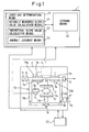
- Fig. 1 is a schematic diagram of a gas laser oscillator according to the present invention.
- a laser oscillator 2 in the present invention is a gas laser oscillator of a discharge excitation type with a comparatively high output, for example, a carbon dioxide gas laser with an output of 2 kW or greater.
- the laser oscillator 2 includes a circulation path 13. As shown schematically, the circulation path 13 comprises a discharge tube 9, a suction pipe path 13a that sucks a laser gas from substantially the central portion in the longitudinal direction of the discharge tube 9, and a return pipe path 13b for discharging the laser gas to the portions adjacent to both end portions of the discharge tube 9.
- the circulation path 13 is connected to a laser gas pressure change means 18.
- the laser gas pressure change means 18 is capable of supplying and discharging the laser gas to and from the circulation path 13 through a laser gas supply inlet 17 and a laser gas discharge outlet 19 formed in the laser oscillator 2.
- a rear mirror 6 (internal resonator mirror) having partial transmittance is provided and on the other end of the discharge tube 9, an output mirror 8 having partial transmittance is provided.
- the output mirror 8 is made from ZnSe and the inner surface of the output mirror 8 is coated with a partial reflection coating and at the same time, the outer surface of the output mirror 8 is coated with a non-reflection coating.
- a laser power sensor 5 is arranged on the rear side of the rear mirror 6, arranged.
- Each of the discharge sections 29a, 29b includes a pair of discharge electrodes 7a, 7b arranged so as to sandwich the discharge tube 9, respectively. It is assumed that these discharge electrodes 7a, 7b have the same dimensions and are metalized or to which a metal member is attached.
- the discharge electrodes 7a, 7b are connected to a laser power supply 4, for example, a high frequency power supply of 2 MHz.
- the laser power supply 4 freely adjusts the electric power to be supplied to each of the discharge sections 29a, 29b independently.
- a turbo blower 14 is arranged and on the upstream side and downstream side of the turbo blower, heat exchangers 12, 12' are arranged, respectively.
- An inverter 10 connected to the turbo blower 14 supplies electric power to drive the turbo blower 14 while controlling the number of revolutions of the turbo blower 14.
- the laser oscillator 2 is connected to a cooling water circulation system 22 so that the laser gas in the circulation path 13, in particular, the laser gas in the discharge tube 9, etc., is cooled down appropriately.
- an electric power detection section 11 is arranged adjacent to the inverter 10.
- the electric power detection section 11 detects the electric power of the inverter 10 and inputs a monitor signal of the detected electric power to a control section 1, to be described later.
- a pressure sensor 16 is provided in the circulation path 13. The pressure sensor 16 detects the pressure of the laser gas in the circulation path 13 and inputs a signal of the detected pressure to the control section 1 similarly.
- the control section 1 is a digital computer and electrically connected to the laser oscillator 2. As shown schematically, the control section 1 mainly includes a laser gas determination means 31 and a storage means 35.
- the storage means 35 stores programs for driving the laser oscillator 2, operation programs, to be described later, for determining a laser gas etc., and various related data.
- the storage means 35 also serves to temporarily store the detected value of electric power and the detected value of pressure detected by the electric power detection section 11 and the pressure sensor 16, respectively.
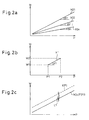
- Fig. 2a is a diagram showing the relationship between the pressure P of the laser gas and electric power W of the turbo blower during the period of normal operation of the turbo blower 14.
- the horizontal axis represents the pressure P of the laser gas in the circulation path 13 and the vertical axis represents the electric power W required to drive the turbo blower 14.
- a plurality of substantially straight solid lines X01 to X0n are shown. These respective solid lines X01 to X0n show the relationship obtained in advance for laser gases having different compositions or composition ratios.
- the density of laser gas differs depending on the composition and composition ratio of the laser gas. Consequently, the electric power of the turbo blower 14 required to circulate the laser gas varies depending on the kind of laser gas used. Because of this, the density of laser gas corresponding to the solid line X01 shown uppermost in Fig. 2a is greater than the densities of laser gas corresponding to other solid lines.
- Fig. 2a the slopes of the respective solid lines X01 to X0n are shown as ideal slope values B1 to Bn. Although not shown schematically, these ideal slope values B1 to Bn are also stored in the storage means 35 for each laser gas G.
- the laser gas determination means 31 includes an actually measured slope value calculation means 32 and a theoretical slope value calculation means 33 for calculating an actually measured slope value and a theoretical slope value, to be described later, respectively. Further, the laser gas determination means 31 also includes an anomaly judgment means 34 for judging whether or not an anomaly occurs in the laser oscillator 2, particularly, in the turbo blower 14.
- the laser gas pressure change means 18 supplies a laser gas into the circulation path 13 through the laser gas supply inlet 17. Then, the laser gas circulates through the circulation path 13 by means of the turbo blower 14 provided in the suction pipe path 13a. As shown by the arrow in Fig. 1, the laser gas sent out from the turbo blower 14 passes through the heat exchanger 12' in order to remove compression heat and is supplied to each of the discharge sections 29a, 29b through the return pipe path 13b.
- a predetermined voltage for example, an alternating voltage of hundreds kHz to tens MHz
- a predetermined voltage for example, an alternating voltage of hundreds kHz to tens MHz
- the laser gas is excited by the discharge operation and due to this, laser beams are generated.
- the laser beam is amplified in an optical resonance space and the laser beam is emitted through the output mirror 8.
- the laser beam emitted from the laser oscillator 2 is supplied to a laser machine (not shown) and used to machine a workpiece (not shown) in the laser machine.
- Fig. 4 is a flow chart showing operation programs for determining the laser gas in the laser oscillator 2 and making an anomaly judgment 2 according to the present invention. It is assumed that the operation program 100 is executed by the laser gas determination means 31 of the control section 1 during the period of operation of the laser oscillator 2. The anomaly judgment of the laser oscillator 2 is explained below with reference to Fig. 4.
- step 101 shown in Fig. 4 pressure P1 of the laser gas in the circulation path 13 is detected with the pressure sensor 16 during the period of normal operation of the turbo blower 14. At the same time, electric power W1 supplied to the turbo blower 14 is detected by the electric power detection section 11.
- step 102 pressure P2 of the laser gas during the period of normal operation and electric power W2 supplied to the turbo blower 14 during the period of normal operation at a different timing from that in step 101 are detected.
- step 103 based on the detected pressures P1, P2 and electric power W1, W2, the actually measured slope value calculation means 32 calculates an actually measured slope value A1.
- the calculated actually measured slope value A1 is, in step 104, compared with a theoretical slope value A0 calculated by the theoretical slope value calculation means 33.
- each of the theoretical slope values A0 calculated for each laser gas G is compared with the actually measured slope value A1 and whether or not there exists any theoretical slope value A0 corresponding to the actually measured slope value A1 is judged. Then, if there exists any theoretical slope value A0 corresponding to the actually measured slope value A1, it is determined that the laser gas G corresponding to the theoretical slope value A0 is the laser gas relating to the actually measured slope value A1, that is, the laser gas currently used in the circulation path 13.
- the gas laser oscillator of the present invention in order to determine a laser gas, it is only required to detect the pressure P and electric power W during the period of normal operation of the turbo blower 14. In other words, when determining a laser gas, it is not necessary to generate discharge voltage. Because of this, in the present invention, the laser power supply 4 and/or the discharge tube 9 does not deteriorate due to the discharge operation when determining a laser gas, and it is also possible to avoid an anomalous discharge when determining a laser gas.
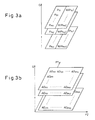
- the theoretical slope values A0 are stored in the storage means 35 in the form of a map as a function of two arbitrary pressures P1, P2 as shown in Fig. 3b.
- the theoretical slope value A0 can be found quickly.
- step 105 whether or not the laser gas could be determined is determined. Then, when the laser gas G could not be determined, that is, there existed no theoretical slope value A0 corresponding to the actually measured slope value A1, the procedure proceeds to step 111, where the anomaly judgment means 34 judges that the laser oscillator 2 is anomalous and terminates the procedure.
- step 106 when the laser gas could be determined, it is judged that there is no anomaly (in step 106) and then the procedure proceeds to step 107.
- step 107 an expression f (P) representative of the segment X1 shown in Fig. 2b is calculated.
- the pressures P1, P2 and electric power W1, W2 detected in steps 101, 102 are used.
- step 108 an expression F (P) corresponding to the expression f (P) is acquired. This is sufficient to formulate the expression F (P) using the relationship (refer to Fig. 3a) between the pressure P and the electric power W corresponding to the laser gas G determined in step 104.
- the formulated expression F (P) corresponds to one of the solid lines X01 to X0n shown in Fig. 2a.
- step 109 the deviation (f (P) - F (P)) obtained by subtracting the expression F (P) from the expression f (P), is compared with a predetermined threshold value L1.
- the predetermined threshold value L1 is a value found in advance for each kind of laser gas by experiments etc. and stored in the storage means 35.
- the anomaly judgment means 34 judges that the laser oscillator 2 is anomalous.
- the anomaly judgment means 34 judges that there is no anomaly in the laser oscillator 2 and terminates the procedure.
- the anomaly judgment means 34 as described above is provided in the present invention, it is possible to notify an operator that the laser oscillator is anomalous and avoid the use of the gas laser oscillator when it is in an anomalous state.
Landscapes
- Physics & Mathematics (AREA)
- Electromagnetism (AREA)
- Engineering & Computer Science (AREA)
- Plasma & Fusion (AREA)
- Optics & Photonics (AREA)
- Lasers (AREA)
Abstract
Description
- The present invention relates to a gas laser oscillator that excites a gas to obtain laser output.
- A general gas laser oscillator excites a laser gas sealed in a discharge tube by discharge energy between discharge electrodes, and generates laser light having an oscillation wavelength corresponding to the amount of energy emitted when a molecule or atom of the gas in the excited state transits to a lower energy level.
- In such a gas laser oscillator, an optimum composition of a laser gas is determined in advance. Then, the pressure of the laser gas in the gas laser oscillator is set to be optimum based on the laser gas having that composition.
- When the composition of an optimum laser gas is different from the composition determined in advance and/or the pressure setting of the laser gas in the gas laser oscillator is different from the pressure setting determined in advance, it is not possible to obtain an optimum laser output.
- Because of this, in
Japanese Unexamined Patent Publication (Kokai) No. 2001-44534 Japanese Unexamined Patent Publication (Kokai) No. 2001-44534 - However, in
Japanese Unexamined Patent Publication (Kokai) No. 2001-44534 Japanese Unexamined Patent Publication (Kokai) No. 2001-44534 - The present invention has been developed taking the above into consideration, and an object thereof is to provide a gas laser oscillator capable of determining a laser gas without generating a discharge voltage.
- In order to attain the above-described object, according to a first aspect, there is provided a gas laser oscillator that excites a laser gas to generate laser light, comprising: a circulation path for the laser gas; a circulation means for circulating the laser gas through the circulation path; a pressure detection means for detecting the pressure of the laser gas in the circulation path; an electric power detection means for detecting electric power to drive the circulation means; a storage means for storing the relationship between the pressure of the laser gas and the electric power of the circulation means during a period of normal operation of the circulation means for each kind of laser gas; and a laser gas determination means for determining the kind of laser gas based on the pressure of the laser gas and the electric power of the circulation means detected by the pressure detection means and the electric power detection means, respectively, during the period of normal operation of the circulation means; and the relationship between the pressure of the laser gas and the electric power of the circulation means stored in the storage means.
- In other words, in the first aspect, when the laser gas is determined, the kind of laser gas is determined based on the pressure and electric power of the circulation means, such as a turbo blower during the period of normal operation. That is, when the laser gas is determined, it is not necessary to generate discharge voltage. Due to this, when the laser gas is determined, a part of the laser oscillator, for example, the laser power supply and/or the discharge tube does not deteriorate, and further, it is possible to avoid a risk of an anomalous discharge when the laser gas is determined.
- According to a second aspect, there is further provided in the first aspect an anomaly judgment means for judging that the gas laser oscillator is anomalous when the kind of laser gas cannot be determined by the laser gas determination means.
- According to a third aspect, there is further provided in the first aspect an anomaly judgment means for judging that the gas laser oscillator is anomalous when the deviation between: the relationship between the pressure of the laser gas and the electric power of the circulation means detected by the pressure detection means and the electric power detection means, respectively, during the period of normal operation of the circulation means; and the relationship between the pressure of the laser gas and the electric power of the circulation means stored in the storage means is greater than a predetermined value.
- In other words, in the second and third aspects, the fact that the gas laser oscillator is anomalous is notified to an operator, and by this, it is possible to avoid the use of the gas laser oscillator in an anomalous state.
- According to a fourth aspect, in any one of the first to third aspects, the pressure of the laser gas and the electric power of the circulation means are simultaneously detected by the pressure detection means and the electric power detection means, respectively.
- In other words, in the fourth aspect, it is possible to improve the accuracy of determining the laser gas.
- According to a fifth aspect, there are provided in any one of the first to fourth aspects an actually measured slope value calculation means for calculating the amount of change in the detected electric power with respect to the amount of change in the detected pressure as an actually measured slope value when the pressure of the laser gas and the electric power of the circulation means are detected at least twice by the pressure detection means and the electric power detection means, respectively, and a theoretical slope value calculation means for calculating the amount of change in the electric power with respect to the amount of change in the detected pressure as a theoretical slope value for each kind of the laser gas using the relationship between the pressure of the laser gas and the electric power of the circulation means stored in the storage means, wherein it is possible for the laser gas determination means to determine the kind of the laser gas further based on the actually measured slope value calculated by the actually measured slope value calculation means and the theoretical slope value calculated by the theoretical slope value calculation means.
- In other words, in the fifth aspect, the theoretical slope value relating to the specific two pressures designated by the operator are calculated, and therefore, it is possible to more accurately determine a laser gas.
- According to a sixth aspect, there is provided in any one of the first to fourth aspects an actually measured slope value calculation means for calculating the amount of change in the detected electric power with respect to the amount of change in the detected pressure as an actually measured slope value when the pressure of the laser gas and the electric power of the circulation means are detected at least twice by the pressure detection means and the electric power detection means, respectively, wherein it is possible for the laser gas determination means to determine the kind of the laser gas further based on the actually measured slope value calculated by the actually measured slope value calculation means and the slope for each kind of laser gas in the relationship between the pressure of the laser gas and the electric power of the circulation means stored in the storage means.
- In other words, in the sixth aspect, the slope in the relationship between the pressure of the laser gas and the electric power of the circulation means has already been determined, and therefore, by using the slope as an ideal slope value instead of a theoretical slope value, it is possible to more quickly determine a laser gas compared to the case where the theoretical value of slope is calculated each time.
- These and other objects, features and advantages of the present invention will be more apparent in light of the detailed description of exemplary embodiments thereof as illustrated by the drawings.
-
- Fig. 1 is a schematic diagram of a gas laser oscillator according to the present invention.
- Fig. 2a is a diagram showing the relationship between the pressure of laser gas and the electric power of a turbo blower during a period of normal operation of the turbo blower.
- Fig. 2b is a diagram similar to Fig. 2a explaining an actually measured slope value.
- Fig. 2c is a diagram similar to Fig. 2a showing the relationship between the pressure of a laser gas and the electric power of a turbo blower.
- Fig. 3a is a diagram showing a map of pressure P and electric power W.
- Fig. 3b is a diagram showing a map of theoretical slope value A0.
- Fig. 4 is a flow chart showing operation programs for determining a laser gas and making an anomaly judgment in a laser oscillator according to the present invention.
- The embodiments of the present invention are explained below with reference to the accompanied drawings. In the following drawings, the same members are assigned like reference numerals, and for easier understanding, the scale of these drawings has been adjusted appropriately.
- Fig. 1 is a schematic diagram of a gas laser oscillator according to the present invention. A
laser oscillator 2 in the present invention is a gas laser oscillator of a discharge excitation type with a comparatively high output, for example, a carbon dioxide gas laser with an output of 2 kW or greater. Thelaser oscillator 2 includes acirculation path 13. As shown schematically, thecirculation path 13 comprises adischarge tube 9, asuction pipe path 13a that sucks a laser gas from substantially the central portion in the longitudinal direction of thedischarge tube 9, and areturn pipe path 13b for discharging the laser gas to the portions adjacent to both end portions of thedischarge tube 9. - The
circulation path 13 is connected to a laser gas pressure change means 18. The laser gas pressure change means 18 is capable of supplying and discharging the laser gas to and from thecirculation path 13 through a lasergas supply inlet 17 and a lasergas discharge outlet 19 formed in thelaser oscillator 2. - On one end of the
discharge tube 9, a rear mirror 6 (internal resonator mirror) having partial transmittance is provided and on the other end of thedischarge tube 9, anoutput mirror 8 having partial transmittance is provided. Theoutput mirror 8 is made from ZnSe and the inner surface of theoutput mirror 8 is coated with a partial reflection coating and at the same time, the outer surface of theoutput mirror 8 is coated with a non-reflection coating. On the rear side of therear mirror 6, alaser power sensor 5 is arranged. - In an optical resonance space between the
rear mirror 6 and theoutput mirror 8, twodischarge sections discharge sections discharge electrodes discharge tube 9, respectively. It is assumed that thesedischarge electrodes - As shown in Fig. 1, the
discharge electrodes discharge sections - In addition, in the
suction pipe path 13a of thecirculation path 13, aturbo blower 14 is arranged and on the upstream side and downstream side of the turbo blower,heat exchangers 12, 12' are arranged, respectively. Aninverter 10 connected to theturbo blower 14 supplies electric power to drive theturbo blower 14 while controlling the number of revolutions of theturbo blower 14. Further, thelaser oscillator 2 is connected to a coolingwater circulation system 22 so that the laser gas in thecirculation path 13, in particular, the laser gas in thedischarge tube 9, etc., is cooled down appropriately. - As shown in Fig. 1, in the present invention, an electric
power detection section 11 is arranged adjacent to theinverter 10. The electricpower detection section 11 detects the electric power of theinverter 10 and inputs a monitor signal of the detected electric power to a control section 1, to be described later. In addition, as shown schematically, apressure sensor 16 is provided in thecirculation path 13. Thepressure sensor 16 detects the pressure of the laser gas in thecirculation path 13 and inputs a signal of the detected pressure to the control section 1 similarly. - The control section 1 is a digital computer and electrically connected to the
laser oscillator 2. As shown schematically, the control section 1 mainly includes a laser gas determination means 31 and a storage means 35. The storage means 35 stores programs for driving thelaser oscillator 2, operation programs, to be described later, for determining a laser gas etc., and various related data. In addition, the storage means 35 also serves to temporarily store the detected value of electric power and the detected value of pressure detected by the electricpower detection section 11 and thepressure sensor 16, respectively. - Fig. 2a is a diagram showing the relationship between the pressure P of the laser gas and electric power W of the turbo blower during the period of normal operation of the
turbo blower 14. In Fig. 2a, the horizontal axis represents the pressure P of the laser gas in thecirculation path 13 and the vertical axis represents the electric power W required to drive theturbo blower 14. - In Fig. 2a, a plurality of substantially straight solid lines X01 to X0n are shown. These respective solid lines X01 to X0n show the relationship obtained in advance for laser gases having different compositions or composition ratios. In general, the density of laser gas differs depending on the composition and composition ratio of the laser gas. Consequently, the electric power of the
turbo blower 14 required to circulate the laser gas varies depending on the kind of laser gas used. Because of this, the density of laser gas corresponding to the solid line X01 shown uppermost in Fig. 2a is greater than the densities of laser gas corresponding to other solid lines. - It is assumed that the relationship between the pressure P and the electric power W during the period of normal operation of the
turbo blower 14 as shown in Fig. 2a are stored in advance in the storage means 35 of the control section 1. Specifically, such relationships are found in advance for each laser gas G by experimentation, etc. and stored in the form of a map, as shown in Fig. 3a. - In Fig. 2a, the slopes of the respective solid lines X01 to X0n are shown as ideal slope values B1 to Bn. Although not shown schematically, these ideal slope values B1 to Bn are also stored in the storage means 35 for each laser gas G.
- Referring to Fig. 1 again, the laser gas determination means 31 includes an actually measured slope value calculation means 32 and a theoretical slope value calculation means 33 for calculating an actually measured slope value and a theoretical slope value, to be described later, respectively. Further, the laser gas determination means 31 also includes an anomaly judgment means 34 for judging whether or not an anomaly occurs in the
laser oscillator 2, particularly, in theturbo blower 14. - During the period of operation of the
laser oscillator 2 as shown in Fig. 1, the laser gas pressure change means 18 supplies a laser gas into thecirculation path 13 through the lasergas supply inlet 17. Then, the laser gas circulates through thecirculation path 13 by means of theturbo blower 14 provided in thesuction pipe path 13a. As shown by the arrow in Fig. 1, the laser gas sent out from theturbo blower 14 passes through the heat exchanger 12' in order to remove compression heat and is supplied to each of thedischarge sections return pipe path 13b. - When a predetermined voltage, for example, an alternating voltage of hundreds kHz to tens MHz, is applied to the
discharge sections discharge electrodes output mirror 8. The laser beam emitted from thelaser oscillator 2 is supplied to a laser machine (not shown) and used to machine a workpiece (not shown) in the laser machine. - Laser gas temperature of which has risen due to the discharge operation is cooled down by the
heat exchanger 12 and returns to theturbo blower 14 again. At this time, it is assumed that the coolingwater circulation system 22 operates so that the laser gas in thedischarge tube 9 is cooled down appropriately. - Fig. 4 is a flow chart showing operation programs for determining the laser gas in the
laser oscillator 2 and making ananomaly judgment 2 according to the present invention. It is assumed that theoperation program 100 is executed by the laser gas determination means 31 of the control section 1 during the period of operation of thelaser oscillator 2. The anomaly judgment of thelaser oscillator 2 is explained below with reference to Fig. 4. - In
step 101 shown in Fig. 4, pressure P1 of the laser gas in thecirculation path 13 is detected with thepressure sensor 16 during the period of normal operation of theturbo blower 14. At the same time, electric power W1 supplied to theturbo blower 14 is detected by the electricpower detection section 11. Next, instep 102, pressure P2 of the laser gas during the period of normal operation and electric power W2 supplied to theturbo blower 14 during the period of normal operation at a different timing from that instep 101 are detected. - Next, in
step 103, based on the detected pressures P1, P2 and electric power W1, W2, the actually measured slope value calculation means 32 calculates an actually measured slope value A1. Fig. 2b is a diagram similar to Fig. 2a explaining the actually measured slope value. As shown in Fig. 2b, the detected pressures P1, P2 and electric power W1, W2 are plotted on a pressure-electric power plane and thus a segment X1 is constructed. Then, the actually measured slope value calculation means 32 calculates the slope of the segment X1 as the actually measured slope value A1 (= (W2 - W1) / (P2 - P1)). - The calculated actually measured slope value A1 is, in
step 104, compared with a theoretical slope value A0 calculated by the theoretical slope value calculation means 33. The theoretical slope value calculation means 33 first determines the electric power W (P1), W (P2) corresponding to the above-described pressure P1 and pressure P2 for each laser gas G using the map shown in Fig. 3a. Then, the theoretical slope value calculation means 33 calculates the theoretical slope value A0 (= (W (P2) - W (P1)) / (P2 - P1)) for each laser gas G. - After that, each of the theoretical slope values A0 calculated for each laser gas G is compared with the actually measured slope value A1 and whether or not there exists any theoretical slope value A0 corresponding to the actually measured slope value A1 is judged. Then, if there exists any theoretical slope value A0 corresponding to the actually measured slope value A1, it is determined that the laser gas G corresponding to the theoretical slope value A0 is the laser gas relating to the actually measured slope value A1, that is, the laser gas currently used in the
circulation path 13. - Thus, in the gas laser oscillator of the present invention, in order to determine a laser gas, it is only required to detect the pressure P and electric power W during the period of normal operation of the
turbo blower 14. In other words, when determining a laser gas, it is not necessary to generate discharge voltage. Because of this, in the present invention, the laser power supply 4 and/or thedischarge tube 9 does not deteriorate due to the discharge operation when determining a laser gas, and it is also possible to avoid an anomalous discharge when determining a laser gas. - In the other embodiments, the theoretical slope values A0 are stored in the storage means 35 in the form of a map as a function of two arbitrary pressures P1, P2 as shown in Fig. 3b. Thus, it also may be possible to find the theoretical slope value A0 without using a calculating expression. In this case, it will be appreciated that the theoretical slope value A0 can be found quickly.
- After that, in
step 105, whether or not the laser gas could be determined is determined. Then, when the laser gas G could not be determined, that is, there existed no theoretical slope value A0 corresponding to the actually measured slope value A1, the procedure proceeds to step 111, where the anomaly judgment means 34 judges that thelaser oscillator 2 is anomalous and terminates the procedure. - On the other hand, when the laser gas could be determined, it is judged that there is no anomaly (in step 106) and then the procedure proceeds to step 107. In
step 107, an expression f (P) representative of the segment X1 shown in Fig. 2b is calculated. When calculating the expression f (P), the pressures P1, P2 and electric power W1, W2 detected insteps - Next, in
step 108, an expression F (P) corresponding to the expression f (P) is acquired. This is sufficient to formulate the expression F (P) using the relationship (refer to Fig. 3a) between the pressure P and the electric power W corresponding to the laser gas G determined instep 104. Incidentally, it should be noted that the formulated expression F (P) corresponds to one of the solid lines X01 to X0n shown in Fig. 2a. - Next, in
step 109, the deviation (f (P) - F (P)) obtained by subtracting the expression F (P) from the expression f (P), is compared with a predetermined threshold value L1. The predetermined threshold value L1 is a value found in advance for each kind of laser gas by experiments etc. and stored in the storage means 35. - As can be seen by referring to Fig. 2(c), when the deviation (f (P) - F (P)) is greater than the predetermined threshold value L1, it means that the expression f (P) is considerably different from the expression F (P). The causes of the difference of the expression f (P) from the expression F (P) include, for example, the fact that a bearing (not shown) used in the
turbo blower 14 is broken and the torque increases and the fact that electric power increases because of leak etc. In such a case, instep 111, the anomaly judgment means 34 judges that thelaser oscillator 2 is anomalous. - On the other hand, when the deviation (f (P) - F (P)) is equal to or less than the predetermined threshold value L1, that is, the expression f (P) is substantially equal to the expression F (P) or slightly greater than the expression F (P), it can be regarded that the expression f (P) is different from the expression F (P) within a measurement error. Consequently, in this case, in
step 110, the anomaly judgment means 34 judges that there is no anomaly in thelaser oscillator 2 and terminates the procedure. - It will be appreciated that since the anomaly judgment means 34 as described above is provided in the present invention, it is possible to notify an operator that the laser oscillator is anomalous and avoid the use of the gas laser oscillator when it is in an anomalous state.
- In addition, in the other embodiments of the present invention, it also may be possible to use the respective ideal slope values B1 to Bn (refer to Fig. 2a) for the respective solid lines X01 to X0n. In this case, it is not necessary to calculate the theoretical slope value A0 corresponding to the specific pressures P1, P2 in
step 104. Consequently, it is possible to determine a laser gas more quickly than compared with a case where the theoretical slope value is calculated each time. - As a matter of course, it also may be possible to calculate the actually measured slope value A1 after detecting the pressure P and the electric power W three times or more. In addition, it may also be possible to calculate the flow rate of the laser gas in the
circulation path 13 using the pressure P of the laser gas and determine the kind of the laser gas from the relationship between the flow rate of the laser gas found in advance and the electric power W. It is apparent that such a case is also included in the scope of the present invention. - Although the invention has been shown and described with exemplary embodiments thereof, it should be understood by those skilled in the art that the foregoing and various other changes, omissions and additions may be made therein and thereto without departing from the scope of the invention.
Claims (6)
- A gas laser oscillator (2) that excites a laser gas to generate laser light, comprising:a circulation path (13) for the laser gas;a circulation means (14) for circulating the laser gas through the circulation path (13);a pressure detection means (16) for detecting the pressure of the laser gas in the circulation path (13);an electric power detection means (11) for detecting electric power to drive the circulation means (14);a storage means (35) for storing the relationship between the pressure of the laser gas and the electric power of the circulation means (14) during the period of normal operation of the circulation means (14) for each kind of the laser gas; anda laser gas determination means (31) for determining the kind of the laser gas based on the pressure of the laser gas and the electric power of the circulation means (14) detected respectively by the pressure detection means (16) and the electric power detection means (11) during the period of normal operation of the circulation means (14), and the relationship between the pressure of the laser gas and the electric power of the circulation means (14) stored in the storage means.
- The gas laser oscillator as set forth in claim 1, further comprising an anomaly judgment means (34) for judging that the gas laser oscillator (2) is anomalous when the kind of the laser gas cannot be determined by the laser gas determination means (31).
- The gas laser oscillator as set forth in claim 1, further comprising an anomaly judgment means (34) for judging that the gas laser oscillator (2) is anomalous when the deviation between: the relationship between the pressure of the laser gas and the electric power of the circulation means (14) detected respectively by the pressure detection means (16) and the electric power detection means (11) during the period of normal operation of the circulation means (14); and the relationship between the pressure of the laser gas and the electric power of the circulation means (14) stored in the storage means (35) is equal to or greater than a predetermined value.
- The gas laser oscillator as set forth in any one of claims 1 to 3, wherein the pressure of the laser gas and the electric power of the circulation means (14) are simultaneously detected by the pressure detection means (16) and the electric power detection means (11), respectively.
- The gas laser oscillator as set forth in any one of claims 1 to 4, further comprising:an actually measured slope value calculation means (32) for calculating the amount of change in the detected electric power with respect to the amount of change in the detected pressure as an actually measured slope value when the pressure of the laser gas and the electric power of the circulation means (14) are detected at least twice by the pressure detection means (16) and the electric power detection means (11), respectively; anda theoretical slope value calculation means (33) for calculating the amount of change in the electric power with respect to the amount of change in the detected pressure as a theoretical slope value for each kind of the laser gas using the relationship between the pressure of the laser gas and the electric power of the circulation means (14) stored in the storage means (35), whereinthe laser gas determination means (31) determines the kind of the laser gas further based on the actually measured slope value calculated by the actually measured slope value calculation means (32) and the theoretical slope value calculated by the theoretical slope value calculation means (33).
- The gas laser oscillator as set forth in any one of claims 1 to 4, further comprising an actually measured slope value calculation means (32) for calculating the amount of change in the detected electric power with respect to the amount of change in the detected pressure as an actually measured slope value when the presser of the laser gas and the electric power of the circulation means (14) are detected at least twice by the pressure detection means (16) and the electric power detection means (11), respectively, wherein
the laser gas determination means (31) determines the kind of the laser gas further based on the actually measured slope value calculated by the actually measured slope value calculation means (32) and the slope for each kind of the laser gas in the relationship between the pressure of the laser gas and the electric power of the circulation means (14) stored in the storage means (35).
Applications Claiming Priority (1)
| Application Number | Priority Date | Filing Date | Title |
|---|---|---|---|
| JP2006172945A JP4146867B2 (en) | 2006-06-22 | 2006-06-22 | Gas laser oscillator |
Publications (2)
| Publication Number | Publication Date |
|---|---|
| EP1870971A1 true EP1870971A1 (en) | 2007-12-26 |
| EP1870971B1 EP1870971B1 (en) | 2011-03-02 |
Family
ID=38458011
Family Applications (1)
| Application Number | Title | Priority Date | Filing Date |
|---|---|---|---|
| EP07010181A Ceased EP1870971B1 (en) | 2006-06-22 | 2007-05-22 | Gas laser oscillator |
Country Status (5)
| Country | Link |
|---|---|
| US (1) | US7551661B2 (en) |
| EP (1) | EP1870971B1 (en) |
| JP (1) | JP4146867B2 (en) |
| CN (1) | CN100539329C (en) |
| DE (1) | DE602007012796D1 (en) |
Families Citing this family (22)
| Publication number | Priority date | Publication date | Assignee | Title |
|---|---|---|---|---|
| JP5218639B2 (en) * | 2009-03-12 | 2013-06-26 | パナソニック株式会社 | Laser oscillation device and laser processing machine |
| JP4809486B2 (en) | 2010-04-05 | 2011-11-09 | ファナック株式会社 | Gas laser oscillator having a function of determining the start of discharge |
| DK2565994T3 (en) | 2011-09-05 | 2014-03-10 | Alltec Angewandte Laserlicht Technologie Gmbh | Laser device and method for marking an object |
| EP2564976B1 (en) | 2011-09-05 | 2015-06-10 | ALLTEC Angewandte Laserlicht Technologie Gesellschaft mit beschränkter Haftung | Marking apparatus with at least one gas laser and heat dissipator |
| ES2544269T3 (en) * | 2011-09-05 | 2015-08-28 | ALLTEC Angewandte Laserlicht Technologie Gesellschaft mit beschränkter Haftung | Marking apparatus with a plurality of gas lasers with resonance tubes and deflection means individually adjustable |
| EP2565996B1 (en) | 2011-09-05 | 2013-12-11 | ALLTEC Angewandte Laserlicht Technologie Gesellschaft mit beschränkter Haftung | Laser device with a laser unit, and a fluid container for a cooling means of said laser unit |
| EP2565673B1 (en) | 2011-09-05 | 2013-11-13 | ALLTEC Angewandte Laserlicht Technologie Gesellschaft mit beschränkter Haftung | Device and method for marking of an object by means of a laser beam |
| EP2564975B1 (en) * | 2011-09-05 | 2014-12-10 | ALLTEC Angewandte Laserlicht Technologie Gesellschaft mit beschränkter Haftung | Marking apparatus with a plurality of lasers and individually adjustable sets of deflection means |
| EP2564972B1 (en) * | 2011-09-05 | 2015-08-26 | ALLTEC Angewandte Laserlicht Technologie Gesellschaft mit beschränkter Haftung | Marking apparatus with a plurality of lasers, deflection means and telescopic means for each laser beam |
| EP2564973B1 (en) * | 2011-09-05 | 2014-12-10 | ALLTEC Angewandte Laserlicht Technologie Gesellschaft mit beschränkter Haftung | Marking apparatus with a plurality of lasers and a combining deflection device |
| EP2852012B1 (en) * | 2012-05-18 | 2017-02-22 | Panasonic Intellectual Property Management Co., Ltd. | Lasing device |
| JP5661834B2 (en) | 2013-03-05 | 2015-01-28 | ファナック株式会社 | Laser device capable of estimating the sealing property of a laser gas container |
| JP5661841B2 (en) * | 2013-03-26 | 2015-01-28 | ファナック株式会社 | Gas laser oscillator having a function of determining the start of discharge |
| JP5650787B2 (en) * | 2013-04-12 | 2015-01-07 | ファナック株式会社 | Gas laser oscillator having a function of determining the start of discharge |
| JP5850969B2 (en) | 2014-04-03 | 2016-02-03 | ファナック株式会社 | Carbon dioxide laser oscillator capable of estimating the composition ratio of laser gas |
| JP5829311B1 (en) * | 2014-06-18 | 2015-12-09 | ファナック株式会社 | Gas laser oscillator capable of estimating gas tightness |
| JP5941112B2 (en) * | 2014-09-30 | 2016-06-29 | ファナック株式会社 | Laser oscillator to improve beam quality |
| JP6189883B2 (en) * | 2015-01-29 | 2017-08-30 | ファナック株式会社 | Gas laser device for determining composition ratio of laser gas |
| CN106644251A (en) * | 2016-12-29 | 2017-05-10 | 中国科学院长春光学精密机械与物理研究所 | Gas pressure detection device of laser device |
| JP7572172B2 (en) * | 2020-07-03 | 2024-10-23 | 住友重機械工業株式会社 | Laser Oscillator |
| DE102022204308A1 (en) | 2022-05-02 | 2023-11-02 | Trumpf Lasersystems For Semiconductor Manufacturing Gmbh | Indirectly monitored laser system |
| CN119812892B (en) * | 2025-03-14 | 2025-06-13 | 文皓(南京)科技有限责任公司 | Automatic gas filling control method and device for gas laser |
Citations (4)
| Publication number | Priority date | Publication date | Assignee | Title |
|---|---|---|---|---|
| JPH01128581A (en) * | 1987-11-13 | 1989-05-22 | Toshiba Corp | Gas laser apparatus |
| JPH0352281A (en) * | 1989-07-20 | 1991-03-06 | Fanuc Ltd | Gas laser oscillator |
| US6366039B1 (en) * | 1999-04-21 | 2002-04-02 | Ebara Corporation | Excimer laser device |
| WO2005104308A1 (en) * | 2004-04-21 | 2005-11-03 | Mitsubishi Denki Kabushiki Kaisha | Gas laser oscillator and gas laser material processing machine |
Family Cites Families (3)
| Publication number | Priority date | Publication date | Assignee | Title |
|---|---|---|---|---|
| US5377215A (en) * | 1992-11-13 | 1994-12-27 | Cymer Laser Technologies | Excimer laser |
| JP2816813B2 (en) * | 1994-04-12 | 1998-10-27 | 株式会社小松製作所 | Excimer laser device |
| JP2001044534A (en) | 1999-06-07 | 2001-02-16 | Lambda Physik G Zur Herstellung Von Lasern Mbh | Method and apparatus for maintaining composition of gas mixture for gas discharge laser |
-
2006
- 2006-06-22 JP JP2006172945A patent/JP4146867B2/en not_active Expired - Fee Related
-
2007
- 2007-05-22 EP EP07010181A patent/EP1870971B1/en not_active Ceased
- 2007-05-22 DE DE602007012796T patent/DE602007012796D1/en active Active
- 2007-05-30 US US11/755,013 patent/US7551661B2/en not_active Expired - Fee Related
- 2007-06-19 CN CNB2007101125080A patent/CN100539329C/en not_active Expired - Fee Related
Patent Citations (4)
| Publication number | Priority date | Publication date | Assignee | Title |
|---|---|---|---|---|
| JPH01128581A (en) * | 1987-11-13 | 1989-05-22 | Toshiba Corp | Gas laser apparatus |
| JPH0352281A (en) * | 1989-07-20 | 1991-03-06 | Fanuc Ltd | Gas laser oscillator |
| US6366039B1 (en) * | 1999-04-21 | 2002-04-02 | Ebara Corporation | Excimer laser device |
| WO2005104308A1 (en) * | 2004-04-21 | 2005-11-03 | Mitsubishi Denki Kabushiki Kaisha | Gas laser oscillator and gas laser material processing machine |
Non-Patent Citations (1)
| Title |
|---|
| HONG-SIK LEE; YOON-TAEK KIM: "Instrumentation of an RF excited fast axial flow carbon dioxide laser and its operation characteristics", TRANSACTIONS OF THE KOREAN INSTITUTE OF ELECTRICAL ENGINEERS, vol. 46, no. 5, May 1997 (1997-05-01), pages 807 - 812, XP009089289 * |
Also Published As
| Publication number | Publication date |
|---|---|
| US20080043799A1 (en) | 2008-02-21 |
| EP1870971B1 (en) | 2011-03-02 |
| CN100539329C (en) | 2009-09-09 |
| CN101093927A (en) | 2007-12-26 |
| DE602007012796D1 (en) | 2011-04-14 |
| JP2008004773A (en) | 2008-01-10 |
| US7551661B2 (en) | 2009-06-23 |
| JP4146867B2 (en) | 2008-09-10 |
Similar Documents
| Publication | Publication Date | Title |
|---|---|---|
| US7551661B2 (en) | Gas laser oscillator | |
| EP2079135A2 (en) | Abnormality detection method for gas laser oscillator and gas laser oscillator for implementing the method | |
| US6818856B2 (en) | Laser machining apparatus | |
| US7257136B2 (en) | Laser apparatus | |
| US20110243177A1 (en) | Gas laser device | |
| JP2013201433A (en) | Multi-chambered excimer or molecular fluorine gas discharge laser fluorine injection control | |
| JP6310390B2 (en) | Laser apparatus control method and laser apparatus | |
| US8428092B2 (en) | High-power laser unit wherein laser output can be accurately corrected | |
| CN103988378B (en) | Lasing device | |
| EP1667291A2 (en) | Gas laser oscillator | |
| US7720118B2 (en) | Laser unit having preparatory function for activating the unit and activation method for the unit | |
| US20050195867A1 (en) | Laser unit | |
| JP4137972B2 (en) | Gas composition abnormality judgment method and discharge excitation gas laser oscillator | |
| US9379511B2 (en) | Laser oscillator and laser machining apparatus | |
| US20080304533A1 (en) | Startup method for gas laser unit and gas laser unit having startup function | |
| US20080025352A1 (en) | Laser apparatus having ability to automatically correct laser beam power | |
| JP2006216867A (en) | Laser oscillator output correction method and laser oscillator | |
| JP4598852B2 (en) | Method for discriminating disappearance of auxiliary discharge with gas laser oscillator and gas laser oscillator | |
| US20150236469A1 (en) | Gas laser apparatus carrying out improved startup process | |
| JP3986746B2 (en) | Gas laser oscillator | |
| JPH04199756A (en) | Stabilizing device for excimer laser output | |
| JP2001274485A (en) | Gas laser oscillation device | |
| JP2009049312A (en) | Laser oscillator with mirror angle adjusting mechanism part |
Legal Events
| Date | Code | Title | Description |
|---|---|---|---|
| PUAI | Public reference made under article 153(3) epc to a published international application that has entered the european phase |
Free format text: ORIGINAL CODE: 0009012 |
|
| AK | Designated contracting states |
Kind code of ref document: A1 Designated state(s): AT BE BG CH CY CZ DE DK EE ES FI FR GB GR HU IE IS IT LI LT LU LV MC MT NL PL PT RO SE SI SK TR |
|
| AX | Request for extension of the european patent |
Extension state: AL BA HR MK YU |
|
| 17P | Request for examination filed |
Effective date: 20080108 |
|
| 17Q | First examination report despatched |
Effective date: 20080214 |
|
| AKX | Designation fees paid |
Designated state(s): DE |
|
| GRAP | Despatch of communication of intention to grant a patent |
Free format text: ORIGINAL CODE: EPIDOSNIGR1 |
|
| GRAS | Grant fee paid |
Free format text: ORIGINAL CODE: EPIDOSNIGR3 |
|
| GRAA | (expected) grant |
Free format text: ORIGINAL CODE: 0009210 |
|
| RAP1 | Party data changed (applicant data changed or rights of an application transferred) |
Owner name: FANUC CORPORATION |
|
| AK | Designated contracting states |
Kind code of ref document: B1 Designated state(s): DE |
|
| REF | Corresponds to: |
Ref document number: 602007012796 Country of ref document: DE Date of ref document: 20110414 Kind code of ref document: P |
|
| REG | Reference to a national code |
Ref country code: DE Ref legal event code: R096 Ref document number: 602007012796 Country of ref document: DE Effective date: 20110414 |
|
| PLBE | No opposition filed within time limit |
Free format text: ORIGINAL CODE: 0009261 |
|
| STAA | Information on the status of an ep patent application or granted ep patent |
Free format text: STATUS: NO OPPOSITION FILED WITHIN TIME LIMIT |
|
| 26N | No opposition filed |
Effective date: 20111205 |
|
| REG | Reference to a national code |
Ref country code: DE Ref legal event code: R097 Ref document number: 602007012796 Country of ref document: DE Effective date: 20111205 |
|
| PGFP | Annual fee paid to national office [announced via postgrant information from national office to epo] |
Ref country code: DE Payment date: 20210427 Year of fee payment: 15 |
|
| REG | Reference to a national code |
Ref country code: DE Ref legal event code: R119 Ref document number: 602007012796 Country of ref document: DE |
|
| PG25 | Lapsed in a contracting state [announced via postgrant information from national office to epo] |
Ref country code: DE Free format text: LAPSE BECAUSE OF NON-PAYMENT OF DUE FEES Effective date: 20221201 |