EP1870750A2 - Cassette for optical cables, support rail and assembly for stacking such cassettes - Google Patents
Cassette for optical cables, support rail and assembly for stacking such cassettes Download PDFInfo
- Publication number
- EP1870750A2 EP1870750A2 EP07301127A EP07301127A EP1870750A2 EP 1870750 A2 EP1870750 A2 EP 1870750A2 EP 07301127 A EP07301127 A EP 07301127A EP 07301127 A EP07301127 A EP 07301127A EP 1870750 A2 EP1870750 A2 EP 1870750A2
- Authority
- EP
- European Patent Office
- Prior art keywords
- cassette
- arrangement
- cassettes
- rail
- articulation
- Prior art date
- Legal status (The legal status is an assumption and is not a legal conclusion. Google has not performed a legal analysis and makes no representation as to the accuracy of the status listed.)
- Granted
Links
Images


Classifications
-
- G—PHYSICS
- G02—OPTICS
- G02B—OPTICAL ELEMENTS, SYSTEMS OR APPARATUS
- G02B6/00—Light guides; Structural details of arrangements comprising light guides and other optical elements, e.g. couplings
- G02B6/44—Mechanical structures for providing tensile strength and external protection for fibres, e.g. optical transmission cables
- G02B6/4439—Auxiliary devices
- G02B6/444—Systems or boxes with surplus lengths
- G02B6/4453—Cassettes
- G02B6/4455—Cassettes characterised by the way of extraction or insertion of the cassette in the distribution frame, e.g. pivoting, sliding, rotating or gliding
Landscapes
- Physics & Mathematics (AREA)
- General Physics & Mathematics (AREA)
- Optics & Photonics (AREA)
- Light Guides In General And Applications Therefor (AREA)
- Mechanical Coupling Of Light Guides (AREA)
- Electric Cable Arrangement Between Relatively Moving Parts (AREA)
- Cable Accessories (AREA)
- Storage Of Web-Like Or Filamentary Materials (AREA)
- Packaging Of Annular Or Rod-Shaped Articles, Wearing Apparel, Cassettes, Or The Like (AREA)
Abstract
Description
L'invention concerne un cassette pour câbles optiques, un rail de support destiné à former un ensemble d'empilage de cassettes par association avec au moins deux cassettes et un ensemble d'empilage de telles cassettes.The invention relates to a cassette for optical cables, a support rail for forming a cassette stacking assembly by association with at least two cassettes and a stacking assembly of such cassettes.
Une telle cassette est une boîte de lovage et de protection de fibres optiques et souvent également de protection de raccords entre les fibres optiques lovées. De telles cassettes sont utilisées pour le raccordement d'un câble optique ou de différents câbles optiques à des jarretières optiques. Chaque cassette est affectée à deux fibres optiques à raccorder l'une à l'autre ou à plusieurs fibres à raccorder individuellement à plusieurs autres fibres.Such a cassette is a box of coiling and protection of optical fibers and often also protection of connections between the optical fibers coiled. Such cassettes are used for connecting an optical cable or different optical cables to optical jumpers. Each cassette is assigned to two optical fibers to be connected to each other or to several fibers to be individually connected to several other fibers.
Plusieurs cassettes sont en général affectées au traitement de la totalité des fibres d'un ou de plusieurs câbles optiques à raccorder à un ou d'autres câbles optiques ou des jarretières dans un boîtier de raccordement.Several cassettes are generally assigned to the processing of all fibers of one or more optical cables to be connected to one or other optical cables or jumpers in a junction box.
Le modèle d'utilité
Cet ensemble comprend un rail de maintien comportant deux brides perforées dont chaque paire de perforations en vis-à-vis peut recevoir une pièce d'articulation d'une cassette. Ce rail peut être fixé dans un boîtier de sorte à être incliné de 45° par rapport à une paroi de ce boîtier. Les cassettes superposées et articulées sur le rail sont alors décalées les unes des autres, dans une position d'empilage dite à 45° correspondant à l'inclinaison de l'axe passant par le centre de chacune d'elles. L'articulation sur le rail est réalisée par emmanchement axial de deux tenons de même direction dans chaque paire de perforations du rail et blocage par une languette de clippage.This assembly comprises a retaining rail comprising two perforated flanges each pair of perforations vis-à-vis can receive a hinge part of a cassette. This rail can be fixed in a housing so as to be inclined by 45 ° with respect to a wall of this housing. The superimposed and articulated cassettes on the rail are then offset from each other, in a so-called stacking position at 45 ° corresponding to the inclination of the axis passing through the center of each of them. The articulation on the rail is carried out by axial fitting of two tenons of the same direction in each pair of perforations of the rail and locking by a clipping tab.
Les mêmes cassettes peuvent également être empilées dans une position dite à 90° correspondant à l'inclinaison de l'axe passant par le centre de chacune d'elles, cette fois sans rail. Dans ce cas, un clip indépendant est encliqueté sur respectivement un axe se trouvant sur le bord de deux cassettes adjacentes et forme ainsi une charnière entre chaque paire de cassettes.The same cassettes can also be stacked in a so-called 90 ° position corresponding to the inclination of the axis passing through the center of each of them, this time without a rail. In this case, an independent clip is snapped onto an axis located on the edge of two adjacent cassettes and thus forms a hinge between each pair of cassettes.
Ce type de cassettes pose le problème technique suivant.This type of cassette poses the following technical problem.
Dans le cas d'un empilage à 45°, il n'est prévu aucun verrouillage mutuel entre paire de cassettes adjacentes. Lorsque l'on veut accéder à une cassette quelconque de l'empilage pour des raisons de maintenance par exemple, il faut relever les cassettes qui lui sont supérieures et les maintenir dans cette position relevée grâce par exemple à un moyen séparé de type bande élastique ou bande « Velcro ».In the case of 45 ° stacking, there is no mutual interlock between pairs of adjacent cassettes. When one wants to access any cassette of the stack for maintenance reasons for example, it is necessary to raise the cassettes which are superior to it and keep them in this raised position thanks for example to a separate means of elastic band type or Velcro tape.
Il pourrait être envisagé d'utiliser des clips de même type que ceux décrit pour un empilage à 90°. Mais ces clips constituent des pièces de petites taille délicates à monter, nécessitant un outil de type pince ou tournevis pour leur démontage et dont il faut gérer le stockage en tant que pièce détachée.It could be envisaged to use clips of the same type as those described for a 90 ° stack. But these clips are small pieces difficult to assemble, requiring a pliers tool or screwdriver for disassembly and which must manage the storage as a spare part.
Par ailleurs, le document de brevet
L'invention résout ce problème en proposant une cassette de lovage et de raccordement de fibres optiques comportant un agencement de verrouillage par paire de cassettes empilées dans une position d'empilage à 90°, cet agencement étant intégré à la cassette caractérisée en ce que ledit agencement de verrouillage assure également le verrouillage par paire de cassettes empilées dans une position d'empilage incliné.The invention solves this problem by providing a fiber optic splicing and connecting cassette having a pair locking arrangement of stacked cassettes in a 90 ° stacking position, which arrangement is integrated with the cassette characterized in that said The locking arrangement also locks pairs of stacked cassettes in an inclined stacking position.
Selon un mode de réalisation préféré, ledit agencement de verrouillage est constitué d'au moins une bride présentant sur une des faces de la cassette au moins un tenon d'encliquetage et sur l'autre face de la cassette au moins trois orifices d'encliquetage alignés selon un axe de sorte à pouvoir recevoir ledit tenon d'une cassette adjacente dans une position d'empilage à 90° ainsi que dans une position d'empilage incliné, dont un orifice central est disposé au droit du dit tenon.According to a preferred embodiment, said locking arrangement consists of at least one flange having on one side of the cassette at least one detent pin and on the other side of the cassette at least three latching holes. aligned along an axis so as to be able to receive said tenon of an adjacent cassette in a stacking position at 90 ° as well as in an inclined stacking position, a central orifice of which is arranged in line with said tenon.
De cette façon, peut être assuré un verrouillage mutuel de chaque paire de cassettes, au moins en position d'empilage à 90°.In this way, mutual locking of each pair of cassettes can be ensured, at least in the 90 ° stacking position.
De préférence, la distance entre l'orifice central et les deux autres orifices est sensiblement égale à la tangente de l'angle correspondant à l'angle d'inclinaison multiplié par l'épaisseur de la cassette.Preferably, the distance between the central orifice and the two other orifices is substantially equal to the tangent of the angle corresponding to the angle of inclination multiplied by the thickness of the cassette.
De cette façon, peut être assuré un verrouillage mutuel de chaque paire de cassettes, en position d'empilage incliné horizontal ou vertical.In this way, mutual locking of each pair of cassettes can be ensured, in horizontal or vertical inclined stacking position.
Ledit agencement de verrouillage peut être moulé dans le corps de la cassette.The locking arrangement may be molded into the body of the cassette.
Selon une autre caractéristique de l'invention, la cassette comporte également un agencement d'articulation entre deux cassettes empilées à 90°, cet agencement étant intégré à la cassette.According to another characteristic of the invention, the cassette also comprises an articulation arrangement between two cassettes stacked at 90 °, this arrangement being integrated in the cassette.
Cette articulation est réalisée sans nécessité de pièce détachée et est de montage et de démontage aisés.This articulation is performed without the need for spare parts and is easy to assemble and disassemble.
Selon un mode de réalisation préféré, ledit agencement d'articulation comprend deux pions d'encliquetage disposés sur un bord de la cassette et sur chaque face de cette dernière.According to a preferred embodiment, said hinge arrangement comprises two detent pins disposed on an edge of the cassette and on each face thereof.
Une des faces peut comporter deux pions d'encliquetage mâle et l'autre face deux pions d'encliquetage femelle correspondants.One of the faces may comprise two male snap pins and the other face two corresponding female snap pins.
Selon une autre caractéristique de l'invention, la cassette comporte également un agencement de verrouillage en position ouverte, où deux cassettes initialement empilées à 90° sont déplacées au moyen dudit agencement d'articulation dans une position perpendiculaire l'une à l'autre, cet agencement de verrouillage étant intégré à la cassette.According to another characteristic of the invention, the cassette also comprises a locking arrangement in the open position, where two cassettes initially stacked at 90 ° are displaced by means of said articulation arrangement in a position perpendicular to each other, this locking arrangement being integrated in the cassette.
Un telle positionnement ouvert permet une maintenance ou une intervention à l'intérieur de la cassette et peut être également réalsié sans nécessité de pièce détachée.Such open positioning allows maintenance or intervention inside the cassette and can also be réalsié without the need for spare parts.
Selon un mode de réalisation préféré, ledit agencement de verrouillage en position ouverte comprend une bride disposée sur le même bord de la cassette, formant un cliquet et comportant sur une de ses faces une rainure correspondante à ce cliquet.According to a preferred embodiment, said locking arrangement in the open position comprises a flange disposed on the same edge of the cassette, forming a pawl and having on one of its faces a groove corresponding to this pawl.
Ladite bride est de préférence disposée entre lesdits deux pions.Said flange is preferably disposed between said two pins.
Ledit agencement d'articulation peut être moulé dans le corps de la cassette.The hinge arrangement may be molded into the body of the cassette.
Ledit agencement de verrouillage en position ouverte peut être moulé dans le corps de la cassette.Said locking arrangement in the open position can be molded into the body of the cassette.
Selon une autre caractéristique de l'invention, cette cassette est destinée à un empilage de cassettes au moyen d'un rail de support destiné à être fixé sur une paroi fixe, et est caractérisée en ce qu'elle comporte un agencement d'articulation avec ledit rail, cet agencement étant intégré à la cassette.According to another characteristic of the invention, this cassette is intended for a stack of cassettes by means of a support rail intended to be fixed on a fixed wall, and is characterized in that it comprises a hinge arrangement with said rail, this arrangement being integrated in the cassette.
La cassette peut ainsi être également articulé sur un rail assurant son positionnement en empilage incliné.The cassette can thus also be articulated on a rail ensuring its positioning in inclined stack.
Selon un mode de réalisation préféré, ledit rail de support comportant deux brides présentant des paires d'orifices destinés chacune à l'articulation d'une cassette, la cassette est caractérisée en ce que ledit agencement d'articulation avec le rail est un agencement d'encliquetage.According to a preferred embodiment, said support rail comprising two flanges having pairs of orifices each intended for the articulation of a cassette, the cassette is characterized in that said articulation arrangement with the rail is an arrangement of snap.
Cet agencement d'articulation avec le rail peut comprendre deux pions d'encliquetage disposés sur un bord de la cassette.This articulation arrangement with the rail may comprise two detent pins disposed on an edge of the cassette.
Ledit agencement d'articulation avec le rail peut être moulé dans le corps de la cassette.Said articulation arrangement with the rail can be molded into the body of the cassette.
De préférence, ladite position d'empilage incliné est à 45°.Preferably, said inclined stacking position is at 45 °.
L'invention concerne également un rail de support destiné à former un ensemble d'empilage de cassettes par association avec au moins deux cassettes comme précisée ci-dessus et comportant deux branches inclinées l'une par rapport à l'autre, dont l'une est pourvue de moyens destinés chacun à l'articulation d'une cassette, caractérisé en ce que les deux branches sont pourvues de moyen de fixation à une paroi fixe.The invention also relates to a support rail for forming a stacking assembly of cassettes by association with at least two cassettes as specified above and having two branches inclined with respect to one another, one of which is provided with means each for the articulation of a cassette, characterized in that the two branches are provided with fixing means to a fixed wall.
Cette caractéristique permet de fixer le rail dans deux positions d'empilage incliné, horizontal et vertical, avec un même rail de support.This feature makes it possible to fix the rail in two inclined stacking positions, horizontal and vertical, with the same support rail.
L'invention concerne enfin un ensemble d'empilage de cassettes optiques comportant un rail de support destiné à être fixé de façon inclinée sur une paroi fixe et au moins deux cassettes comme précisé ci-dessus, caractérisé en ce qu'au moins une cassette comporte un agencement de verrouillage en position ouverte, cet agencement de verrouillage coopérant avec un agencement coopérant réalisé sur le rail.The invention finally relates to a stacking assembly of optical cassettes comprising a support rail intended to be fixed in an inclined manner on a fixed wall and at least two cassettes as specified above, characterized in that at least one cassette comprises an arrangement of locking in the open position, this locking arrangement cooperating with a cooperating arrangement made on the rail.
Selon un mode de réalisation préféré, ledit agencement de verrouillage en position ouverte est constitué d'un cliquet coopérant avec une patte agencée sur le rail.According to a preferred embodiment, said locking arrangement in the open position consists of a pawl cooperating with a tab arranged on the rail.
Ledit agencement de verrouillage en position ouverte peut être moulé dans le corps de la cassette.Said locking arrangement in the open position can be molded into the body of the cassette.
L'invention est décrite ci-après plus en détail à l'aide de figure ne représentant qu'un mode de réalisation préféré.
- La figure 1 est une vue en perspective d'un ensemble d'empilage conforme à l'invention dans une première position à 45°.
- La figure 2 est une vue en perspective d'un ensemble d'empilage conforme à l'invention dans une seconde position à 45°.
- La figure 3A est une vue en perspective d'une cassette conforme à l'invention.
- La figure 3B est une vue de détail de la figure 3A.
- La figure 4 est une vue avant en perspective de plusieurs cassettes conforme à l'invention, dans une position d'empilage à 90°.
- La figure 5 est une vue arrière de détail de la figure 4.
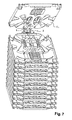
- La figure 6 est une vue en perspective d'un ensemble d'empilage de cassettes dans une position à 45°, conforme à l'invention.
- La figure 7 est une vue avant en perspective le même ensemble d'empilage de cassettes équipé d'un plus grand nombre de cassettes dans une position à 45°, conforme à l'invention
- La figure 8 est une vue arrière de la figure 7.
- Figure 1 is a perspective view of a stack assembly according to the invention in a first position at 45 °.
- Figure 2 is a perspective view of a stack assembly according to the invention in a second position at 45 °.
- Figure 3A is a perspective view of a cassette according to the invention.
- Figure 3B is a detail view of Figure 3A.
- Figure 4 is a front view in perspective of several cassettes according to the invention, in a stacking position at 90 °.
- Figure 5 is a detail rear view of Figure 4.
- Figure 6 is a perspective view of a stacking assembly of cassettes in a 45 ° position, according to the invention.
- FIG. 7 is a front view in perspective of the same cassette stacking assembly equipped with a larger number of cassettes in a 45 ° position, according to the invention.
- Figure 8 is a rear view of Figure 7.
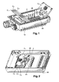
Les figures 1 et 2 illustrent deux positionnements d'un ensemble d'empilage de cassettes optiques en matière plastique, conforme à l'invention, dans un boîtier 1.FIGS. 1 and 2 illustrate two positions of a stacking assembly of plastic optical cassettes according to the invention in a
Cet ensemble d'empilage comporte un rail de support 2 qui est fixé sur une paroi fixe qui est ici le fond du boîtier. Ce rail support comporte deux branches dont une branche dite d'articulation présente deux brides 2A et 2B sur lesquelles sont articulées une pluralité de cassettes Ci. Les cassettes sont empilées à 45°.This stacking assembly comprises a
Selon le positionnement représenté sur la figure 1, la branche d'articulation est fixée sur le fond du boîtier et les cassettes sont dans une position d'empilage dite horizontale.According to the positioning shown in Figure 1, the hinge arm is fixed on the bottom of the housing and the cassettes are in a so-called horizontal stacking position.
Selon le positionnement représenté sur la figure 2, la branche d'articulation est fixée de façon inclinée à 45° par rapport au fond du boîtier et les cassettes sont dans une position d'empilage dite verticale.According to the positioning shown in Figure 2, the hinge arm is fixed inclined at 45 ° relative to the bottom of the housing and the cassettes are in a so-called vertical stacking position.
Par des moyens qui seront décrits plus loin, l'invention permet de réaliser ces deux positionnements avec le même ensemble d'empilage standard, selon l'encombrement disponible et l'agencement du boîtier 1.By means which will be described later, the invention makes it possible to realize these two positions with the same standard stacking assembly, according to the available space and the arrangement of the
Les figures 3A et 3B représentent une cassette de lovage et de raccordement de fibres optiques conforme à l'invention.FIGS. 3A and 3B show a cassette for coiling and connecting optical fibers according to the invention.
Cette cassette C permet un empilage à 45° au moyen du rail de support 2 destiné à être fixé sur une paroi fixe, et comporte un agencement d'articulation avec le rail, cet agencement étant intégré à la cassette.This cassette C allows stacking at 45 ° by means of the
Comme il a été déjà vu, le rail de support 2 comporte deux brides présentant des paires d'orifices destinés chacune à l'articulation d'une cassette et l'agencement d'articulation de la cassette avec le rail est un agencement d'encliquetage.As already seen, the
Cet agencement d'articulation comprend deux pions d'encliquetage 3A et 3B disposés sur un bord de la cassette et moulés dans le corps de la cassette. Grâce à un biseau, chacun de ces pions peut être encliqueté à force dans chaque orifice de la paire d'orifices portée par le rail 2.This articulation arrangement comprises two latching
Selon une autre caractéristique de l'invention, la cassette comporte également un agencement d'articulation entre deux cassettes empilées à 90°, cet agencement étant intégré à la cassette.According to another characteristic of the invention, the cassette also comprises an articulation arrangement between two cassettes stacked at 90 °, this arrangement being integrated in the cassette.
Cet agencement d'articulation comprend deux pions d'encliquetage disposés sur un bord de la cassette et sur chaque face de cette dernière. Une des faces comporte deux pions d'encliquetage mâle 4A et 4B et l'autre face deux pions d'encliquetage femelle 4C et 4D correspondants.This articulation arrangement comprises two detent pins disposed on an edge of the cassette and on each face thereof. One of the faces comprises two male latching pins 4A and 4B and the other side two female latching pins 4C and 4D corresponding.
La cassette comporte également un agencement de verrouillage en position ouverte, où deux cassettes initialement empilées à 90° sont déplacées au moyen des pions d'encliquetage 4 dans une position perpendiculaire l'une à l'autre.The cassette also has a locking arrangement in the open position, where two cassettes initially stacked at 90 ° are moved by means of the detent pins 4 in a position perpendicular to each other.
Cet agencement de verrouillage en position ouverte comprend une bride 5 disposée sur le même bord de la cassette entre les deux pions d'encliquetage, formant un cliquet et comportant sur une de ses faces une rainure 5A correspondante à ce cliquet.This locking arrangement in the open position comprises a
Cet agencement d'articulation ainsi que cet agencement de verrouillage sont moulés dans le corps de la cassette.This hinge arrangement and this locking arrangement are molded into the body of the cassette.
Les figures 4 et 5 illustrent un empilage à 90° de trois cassettes Ci, conforme à l'invention, avec deux cassettes C2 et C3 en position ouverte.Figures 4 and 5 illustrate a stack of 90 ° three cassettes Ci, according to the invention, with two cassettes C2 and C3 in the open position.
Les cassettes sont ici articulées l'une à l'autre grâce à l'encliquetage mutuel de leurs pions d'encliquetage 4.The cassettes are here articulated to one another by virtue of the mutual snapping of their detent pins 4.
Plus précisément, comme bien visible sur la figure 5, les deux pions d'encliquetage femelle 4C1 et 4D1 de la première cassette C1 sont encliquetés dans les deux pions d'encliquetage mâle 4A2 et 4B2 de la deuxième cassette C2 et les deux pions d'encliquetage femelle 4C2 et 4D2 de la deuxième cassette C2 sont encliquetés dans les deux pions d'encliquetage mâle 4A3 et 4B3 de la troisième cassette C3.More precisely, as clearly visible in FIG. 5, the two female latching pins 4C1 and 4D1 of the first cassette C1 are snapped into the two male latching pins 4A2 and 4B2 of the second cassette C2 and the two pins of FIG. female clipping 4C2 and 4D2 of the second cassette C2 are snapped into the two male detent pins 4A3 and 4B3 of the third cassette C3.
Le verrouillage en position ouverte de la deuxième cassette C2 est réalisé par coopération des brides de verrouillage des première et deuxième cassettes, comme également visible sur la figure 5.The locking in the open position of the second cassette C2 is achieved by cooperation of the locking flanges of the first and second cassettes, as also visible in FIG.
La bride de verrouillage 51 de la première cassette C1 reçoit dans sa rainure 5A1 la bride 52 formant cliquet de la deuxième cassette C2, en position ouverte.The locking
Le maintien en position de la troisième cassette C3 est alors assurée par un autre agencement de verrouillage qui constitue une caractéristique importante de la cassette conforme à l'invention.The holding in position of the third cassette C3 is then provided by another locking arrangement which is an important feature of the cassette according to the invention.
La cassette conforme à l'invention comporte en effet un agencement de verrouillage par paire de cassettes empilées dans une position d'empilage à 90° ou à 45°, cet agencement étant intégré à la cassette. Cet agencement est visible sur les figures 3A et 4.The cassette according to the invention in fact comprises a lock arrangement pair of stacked cassettes in a stacking position at 90 ° or 45 °, this arrangement being integrated in the cassette. This arrangement is visible in FIGS. 3A and 4.
Cet agencement de verrouillage est constitué de deux brides 6A2 et 6B2 présentant chacune sur une des faces de la cassette un tenon d'encliquetage T1 et T2, visibles sur la deuxième cassette C2, et sur l'autre face de la cassette trois orifices d'encliquetage a à f, visibles sur la première cassette C1, alignés selon un axe de sorte à pouvoir recevoir ledit tenon d'une cassette adjacente dans une position d'empilage à 90° ainsi que dans une position d'empilage incliné, dont un orifice central b et e est disposé au droit du tenon T1 ou T2.This locking arrangement consists of two flanges 6A2 and 6B2 each having on one side of the cassette a snap-fastener T1 and T2, visible on the second cassette C2, and on the other side of the cassette three orifices of snap-fastening a to f, visible on the first cassette C1, aligned along an axis so as to be able to receive said tenon of an adjacent cassette in a stacking position at 90 ° as well as in an inclined stacking position, including an orifice central b and e is arranged at the right of the post T1 or T2.
La distance entre l'orifice central et les deux autres orifices est sensiblement égale à la tangente de l'angle correspondant à l'angle d'inclinaison multiplié par l'épaisseur de la cassette.The distance between the central orifice and the two other orifices is substantially equal to the tangent of the angle corresponding to the angle of inclination multiplied by the thickness of the cassette.
Dans l'exemple décrit, l'angle d'inclinaison est de 45° et la distance entre l'orifice central b et e et les deux autres orifices est sensiblement égale à l'épaisseur de la cassette.In the example described, the angle of inclination is 45 ° and the distance between the central orifice b and e and the other two orifices is substantially equal to the thickness of the cassette.
En d'autres termes, lorsque deux cassettes sont empilées à 90°, les deux tenons de l'une viennent s'encliqueter dans les orifices centraux de l'autre. Lorsque deux cassettes sont empilées à 45°, les tenons de l'une viennent dans une paire des autres orifices. Selon le sens de l'empilage à 45°, il s'agit de la paire c et f la plus proche de l'articulation ou de la paire a et d la plus éloignée de l'articulation.In other words, when two cassettes are stacked at 90 °, the two studs of one are snapped into the central holes of the other. When two cassettes are stacked at 45 °, the tenons of one come in a pair of the other orifices. Depending on the direction of 45 ° stacking, it is the pair c and f closest to the joint or pair a and d farthest from the joint.
Ces deux brides 6A et 6B sont moulées dans le corps de la cassette.These two
Bien qu'illustré dans le cas d'une cassette permettant un empilage à 90° et à 45°, cet agencement de verrouillage par paire de cassette peut être conçu pour des cassettes destinées à être empilées à 90° et sous un angle d'inclinaison autre que 45°.Although illustrated in the case of a cassette for stacking at 90 ° and 45 °, this cassette pair locking arrangement may be designed for cassettes to be stacked at 90 ° and at an angle of inclination. other than 45 °.
L'invention concerne également un rail de support 2 et un ensemble d'empilage constitué de ce rail et de cassettes conformes à l'invention, qui permet un empilage incliné, de préférence à 45°. Cet ensemble d'empilage est représenté sur les figures 6 à 8.The invention also relates to a
Ce rail 2 comporte deux branches 2C et 2D inclinées l'une par rapport à l'autre, dont l'une 2C est pourvue de deux brides 2A et 2B présentant des paires d'orifices O destinés chacune à l'articulation d'une cassette. Ces deux branches 2C et 2D sont pourvues de moyen de fixation à une paroi fixe, de préférence des alésages AC et AD permettant leur vissage.This
Cette caractéristique permet de fixer ce rail selon la position représentée sur la figure 1, par fixation de la branche 2C portant les moyens d'articulation de cassettes sur le fond d'un boîtier 1, ou dans la position représentée sur la figure 2, par fixation de l'autre branche 2D sur le fond d'un boîtier 1.This characteristic makes it possible to fix this rail according to the position represented in FIG. 1, by fixing the
Avantageusement, la branche 2C portant les moyens d'articulation de cassettes présente des lignes sécables S qui permettent aisément de régler sa longueur selon le nombre de cassettes.Advantageously, the
A proximité de chacune de ces lignes sécables S, est agencée une patte P faisant saillie en direction des cassettes et qui est destinée au verrouillage en position ouverte de la première cassette C1 de l'empilage, telle que représenté sur les figures 6 à 8.Near each of these breakable lines S is arranged a tab P projecting towards the cassettes and which is intended for locking in the open position of the first cassette C1 of the stack, as shown in FIGS. 6 to 8.
Pour ce verrouillage, la cassette conforme à l'invention comporte un agencement de verrouillage en position ouverte, coopérant avec cette patte P réalisé sur le rail 2. Cet agencement de verrouillage en position ouverte est constitué d'un cliquet moulé dans le corps de la cassette et coopérant avec la patte P agencée sur le rail. Ce cliquet est très avantageusement le cliquet formé par la bride de verrouillage en position ouverte 5 déjà décrite.For this locking, the cassette according to the invention comprises a locking arrangement in the open position, cooperating with this tab P made on the
Grâce à l'invention, il est réalisé une cassette optique standard, qui peut être empilée en un empilage à 90° ou en un empilage incliné vertical ou horizontal, de préférence à 45°, associée à un rail support, et ceci, sans nécessité de pièces détachées supplémentaires, tous les agencements d'articulation et de verrouillage étant intégrés à la cassette et, de préférence, moulés avec le corps de celle-ci.Thanks to the invention, it is realized a standard optical cassette, which can be stacked in a stack at 90 ° or in a vertical or horizontal inclined stack, preferably at 45 °, associated with a support rail, and this, without need additional spare parts, all articulation and locking arrangements being integrated with the cassette and, preferably, molded with the body thereof.
Claims (21)
Applications Claiming Priority (1)
| Application Number | Priority Date | Filing Date | Title |
|---|---|---|---|
| FR0652609A FR2902897B1 (en) | 2006-06-22 | 2006-06-22 | CASSETTE FOR OPTICAL CABLES, SUPPORT RAIL AND STACKING ASSEMBLY OF SUCH CASSETTES |
Publications (3)
| Publication Number | Publication Date |
|---|---|
| EP1870750A2 true EP1870750A2 (en) | 2007-12-26 |
| EP1870750A3 EP1870750A3 (en) | 2008-01-02 |
| EP1870750B1 EP1870750B1 (en) | 2010-06-16 |
Family
ID=37708311
Family Applications (1)
| Application Number | Title | Priority Date | Filing Date |
|---|---|---|---|
| EP07301127A Not-in-force EP1870750B1 (en) | 2006-06-22 | 2007-06-19 | Cassette for optical cables, support rail and assembly for stacking such cassettes |
Country Status (6)
| Country | Link |
|---|---|
| EP (1) | EP1870750B1 (en) |
| AT (1) | ATE471526T1 (en) |
| DE (1) | DE602007007155D1 (en) |
| ES (1) | ES2347707T3 (en) |
| FR (1) | FR2902897B1 (en) |
| PT (1) | PT1870750E (en) |
Cited By (10)
| Publication number | Priority date | Publication date | Assignee | Title |
|---|---|---|---|---|
| WO2009089327A2 (en) * | 2008-01-09 | 2009-07-16 | Adc Telecommunications, Inc. | Wall box adapted to be mounted at a mid-span access location of a telecommunications cable |
| US7751675B2 (en) | 2007-12-11 | 2010-07-06 | Adc Telecommunications, Inc. | Wall box adapted to be mounted at a mid-span access location of a telecommunications cable |
| WO2011091824A1 (en) * | 2010-02-01 | 2011-08-04 | Adc Gmbh | Distribution cabinet for optical fibre cables |
| EP2463696A1 (en) | 2010-12-07 | 2012-06-13 | Nexans | Cassette for coiling fibres and maintaining splices |
| US8213760B2 (en) | 2009-01-28 | 2012-07-03 | Adc Telecommunications, Inc. | Fiber optic enclosure |
| ITMI20111136A1 (en) * | 2011-06-22 | 2012-12-23 | Prysmian Spa | TRAY FOR FIBER OPTICS |
| WO2013075966A1 (en) * | 2011-11-22 | 2013-05-30 | Tyco Electronics Raychem Bvba | Fiber tray organizer systems and methods |
| WO2015067003A1 (en) * | 2013-11-05 | 2015-05-14 | 华为技术有限公司 | Optical fibre jumper device, port panel and optical fibre jumper system |
| FR3013127A1 (en) * | 2013-11-08 | 2015-05-15 | Decelect | FIBER OPTIC CABLES CONNECTION CASSETTE |
| EP3239752A1 (en) * | 2016-04-28 | 2017-11-01 | Reichle & De-Massari AG | Cable management device and method with a cable management device |
Citations (10)
| Publication number | Priority date | Publication date | Assignee | Title |
|---|---|---|---|---|
| WO1989005989A1 (en) * | 1987-12-23 | 1989-06-29 | British Telecommunications Public Limited Company | Mounting assembly for optical equipment |
| EP0557187A1 (en) * | 1992-02-21 | 1993-08-25 | Alcatel Cable Interface | Assembly of flat articulated modules |
| EP0557190A1 (en) * | 1992-02-21 | 1993-08-25 | Alcatel Cable Interface | Assembly of stacked articulated modules |
| WO1994012904A2 (en) * | 1992-11-25 | 1994-06-09 | Raychem Corporation | Fiber optic splice closure |
| US5553186A (en) * | 1995-03-31 | 1996-09-03 | Minnesota Mining And Manufacturing Company | Fiber optic dome closure |
| GB2316496A (en) * | 1996-08-09 | 1998-02-25 | Bowthorpe Plc | Hinged optical fibre storage enclosure |
| FR2793564A1 (en) * | 1999-05-11 | 2000-11-17 | Rxs Morel Accessoires De Cable | STACK OF CASSETTES THAT CAN OPEN FROM TWO SIDES |
| DE29921304U1 (en) * | 1999-09-07 | 2001-01-18 | Felten & Guilleaume Ag Oester | Stack arrangement for releasable connection of splice cassettes |
| EP1593994A2 (en) * | 2004-05-06 | 2005-11-09 | Commscope Solutions Properties, LLC | Carrier for multiple splice trays |
| EP1832907A1 (en) * | 2006-03-10 | 2007-09-12 | Ictl | Wired element coiling box assembly |
-
2006
- 2006-06-22 FR FR0652609A patent/FR2902897B1/en not_active Expired - Fee Related
-
2007
- 2007-06-19 AT AT07301127T patent/ATE471526T1/en not_active IP Right Cessation
- 2007-06-19 PT PT07301127T patent/PT1870750E/en unknown
- 2007-06-19 EP EP07301127A patent/EP1870750B1/en not_active Not-in-force
- 2007-06-19 ES ES07301127T patent/ES2347707T3/en active Active
- 2007-06-19 DE DE602007007155T patent/DE602007007155D1/en active Active
Patent Citations (10)
| Publication number | Priority date | Publication date | Assignee | Title |
|---|---|---|---|---|
| WO1989005989A1 (en) * | 1987-12-23 | 1989-06-29 | British Telecommunications Public Limited Company | Mounting assembly for optical equipment |
| EP0557187A1 (en) * | 1992-02-21 | 1993-08-25 | Alcatel Cable Interface | Assembly of flat articulated modules |
| EP0557190A1 (en) * | 1992-02-21 | 1993-08-25 | Alcatel Cable Interface | Assembly of stacked articulated modules |
| WO1994012904A2 (en) * | 1992-11-25 | 1994-06-09 | Raychem Corporation | Fiber optic splice closure |
| US5553186A (en) * | 1995-03-31 | 1996-09-03 | Minnesota Mining And Manufacturing Company | Fiber optic dome closure |
| GB2316496A (en) * | 1996-08-09 | 1998-02-25 | Bowthorpe Plc | Hinged optical fibre storage enclosure |
| FR2793564A1 (en) * | 1999-05-11 | 2000-11-17 | Rxs Morel Accessoires De Cable | STACK OF CASSETTES THAT CAN OPEN FROM TWO SIDES |
| DE29921304U1 (en) * | 1999-09-07 | 2001-01-18 | Felten & Guilleaume Ag Oester | Stack arrangement for releasable connection of splice cassettes |
| EP1593994A2 (en) * | 2004-05-06 | 2005-11-09 | Commscope Solutions Properties, LLC | Carrier for multiple splice trays |
| EP1832907A1 (en) * | 2006-03-10 | 2007-09-12 | Ictl | Wired element coiling box assembly |
Cited By (23)
| Publication number | Priority date | Publication date | Assignee | Title |
|---|---|---|---|---|
| US7751675B2 (en) | 2007-12-11 | 2010-07-06 | Adc Telecommunications, Inc. | Wall box adapted to be mounted at a mid-span access location of a telecommunications cable |
| US9557504B2 (en) | 2008-01-09 | 2017-01-31 | Commscope Technologies Llc | Wall box adapted to be mounted at a mid-span access location of a telecommunications cable |
| WO2009089327A3 (en) * | 2008-01-09 | 2009-08-27 | Adc Telecommunications, Inc. | Wall box adapted to be mounted at a mid-span access location of a telecommunications cable |
| US8111966B2 (en) | 2008-01-09 | 2012-02-07 | Adc Telecommunications, Inc. | Wall box adapted to be mounted at a mid-span access location of a telecommunications cable |
| WO2009089327A2 (en) * | 2008-01-09 | 2009-07-16 | Adc Telecommunications, Inc. | Wall box adapted to be mounted at a mid-span access location of a telecommunications cable |
| US11592636B2 (en) | 2008-01-09 | 2023-02-28 | Commscope Technologies Llc | Wall box adapted to be mounted at a mid-span access location of a telecommunications cable |
| US11036018B2 (en) | 2008-01-09 | 2021-06-15 | Commscope Technologies Llc | Wall box adapted to be mounted at a mid-span access location of a telecommunications cable |
| US10422970B2 (en) | 2008-01-09 | 2019-09-24 | Commscope Technologies Llc | Wall box adapted to be mounted at a mid-span access location of a telecommunications cable |
| US8837894B2 (en) | 2008-01-09 | 2014-09-16 | Adc Telecommunications, Inc. | Wall box adapted to be mounted at a mid-span access location of a telecommunications cable |
| US8213760B2 (en) | 2009-01-28 | 2012-07-03 | Adc Telecommunications, Inc. | Fiber optic enclosure |
| WO2011091824A1 (en) * | 2010-02-01 | 2011-08-04 | Adc Gmbh | Distribution cabinet for optical fibre cables |
| US8921693B2 (en) | 2010-02-01 | 2014-12-30 | Tyco Electronics Services Gmbh | Distribution cabinet for optical fibre cables |
| EP2463696A1 (en) | 2010-12-07 | 2012-06-13 | Nexans | Cassette for coiling fibres and maintaining splices |
| AU2012203575B2 (en) * | 2011-06-22 | 2016-11-03 | Prysmian S.P.A. | Tray for optical fibres |
| EP2538257A1 (en) | 2011-06-22 | 2012-12-26 | Prysmian S.p.A. | Tray for optical fibres |
| ITMI20111136A1 (en) * | 2011-06-22 | 2012-12-23 | Prysmian Spa | TRAY FOR FIBER OPTICS |
| US9857547B2 (en) | 2011-11-22 | 2018-01-02 | CommScope Connectivity Belgium BVBA | Fiber tray organizer systems and methods |
| WO2013075966A1 (en) * | 2011-11-22 | 2013-05-30 | Tyco Electronics Raychem Bvba | Fiber tray organizer systems and methods |
| US9535220B2 (en) | 2013-11-05 | 2017-01-03 | Huawei Technologies Co., Ltd. | Fiber patch cord apparatus, port panel, and fiber patch cord system |
| WO2015067003A1 (en) * | 2013-11-05 | 2015-05-14 | 华为技术有限公司 | Optical fibre jumper device, port panel and optical fibre jumper system |
| FR3013127A1 (en) * | 2013-11-08 | 2015-05-15 | Decelect | FIBER OPTIC CABLES CONNECTION CASSETTE |
| EP3239752A1 (en) * | 2016-04-28 | 2017-11-01 | Reichle & De-Massari AG | Cable management device and method with a cable management device |
| DE102016107915A1 (en) * | 2016-04-28 | 2017-11-02 | Reichle & De-Massari Ag | Cable management device and method with a cable management device |
Also Published As
| Publication number | Publication date |
|---|---|
| EP1870750A3 (en) | 2008-01-02 |
| PT1870750E (en) | 2010-09-16 |
| FR2902897B1 (en) | 2008-12-26 |
| FR2902897A1 (en) | 2007-12-28 |
| ES2347707T3 (en) | 2010-11-03 |
| EP1870750B1 (en) | 2010-06-16 |
| ATE471526T1 (en) | 2010-07-15 |
| DE602007007155D1 (en) | 2010-07-29 |
Similar Documents
| Publication | Publication Date | Title |
|---|---|---|
| EP1870750B1 (en) | Cassette for optical cables, support rail and assembly for stacking such cassettes | |
| FR2687743A1 (en) | SET OF STACKED AND ARTICULATED MODULES. | |
| FR2773400A1 (en) | METAL CONDUIT SYSTEM CAPABLE OF RECEIVING A FIBER OPTIC CABLE | |
| FR2959383A1 (en) | Cable connection and/or storage device for termination of optical fiber cables of telecommunication network, has hinge fixed with case in fixation positions that correspond to positioning of hinge to fix hinge with posts, respectively | |
| EP2466692B1 (en) | Connector for a printed circuit board | |
| EP2775334B1 (en) | Device comprising a plurality of boxes for connecting and/or storing cable or cable fibre | |
| EP1720395B1 (en) | Ventilatilation device having fixing means with elastic fingers | |
| EP0685915B1 (en) | Suspension device for electrical ducting | |
| FR2917183A1 (en) | CONNECTING HOUSING FOR OPTICAL FIBERS WITH SEALING MEANS. | |
| EP2631692B1 (en) | Device for connecting and/or storing cables and corresponding mounting method | |
| EP4283806A2 (en) | Element for connecting wire-mesh cable-tray sections | |
| EP1094579B1 (en) | Support for mounting at least an electrical apparatus on a cable duct | |
| WO2012052477A1 (en) | System for assembling devices, in particular lighting devices, and corresponding assembly part | |
| FR2957155A1 (en) | Fiber optical network cable and subscriber cord connection device fixing device i.e. soleplate, for e.g. clamping case, has assembling unit permitting assembling and separation of fixation device and support when support is closed | |
| FR2898417A1 (en) | Filaire element e.g. cable`s optic fiber, rotating case, has articulation unit formed on peripheral walls, and including cylindrical finger housed in recess by slight plastic deformation to form articulation between case and adjacent case | |
| EP2958195A1 (en) | Modular device for communication box | |
| EP3503699B1 (en) | Interconnection system for electronic cards and computer calculation cabinet comprising such a system | |
| EP2755071B1 (en) | Optical connection module | |
| FR3013127A1 (en) | FIBER OPTIC CABLES CONNECTION CASSETTE | |
| EP1583192B1 (en) | Electric cabinet with cable feedthroughs | |
| EP2113799A1 (en) | Junction box for the connections of optical fibre cables | |
| EP2388632A1 (en) | Box for connecting optical fibres | |
| FR2853150A1 (en) | Closing device for raceway of electrical cable housing, has connecting section of covering part enabling movement of secondary fixing units on device to take different functioning positions for coupling with primary fixing units | |
| EP4109694A1 (en) | Bar for organising cables into a layer, assembly for organising cables comprising such bars, and method for assembling such an assembly for organisation | |
| FR3001045A1 (en) | Parallelepiped optical connection module for use in modular optical connection device in e.g. fiber to home network, has connectors arranged on vertical wall parallel to alignment direction of zones, so that user directly access connectors |
Legal Events
| Date | Code | Title | Description |
|---|---|---|---|
| PUAI | Public reference made under article 153(3) epc to a published international application that has entered the european phase |
Free format text: ORIGINAL CODE: 0009012 |
|
| PUAL | Search report despatched |
Free format text: ORIGINAL CODE: 0009013 |
|
| AK | Designated contracting states |
Kind code of ref document: A2 Designated state(s): AT BE BG CH CY CZ DE DK EE ES FI FR GB GR HU IE IS IT LI LT LU LV MC MT NL PL PT RO SE SI SK TR |
|
| AX | Request for extension of the european patent |
Extension state: AL BA HR MK YU |
|
| AK | Designated contracting states |
Kind code of ref document: A3 Designated state(s): AT BE BG CH CY CZ DE DK EE ES FI FR GB GR HU IE IS IT LI LT LU LV MC MT NL PL PT RO SE SI SK TR |
|
| AX | Request for extension of the european patent |
Extension state: AL BA HR MK YU |
|
| 17P | Request for examination filed |
Effective date: 20080702 |
|
| 17Q | First examination report despatched |
Effective date: 20080804 |
|
| AKX | Designation fees paid |
Designated state(s): AT BE BG CH CY CZ DE DK EE ES FI FR GB GR HU IE IS IT LI LT LU LV MC MT NL PL PT RO SE SI SK TR |
|
| GRAP | Despatch of communication of intention to grant a patent |
Free format text: ORIGINAL CODE: EPIDOSNIGR1 |
|
| GRAS | Grant fee paid |
Free format text: ORIGINAL CODE: EPIDOSNIGR3 |
|
| GRAA | (expected) grant |
Free format text: ORIGINAL CODE: 0009210 |
|
| AK | Designated contracting states |
Kind code of ref document: B1 Designated state(s): AT BE BG CH CY CZ DE DK EE ES FI FR GB GR HU IE IS IT LI LT LU LV MC MT NL PL PT RO SE SI SK TR |
|
| REG | Reference to a national code |
Ref country code: CH Ref legal event code: EP |
|
| REG | Reference to a national code |
Ref country code: IE Ref legal event code: FG4D Free format text: LANGUAGE OF EP DOCUMENT: FRENCH |
|
| REF | Corresponds to: |
Ref document number: 602007007155 Country of ref document: DE Date of ref document: 20100729 Kind code of ref document: P |
|
| REG | Reference to a national code |
Ref country code: PT Ref legal event code: SC4A Free format text: AVAILABILITY OF NATIONAL TRANSLATION Effective date: 20100909 |
|
| REG | Reference to a national code |
Ref country code: SE Ref legal event code: TRGR |
|
| REG | Reference to a national code |
Ref country code: NL Ref legal event code: VDEP Effective date: 20100616 |
|
| PG25 | Lapsed in a contracting state [announced via postgrant information from national office to epo] |
Ref country code: LT Free format text: LAPSE BECAUSE OF FAILURE TO SUBMIT A TRANSLATION OF THE DESCRIPTION OR TO PAY THE FEE WITHIN THE PRESCRIBED TIME-LIMIT Effective date: 20100616 |
|
| REG | Reference to a national code |
Ref country code: ES Ref legal event code: FG2A Ref document number: 2347707 Country of ref document: ES Kind code of ref document: T3 |
|
| LTIE | Lt: invalidation of european patent or patent extension |
Effective date: 20100616 |
|
| PG25 | Lapsed in a contracting state [announced via postgrant information from national office to epo] |
Ref country code: SI Free format text: LAPSE BECAUSE OF FAILURE TO SUBMIT A TRANSLATION OF THE DESCRIPTION OR TO PAY THE FEE WITHIN THE PRESCRIBED TIME-LIMIT Effective date: 20100616 Ref country code: LV Free format text: LAPSE BECAUSE OF FAILURE TO SUBMIT A TRANSLATION OF THE DESCRIPTION OR TO PAY THE FEE WITHIN THE PRESCRIBED TIME-LIMIT Effective date: 20100616 Ref country code: FI Free format text: LAPSE BECAUSE OF FAILURE TO SUBMIT A TRANSLATION OF THE DESCRIPTION OR TO PAY THE FEE WITHIN THE PRESCRIBED TIME-LIMIT Effective date: 20100616 Ref country code: AT Free format text: LAPSE BECAUSE OF FAILURE TO SUBMIT A TRANSLATION OF THE DESCRIPTION OR TO PAY THE FEE WITHIN THE PRESCRIBED TIME-LIMIT Effective date: 20100616 |
|
| BERE | Be: lapsed |
Owner name: NEXANS Effective date: 20100630 |
|
| PG25 | Lapsed in a contracting state [announced via postgrant information from national office to epo] |
Ref country code: CY Free format text: LAPSE BECAUSE OF FAILURE TO SUBMIT A TRANSLATION OF THE DESCRIPTION OR TO PAY THE FEE WITHIN THE PRESCRIBED TIME-LIMIT Effective date: 20100616 Ref country code: PL Free format text: LAPSE BECAUSE OF FAILURE TO SUBMIT A TRANSLATION OF THE DESCRIPTION OR TO PAY THE FEE WITHIN THE PRESCRIBED TIME-LIMIT Effective date: 20100616 |
|
| REG | Reference to a national code |
Ref country code: IE Ref legal event code: FD4D |
|
| PG25 | Lapsed in a contracting state [announced via postgrant information from national office to epo] |
Ref country code: EE Free format text: LAPSE BECAUSE OF FAILURE TO SUBMIT A TRANSLATION OF THE DESCRIPTION OR TO PAY THE FEE WITHIN THE PRESCRIBED TIME-LIMIT Effective date: 20100616 Ref country code: NL Free format text: LAPSE BECAUSE OF FAILURE TO SUBMIT A TRANSLATION OF THE DESCRIPTION OR TO PAY THE FEE WITHIN THE PRESCRIBED TIME-LIMIT Effective date: 20100616 Ref country code: IE Free format text: LAPSE BECAUSE OF FAILURE TO SUBMIT A TRANSLATION OF THE DESCRIPTION OR TO PAY THE FEE WITHIN THE PRESCRIBED TIME-LIMIT Effective date: 20100616 Ref country code: MC Free format text: LAPSE BECAUSE OF NON-PAYMENT OF DUE FEES Effective date: 20100630 |
|
| PG25 | Lapsed in a contracting state [announced via postgrant information from national office to epo] |
Ref country code: SK Free format text: LAPSE BECAUSE OF FAILURE TO SUBMIT A TRANSLATION OF THE DESCRIPTION OR TO PAY THE FEE WITHIN THE PRESCRIBED TIME-LIMIT Effective date: 20100616 Ref country code: RO Free format text: LAPSE BECAUSE OF FAILURE TO SUBMIT A TRANSLATION OF THE DESCRIPTION OR TO PAY THE FEE WITHIN THE PRESCRIBED TIME-LIMIT Effective date: 20100616 Ref country code: IS Free format text: LAPSE BECAUSE OF FAILURE TO SUBMIT A TRANSLATION OF THE DESCRIPTION OR TO PAY THE FEE WITHIN THE PRESCRIBED TIME-LIMIT Effective date: 20101016 Ref country code: CZ Free format text: LAPSE BECAUSE OF FAILURE TO SUBMIT A TRANSLATION OF THE DESCRIPTION OR TO PAY THE FEE WITHIN THE PRESCRIBED TIME-LIMIT Effective date: 20100616 |
|
| RAP2 | Party data changed (patent owner data changed or rights of a patent transferred) |
Owner name: NEXANS |
|
| PG25 | Lapsed in a contracting state [announced via postgrant information from national office to epo] |
Ref country code: IT Free format text: LAPSE BECAUSE OF NON-PAYMENT OF DUE FEES Effective date: 20100619 |
|
| PLBE | No opposition filed within time limit |
Free format text: ORIGINAL CODE: 0009261 |
|
| STAA | Information on the status of an ep patent application or granted ep patent |
Free format text: STATUS: NO OPPOSITION FILED WITHIN TIME LIMIT |
|
| PG25 | Lapsed in a contracting state [announced via postgrant information from national office to epo] |
Ref country code: DK Free format text: LAPSE BECAUSE OF FAILURE TO SUBMIT A TRANSLATION OF THE DESCRIPTION OR TO PAY THE FEE WITHIN THE PRESCRIBED TIME-LIMIT Effective date: 20100616 Ref country code: GR Free format text: LAPSE BECAUSE OF FAILURE TO SUBMIT A TRANSLATION OF THE DESCRIPTION OR TO PAY THE FEE WITHIN THE PRESCRIBED TIME-LIMIT Effective date: 20100917 Ref country code: MT Free format text: LAPSE BECAUSE OF FAILURE TO SUBMIT A TRANSLATION OF THE DESCRIPTION OR TO PAY THE FEE WITHIN THE PRESCRIBED TIME-LIMIT Effective date: 20100616 |
|
| 26N | No opposition filed |
Effective date: 20110317 |
|
| PG25 | Lapsed in a contracting state [announced via postgrant information from national office to epo] |
Ref country code: BE Free format text: LAPSE BECAUSE OF NON-PAYMENT OF DUE FEES Effective date: 20100630 |
|
| REG | Reference to a national code |
Ref country code: DE Ref legal event code: R097 Ref document number: 602007007155 Country of ref document: DE Effective date: 20110316 |
|
| REG | Reference to a national code |
Ref country code: CH Ref legal event code: PL |
|
| PG25 | Lapsed in a contracting state [announced via postgrant information from national office to epo] |
Ref country code: CH Free format text: LAPSE BECAUSE OF NON-PAYMENT OF DUE FEES Effective date: 20110630 Ref country code: LI Free format text: LAPSE BECAUSE OF NON-PAYMENT OF DUE FEES Effective date: 20110630 |
|
| PGFP | Annual fee paid to national office [announced via postgrant information from national office to epo] |
Ref country code: DE Payment date: 20120622 Year of fee payment: 6 |
|
| PGFP | Annual fee paid to national office [announced via postgrant information from national office to epo] |
Ref country code: GB Payment date: 20120622 Year of fee payment: 6 |
|
| PG25 | Lapsed in a contracting state [announced via postgrant information from national office to epo] |
Ref country code: HU Free format text: LAPSE BECAUSE OF FAILURE TO SUBMIT A TRANSLATION OF THE DESCRIPTION OR TO PAY THE FEE WITHIN THE PRESCRIBED TIME-LIMIT Effective date: 20101217 Ref country code: LU Free format text: LAPSE BECAUSE OF NON-PAYMENT OF DUE FEES Effective date: 20100619 Ref country code: BG Free format text: LAPSE BECAUSE OF FAILURE TO SUBMIT A TRANSLATION OF THE DESCRIPTION OR TO PAY THE FEE WITHIN THE PRESCRIBED TIME-LIMIT Effective date: 20100616 |
|
| PG25 | Lapsed in a contracting state [announced via postgrant information from national office to epo] |
Ref country code: TR Free format text: LAPSE BECAUSE OF FAILURE TO SUBMIT A TRANSLATION OF THE DESCRIPTION OR TO PAY THE FEE WITHIN THE PRESCRIBED TIME-LIMIT Effective date: 20100616 |
|
| PGFP | Annual fee paid to national office [announced via postgrant information from national office to epo] |
Ref country code: ES Payment date: 20120627 Year of fee payment: 6 |
|
| PGFP | Annual fee paid to national office [announced via postgrant information from national office to epo] |
Ref country code: PT Payment date: 20111219 Year of fee payment: 6 |
|
| PG25 | Lapsed in a contracting state [announced via postgrant information from national office to epo] |
Ref country code: BG Free format text: LAPSE BECAUSE OF FAILURE TO SUBMIT A TRANSLATION OF THE DESCRIPTION OR TO PAY THE FEE WITHIN THE PRESCRIBED TIME-LIMIT Effective date: 20100916 |
|
| REG | Reference to a national code |
Ref country code: PT Ref legal event code: MM4A Free format text: LAPSE DUE TO NON-PAYMENT OF FEES Effective date: 20131219 |
|
| PG25 | Lapsed in a contracting state [announced via postgrant information from national office to epo] |
Ref country code: PT Free format text: LAPSE BECAUSE OF NON-PAYMENT OF DUE FEES Effective date: 20131219 |
|
| GBPC | Gb: european patent ceased through non-payment of renewal fee |
Effective date: 20130619 |
|
| REG | Reference to a national code |
Ref country code: DE Ref legal event code: R119 Ref document number: 602007007155 Country of ref document: DE Effective date: 20140101 |
|
| PG25 | Lapsed in a contracting state [announced via postgrant information from national office to epo] |
Ref country code: DE Free format text: LAPSE BECAUSE OF NON-PAYMENT OF DUE FEES Effective date: 20140101 Ref country code: GB Free format text: LAPSE BECAUSE OF NON-PAYMENT OF DUE FEES Effective date: 20130619 |
|
| REG | Reference to a national code |
Ref country code: ES Ref legal event code: FD2A Effective date: 20140707 |
|
| PGFP | Annual fee paid to national office [announced via postgrant information from national office to epo] |
Ref country code: SE Payment date: 20140618 Year of fee payment: 8 |
|
| PG25 | Lapsed in a contracting state [announced via postgrant information from national office to epo] |
Ref country code: ES Free format text: LAPSE BECAUSE OF NON-PAYMENT OF DUE FEES Effective date: 20130620 |
|
| PGFP | Annual fee paid to national office [announced via postgrant information from national office to epo] |
Ref country code: FR Payment date: 20140619 Year of fee payment: 8 |
|
| PGFP | Annual fee paid to national office [announced via postgrant information from national office to epo] |
Ref country code: IT Payment date: 20140630 Year of fee payment: 8 |
|
| PG25 | Lapsed in a contracting state [announced via postgrant information from national office to epo] |
Ref country code: IT Free format text: LAPSE BECAUSE OF NON-PAYMENT OF DUE FEES Effective date: 20150619 |
|
| REG | Reference to a national code |
Ref country code: SE Ref legal event code: EUG |
|
| PG25 | Lapsed in a contracting state [announced via postgrant information from national office to epo] |
Ref country code: SE Free format text: LAPSE BECAUSE OF NON-PAYMENT OF DUE FEES Effective date: 20150620 |
|
| REG | Reference to a national code |
Ref country code: FR Ref legal event code: ST Effective date: 20160229 |
|
| PG25 | Lapsed in a contracting state [announced via postgrant information from national office to epo] |
Ref country code: FR Free format text: LAPSE BECAUSE OF NON-PAYMENT OF DUE FEES Effective date: 20150630 |