EP1870620A1 - On-off valve device for fluid - Google Patents
On-off valve device for fluid Download PDFInfo
- Publication number
- EP1870620A1 EP1870620A1 EP06732116A EP06732116A EP1870620A1 EP 1870620 A1 EP1870620 A1 EP 1870620A1 EP 06732116 A EP06732116 A EP 06732116A EP 06732116 A EP06732116 A EP 06732116A EP 1870620 A1 EP1870620 A1 EP 1870620A1
- Authority
- EP
- European Patent Office
- Prior art keywords
- valve
- seal portion
- fluid
- pressure
- valve seat
- Prior art date
- Legal status (The legal status is an assumption and is not a legal conclusion. Google has not performed a legal analysis and makes no representation as to the accuracy of the status listed.)
- Granted
Links
Images







Classifications
-
- F—MECHANICAL ENGINEERING; LIGHTING; HEATING; WEAPONS; BLASTING
- F16—ENGINEERING ELEMENTS AND UNITS; GENERAL MEASURES FOR PRODUCING AND MAINTAINING EFFECTIVE FUNCTIONING OF MACHINES OR INSTALLATIONS; THERMAL INSULATION IN GENERAL
- F16K—VALVES; TAPS; COCKS; ACTUATING-FLOATS; DEVICES FOR VENTING OR AERATING
- F16K25/00—Details relating to contact between valve members and seats
- F16K25/005—Particular materials for seats or closure elements
-
- F—MECHANICAL ENGINEERING; LIGHTING; HEATING; WEAPONS; BLASTING
- F16—ENGINEERING ELEMENTS AND UNITS; GENERAL MEASURES FOR PRODUCING AND MAINTAINING EFFECTIVE FUNCTIONING OF MACHINES OR INSTALLATIONS; THERMAL INSULATION IN GENERAL
- F16J—PISTONS; CYLINDERS; SEALINGS
- F16J15/00—Sealings
- F16J15/02—Sealings between relatively-stationary surfaces
- F16J15/06—Sealings between relatively-stationary surfaces with solid packing compressed between sealing surfaces
- F16J15/10—Sealings between relatively-stationary surfaces with solid packing compressed between sealing surfaces with non-metallic packing
- F16J15/104—Sealings between relatively-stationary surfaces with solid packing compressed between sealing surfaces with non-metallic packing characterised by structure
-
- F—MECHANICAL ENGINEERING; LIGHTING; HEATING; WEAPONS; BLASTING
- F16—ENGINEERING ELEMENTS AND UNITS; GENERAL MEASURES FOR PRODUCING AND MAINTAINING EFFECTIVE FUNCTIONING OF MACHINES OR INSTALLATIONS; THERMAL INSULATION IN GENERAL
- F16J—PISTONS; CYLINDERS; SEALINGS
- F16J15/00—Sealings
- F16J15/46—Sealings with packing ring expanded or pressed into place by fluid pressure, e.g. inflatable packings
- F16J15/48—Sealings with packing ring expanded or pressed into place by fluid pressure, e.g. inflatable packings influenced by the pressure within the member to be sealed
-
- F—MECHANICAL ENGINEERING; LIGHTING; HEATING; WEAPONS; BLASTING
- F16—ENGINEERING ELEMENTS AND UNITS; GENERAL MEASURES FOR PRODUCING AND MAINTAINING EFFECTIVE FUNCTIONING OF MACHINES OR INSTALLATIONS; THERMAL INSULATION IN GENERAL
- F16K—VALVES; TAPS; COCKS; ACTUATING-FLOATS; DEVICES FOR VENTING OR AERATING
- F16K1/00—Lift valves or globe valves, i.e. cut-off apparatus with closure members having at least a component of their opening and closing motion perpendicular to the closing faces
- F16K1/32—Details
- F16K1/34—Cutting-off parts, e.g. valve members, seats
- F16K1/44—Details of seats or valve members of double-seat valves
-
- F—MECHANICAL ENGINEERING; LIGHTING; HEATING; WEAPONS; BLASTING
- F16—ENGINEERING ELEMENTS AND UNITS; GENERAL MEASURES FOR PRODUCING AND MAINTAINING EFFECTIVE FUNCTIONING OF MACHINES OR INSTALLATIONS; THERMAL INSULATION IN GENERAL
- F16K—VALVES; TAPS; COCKS; ACTUATING-FLOATS; DEVICES FOR VENTING OR AERATING
- F16K15/00—Check valves
-
- F—MECHANICAL ENGINEERING; LIGHTING; HEATING; WEAPONS; BLASTING
- F16—ENGINEERING ELEMENTS AND UNITS; GENERAL MEASURES FOR PRODUCING AND MAINTAINING EFFECTIVE FUNCTIONING OF MACHINES OR INSTALLATIONS; THERMAL INSULATION IN GENERAL
- F16K—VALVES; TAPS; COCKS; ACTUATING-FLOATS; DEVICES FOR VENTING OR AERATING
- F16K15/00—Check valves
- F16K15/02—Check valves with guided rigid valve members
- F16K15/025—Check valves with guided rigid valve members the valve being loaded by a spring
-
- F—MECHANICAL ENGINEERING; LIGHTING; HEATING; WEAPONS; BLASTING
- F16—ENGINEERING ELEMENTS AND UNITS; GENERAL MEASURES FOR PRODUCING AND MAINTAINING EFFECTIVE FUNCTIONING OF MACHINES OR INSTALLATIONS; THERMAL INSULATION IN GENERAL
- F16K—VALVES; TAPS; COCKS; ACTUATING-FLOATS; DEVICES FOR VENTING OR AERATING
- F16K39/00—Devices for relieving the pressure on the sealing faces
- F16K39/02—Devices for relieving the pressure on the sealing faces for lift valves
-
- Y—GENERAL TAGGING OF NEW TECHNOLOGICAL DEVELOPMENTS; GENERAL TAGGING OF CROSS-SECTIONAL TECHNOLOGIES SPANNING OVER SEVERAL SECTIONS OF THE IPC; TECHNICAL SUBJECTS COVERED BY FORMER USPC CROSS-REFERENCE ART COLLECTIONS [XRACs] AND DIGESTS
- Y10—TECHNICAL SUBJECTS COVERED BY FORMER USPC
- Y10T—TECHNICAL SUBJECTS COVERED BY FORMER US CLASSIFICATION
- Y10T137/00—Fluid handling
- Y10T137/7722—Line condition change responsive valves
- Y10T137/7837—Direct response valves [i.e., check valve type]
- Y10T137/7866—Plural seating
- Y10T137/7867—Sequential
- Y10T137/7868—Resilient gasket
-
- Y—GENERAL TAGGING OF NEW TECHNOLOGICAL DEVELOPMENTS; GENERAL TAGGING OF CROSS-SECTIONAL TECHNOLOGIES SPANNING OVER SEVERAL SECTIONS OF THE IPC; TECHNICAL SUBJECTS COVERED BY FORMER USPC CROSS-REFERENCE ART COLLECTIONS [XRACs] AND DIGESTS
- Y10—TECHNICAL SUBJECTS COVERED BY FORMER USPC
- Y10T—TECHNICAL SUBJECTS COVERED BY FORMER US CLASSIFICATION
- Y10T137/00—Fluid handling
- Y10T137/7722—Line condition change responsive valves
- Y10T137/7837—Direct response valves [i.e., check valve type]
- Y10T137/7869—Biased open
Definitions
- the present invention relates to a fluid on-off valve device for opening and closing a fluid passage.
- a sealing method for a valve part for high-pressure fluid in high-pressure on-off valve device for opening and closing a high-pressure fluid passage
- a method of attaching a seal member formed out of any type of rubber, resin and metal onto a valve body as a movable part and locating the seal member on a valve seat portion to seal fluid for example, as disclosed in Japanese Patent Laid-Open Publication No. 2002-295711 .
- seal member provides high sealability and, at the same time, poor pressure resistance. For example, under such a high-pressure condition that a differential pressure between upstream and downstream paths in a fluid passage is higher than 50 MPa, sealing failure may be caused by a squeezing-out phenomenon due to excessive compressive deformation of a seal member.
- the fluid on-off valve device includes: a valve seat portion; a valve body which contacts and separates from the valve seat portion to communicate and block a fluid passage and a plurality of seat portions which selectively seal between the valve body and the valve seat portion.
- the plurality of seal portions have different hardnesses from each other and a differential pressure between upstream and downstream paths in the fluid passage switches a seal portion which seals between the valve body and the valve seat portion to any of the other seal portions having different hardnesses.
- Such a configuration permits selective sealing between a valve body and a valve seat portion using a plurality of seal portions having different hardnesses (in other words, elastic modulus, coefficient of elasticity and rigidity) from each other even in either case where a differential pressure between upstream and downstream paths in a fluid passage is in a predetermined high-pressure condition or a predetermined low-pressure condition.
- the seal portion may be disposed on either one or both of the valve body and the valve seat portion.
- a direction in which the valve body contacts and separates from the valve seat portion and a flow direction of the fluid introduced from the upstream path in the fluid passage cross each other, and the plurality of seal portions may be arranged, respectively, in parallel to the orthogonal to the valve body contact/separation direction.
- Such a configuration can attain miniaturization of a valve device by reducing the length in the valve body contact/separation direction as compared to a serial layout of a plurality of seal portions in the valve body contact/separation direction. Otherwise, it can increase a stroke in the valve body contact/separation direction if it is of the same size.
- a distance from an end surface in close contact with the valve seat portion to the valve seat portion may become longer as its hardness is higher and the distance may become shorter as its hardness is lower.
- a seal portion having lower hardness contacts with the valve seat portion earlier than a seal portion having higher hardness.
- a restoring member giving a restoring force to compressive deformation may be provided for at least a seal portion having the lowest hardness of the plurality of seal portions.
- Such a configuration when a differential pressure between upstream and downstream flows shifts from a predetermined high-pressure condition to a predetermined low-pressure condition, allows an earlier compressively-deformed seal portion having low hardness to be immediately restored to its original shape optimum to a seal in a low-pressure condition, as well as assurance of a seal pressure in a high-pressure condition.
- the fluid on-off valve device of the present invention includes a valve seat portion, a valve body which contacts and separates from the valve seat portion to block and communicate between upstream and downstream paths in a fluid passage.
- the valve body includes a first seal portion sealing between the valve seat portion and the valve body and a second seal portion having higher hardness than the first seal portion.
- the first seal portion comes into close contact with the valve seat portion to block the fluid passage.
- the differential pressure is the predetermined value or higher, the first seal portion in close contact with the valve seat portion is compressively deformed by the differential pressure and the second seal portion comes into close contact with the valve seat portion to block the fluid passage.
- Such a configuration permits fluid to be sealed by different seal portions depending upon whether a differential pressure between upstream and downstream paths in a fluid passage is high or low.
- a differential pressure between upstream and downstream paths in a fluid passage is lower than a predetermined value
- a first seal portion having relatively low hardness comes into close contact with a valve seat portion.
- a second seal portion having relatively high hardness comes into contact with the valve seat portion.
- the first seal portion may use a soft material such as rubber (in other words, elastic modulus, rigidity and hardness are all low), while the second seal portion may use a material harder than the first seal portion (in other words, elastic modulus, rigidity and hardness are all high), such as resin and metal.
- part of the valve body may constitute the second seal portion.
- Such a configuration constitutes the second seal portion out of the valve body itself, thus restraining the number of parts from increasing.
- a direction in which the valve body contacts and separates from the valve seat portion and a flow direction of the fluid introduced from the upstream path in the fluid passage cross each other, and the first seal portion may be disposed on the upstream side of the second seal portion in the flow direction.
- Such a configuration locates the first seal portion and the second seal portion on the upstream side (high-pressure side) and downstream side (low-pressure side), respectively.
- a differential pressure between upstream and downstream paths shifts from a low-pressure condition (less than the predetermined value) to a high-pressure condition (a predetermined value or higher)
- the increasing differential pressure allows the first seal portion to be deformed so as to fall down toward the downstream side from the upstream side in a flow direction of fluid, by which sealability is lost and a differential pressure acts on, mainly, the second seal portion.
- a differential pressure actually acting on the second seal portion is a differential pressure acting on a ring-shaped region surrounded by the outer periphery of the second seal portion and the outer periphery of the valve body when viewed from the top of the valve body in a differential-pressure working direction.
- the above-described configuration permits the ring-shaped region to be relatively widened more than a case where the second seal portion is located more outward (upstream side) in a diametrical direction than the first seal portion. This permits the differential pressure between upstream and downstream paths to be effectively made to effectively work on the second seal portion, thus improving sealability under a high-pressure condition.
- a direction in which the valve body contacts and separates from the valve seat portion and a flow direction of the fluid introduced from the upstream path in the fluid passage cross each other, and the first seal portion and the second seal portion may be disposed in parallel to, each other, the orthogonal direction to the direction in which the valve body contacts and separates from the valve seat portion.
- Such a configuration can attain miniaturization of a valve device by reducing the length in the valve body contact/separation direction as compared to a serial layout of the first and second seal portions in the valve body contact/separation direction. Otherwise, it can increase a stroke in the valve body contact/separation direction if the valve body is of the same size.
- a distance from an end surface in close contact with the valve seat portion of the first seal portion to the valve seat portion may be set so as to be shorter than that from an end surface in close contact with the valve seat portion of the second seal portion to the valve seat portion.
- Such a configuration allows the first seal portion having relatively low hardness to contact a valve seat portion earlier than the second seal portion having relatively high hardness.
- the fluid on-off valve device according to the present invention may be formed with restoring member for giving a restoring force to the compressively deformed first seal portion.
- Such a configuration when a differential pressure between upstream and downstream flows shifts from a high-pressure condition (a predetermined value or higher) to a low-pressure condition (less than the predetermined value), permits the first seal portion to be immediately restored to its original shape optimum to a seal in a low-pressure condition, as well as assurance of a predetermined or higher seal pressure.
- a high-pressure condition a predetermined value or higher
- a low-pressure condition less than the predetermined value
- the fluid on-off valve device may be configured so as to constitute the valve seat portion out of a valve seat body and a valve-seat-side seal portion softer than the valve seat body and to make the valve-seat-side seal portion face the first seal portion.
- Such a configuration performs sealing by bringing the first seal portion into close contact with the valve-seat-side seal portion. In other words, the first seal portion comes into no direct contact with the valve seat body, which restrains the first seal portion from being worn by the first seal portion sliding against the valve seat body.
- the seal portion having relatively low hardness may be constituted out of any of rubber, resin and metal, while the seal portion having relatively high hardness may be constituted out of either of resin or metal.
- the first seal portion may be constituted out of any of rubber, resin and metal, while the second seal portion may be constituted out of either of resin or metal.
- the fluid on-off valve body according to the present invention may be provided in a fluid passage through which such high pressure gas that a differential pressure between upstream and downstream pressures is a predetermined pressure or higher (for example, 1 MPa or more) flows.
- the high-pressure gas may be fuel gas supplied for generation of electric energy or heat energy and further the fuel gas may be hydrogen gas or natural gas (CNG).
- the fluid on-off valve body according to the present invention may be any of a check valve, a on-off valve and a relief valve provided in the fluid passage.
- Figure 1 is, for example, a valve provided in a high-pressure fluid passage, and is a check valve (fluid on-off valve device) 1A which permits flowing of fluid in one direction, but prohibits flowing of fluid in any other direction.
- the check valve 1A is disposed with a valve body assembly (valve element) 3A in fluid passages 7, 8 formed on a valve body 2.
- the valve body assembly 3A stops flowing fluid into a low-pressure-side fluid passage (downstream passage) 8 on a downstream side in a fluid flowing direction from a high-pressure-side fluid passage (upstream passage) 7 on an upstream side in a fluid flowing direction.
- valve seat body (valve seat portion) 4 constituting a seal in cooperation with the valve body assembly 3A is formed.
- a spring 5 is provided to give a restoring force in such a direction as to separate from the valve seat body 4 to the valve body assembly 3A.
- a protrusion portion 9 protruding to the valve body assembly 3A side, surrounding an opening edge of the low-pressure side fluid passage 8.
- the valve body assembly 3A is constituted by fixing a low-pressure seal portion (first seal portion) 12 and a high-pressure seal portion (second seal portion) 13 on a valve body 10 having H-shaped cross section.
- Each of the seal portions 12, 13 is made of high polymer material, and the low-pressure seal portion 12 is formed out of material softer than the high-pressure seal portion 13, that is, out of material having relatively low hardness.
- the low-pressure seal portion 12 rubber may be used and, as the high-pressure seal portion 13, resin which has relatively high hardness may be used.
- the high-pressure seal portion 13 is fixed so as to be stored in a lower surface of the valve body 10, that is, a recessed portion 10a formed in a surface facing the valve seat body 4, so that a ring-shaped end surface 13a protruding to the valve seat body 4 side comes into contact with the valve seat body 4, thus performing sealing.
- the low-pressure seal portion 12 is fixed on the high-pressure seal portion 13 so as to be completely stored in a region surrounded by the end surface 13a of the high-pressure seal portion 13, that is, in the recessed portion 13b formed in the center of the high-pressure seal portion 13. Then, the end surface (surface facing valve seat body 4 side) 12a of the low-pressure seal portion 12 comes into contact with the protrusion portion 6, thus performing sealing.
- the end surface 12a of the low-pressure seal portion 12 is positioned more inward of the valve body 10 in the axial direction (valve opening/closing direction and valve contact/separation direction) than the end surface 13a of the high-pressure seal portion 13, while a difference in the height along the valve opening/closing direction between these end surfaces 12a, 13a is set so as to be smaller than a protruding height along the valve opening direction of the protrusion portion 6.
- the timing of a contact of the end surface 12a with the protrusion portion 6 is different from that of the end surface 13a with the valve seat body 4. That is, a distance between the end surface 12a of the low-pressure seal portion 12 having relatively low hardness and the protrusion portion 6 is smaller than that between the end surface 13a of the high-pressure seal portion 13 having relatively high hardness and the valve seat body 4.
- valve-closing direction load a load in a valve-closing direction corresponding to a differential pressure between the fluid pressure and a fluid pressure of the low-pressure-side fluid passage 8 and a receiving area of the differential pressure (hereinafter referred to as valve-closing direction load) acts on the valve body 10, and the valve body assembly 3A moves to the valve seat body 4 side against the restoring force of the spring 5.
- Figure 2 shows a case of a low-pressure condition, that is, a case where a differential pressure between the high-pressure-side fluid passage 7 and the low-pressure-side fluid passage 8 is relatively low.
- the differential pressure at this time is, for example, 1 MPa (inclusive) to 50 MPa (exclusive).
- the soft low-pressure seal portion 12 comes into close contact with the protrusion portion 6, thus performing sealing.
- no contact is made between the hard high-pressure seal portion 13 and the valve-seat body 4.
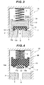
- Figure 3 shows a case of a high-pressure condition, that is, a case where a differential pressure between the high-pressure-side fluid passage 7 and the low-pressure-side fluid passage 8 is relatively high.
- the differential pressure at this time is, for example, at least 50 MPa.
- a load in the valve-closing direction acting on the valve body assembly 3A increases, so that the low-pressure seal portion 12 is compressively deformed and the valve body assembly 3A is further displaced in the valve-closing direction. Then the hard high-pressure seal portion 13 comes into contact with the valve seat body 4, thus performing sealing.
- the check valve 1A in the present embodiment allows the low-pressure seal portion 12 to come into close contact with the protrusion portion 6 at a low pressure, and the high-pressure seal portion 13 to come into close contact with the valve seat body 4 at a high pressure.
- the material of the low-pressure seal portion 12 is deformed for low sealability under a high pressure condition, while the material of the high-pressure seal portion 13 will not provide so high sealability under a low pressure condition.
- the present embodiment is configured so that sealing is performed by the low-pressure seal portion 12 at a low pressure and by the high-pressure seal portion 13 at a high pressure. This enables high sealability even in either case where a differential pressure between upstream and downstream flows is high or low.
- the low-pressure seal portion and the high-pressure seal portion are constituted out of materials having a low and a high hardness and, especially out of high polymer material in the same way as the above-described example, respectively.
- components overlapped with those in the above-described embodiment have the same reference characters and the description thereof are omitted. Furthermore, the overlapped descriptions made on operation and effect are also omitted.
- a valve body assembly 3B of a check valve 1B shown in Figure 4 includes a valve body 16 formed out of the same material as that of the high-pressure seal portion 13, for example, hard high polymer material such as polyimide.
- a soft seal portion 17 such as rubber is fixed so as to be stored in a recessed portion 16a formed in the center of the valve body 16.
- the valve body 16 is formed with an annular protrusion 18 facing the valve seat body 4 side and protruding along the valve opening/closing direction on the outside of a recessed portion 16a, and an end surface 18a of the protrusion 18 comes into contact with the valve seat body 4, thus performing sealing.
- the low-pressure seal portion 17 is fixed at a position surrounded by the protrusion 18, and the end surface 17a comes into contact with the valve seat body 4, thus performing sealing.
- the end surface 17a is positioned more inward of the valve body 16 in the axial direction (valve opening/closing direction and valve body contact/separation direction) than the end surface 18a.
- part of the valve body 16, that is, the protrusion 18 comes into contact with the valve seat body 4 in the same way as for the above-described high-pressure seal portion 13, thus performing sealing at a high pressure.
- This provides the like operation and effect with a smaller amount of parts than in the above-described embodiment.
- the whole valve seat body 4 may be formed into a flat shape without providing the protrusion portion 6 (refer to Figure 1) on the valve seat body 4 side, like the check valve 1B shown in Figure 4 and a check valve 1C shown in Figure 5.
- provision of a step-off or an incline on a seal portion on the valve body side enables adjustment of the timings of contacts of the valve seat body 4 with the low-pressure seal portions 17, 12 and the high-pressure seal portions 18, 13.
- a check valve 1D shown in Figure 6 may be used.
- a ring-shaped low-pressure seal portion 20 and a high-pressure seal portion 21 positioned on the outside of the low-pressure seal portion 20 in a diametrical direction are fixed so as to be stored in the annular recessed portion 19a provided in the valve body 19.
- the seal portions 20, 21 are respectively formed out of the same high polymer material as the seal portions 12, 13 and have the like operation and effect.
- a check valve 1E shown in Figure 7 may be used.
- the check valve 1E is not formed with such a protrusion 6 that the check valve 1A has.
- a ring-shaped low-pressure seal portion 22 and the high-pressure seal portion 23 positioned on the outside of the low-pressure seal portion 22 are fixed so as to be stored in the annular recessed portion 19a provided in the valve body 19.
- Each of the seal portions 22, 23 are of a cylindrical shape.
- Figure 8 is a view of a check valve 1F according to a second embodiment of the present invention.
- layouts of the low-pressure seal portion and the high-pressure seal portion have a reverse relationship between the inside and outside in a diametrical direction of the valve body 24 (direction orthogonal to valve opening/closing direction and a flowing direction of fluid introduced from the high-pressure-side fluid passage 7).
- a ring-shaped low-pressure seal portion 25 and a high-pressure seal portion 26 positioned on the inside of the low-pressure seal portion 25 in a diametrical direction are fixed so as to be stored in an annular recessed portion 24a provided in the valve body 24.
- the low-pressure seal portion 25 is disposed upstream of the high-pressure seal portion 26 in a flowing direction of fluid.
- a front end portion of the low-pressure seal portion 25 including at least an end surface 25a and a front end portion of the high-pressure seal portion 26 including at least an end surface 26a are laid out in parallel to each other in a direction orthogonal to a valve opening/closing direction of the valve body assembly 3F (valve body contact/separation direction).
- sealing is performed as follows. Specifically, in such a condition as seen in Figure 9 showing that a differential pressure between upstream and downstream flows is low (at lower than a predetermined value), the end surface 25a of the low-pressure seal portion 25 comes into contact with the valve seat body 4, thus performing sealing. Under this low-pressure condition, no contact is made between the high-pressure seal portion 26 and the valve seat body 4.
- a differential pressure actually acting on the high-pressure seal portion 13 is a differential pressure acting on a ring-shaped region surrounded by the outer periphery of the high-pressure seal portion 26 and the outer periphery of the valve body 24 when viewed from the top of the valve body in a differential-pressure working direction (vertical direction in Figure 10).
- the high-pressure seal portion 26 is positioned inward (downstream side) in a diametrical direction, of the high-pressure seal portion 13 in the check valve 1A shown in Figure 1, thus relatively widening the ring-shaped region. Accordingly, a differential pressure between upstream and downstream flows can be made to effectively act on the high-pressure seal portion 26, thus improving sealability under a high pressure condition.
- the check valve 1F can be miniaturized by reducing a length in the contact/separation direction, or a stroke in the contact/separation direction can be increased if the check valve 1F is of the same size.
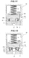
- a check valve 1G formed with a valve body assembly 3G shown in Figure 11 may be used.
- the high-pressure seal portion 26 and the valve body assembly 3G is composed of a valve body 28 constituted out of hard high polymer such as polyimide and a soft low-pressure seal portion 25 such as rubber, fixed in an annular recessed portion 28a formed in the valve body 28.
- a protrusion 29 formed by protruding a central portion (a part) of a surface facing the valve seat body 4 side of the valve body 28 toward valve seat body 4 side (valve opening/closing direction).
- the protrusion 29 functions as a high-pressure seal portion and an end surface 29a of the protrusion 29 comes into contact with the seat 4, thus performing sealing at a high pressure.
- the protrusion portion 6 may be provided on the valve 4 side like a check valve 1H shown in Figure 12.
- the protrusion portion 6 is provided as compared to the check valve 1F. Accordingly, it is only necessary to adjust contact timing of the soft low-pressure seal portion 25 and the hard high-pressure seal portion 26 by changing heights of the low-pressure seal portion 25 and the high-pressure seal portion 26 as necessary.
- FIG. 13 is a view of a check valve 1l according to a third embodiment of the present invention.
- the check valve 1l is formed with a soft valve-seat-side low-pressure seal portion 30 fixed on the valve seat body 4, and the valve-seat-side low-pressure seal portion 30 constitutes a valve seat portion along with the valve seat body 4.
- the valve-seat-side low-pressure seal portion 30 may use the same or different type of material as or from the low-pressure seal portion 25, for example, polyimide, if the material is softer than that of the valve seat body 4.
- the valve-seat-side low-pressure seal portion 30 is of a ring shape and is provided at a position facing the low-pressure seal portion 25.
- the valve body assembly 31 has the same configuration, for example, as the valve body assembly 3F shown in Figure 8, however, heights of the low-pressure seal portion 25 and the high-pressure seal portion 26 are adjusted as necessary so as to appropriately perform sealing at a low pressure and a high pressure as described below.
- sealing is performed as follows. Specifically, in such a condition as seen in Figure 14 showing that a differential pressure between upstream and downstream flows is low (at lower than a predetermined value), the end surface 25a of the low-pressure seal portion 25 comes into contact with the valve-seat-side low-pressure seal 30, thus performing sealing. Under this low-pressure condition, no contact is made between the high-pressure seal portion 26 and the valve seat body 4.
- each of the low-pressure seal portion 25 and the valve-seat-side low-pressure seal portion 30 bends inward (downstream side) in a diametrical direction to lose a sealing function, so that a differential pressure between upstream and downstream flows can be made to effectively act on the high-pressure seal portion 26 as in the embodiment shown in Figure 8 and others, thus improving sealability under a high pressure condition.
- the present embodiment formed with the valve-seat-side low pressure seal portion 30, has the following effect: That is to say, if there is no valve-seat-side low-pressure seal portion 30, the low-pressure seal portion 25 slides against the valve seat body 4, which may accelerate wear to the low-pressure seal portion 25.
- the low-pressure seal portion 25 comes into contact only the valve-seat-side low-pressure seal portion 30 without direct contact with the valve seat body 4. This can restrain the low-pressure seal portion 25 from being worn, thus improving durability.
- the protrusion portion 6 may be provided on the valve seat body 4 side like a check valve 1 J shown in Figure 16.
- the check valve 1I in Figure 13 it is only necessary to adjust contact timing of the low-pressure seal portion 25 and the high-pressure seal portion 26 by changing heights of the low-pressure seal portion 25 and the high-pressure seal portion 26 as necessary.
- a check valve 1K formed with a valve body assembly 3K shown in Figure 17 may be used.
- the high-pressure seal portion 26 ( Figure 16) separate from the valve body assembly 3K is not provided, like the check valve 1G in Figure 11.
- the valve body assembly 3K is composed of a valve body 32 constituted of hard high polymer material such as polyimide and a low-pressure seal portion 25, such as rubber, fixed inside an annular recessed portion 32a formed in the valve body 32.
- a protrusion 33 formed by protruding a central portion (a part) of a surface facing the valve seat body 4 of the valve body 32 toward valve seat body 4.
- the protrusion 33 functions as a high-pressure seal portion and an end surface 33a of the protrusion 33 comes into contact with the valve seat body 4, thus performing sealing at a high pressure.
- FIG 18 is a view of a check valve 1L according to a fourth embodiment of the present invention.
- a valve body assembly 3L of the check valve 1L is formed by fixing a low-pressure seal portion 36 and a high-pressure seal portion 37 provided on the inside of the low-pressure seal portion 36 in a diametrical direction inside an annular recessed portion 35a provided in a valve body 35.
- the low-pressure seal portion 36 is formed with a cylindrical portion 36a hung from the recessed portion 35a and a flange portion 36b substantively extending horizontally inward from a lower edge of a cylindrical portion 36a.
- a coil spring 38 (restoring member) for supporting a flange portion 36b, one end and the other end which are supported on the valve body 35 and the flange portion 36b, respectively.
- the plurality of coil springs 38 (two shown in Figure 18) are provided at regular intervals in a peripheral direction of the check valve 1L.
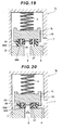
- sealing is performed as follows. In other words, in such a condition as seen in Figure 19 showing that a differential pressure between upstream and downstream flows is low (at lower than a predetermined value), a lower surface of the flange portion 36b of the low-pressure seal portion 36 comes into contact with the valve seat body 4, thus performing sealing. Under this low-pressure condition, no contact is made between the high-pressure seal portion 37 and the valve seat body 4.
- a differential pressure lowers from a high pressure condition shown in Figure 20 and, when shifting to a low pressure condition, the low-pressure seal portion 36 rapidly restores to its original condition as shown in Figure 19 by the repulsion of the coil spring 38.
- restoration of the low-pressure seal portion 36 may delay due to a creep phenomenon or sealability under a low pressure condition may degrade due to some wear to the low-pressure seal portion 36 caused by repeating sliding against the valve seat body 4.
- the coil spring 38 permits the low-pressure seal portion 36 to rapidly and positively press the valve seat body 4 at a predetermined pressure or higher for restoration, thus ensuring high sealability.
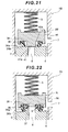
- a check valve 1 M shown in Figure 21 may be used.
- a valve body assembly 3M of the check valve 1 M is composed of a valve body 40 constituted out of hard high polymer material such as polyimide and the low-pressure seal portion 36 and the coil spring 38 fixed inside an annular recessed portion 40a formed in the valve body 40.
- a protrusion 41 formed by protruding a central portion (a part) of a surface facing the valve seat body 4 of the valve body 40 toward valve seat body 4.
- the protrusion 41 functions as a high-pressure seal portion and an end surface 41 a of the protrusion 41 comes into contact with the valve seat body 4, thus performing sealing.
- the protrusion portion 6 may be provided on the valve seat body 4 side like a check valve 1 N shown in Figure 22. In this deformed example, it is only necessary to adjust contact timings of the low-pressure seal portion 36 and the high-pressure seal portions 37 by changing heights of the low-pressure and high-pressure seal portions 36, 37 as necessary.
- Figures 23-25 show deformed examples using a leaf spring 45.
- the leaf spring 45 is provided inside the low-pressure seal portion 36 in a diametrical direction, base end of which is inserted into the valve body 35 and front end elastically supports the flange portion 36b.
- Figure 24 is a view showing a deformed example using the leaf spring 46 inserted into the low-pressure seal portion 36.
- the leaf spring 46 base end of which is inserted into the valve body 35, is inserted into a cylindrical portion 36a and the flange portion 36b, which permits the whole low-pressure seal portion 36 to be elastically supported.
- Figure 25 is a view showing a deformed example using the leaf spring 47 inserted in the low-pressure seal portion 36.
- the base end of the leaf spring 47 is fixed, sandwiched between the valve body 35 and the low-pressure seal portion 36, and the front end thereof is fixed with the low-pressure seal portion 36.
- a restoring force can be given so that the low-pressure seal portion 36 may be rapidly restored from an inward compressively-deformed condition to its original condition, in the same way as for the coil spring 38.
- Figure 26 is a view showing a deformed example using rubber 48 provided on the inside of the low-pressure seal portion 36.
- the rubber 48 of a ring shape, is provided around the axis of the valve body 35 and circular in cross section.
- the rubber may be rectangular in cross section like the rubber 49 of another deformed example shown in Figure 27.
- a restoring force may be given to the low-pressure seal portion 36 so as to rapidly restore it from an inward compressively-deformed condition to its original condition by means of an elastic force owned by the material itself.
- any elastic body may be used as a restoring member for giving a restoring force to the low-pressure seal portion 36 in this way.
- the spring 5 is not always required.
- a main stop valve or a regulating valve may be used if it is a type of fluid on-off valve device.
- a fluid consuming apparatus such as a fuel cell for generating power by an electrochemical reaction of fuel gas and oxygen gas and an internal combustion engine for a fuel cell powered vehicle which drives a running motor with generated electric power (electric energy) of the fuel cell and a natural gas powered vehicle which obtains driving power for running by means of heat energy obtained by burning natural gas (CNG) with an internal combustion engine
- a main stop valve (root valve) or a on-off valve for controlling the presence of fuel gas supply from a fuel gas supply source to a fuel gas consuming apparatus, one or a plurality of check valves for preventing counter-flow of fuel gas in a fuel gas flow path, one or a plurality of excessive flow prevention valves for preventing abnormal rise in fuel gas flow rate in a fuel gas flow path, one or a plurality of relief valves for preventing abnormal rise in fuel gas pressure in a fuel gas flow path, or one or a plurality of regulating valves for a main stop valve (root valve) or a on-off valve for controlling the presence of fuel gas supply from
- the low-pressure seal portion may use synthetic rubber such as polybutadiene group, butadiene-acrylonitrile group or chloroprene group as well as natural rubber.
- the high-pressure seal portion may use thermoplastic resin such as polyethylene (PE), polypropylene (PP), polyvinylchloride (PVC) or polystyrene (PS), or thermosetting resin such as phenol resin (PF), epoxy resin (EP) or alkyd resin as well as metals.
- the respective seal portions may be disposed on either one or both of the valve body and the valve seat portion.
- the present invention permits selective sealing between a valve body and a valve seat portion using a plurality of seal portions having different hardnesses from each other even in either case where a differential pressure between upstream and downstream paths in a fluid passage is in a predetermined high-pressure state or a predetermined low-pressure state.
- a first seal portion comes into close contact with a valve seat portion and when the differential pressure is a predetermined value or higher (at a high pressure), a second seal portion comes into close contact with the valve seat portion, by which appropriate selection of the material of each seal portion ensures high sealability in either case where a differential pressure between upstream and downstream flows is high or low.
- the present invention can be widely used in a variety of applications to fluid on-off valve devices having their requirements.
Landscapes
- Engineering & Computer Science (AREA)
- General Engineering & Computer Science (AREA)
- Mechanical Engineering (AREA)
- Physics & Mathematics (AREA)
- Architecture (AREA)
- Fluid Mechanics (AREA)
- Check Valves (AREA)
- Lift Valve (AREA)
- Details Of Valves (AREA)
Abstract
Description
- The present invention relates to a fluid on-off valve device for opening and closing a fluid passage.
- As a sealing method for a valve part for high-pressure fluid in high-pressure on-off valve device (a fluid on-off valve device) for opening and closing a high-pressure fluid passage, there has been generally known a method of attaching a seal member formed out of any type of rubber, resin and metal onto a valve body as a movable part and locating the seal member on a valve seat portion to seal fluid, for example, as disclosed in
Japanese Patent Laid-Open Publication No. 2002-295711 - Use of rubber as a seal member provides high sealability and, at the same time, poor pressure resistance. For example, under such a high-pressure condition that a differential pressure between upstream and downstream paths in a fluid passage is higher than 50 MPa, sealing failure may be caused by a squeezing-out phenomenon due to excessive compressive deformation of a seal member.
- On the other hand, use of resin and metal as a seal member facilitates to ensure pressure resistance and sealability under such a condition that the differential pressure is high, for example, higher than 50 MPa, while may cause difficult sealing under a relatively low differential pressure, for example, lower than 50 MPa.
- In view of the aforementioned problems, it is an object of the present invention to provide a fluid on-off valve device capable of attaining high sealability in either case where a differential pressure between upstream and downstream paths in a fluid passage is high or low.
- The fluid on-off valve device according to the present invention includes: a valve seat portion; a valve body which contacts and separates from the valve seat portion to communicate and block a fluid passage and a plurality of seat portions which selectively seal between the valve body and the valve seat portion. The plurality of seal portions have different hardnesses from each other and a differential pressure between upstream and downstream paths in the fluid passage switches a seal portion which seals between the valve body and the valve seat portion to any of the other seal portions having different hardnesses.
- Such a configuration permits selective sealing between a valve body and a valve seat portion using a plurality of seal portions having different hardnesses (in other words, elastic modulus, coefficient of elasticity and rigidity) from each other even in either case where a differential pressure between upstream and downstream paths in a fluid passage is in a predetermined high-pressure condition or a predetermined low-pressure condition. The seal portion may be disposed on either one or both of the valve body and the valve seat portion.
- In the fluid on-off valve device, a direction in which the valve body contacts and separates from the valve seat portion and a flow direction of the fluid introduced from the upstream path in the fluid passage cross each other, and the plurality of seal portions may be arranged, respectively, in parallel to the orthogonal to the valve body contact/separation direction.
- Such a configuration can attain miniaturization of a valve device by reducing the length in the valve body contact/separation direction as compared to a serial layout of a plurality of seal portions in the valve body contact/separation direction. Otherwise, it can increase a stroke in the valve body contact/separation direction if it is of the same size.
- In the plurality of seal portions of the fluid on-off valve device, a distance from an end surface in close contact with the valve seat portion to the valve seat portion may become longer as its hardness is higher and the distance may become shorter as its hardness is lower.
- In such a configuration, a seal portion having lower hardness contacts with the valve seat portion earlier than a seal portion having higher hardness.
- In the fluid on-off valve device, a restoring member giving a restoring force to compressive deformation may be provided for at least a seal portion having the lowest hardness of the plurality of seal portions.
- Such a configuration, when a differential pressure between upstream and downstream flows shifts from a predetermined high-pressure condition to a predetermined low-pressure condition, allows an earlier compressively-deformed seal portion having low hardness to be immediately restored to its original shape optimum to a seal in a low-pressure condition, as well as assurance of a seal pressure in a high-pressure condition.
- The fluid on-off valve device of the present invention includes a valve seat portion, a valve body which contacts and separates from the valve seat portion to block and communicate between upstream and downstream paths in a fluid passage. The valve body includes a first seal portion sealing between the valve seat portion and the valve body and a second seal portion having higher hardness than the first seal portion. In the fluid on-off valve device, when a differential pressure between the upstream and downstream paths in a fluid passage is lower than a predetermined value, the first seal portion comes into close contact with the valve seat portion to block the fluid passage. On the other hand, when the differential pressure is the predetermined value or higher, the first seal portion in close contact with the valve seat portion is compressively deformed by the differential pressure and the second seal portion comes into close contact with the valve seat portion to block the fluid passage.
- Such a configuration permits fluid to be sealed by different seal portions depending upon whether a differential pressure between upstream and downstream paths in a fluid passage is high or low. In other words, when the differential pressure between the upstream and downstream paths in a fluid passage is lower than a predetermined value, a first seal portion having relatively low hardness comes into close contact with a valve seat portion. On the other hand, at the predetermined value or higher, a second seal portion having relatively high hardness comes into contact with the valve seat portion.
- Accordingly, proper selection of the material of each seal portion provides high sealability for both cases where the differential pressure is high and low. For example, the first seal portion may use a soft material such as rubber (in other words, elastic modulus, rigidity and hardness are all low), while the second seal portion may use a material harder than the first seal portion (in other words, elastic modulus, rigidity and hardness are all high), such as resin and metal.
- In the fluid on-off valve device according to the present invention, part of the valve body may constitute the second seal portion.
- Such a configuration constitutes the second seal portion out of the valve body itself, thus restraining the number of parts from increasing.
- In the fluid on-off valve device according to the present invention, a direction in which the valve body contacts and separates from the valve seat portion and a flow direction of the fluid introduced from the upstream path in the fluid passage cross each other, and the first seal portion may be disposed on the upstream side of the second seal portion in the flow direction.
- Such a configuration locates the first seal portion and the second seal portion on the upstream side (high-pressure side) and downstream side (low-pressure side), respectively. When a differential pressure between upstream and downstream paths shifts from a low-pressure condition (less than the predetermined value) to a high-pressure condition (a predetermined value or higher), the increasing differential pressure allows the first seal portion to be deformed so as to fall down toward the downstream side from the upstream side in a flow direction of fluid, by which sealability is lost and a differential pressure acts on, mainly, the second seal portion. At this time, a differential pressure actually acting on the second seal portion is a differential pressure acting on a ring-shaped region surrounded by the outer periphery of the second seal portion and the outer periphery of the valve body when viewed from the top of the valve body in a differential-pressure working direction.
- Accordingly, the above-described configuration permits the ring-shaped region to be relatively widened more than a case where the second seal portion is located more outward (upstream side) in a diametrical direction than the first seal portion. This permits the differential pressure between upstream and downstream paths to be effectively made to effectively work on the second seal portion, thus improving sealability under a high-pressure condition.
- In the fluid on-off valve device, a direction in which the valve body contacts and separates from the valve seat portion and a flow direction of the fluid introduced from the upstream path in the fluid passage cross each other, and the first seal portion and the second seal portion may be disposed in parallel to, each other, the orthogonal direction to the direction in which the valve body contacts and separates from the valve seat portion.
- Such a configuration can attain miniaturization of a valve device by reducing the length in the valve body contact/separation direction as compared to a serial layout of the first and second seal portions in the valve body contact/separation direction. Otherwise, it can increase a stroke in the valve body contact/separation direction if the valve body is of the same size.
- In the fluid on-off valve device, a distance from an end surface in close contact with the valve seat portion of the first seal portion to the valve seat portion may be set so as to be shorter than that from an end surface in close contact with the valve seat portion of the second seal portion to the valve seat portion.
- Such a configuration allows the first seal portion having relatively low hardness to contact a valve seat portion earlier than the second seal portion having relatively high hardness.
- The fluid on-off valve device according to the present invention may be formed with restoring member for giving a restoring force to the compressively deformed first seal portion.
- Such a configuration, when a differential pressure between upstream and downstream flows shifts from a high-pressure condition (a predetermined value or higher) to a low-pressure condition (less than the predetermined value), permits the first seal portion to be immediately restored to its original shape optimum to a seal in a low-pressure condition, as well as assurance of a predetermined or higher seal pressure.
- The fluid on-off valve device according to the present invention may be configured so as to constitute the valve seat portion out of a valve seat body and a valve-seat-side seal portion softer than the valve seat body and to make the valve-seat-side seal portion face the first seal portion.
- Such a configuration performs sealing by bringing the first seal portion into close contact with the valve-seat-side seal portion. In other words, the first seal portion comes into no direct contact with the valve seat body, which restrains the first seal portion from being worn by the first seal portion sliding against the valve seat body.
- Of the plurality of seal portions, the seal portion having relatively low hardness may be constituted out of any of rubber, resin and metal, while the seal portion having relatively high hardness may be constituted out of either of resin or metal.
- The first seal portion may be constituted out of any of rubber, resin and metal, while the second seal portion may be constituted out of either of resin or metal.
- The fluid on-off valve body according to the present invention may be provided in a fluid passage through which such high pressure gas that a differential pressure between upstream and downstream pressures is a predetermined pressure or higher (for example, 1 MPa or more) flows. In this case, the high-pressure gas may be fuel gas supplied for generation of electric energy or heat energy and further the fuel gas may be hydrogen gas or natural gas (CNG).
- The fluid on-off valve body according to the present invention may be any of a check valve, a on-off valve and a relief valve provided in the fluid passage.
-
- Figure 1 is a longitudinal sectional view of a check valve according to a first embodiment of the present invention;
- Figure 2 is a longitudinal sectional view showing a state of the check valve under a low-pressure condition;
- Figure 3 is a longitudinal sectional view showing a state of the check valve under a high-pressure condition;
- Figure 4 is a longitudinal sectional view showing a deformed example of the check valve;
- Figure 5 is a longitudinal sectional view showing a deformed example of the check valve;
- Figure 6 is a longitudinal sectional view showing a deformed example of the check valve;
- Figure 7 is a longitudinal sectional view showing a deformed example of the check valve;
- Figure 8 is a longitudinal sectional view of a check valve according to a second embodiment of the present invention;
- Figure 9 is a longitudinal sectional view showing a state of the check valve under a low-pressure condition;
- Figure 10 is a longitudinal sectional view showing a state of the check valve under a high-pressure condition;
- Figure 11 is a longitudinal sectional view showing a deformed example of the check valve;
- Figure 12 is a longitudinal sectional view showing a deformed example of the check valve;
- Figure 13 is a longitudinal sectional view of a check valve according to a third embodiment of the present invention;
- Figure 14 is a longitudinal sectional view showing a state of the check valve under a low-pressure condition;
- Figure 15 is a longitudinal sectional view showing a state of the check valve under a high-pressure condition;
- Figure 16 is a longitudinal sectional view showing a deformed example of the check valve;
- Figure 17 is a longitudinal sectional view showing a deformed example of the check valve;
- Figure 18 is a longitudinal sectional view of a check valve according to a fourth embodiment of the present invention;
- Figure 19 is a longitudinal sectional view showing a state of the check valve under a low-pressure condition;
- Figure 20 is a longitudinal sectional view showing a state of the check valve under a high-pressure condition;
- Figure 21 is a longitudinal sectional view showing a deformed example of the check valve;
- Figure 22 is a longitudinal sectional view showing a deformed example of the check valve;
- Figure 23 is a partially sectional view showing a deformed example of a restoring member supporting a low-pressure seal portion;
- Figure 24 is a partially sectional view showing a deformed example of a restoring member supporting a low-pressure seal portion;
- Figure 25 is a partially sectional view showing a deformed example of a restoring member supporting a low-pressure seal portion;
- Figure 26 is a partially sectional view showing a deformed example of a restoring member supporting a low-pressure seal portion; and
- Figure 27 is a partially sectional view showing a deformed example of a restoring member supporting a low-pressure seal portion.
- With reference to the accompanying drawings, description will be given below of embodiments according to the present invention.
- Figure 1 is, for example, a valve provided in a high-pressure fluid passage, and is a check valve (fluid on-off valve device) 1A which permits flowing of fluid in one direction, but prohibits flowing of fluid in any other direction. The
check valve 1A is disposed with a valve body assembly (valve element) 3A influid passages valve body 2. Thevalve body assembly 3A stops flowing fluid into a low-pressure-side fluid passage (downstream passage) 8 on a downstream side in a fluid flowing direction from a high-pressure-side fluid passage (upstream passage) 7 on an upstream side in a fluid flowing direction. - On the low-pressure side of the
valve body 2, a valve seat body (valve seat portion) 4 constituting a seal in cooperation with thevalve body assembly 3A is formed. In thevalve body 2, aspring 5 is provided to give a restoring force in such a direction as to separate from thevalve seat body 4 to thevalve body assembly 3A. On the central side of thevalve seat body 4, there is formed a protrusion portion 9 protruding to thevalve body assembly 3A side, surrounding an opening edge of the low-pressureside fluid passage 8. Thesevalve seat body 4 andprotrusion portion 6 constitutes a valve seat portion. - The
valve body assembly 3A is constituted by fixing a low-pressure seal portion (first seal portion) 12 and a high-pressure seal portion (second seal portion) 13 on avalve body 10 having H-shaped cross section. Each of theseal portions pressure seal portion 12 is formed out of material softer than the high-pressure seal portion 13, that is, out of material having relatively low hardness. Specifically, as the low-pressure seal portion 12, rubber may be used and, as the high-pressure seal portion 13, resin which has relatively high hardness may be used. - The high-
pressure seal portion 13 is fixed so as to be stored in a lower surface of thevalve body 10, that is, a recessedportion 10a formed in a surface facing thevalve seat body 4, so that a ring-shapedend surface 13a protruding to thevalve seat body 4 side comes into contact with thevalve seat body 4, thus performing sealing. - The low-
pressure seal portion 12 is fixed on the high-pressure seal portion 13 so as to be completely stored in a region surrounded by theend surface 13a of the high-pressure seal portion 13, that is, in the recessedportion 13b formed in the center of the high-pressure seal portion 13. Then, the end surface (surface facingvalve seat body 4 side) 12a of the low-pressure seal portion 12 comes into contact with theprotrusion portion 6, thus performing sealing. - The
end surface 12a of the low-pressure seal portion 12 is positioned more inward of thevalve body 10 in the axial direction (valve opening/closing direction and valve contact/separation direction) than theend surface 13a of the high-pressure seal portion 13, while a difference in the height along the valve opening/closing direction between theseend surfaces protrusion portion 6. Accordingly, besides such a condition that theend surface 12a and the end surface of theprotrusion portion 6 in uniform contact with each other, even if thevalve body assembly 3A further moves in the valve-closing direction and the low-pressure seal portion 12 is pressed against theprotrusion portion 6 for compressive deformation, theend surface 13a of the high-pressure seal portion 13 will come into no contact with thevalve seat body 4 as shown in Figure 2, provided that the deformed amount is at a predetermined level or lower. - In other words, the timing of a contact of the
end surface 12a with theprotrusion portion 6 is different from that of theend surface 13a with thevalve seat body 4. That is, a distance between theend surface 12a of the low-pressure seal portion 12 having relatively low hardness and theprotrusion portion 6 is smaller than that between theend surface 13a of the high-pressure seal portion 13 having relatively high hardness and thevalve seat body 4. - Next, the operation of the
check valve 1A will be described below. In thecheck valve 1A, when a fluid pressure of the high-pressure fluid passage 7 rises, a load in a valve-closing direction corresponding to a differential pressure between the fluid pressure and a fluid pressure of the low-pressure-side fluid passage 8 and a receiving area of the differential pressure (hereinafter referred to as valve-closing direction load) acts on thevalve body 10, and thevalve body assembly 3A moves to thevalve seat body 4 side against the restoring force of thespring 5. - Figure 2 shows a case of a low-pressure condition, that is, a case where a differential pressure between the high-pressure-
side fluid passage 7 and the low-pressure-side fluid passage 8 is relatively low. The differential pressure at this time is, for example, 1 MPa (inclusive) to 50 MPa (exclusive). Under this condition, the soft low-pressure seal portion 12 comes into close contact with theprotrusion portion 6, thus performing sealing. At this time, no contact is made between the hard high-pressure seal portion 13 and the valve-seat body 4. - Figure 3 shows a case of a high-pressure condition, that is, a case where a differential pressure between the high-pressure-
side fluid passage 7 and the low-pressure-side fluid passage 8 is relatively high. The differential pressure at this time is, for example, at least 50 MPa. Under this condition, a load in the valve-closing direction acting on thevalve body assembly 3A increases, so that the low-pressure seal portion 12 is compressively deformed and thevalve body assembly 3A is further displaced in the valve-closing direction. Then the hard high-pressure seal portion 13 comes into contact with thevalve seat body 4, thus performing sealing. - In this way, the
check valve 1A in the present embodiment allows the low-pressure seal portion 12 to come into close contact with theprotrusion portion 6 at a low pressure, and the high-pressure seal portion 13 to come into close contact with thevalve seat body 4 at a high pressure. Usually, the material of the low-pressure seal portion 12 is deformed for low sealability under a high pressure condition, while the material of the high-pressure seal portion 13 will not provide so high sealability under a low pressure condition. The present embodiment is configured so that sealing is performed by the low-pressure seal portion 12 at a low pressure and by the high-pressure seal portion 13 at a high pressure. This enables high sealability even in either case where a differential pressure between upstream and downstream flows is high or low. - Next, a deformed example of the
check valve 1A will be described below. In each of the examples described below, the low-pressure seal portion and the high-pressure seal portion are constituted out of materials having a low and a high hardness and, especially out of high polymer material in the same way as the above-described example, respectively. In the following description, components overlapped with those in the above-described embodiment have the same reference characters and the description thereof are omitted. Furthermore, the overlapped descriptions made on operation and effect are also omitted. - A
valve body assembly 3B of acheck valve 1B shown in Figure 4 includes avalve body 16 formed out of the same material as that of the high-pressure seal portion 13, for example, hard high polymer material such as polyimide. Asoft seal portion 17 such as rubber is fixed so as to be stored in a recessedportion 16a formed in the center of thevalve body 16. - The
valve body 16 is formed with anannular protrusion 18 facing thevalve seat body 4 side and protruding along the valve opening/closing direction on the outside of a recessedportion 16a, and anend surface 18a of theprotrusion 18 comes into contact with thevalve seat body 4, thus performing sealing. The low-pressure seal portion 17 is fixed at a position surrounded by theprotrusion 18, and theend surface 17a comes into contact with thevalve seat body 4, thus performing sealing. Theend surface 17a is positioned more inward of thevalve body 16 in the axial direction (valve opening/closing direction and valve body contact/separation direction) than theend surface 18a. - According to the deformed example, part of the
valve body 16, that is, theprotrusion 18 comes into contact with thevalve seat body 4 in the same way as for the above-described high-pressure seal portion 13, thus performing sealing at a high pressure. This provides the like operation and effect with a smaller amount of parts than in the above-described embodiment. - As another deformed example, the whole
valve seat body 4 may be formed into a flat shape without providing the protrusion portion 6 (refer to Figure 1) on thevalve seat body 4 side, like thecheck valve 1B shown in Figure 4 and acheck valve 1C shown in Figure 5. In this case, provision of a step-off or an incline on a seal portion on the valve body side enables adjustment of the timings of contacts of thevalve seat body 4 with the low-pressure seal portions pressure seal portions - For example, in the
check valve 1B shown in Figure 4, noprotrusion portion 6 is provided on thevalve seat body 4. Accordingly, to compensate for it, theend surface 17a of the low-pressure seal portion 17 in thevalve body assembly 3B protrudes to thevalve seat body 4 more than theend surface 18a of theprotrusion 18 constituting a high-pressure seal portion in a reverse way to the configuration of thecheck valve 1A in Figure 1. At valve-closing operation, this permits theprotrusion 18 constituting a high-pressure seal portion to perform sealing after sealing is first performed by the low-pressure seal portion 12. - Similarly, in the
check valve 1C shown in Figure 5, noprotrusion portion 6 is provided on thevalve seat body 4. Accordingly, to compensate for it, theend surface 12a of the low-pressure seal portion 12 in thevalve body assembly 3C protrudes to thevalve seat body 4 side more than theend surface 13a of the high-pressure seal portion 13 in a reverse way to the configuration of thecheck valve 1A in Figure 1. At valve-closing operation, this permits the high-pressure seal portion 13 to perform sealing after sealing is first performed by the low-pressure seal portion 12. - As another deformed example of the
check valve 1A in Figure 1, acheck valve 1D shown in Figure 6 may be used. On avalve body assembly 3D of thecheck valve 1D, a ring-shaped low-pressure seal portion 20 and a high-pressure seal portion 21 positioned on the outside of the low-pressure seal portion 20 in a diametrical direction are fixed so as to be stored in the annular recessedportion 19a provided in thevalve body 19. Theseal portions seal portions - As yet another deformed example of the
check valve 1A in Figure 1, acheck valve 1E shown in Figure 7 may be used. Thecheck valve 1E is not formed with such aprotrusion 6 that thecheck valve 1A has. On avalve body assembly 3E, a ring-shaped low-pressure seal portion 22 and the high-pressure seal portion 23 positioned on the outside of the low-pressure seal portion 22 are fixed so as to be stored in the annular recessedportion 19a provided in thevalve body 19. Each of theseal portions - This deformed example, having ring-shaped
seal portions seal portions - Figure 8 is a view of a
check valve 1F according to a second embodiment of the present invention. In the present embodiment, as compared to thecheck valve 1E in Figure 7, layouts of the low-pressure seal portion and the high-pressure seal portion have a reverse relationship between the inside and outside in a diametrical direction of the valve body 24 (direction orthogonal to valve opening/closing direction and a flowing direction of fluid introduced from the high-pressure-side fluid passage 7). Specifically, on avalve body assembly 3F of thecheck valve 1F, a ring-shaped low-pressure seal portion 25 and a high-pressure seal portion 26 positioned on the inside of the low-pressure seal portion 25 in a diametrical direction are fixed so as to be stored in an annular recessedportion 24a provided in thevalve body 24. - That is to say, the low-
pressure seal portion 25 is disposed upstream of the high-pressure seal portion 26 in a flowing direction of fluid. In other words, a front end portion of the low-pressure seal portion 25 including at least anend surface 25a and a front end portion of the high-pressure seal portion 26 including at least anend surface 26a are laid out in parallel to each other in a direction orthogonal to a valve opening/closing direction of thevalve body assembly 3F (valve body contact/separation direction). - In the present embodiment, sealing is performed as follows. Specifically, in such a condition as seen in Figure 9 showing that a differential pressure between upstream and downstream flows is low (at lower than a predetermined value), the
end surface 25a of the low-pressure seal portion 25 comes into contact with thevalve seat body 4, thus performing sealing. Under this low-pressure condition, no contact is made between the high-pressure seal portion 26 and thevalve seat body 4. - On the other hand, under such a condition as seen in Figure 10 showing that a differential pressure between upstream and downstream flows is high (at a predetermined value or higher), a large valve-closing-direction load further acts on the
valve body assembly 3F, so that the low-pressure seal portion 25 attempts to have further compressive deformation due to an increased differential pressure. However, because a high pressure from the high-pressure-side fluid passage 7 acts on the low-pressure seal portion 25, the low-pressure seal portion 25 falls down to the downstream side (the inside in the diametrical direction in Figure 10). This impairs sealability by the low-pressure seal portion 25, however, theend surface 26a of the high-pressure seal portion 26 comes into close contact with thevalve seat body 4 to ensure sealability by the high-pressure seal portion 26. - At this time, a differential pressure actually acting on the high-
pressure seal portion 13 is a differential pressure acting on a ring-shaped region surrounded by the outer periphery of the high-pressure seal portion 26 and the outer periphery of thevalve body 24 when viewed from the top of the valve body in a differential-pressure working direction (vertical direction in Figure 10). - In the
check valve 1F of the present embodiment, the high-pressure seal portion 26 is positioned inward (downstream side) in a diametrical direction, of the high-pressure seal portion 13 in thecheck valve 1A shown in Figure 1, thus relatively widening the ring-shaped region. Accordingly, a differential pressure between upstream and downstream flows can be made to effectively act on the high-pressure seal portion 26, thus improving sealability under a high pressure condition. - Furthermore, as compared to such a configuration that the low-
pressure seal portion 25 and the high-pressure seal portion 26 are arranged in series in a contact/separation direction of thevalve body assembly 3F, thecheck valve 1F can be miniaturized by reducing a length in the contact/separation direction, or a stroke in the contact/separation direction can be increased if thecheck valve 1F is of the same size. - As a deformed example of the present embodiment, a
check valve 1G formed with avalve body assembly 3G shown in Figure 11 may be used. In a deformed example shown in Figure 11, as compared to thecheck valve 1F, there is not provided the high-pressure seal portion 26 and thevalve body assembly 3G is composed of avalve body 28 constituted out of hard high polymer such as polyimide and a soft low-pressure seal portion 25 such as rubber, fixed in an annular recessedportion 28a formed in thevalve body 28. - At a central portion of the
valve body 28 in the diametrical direction, there is provided aprotrusion 29 formed by protruding a central portion (a part) of a surface facing thevalve seat body 4 side of thevalve body 28 towardvalve seat body 4 side (valve opening/closing direction). In this deformed example, theprotrusion 29 functions as a high-pressure seal portion and anend surface 29a of theprotrusion 29 comes into contact with theseat 4, thus performing sealing at a high pressure. - As another deformed example, the
protrusion portion 6 may be provided on thevalve 4 side like acheck valve 1H shown in Figure 12. In this deformed example, theprotrusion portion 6 is provided as compared to thecheck valve 1F. Accordingly, it is only necessary to adjust contact timing of the soft low-pressure seal portion 25 and the hard high-pressure seal portion 26 by changing heights of the low-pressure seal portion 25 and the high-pressure seal portion 26 as necessary. - Figure 13 is a view of a check valve 1l according to a third embodiment of the present invention. The check valve 1l is formed with a soft valve-seat-side low-
pressure seal portion 30 fixed on thevalve seat body 4, and the valve-seat-side low-pressure seal portion 30 constitutes a valve seat portion along with thevalve seat body 4. The valve-seat-side low-pressure seal portion 30 may use the same or different type of material as or from the low-pressure seal portion 25, for example, polyimide, if the material is softer than that of thevalve seat body 4. The valve-seat-side low-pressure seal portion 30 is of a ring shape and is provided at a position facing the low-pressure seal portion 25. - The
valve body assembly 31 has the same configuration, for example, as thevalve body assembly 3F shown in Figure 8, however, heights of the low-pressure seal portion 25 and the high-pressure seal portion 26 are adjusted as necessary so as to appropriately perform sealing at a low pressure and a high pressure as described below. - In the present embodiment, sealing is performed as follows. Specifically, in such a condition as seen in Figure 14 showing that a differential pressure between upstream and downstream flows is low (at lower than a predetermined value), the
end surface 25a of the low-pressure seal portion 25 comes into contact with the valve-seat-side low-pressure seal 30, thus performing sealing. Under this low-pressure condition, no contact is made between the high-pressure seal portion 26 and thevalve seat body 4. - On the other hand, under such a condition as seen in Figure 15 showing that a differential pressure between upstream and downstream flows is high (at a predetermined value or higher), a large valve-closing-direction load further acts on the
valve body assembly 31, so that the low-pressure seal portion 25 and the valve-seat-side low-pressure seal portion 30 attempt to have further compressive deformation due to an increased differential pressure. However, because a high pressure from the high-pressure-side fluid passage 7 acts on the low-pressure seal portion 25 and the valve-seat-side low-pressure seal portion 30, the low-pressure seal portion 25 and valve-seat-side low-pressure seal portion 30 fall down to the downstream side (the inside in the diametrical direction in Figure 15). - This impairs sealability by the
seal portions end surface 26a of the high-pressure seal portion 26 comes into close contact with thevalve seat body 4 to ensure sealability by the high-pressure seal portion 26. Then theend surface 26a of the high-pressure seal portion 26 comes into close contact with thevalve seat body 4, thus ensuring sealability by the high-pressure seal portion 26. - While the high-
pressure seal portion 26 is functioning, each of the low-pressure seal portion 25 and the valve-seat-side low-pressure seal portion 30 bends inward (downstream side) in a diametrical direction to lose a sealing function, so that a differential pressure between upstream and downstream flows can be made to effectively act on the high-pressure seal portion 26 as in the embodiment shown in Figure 8 and others, thus improving sealability under a high pressure condition. - Furthermore, the present embodiment, formed with the valve-seat-side low
pressure seal portion 30, has the following effect: That is to say, if there is no valve-seat-side low-pressure seal portion 30, the low-pressure seal portion 25 slides against thevalve seat body 4, which may accelerate wear to the low-pressure seal portion 25. In the present embodiment, on the other hand, the low-pressure seal portion 25 comes into contact only the valve-seat-side low-pressure seal portion 30 without direct contact with thevalve seat body 4. This can restrain the low-pressure seal portion 25 from being worn, thus improving durability. - As another deformed example of the present embodiment, the
protrusion portion 6 may be provided on thevalve seat body 4 side like acheck valve 1 J shown in Figure 16. In this deformed example, as compared to the check valve 1I in Figure 13, it is only necessary to adjust contact timing of the low-pressure seal portion 25 and the high-pressure seal portion 26 by changing heights of the low-pressure seal portion 25 and the high-pressure seal portion 26 as necessary. - As a deformed example of the present embodiment, a
check valve 1K formed with avalve body assembly 3K shown in Figure 17 may be used. In a deformed example of Figure 17, the high-pressure seal portion 26 (Figure 16) separate from thevalve body assembly 3K is not provided, like thecheck valve 1G in Figure 11. Thevalve body assembly 3K is composed of avalve body 32 constituted of hard high polymer material such as polyimide and a low-pressure seal portion 25, such as rubber, fixed inside an annular recessedportion 32a formed in thevalve body 32. - That is to say, at a central portion of the
valve body 32 in the diametrical direction, there is provided aprotrusion 33 formed by protruding a central portion (a part) of a surface facing thevalve seat body 4 of thevalve body 32 towardvalve seat body 4. In this deformed example, theprotrusion 33 functions as a high-pressure seal portion and anend surface 33a of theprotrusion 33 comes into contact with thevalve seat body 4, thus performing sealing at a high pressure. - Figure 18 is a view of a
check valve 1L according to a fourth embodiment of the present invention. Avalve body assembly 3L of thecheck valve 1L is formed by fixing a low-pressure seal portion 36 and a high-pressure seal portion 37 provided on the inside of the low-pressure seal portion 36 in a diametrical direction inside an annular recessedportion 35a provided in avalve body 35. The low-pressure seal portion 36 is formed with acylindrical portion 36a hung from the recessedportion 35a and aflange portion 36b substantively extending horizontally inward from a lower edge of acylindrical portion 36a. - Inside the low-
pressure seal portion 36, there is provided a coil spring 38 (restoring member) for supporting aflange portion 36b, one end and the other end which are supported on thevalve body 35 and theflange portion 36b, respectively. The plurality of coil springs 38 (two shown in Figure 18) are provided at regular intervals in a peripheral direction of thecheck valve 1L. - In the present embodiment, sealing is performed as follows. In other words, in such a condition as seen in Figure 19 showing that a differential pressure between upstream and downstream flows is low (at lower than a predetermined value), a lower surface of the
flange portion 36b of the low-pressure seal portion 36 comes into contact with thevalve seat body 4, thus performing sealing. Under this low-pressure condition, no contact is made between the high-pressure seal portion 37 and thevalve seat body 4. - On the other hand, under such a condition as seen in Figure 20 showing that a differential pressure between upstream and downstream flows is high (at a predetermined value or higher), a large valve-closing-direction load further acts on the
valve body assembly 3L, so that the low-pressure seal portion 36 attempts to have further deformation due to an increased differential pressure. However, because a high pressure from the high-pressure-side fluid passage 7 acts on the low-pressure seal portion 36, the low-pressure seal portion 36 falls down to the downstream side (the inside in the diametrical direction in Figure 20). This impairs sealability by the low-pressure seal portion 36, however, theend surface 37a of the high-pressure seal portion 37 comes into close contact with thevalve seat body 4 to ensure sealability by the high-pressure seal portion 37. - A differential pressure lowers from a high pressure condition shown in Figure 20 and, when shifting to a low pressure condition, the low-
pressure seal portion 36 rapidly restores to its original condition as shown in Figure 19 by the repulsion of thecoil spring 38. In such a configuration that there is provided nocoil spring 38, when a high pressure condition is shifted to a low pressure condition, restoration of the low-pressure seal portion 36 may delay due to a creep phenomenon or sealability under a low pressure condition may degrade due to some wear to the low-pressure seal portion 36 caused by repeating sliding against thevalve seat body 4. However, according to the present embodiment, thecoil spring 38 permits the low-pressure seal portion 36 to rapidly and positively press thevalve seat body 4 at a predetermined pressure or higher for restoration, thus ensuring high sealability. - As a deformed example of the present embodiment, a
check valve 1 M shown in Figure 21 may be used. Avalve body assembly 3M of thecheck valve 1 M is composed of avalve body 40 constituted out of hard high polymer material such as polyimide and the low-pressure seal portion 36 and thecoil spring 38 fixed inside an annular recessedportion 40a formed in thevalve body 40. - At a central portion of the
valve body 40 in the diametrical direction, there is provided aprotrusion 41 formed by protruding a central portion (a part) of a surface facing thevalve seat body 4 of thevalve body 40 towardvalve seat body 4. In this deformed example, theprotrusion 41 functions as a high-pressure seal portion and anend surface 41 a of theprotrusion 41 comes into contact with thevalve seat body 4, thus performing sealing. - As another deformed example of the present embodiment, the
protrusion portion 6 may be provided on thevalve seat body 4 side like acheck valve 1 N shown in Figure 22. In this deformed example, it is only necessary to adjust contact timings of the low-pressure seal portion 36 and the high-pressure seal portions 37 by changing heights of the low-pressure and high-pressure seal portions - In the present embodiment and the respective deformed examples thereof, the following deformed example can be applied in place of the
coil spring 38. For example, Figures 23-25 show deformed examples using aleaf spring 45. In Figure 23, theleaf spring 45 is provided inside the low-pressure seal portion 36 in a diametrical direction, base end of which is inserted into thevalve body 35 and front end elastically supports theflange portion 36b. - Figure 24 is a view showing a deformed example using the
leaf spring 46 inserted into the low-pressure seal portion 36. Theleaf spring 46, base end of which is inserted into thevalve body 35, is inserted into acylindrical portion 36a and theflange portion 36b, which permits the whole low-pressure seal portion 36 to be elastically supported. - Figure 25 is a view showing a deformed example using the
leaf spring 47 inserted in the low-pressure seal portion 36. The base end of theleaf spring 47 is fixed, sandwiched between thevalve body 35 and the low-pressure seal portion 36, and the front end thereof is fixed with the low-pressure seal portion 36. - In the deformed examples of
leaf springs pressure seal portion 36 may be rapidly restored from an inward compressively-deformed condition to its original condition, in the same way as for thecoil spring 38. - Figure 26 is a view showing a deformed
example using rubber 48 provided on the inside of the low-pressure seal portion 36. Therubber 48, of a ring shape, is provided around the axis of thevalve body 35 and circular in cross section. The rubber may be rectangular in cross section like therubber 49 of another deformed example shown in Figure 27. - Regarding
rubbers pressure seal portion 36 so as to rapidly restore it from an inward compressively-deformed condition to its original condition by means of an elastic force owned by the material itself. - As a restoring member for giving a restoring force to the low-
pressure seal portion 36 in this way, any elastic body may be used. - In any check valve described above, the
spring 5 is not always required. Some examples where the present invention is applied to the check valves are described above, however, a main stop valve or a regulating valve may be used if it is a type of fluid on-off valve device. - In a system which supplies high-pressure fluid (high-pressure gas) to a fluid consuming apparatus (fuel consuming apparatus) such as a fuel cell for generating power by an electrochemical reaction of fuel gas and oxygen gas and an internal combustion engine for a fuel cell powered vehicle which drives a running motor with generated electric power (electric energy) of the fuel cell and a natural gas powered vehicle which obtains driving power for running by means of heat energy obtained by burning natural gas (CNG) with an internal combustion engine, for example, a main stop valve (root valve) or a on-off valve for controlling the presence of fuel gas supply from a fuel gas supply source to a fuel gas consuming apparatus, one or a plurality of check valves for preventing counter-flow of fuel gas in a fuel gas flow path, one or a plurality of excessive flow prevention valves for preventing abnormal rise in fuel gas flow rate in a fuel gas flow path, one or a plurality of relief valves for preventing abnormal rise in fuel gas pressure in a fuel gas flow path, or one or a plurality of regulating valves for regulating (pressure reduction) fuel gas supply pressure from a fuel gas supply source to a fuel gas consuming apparatus to a predetermined pressure, are provided in a fluid passage (fuel gas flow passage) between the inside of a fuel gas supply source such as a fuel gas tank or the fuel gas supply source and the fuel gas consuming apparatus, and the present invention can be applied to these valves as well.
- It has been described above that the materials of the low-pressure seal portion and the high-pressure seal portion use soft and hard high polymer respectively, but the material to be used is not limited to it. The low-pressure seal portion may use synthetic rubber such as polybutadiene group, butadiene-acrylonitrile group or chloroprene group as well as natural rubber. On the other hand, the high-pressure seal portion may use thermoplastic resin such as polyethylene (PE), polypropylene (PP), polyvinylchloride (PVC) or polystyrene (PS), or thermosetting resin such as phenol resin (PF), epoxy resin (EP) or alkyd resin as well as metals.
- The respective seal portions may be disposed on either one or both of the valve body and the valve seat portion.
- The present invention permits selective sealing between a valve body and a valve seat portion using a plurality of seal portions having different hardnesses from each other even in either case where a differential pressure between upstream and downstream paths in a fluid passage is in a predetermined high-pressure state or a predetermined low-pressure state. Moreover, according to the present invention, when a differential pressure between upstream and downstream paths in a fluid passage is lower than a predetermined value (at a low pressure), a first seal portion comes into close contact with a valve seat portion and when the differential pressure is a predetermined value or higher (at a high pressure), a second seal portion comes into close contact with the valve seat portion, by which appropriate selection of the material of each seal portion ensures high sealability in either case where a differential pressure between upstream and downstream flows is high or low.
- Accordingly, the present invention can be widely used in a variety of applications to fluid on-off valve devices having their requirements.
Claims (17)
- A fluid on-off valve device comprising:a valve seat portion; a valve body contacting and separating from the valve seat portion to block and communicate a fluid passage; and a plurality of seat portions selectively sealing between the valve body and the valve seat portion, characterized in that:the plurality of seal portions have different hardnesses from each other and a differential pressure between upstream and downstream paths in the fluid passage switches a seal portion sealing between the valve body and the valve seat portion to any of the other seal portions having different hardnesses.
- The fluid on-off valve device according to claim 1, characterized in that:a direction in which the valve body contacts and separates from the valve seat portion and a flow direction of the fluid introduced from the upstream path in the fluid passage cross each other, andthe plurality of seal portions are arranged, respectively, in parallel to the orthogonal direction to the valve body contact/separation direction.
- The fluid on-off valve device according to claim 1 or 2, characterized in that:the plurality of seal portions are set so that a distance from an end surface in close contact with the valve seat portion to the valve seat portion becomes longer as hardness thereof is higher and so that the distance becomes shorter as hardness thereof is lower.
- The fluid on-off valve device according to any of claims 1-3, characterized in that:a restoring member giving a restoring force to compressive deformation is provided for at least a seal portion having the lowest hardness of the plurality of seal portions.
- A fluid on-off valve device comprising: a valve seat portion; a valve body contacting and separating from the valve seat portion to block and communicate between upstream and downstream paths in a fluid passage, characterized in that:the valve body includes a first seal portion sealing between the valve seat portion and the valve body and a second seal portion having higher hardness than the first seal portion and thatwhen a differential pressure between the upstream and downstream paths in a fluid passage, is less than a predetermined value, the first seal portion is allowed to come into close contact with the valve seat portion for blocking of the fluid passage and, on the other hand, when the differential pressure is the predetermined value or higher, the first seal portion in close contact with the valve seat is allowed to be compressively deformed by the differential pressure and the second seal portion is allowed to come into close contact with the valve seat for blocking of the fluid passage.
- The fluid on-off valve device according to claim 5, characterized in that:part of the valve body constitutes the second seal portion.
- The fluid on-off valve device according to claim 5 or 6, characterized in that:a direction in which the valve body contacts and separates from the valve seat portion and a flow direction of the fluid introduced from the upstream path in the fluid passage cross each other, and the first seal portion is disposed on the upstream side of the second seal portion in the flow direction.
- The fluid on-off valve device according to claim 5 or 6, characterized in that:a direction in which the valve body contacts and separates from the valve seat portion and a flow direction of the fluid introduced from the upstream path in the fluid passage cross each other, andthe first seal portion and the second seal portion are disposed in parallel to, each other, the orthogonal direction to the valve body contact/separation direction.
- The fluid on-off valve device according to any of claims 5-8, characterized in that:a distance from an end surface in close contact with the valve seat portion of the first seal portion to the valve seat portion is set shorter than that from an end surface in close contact with the valve seat portion of the second seal portion to the valve seat portion.
- The fluid on-off valve device according to any of claims 5-9, characterized by:including restoring means giving a restoring force to the compressively-deformed first seal portion.
- The fluid on-off valve device according to any of claims 5-10, characterized in that:the valve seat portion includes a valve seat body and a valve-seat-side seal portion softer than the valve seat body and the valve-seat-side seal portion is disposed at a position facing the first seal portion.
- The fluid on-off valve device according to any of claims 1-4, characterized in that:of the plurality of seal portions, the seal portion having relatively low hardness is constituted out of any of rubber, resin and metal, while the seal portion having relatively high hardness is constituted out of either of resin or metal.
- The fluid on-off valve device according to any of claims 5-11, characterized in that:the first seal portion is constituted out of any of rubber, resin and metal, while the second seal portion is constituted out of either of resin or metal.
- The fluid on-off valve device according to any of claims 1-13, characterized by:being provided in a fluid passage through which high-pressure gas having a differential pressure between upstream and downstream pressures kept under a predetermined pressure or higher passes.
- The fluid on-off valve device according to claim 14, characterized in that:the high-pressure gas is fuel gas supplied for generation of electric energy or heat energy.
- The fluid on-off valve device according to claim 15, characterized in that:the fuel gas is hydrogen gas or natural gas.
- The fluid on-off valve device according to any of claims 14-16, characterized in that:any of a check valve, a on-off valve and a relief valve is provided in the flow passage.
Applications Claiming Priority (2)
| Application Number | Priority Date | Filing Date | Title |
|---|---|---|---|
| JP2005117597A JP4654747B2 (en) | 2005-04-14 | 2005-04-14 | On-off valve device for fluid |
| PCT/JP2006/308258 WO2006112491A1 (en) | 2005-04-14 | 2006-04-13 | On-off valve device for fluid |
Publications (3)
| Publication Number | Publication Date |
|---|---|
| EP1870620A1 true EP1870620A1 (en) | 2007-12-26 |
| EP1870620A4 EP1870620A4 (en) | 2009-04-29 |
| EP1870620B1 EP1870620B1 (en) | 2017-01-04 |
Family
ID=37115201
Family Applications (1)
| Application Number | Title | Priority Date | Filing Date |
|---|---|---|---|
| EP06732116.6A Expired - Lifetime EP1870620B1 (en) | 2005-04-14 | 2006-04-13 | On-off valve device for fluid |
Country Status (7)
| Country | Link |
|---|---|
| US (1) | US8186377B2 (en) |
| EP (1) | EP1870620B1 (en) |
| JP (1) | JP4654747B2 (en) |
| KR (1) | KR100909454B1 (en) |
| CN (1) | CN101160485B (en) |
| CA (1) | CA2603735C (en) |
| WO (1) | WO2006112491A1 (en) |
Cited By (10)
| Publication number | Priority date | Publication date | Assignee | Title |
|---|---|---|---|---|
| DE102008033262A1 (en) * | 2008-07-15 | 2010-01-21 | Thomas Magnete Gmbh | Sealing element i.e. check valve needle, for opening and closing e.g. suction valve in feed pump, has valve seat for limiting hole, and two catch regions contacting with valve seat to close valve |
| DE102008059025A1 (en) * | 2008-11-26 | 2010-06-02 | Abb Technology Ag | Valve sealing seat for pneumatic control device, has valve body and seat body mounted relative to each other with clearance and movable relative to each other perpendicular to elastic sealing body, where valve body is guided over membrane |
| CN101846205A (en) * | 2009-03-25 | 2010-09-29 | 住友精化株式会社 | High-pressure gas container is with valve and high-pressure gas container |
| FR2970537A1 (en) * | 2011-01-17 | 2012-07-20 | Air Liquide | Selective sealing device for e.g. pressure-reducing valveless tap of pressurized gas bottle to seal hydrogen passage, has body part with active portions that co-operate with distinct valve portions to realize distinct sealing zones |
| RU2462636C2 (en) * | 2009-10-05 | 2012-09-27 | Федеральное государственное унитарное предприятие "Научно-исследовательский институт машиностроения" (ФГУП "НИИМаш") | Valve seal and method of its making |
| WO2016161529A1 (en) * | 2015-04-10 | 2016-10-13 | Eugen Seitz Ag | Valve for controlling a fluid flow |
| WO2020169220A1 (en) * | 2019-02-22 | 2020-08-27 | Danfoss A/S | Defrost check valve |
| US11112013B2 (en) | 2018-06-08 | 2021-09-07 | Leinemann Gmbh & Co. Kg | Tank valve and tank with such a valve |
| EP4050244A1 (en) * | 2021-02-24 | 2022-08-31 | Fujikoki Corporation | Valve |
| ES2921248R1 (en) * | 2019-12-24 | 2022-10-26 | Bsh Hausgeraete Gmbh | SOLENOID VALVE AND COOKING GAS |
Families Citing this family (53)
| Publication number | Priority date | Publication date | Assignee | Title |
|---|---|---|---|---|
| JP5110252B2 (en) * | 2006-09-19 | 2012-12-26 | Nok株式会社 | Valve seal structure |
| JP2008075827A (en) * | 2006-09-25 | 2008-04-03 | Denso Corp | Fluid control valve |
| EP1914458A1 (en) * | 2006-10-18 | 2008-04-23 | Varian B.V. | Valve with vibration damping |
| KR100865266B1 (en) * | 2006-12-29 | 2008-10-24 | 한국가스안전공사 | Cryogenic Relief Valves |
| DE202007010788U1 (en) * | 2007-08-01 | 2008-09-11 | Weh, Erwin | valve component |
| US8523144B2 (en) * | 2007-10-18 | 2013-09-03 | GM Global Technology Operations LLC | Valve with elastically deformable component |
| JP5189403B2 (en) * | 2008-05-08 | 2013-04-24 | 国立大学法人信州大学 | Backflow prevention device |
| JP5217625B2 (en) * | 2008-05-22 | 2013-06-19 | 株式会社ジェイテクト | Valve device |
| KR100920666B1 (en) * | 2009-02-16 | 2009-10-09 | 김상식 | Pyro Valve |
| DE102010025747A1 (en) | 2010-06-30 | 2012-01-05 | Erwin Weh | Quick connect |
| DE202010009871U1 (en) * | 2010-07-05 | 2011-08-02 | Erwin Weh | High pressure connection |
| US20120012192A1 (en) * | 2010-07-15 | 2012-01-19 | IMAC Systems Inc. | Vent Line Protection Device for Gas Regulator |
| US8549865B2 (en) * | 2010-08-03 | 2013-10-08 | General Electric Company | Pressure-actuated plug |
| HUE030146T2 (en) | 2010-11-03 | 2017-04-28 | Leinemann Gmbh & Co Kg | Switching valve |
| CN102927327A (en) * | 2011-08-13 | 2013-02-13 | 苏州敏喆机械有限公司 | High pressure liquid one-way valve |
| JP5986989B2 (en) * | 2012-02-09 | 2016-09-06 | 三菱重工業株式会社 | Annular valve |
| ES2522570T3 (en) * | 2012-06-22 | 2014-11-17 | Hawe Hydraulik Se | Solar generator and hydraulic regulating seat valve |
| US20140084202A1 (en) * | 2012-09-27 | 2014-03-27 | Emerson Process Management Regulator Technologies, Inc. | Seal disk with a plurality of hardnesses |
| DE102012221540A1 (en) | 2012-11-26 | 2014-05-28 | Robert Bosch Gmbh | valve means |
| DE102013202610A1 (en) * | 2013-02-19 | 2014-08-21 | Robert Bosch Gmbh | Valve with improved sealing element and improved valve seat carrier |
| DE102013109633A1 (en) * | 2013-09-04 | 2015-03-05 | Sig Technology Ag | Device for controlling the flow rate |
| NL2011640C2 (en) * | 2013-10-18 | 2015-04-23 | Kimman Process Solutions B V | Sampling device. |
| JP6289978B2 (en) * | 2014-04-04 | 2018-03-07 | 株式会社三栄水栓製作所 | Check valve |
| JP6274984B2 (en) * | 2014-06-25 | 2018-02-07 | 日本サーモスタット株式会社 | Thermostat valve |
| JP6435806B2 (en) * | 2014-11-20 | 2018-12-12 | セイコーエプソン株式会社 | Liquid ejector |
| JP6483506B2 (en) * | 2015-04-03 | 2019-03-13 | 株式会社ブリヂストン | Backflow prevention valve and siphon drainage system |
| JP2017002759A (en) * | 2015-06-08 | 2017-01-05 | 日立オートモティブシステムズ株式会社 | High-pressure fuel supply pump |
| JP6681723B2 (en) * | 2016-01-25 | 2020-04-15 | 旭有機材株式会社 | Valve device |
| DE102016204953A1 (en) * | 2016-03-24 | 2017-09-28 | F. Holzer Gmbh | Metering pump for a metering device and metering device |
| WO2018003982A1 (en) * | 2016-06-30 | 2018-01-04 | 株式会社キッツ | Check valve |
| AU2018216626A1 (en) * | 2017-02-01 | 2019-09-26 | Geoffrey Charles Quick | A valve arrangement and an odour extraction device |
| US9915389B1 (en) * | 2017-02-06 | 2018-03-13 | Emerson Process Management Regulator Technologies, Inc. | Mechanically-retained sealing disks for use with fluid regulators |
| DE102017210180A1 (en) * | 2017-06-19 | 2018-12-20 | Robert Bosch Gmbh | metering valve |
| CN107269838B (en) * | 2017-07-27 | 2018-11-27 | 眉山中车制动科技股份有限公司 | A kind of sealing ring with end face seal and self-sealing function |
| JP6866042B2 (en) * | 2017-09-27 | 2021-04-28 | 信越化学工業株式会社 | Liquid discharge method |
| EP3502527B1 (en) * | 2017-12-19 | 2020-12-16 | Vitesco Technologies GmbH | Valve |
| KR102104790B1 (en) * | 2018-01-05 | 2020-04-27 | 하종근 | Main stop valve |
| JP6961501B2 (en) * | 2018-01-19 | 2021-11-05 | 愛三工業株式会社 | PCV valve |
| JP6990141B2 (en) * | 2018-04-06 | 2022-01-12 | Kyb株式会社 | Hydraulic equipment |
| EP3569904B1 (en) * | 2018-05-18 | 2020-11-04 | Fas Medic S.A. | Valve assembly |
| EP3626950B1 (en) * | 2018-09-18 | 2022-03-16 | Vitesco Technologies GmbH | Valve and method for producing a valve |
| CN109357049A (en) * | 2018-09-28 | 2019-02-19 | 安溪县斯马拓科技发展有限公司 | A kind of adjustable crossmember type line check valves |
| CN112145685A (en) * | 2019-06-26 | 2020-12-29 | 纬湃汽车电子(长春)有限公司 | Sealing structure for fluid and sealing assembly |
| US11828370B2 (en) * | 2020-01-02 | 2023-11-28 | Proserv Gilmore Valve Llc | Check valve with conforming seat |
| US11248719B2 (en) * | 2020-04-07 | 2022-02-15 | Carefusion 303, Inc. | Check valve with secondary backflow seal |
| JP7613076B2 (en) * | 2020-12-11 | 2025-01-15 | 株式会社ジェイテクト | Pressure reducing valve |
| CN113154062B (en) * | 2021-04-08 | 2022-09-13 | 上海空间推进研究所 | Stepped sealing structure and valve body structure suitable for large pressure span |
| US12018758B2 (en) * | 2021-12-17 | 2024-06-25 | Eaton Intelligent Power Limited | Pilot valve assembly |
| GB2620609A (en) * | 2022-07-13 | 2024-01-17 | Enapter S R L | Orifice check valve |
| JP7796074B2 (en) * | 2023-03-22 | 2026-01-08 | 株式会社ニフコ | pressure relief valve |
| WO2025137318A1 (en) * | 2023-12-22 | 2025-06-26 | Engineered Controls International, Llc | Fire-resistant globe valve |
| CN119900831B (en) * | 2025-04-02 | 2025-06-06 | 西安尔吉环保科技有限公司 | A flow control valve for water conservancy pipeline |
| CN120466435B (en) * | 2025-07-15 | 2025-09-05 | 成都乘风阀门有限责任公司 | A vent valve with double sealing valve seat |
Family Cites Families (23)
| Publication number | Priority date | Publication date | Assignee | Title |
|---|---|---|---|---|
| US1652038A (en) * | 1927-12-06 | Meyeh | ||
| US2960998A (en) * | 1956-04-30 | 1960-11-22 | David H Sinker | Check valve |
| GB1213100A (en) * | 1969-03-14 | 1970-11-18 | Houdaille Industries Inc | Improvements in or relating to poppet check valves |
| US4121619A (en) * | 1972-04-04 | 1978-10-24 | Pauliukonis Richard S | Tapered valves with conical seats |
| US3770008A (en) * | 1972-12-11 | 1973-11-06 | Victor Equipment Co | Relief valve that seals against vacuum |
| JPS522528U (en) * | 1975-06-24 | 1977-01-10 | ||
| JPS5531023U (en) * | 1978-08-19 | 1980-02-28 | ||
| US4350176A (en) * | 1980-08-18 | 1982-09-21 | Lace Donald A | Check valve structure |
| US4402340A (en) * | 1981-05-01 | 1983-09-06 | Lockwood Jr Hanford N | Pressure-responsive shut-off valve |
| JPS5884459U (en) * | 1981-12-02 | 1983-06-08 | 株式会社ベン | valve |
| JPS6362670U (en) * | 1986-10-14 | 1988-04-25 | ||
| JP2531179Y2 (en) | 1988-07-18 | 1997-04-02 | 大日本印刷株式会社 | Check valve to prevent dripping |
| JP2741426B2 (en) | 1989-12-01 | 1998-04-15 | キヤノン株式会社 | Vacuum valve and vacuum processing apparatus using the vacuum valve |
| JPH0449421A (en) | 1990-06-19 | 1992-02-18 | Nec Corp | File editing system |
| US5551476A (en) * | 1995-01-05 | 1996-09-03 | Umac Incorporated | Balanced-flow gas safety valve |
| US5474104A (en) | 1995-01-17 | 1995-12-12 | Superior Valve Company | Refueling check valve for compressed natural gas powered vehicles |
| US6254104B1 (en) * | 1999-04-27 | 2001-07-03 | Precision Valve Corporation | Gasket for an aerosol valve stem |
| US6343618B1 (en) * | 2000-02-28 | 2002-02-05 | Conbraco Industries, Inc. | Swing check backflow preventer |
| JP2002295711A (en) | 2001-04-02 | 2002-10-09 | Aisan Ind Co Ltd | High pressure on-off valve device |
| JP3846287B2 (en) * | 2001-11-27 | 2006-11-15 | 三浦工業株式会社 | valve |
| US6708951B2 (en) * | 2002-01-17 | 2004-03-23 | Westinghouse Air Brake Technologies Corporation | Annular sealing device having a positive stop means for use in a valve member |
| JP2004204946A (en) | 2002-12-25 | 2004-07-22 | Kitz Corp | Trunnion-type ball valve |
| JP2004204947A (en) | 2002-12-25 | 2004-07-22 | Kitz Corp | Ball valve |
-
2005
- 2005-04-14 JP JP2005117597A patent/JP4654747B2/en not_active Expired - Fee Related
-
2006
- 2006-04-13 WO PCT/JP2006/308258 patent/WO2006112491A1/en not_active Ceased
- 2006-04-13 US US11/887,727 patent/US8186377B2/en not_active Expired - Fee Related
- 2006-04-13 KR KR1020077023312A patent/KR100909454B1/en not_active Expired - Fee Related
- 2006-04-13 CA CA 2603735 patent/CA2603735C/en not_active Expired - Fee Related
- 2006-04-13 EP EP06732116.6A patent/EP1870620B1/en not_active Expired - Lifetime
- 2006-04-13 CN CN2006800124525A patent/CN101160485B/en not_active Expired - Fee Related
Cited By (13)
| Publication number | Priority date | Publication date | Assignee | Title |
|---|---|---|---|---|
| DE102008033262A1 (en) * | 2008-07-15 | 2010-01-21 | Thomas Magnete Gmbh | Sealing element i.e. check valve needle, for opening and closing e.g. suction valve in feed pump, has valve seat for limiting hole, and two catch regions contacting with valve seat to close valve |
| DE102008059025A1 (en) * | 2008-11-26 | 2010-06-02 | Abb Technology Ag | Valve sealing seat for pneumatic control device, has valve body and seat body mounted relative to each other with clearance and movable relative to each other perpendicular to elastic sealing body, where valve body is guided over membrane |
| DE102008059025B4 (en) * | 2008-11-26 | 2011-01-13 | Abb Technology Ag | Valve seat |
| CN101846205A (en) * | 2009-03-25 | 2010-09-29 | 住友精化株式会社 | High-pressure gas container is with valve and high-pressure gas container |
| RU2462636C2 (en) * | 2009-10-05 | 2012-09-27 | Федеральное государственное унитарное предприятие "Научно-исследовательский институт машиностроения" (ФГУП "НИИМаш") | Valve seal and method of its making |
| FR2970537A1 (en) * | 2011-01-17 | 2012-07-20 | Air Liquide | Selective sealing device for e.g. pressure-reducing valveless tap of pressurized gas bottle to seal hydrogen passage, has body part with active portions that co-operate with distinct valve portions to realize distinct sealing zones |
| WO2016161529A1 (en) * | 2015-04-10 | 2016-10-13 | Eugen Seitz Ag | Valve for controlling a fluid flow |
| US10781936B2 (en) | 2015-04-10 | 2020-09-22 | Eugen Seitz Ag | Valve for controlling a fluid flow |
| US11112013B2 (en) | 2018-06-08 | 2021-09-07 | Leinemann Gmbh & Co. Kg | Tank valve and tank with such a valve |
| EP3578860B1 (en) * | 2018-06-08 | 2024-01-31 | Leinemann GmbH & Co. KG | Tank valve and tank which includes such a valve |
| WO2020169220A1 (en) * | 2019-02-22 | 2020-08-27 | Danfoss A/S | Defrost check valve |
| ES2921248R1 (en) * | 2019-12-24 | 2022-10-26 | Bsh Hausgeraete Gmbh | SOLENOID VALVE AND COOKING GAS |
| EP4050244A1 (en) * | 2021-02-24 | 2022-08-31 | Fujikoki Corporation | Valve |
Also Published As
| Publication number | Publication date |
|---|---|
| CN101160485A (en) | 2008-04-09 |
| US20090267014A1 (en) | 2009-10-29 |
| JP2006292152A (en) | 2006-10-26 |
| CA2603735A1 (en) | 2006-10-26 |
| EP1870620B1 (en) | 2017-01-04 |
| EP1870620A4 (en) | 2009-04-29 |
| WO2006112491A1 (en) | 2006-10-26 |
| CN101160485B (en) | 2010-07-07 |
| US8186377B2 (en) | 2012-05-29 |
| KR20070110933A (en) | 2007-11-20 |
| JP4654747B2 (en) | 2011-03-23 |
| CA2603735C (en) | 2010-11-23 |
| KR100909454B1 (en) | 2009-07-28 |
Similar Documents
| Publication | Publication Date | Title |
|---|---|---|
| EP1870620B1 (en) | On-off valve device for fluid | |
| US8770221B2 (en) | Pressure regulating valve | |
| US20140137957A1 (en) | Pressure balanced spring loaded overtravel sealing apparatus | |
| CN110857734B (en) | Two-way valve | |
| KR20180010699A (en) | Fuel supplying valve for fuel cell system | |
| KR20160143881A (en) | Self-aligning axially constrained regulator valve assembly | |
| JP5544868B2 (en) | Gas shut-off valve for fuel cell | |
| JP2020523532A (en) | Gas pressure limiting valve with annular interstitial sheet for controlling and venting gaseous medium | |
| JP4616896B2 (en) | High-pressure hydrogen gas seal | |
| JP2020041643A (en) | Relief valve | |
| JP2005273555A (en) | Regulator for high-pressure fluid | |
| JP4198954B2 (en) | High-pressure hydrogen gas sealing structure and seal | |
| JP4959464B2 (en) | Control valve | |
| US20140367924A1 (en) | Seal body and gas seal mechanism | |
| CN102444721A (en) | Sealing performance of high-pressure tank valve improved by using elastic performance of O-shaped ring | |
| JP2006029380A (en) | Seal structure of piston and pressure governor | |
| JP5847899B1 (en) | High pressure gas seal | |
| JP7337666B2 (en) | valve device | |
| KR20260015725A (en) | Shutoff valve | |
| US12117101B2 (en) | Valve for semiconductor manufacturing device | |
| JP7817186B2 (en) | valve | |
| CN111819381B (en) | Sealing systems for valves | |
| CN121719930A (en) | Butterfly valve sealing element | |
| KR20230086443A (en) | Outlet check valve for high-pressure pump | |
| JP2006022874A (en) | Fluid control valve |
Legal Events
| Date | Code | Title | Description |
|---|---|---|---|
| PUAI | Public reference made under article 153(3) epc to a published international application that has entered the european phase |
Free format text: ORIGINAL CODE: 0009012 |
|
| 17P | Request for examination filed |
Effective date: 20071011 |
|
| AK | Designated contracting states |
Kind code of ref document: A1 Designated state(s): DE FR GB IT |
|
| DAX | Request for extension of the european patent (deleted) | ||
| RBV | Designated contracting states (corrected) |
Designated state(s): DE FR GB IT |
|
| A4 | Supplementary search report drawn up and despatched |
Effective date: 20090225 |
|
| RIC1 | Information provided on ipc code assigned before grant |
Ipc: F16K 39/02 20060101ALI20090219BHEP Ipc: F16J 15/48 20060101ALI20090219BHEP Ipc: F16K 25/00 20060101AFI20061115BHEP Ipc: F16K 15/02 20060101ALI20090219BHEP Ipc: F16K 15/00 20060101ALI20090219BHEP |
|
| RA4 | Supplementary search report drawn up and despatched (corrected) |
Effective date: 20090323 |
|
| 17Q | First examination report despatched |
Effective date: 20090715 |
|
| RIC1 | Information provided on ipc code assigned before grant |
Ipc: F16J 15/48 20060101ALI20120814BHEP Ipc: F16K 25/00 20060101ALI20120814BHEP Ipc: F16J 15/10 20060101AFI20120814BHEP Ipc: F16K 15/02 20060101ALI20120814BHEP |
|
| RAP1 | Party data changed (applicant data changed or rights of an application transferred) |
Owner name: TOYOTA JIDOSHA KABUSHIKI KAISHA |
|
| RIN1 | Information on inventor provided before grant (corrected) |
Inventor name: KOBAYASHI, NOBUO, TOYOTA JIDOSHA KABUSHIKI KAISHA Inventor name: ISHITOYA, TSUKUO, TOYOTA JIDOSHA KABUSHIKI KAISHA Inventor name: OGAMI, NOBUYUKI, TOYOTA JIDOSHA KABUSHIKI KAISHA Inventor name: YAMASHITA, AKIRA, TOYOTA JIDOSHA KABUSHIKI KAISHA |
|
| RIN1 | Information on inventor provided before grant (corrected) |
Inventor name: YAMASHITA, AKIRA Inventor name: ISHITOYA, TSUKUO Inventor name: KOBAYASHI, NOBUO Inventor name: OGAMI, NOBUYUKI |
|
| REG | Reference to a national code |
Ref country code: DE Ref legal event code: R079 Ref document number: 602006051433 Country of ref document: DE Free format text: PREVIOUS MAIN CLASS: F16K0025000000 Ipc: F16K0001440000 |
|
| GRAP | Despatch of communication of intention to grant a patent |
Free format text: ORIGINAL CODE: EPIDOSNIGR1 |
|
| RIC1 | Information provided on ipc code assigned before grant |
Ipc: F16K 15/02 20060101ALI20160624BHEP Ipc: F16K 25/00 20060101ALI20160624BHEP Ipc: F16K 1/44 20060101AFI20160624BHEP Ipc: F16J 15/48 20060101ALI20160624BHEP Ipc: F16J 15/10 20060101ALI20160624BHEP |
|
| INTG | Intention to grant announced |
Effective date: 20160727 |
|
| GRAS | Grant fee paid |
Free format text: ORIGINAL CODE: EPIDOSNIGR3 |
|
| STAA | Information on the status of an ep patent application or granted ep patent |
Free format text: STATUS: GRANT OF PATENT IS INTENDED |
|
| GRAA | (expected) grant |
Free format text: ORIGINAL CODE: 0009210 |
|
| STAA | Information on the status of an ep patent application or granted ep patent |
Free format text: STATUS: THE PATENT HAS BEEN GRANTED |
|
| AK | Designated contracting states |
Kind code of ref document: B1 Designated state(s): DE FR GB IT |
|
| REG | Reference to a national code |
Ref country code: GB Ref legal event code: FG4D |
|
| REG | Reference to a national code |
Ref country code: DE Ref legal event code: R096 Ref document number: 602006051433 Country of ref document: DE |
|
| REG | Reference to a national code |
Ref country code: DE Ref legal event code: R097 Ref document number: 602006051433 Country of ref document: DE |
|
| PG25 | Lapsed in a contracting state [announced via postgrant information from national office to epo] |
Ref country code: IT Free format text: LAPSE BECAUSE OF FAILURE TO SUBMIT A TRANSLATION OF THE DESCRIPTION OR TO PAY THE FEE WITHIN THE PRESCRIBED TIME-LIMIT Effective date: 20170104 |
|
| PLBE | No opposition filed within time limit |
Free format text: ORIGINAL CODE: 0009261 |
|
| STAA | Information on the status of an ep patent application or granted ep patent |
Free format text: STATUS: NO OPPOSITION FILED WITHIN TIME LIMIT |
|
| 26N | No opposition filed |
Effective date: 20171005 |
|
| GBPC | Gb: european patent ceased through non-payment of renewal fee |
Effective date: 20170413 |
|
| REG | Reference to a national code |
Ref country code: DE Ref legal event code: R084 Ref document number: 602006051433 Country of ref document: DE |
|
| REG | Reference to a national code |
Ref country code: FR Ref legal event code: ST Effective date: 20171229 |
|
| PG25 | Lapsed in a contracting state [announced via postgrant information from national office to epo] |
Ref country code: FR Free format text: LAPSE BECAUSE OF NON-PAYMENT OF DUE FEES Effective date: 20170502 |
|
| PG25 | Lapsed in a contracting state [announced via postgrant information from national office to epo] |
Ref country code: GB Free format text: LAPSE BECAUSE OF NON-PAYMENT OF DUE FEES Effective date: 20170413 |
|
| PGFP | Annual fee paid to national office [announced via postgrant information from national office to epo] |
Ref country code: DE Payment date: 20220302 Year of fee payment: 17 |
|
| P01 | Opt-out of the competence of the unified patent court (upc) registered |
Effective date: 20230427 |
|
| REG | Reference to a national code |
Ref country code: DE Ref legal event code: R119 Ref document number: 602006051433 Country of ref document: DE |
|
| PG25 | Lapsed in a contracting state [announced via postgrant information from national office to epo] |
Ref country code: DE Free format text: LAPSE BECAUSE OF NON-PAYMENT OF DUE FEES Effective date: 20231103 |