EP1870603A1 - Fastener having controllably variable preload and method of forming same - Google Patents
Fastener having controllably variable preload and method of forming same Download PDFInfo
- Publication number
- EP1870603A1 EP1870603A1 EP07110735A EP07110735A EP1870603A1 EP 1870603 A1 EP1870603 A1 EP 1870603A1 EP 07110735 A EP07110735 A EP 07110735A EP 07110735 A EP07110735 A EP 07110735A EP 1870603 A1 EP1870603 A1 EP 1870603A1
- Authority
- EP
- European Patent Office
- Prior art keywords
- fastener
- bore
- diameter
- seating
- coefficient
- Prior art date
- Legal status (The legal status is an assumption and is not a legal conclusion. Google has not performed a legal analysis and makes no representation as to the accuracy of the status listed.)
- Withdrawn
Links
- 238000000034 method Methods 0.000 title claims abstract description 16
- 230000036316 preload Effects 0.000 title claims description 19
- 239000000463 material Substances 0.000 claims description 12
- 239000012530 fluid Substances 0.000 description 10
- 230000008859 change Effects 0.000 description 2
- 230000007423 decrease Effects 0.000 description 2
- RTAQQCXQSZGOHL-UHFFFAOYSA-N Titanium Chemical compound [Ti] RTAQQCXQSZGOHL-UHFFFAOYSA-N 0.000 description 1
- 230000009471 action Effects 0.000 description 1
- 238000007792 addition Methods 0.000 description 1
- XAGFODPZIPBFFR-UHFFFAOYSA-N aluminium Chemical compound [Al] XAGFODPZIPBFFR-UHFFFAOYSA-N 0.000 description 1
- 229910052782 aluminium Inorganic materials 0.000 description 1
- 230000008901 benefit Effects 0.000 description 1
- 230000000295 complement effect Effects 0.000 description 1
- 230000000694 effects Effects 0.000 description 1
- 238000004519 manufacturing process Methods 0.000 description 1
- 238000012986 modification Methods 0.000 description 1
- 230000004048 modification Effects 0.000 description 1
- 230000002028 premature Effects 0.000 description 1
- 238000007789 sealing Methods 0.000 description 1
- 229910052719 titanium Inorganic materials 0.000 description 1
- 239000010936 titanium Substances 0.000 description 1
Images




Classifications
-
- F—MECHANICAL ENGINEERING; LIGHTING; HEATING; WEAPONS; BLASTING
- F16—ENGINEERING ELEMENTS AND UNITS; GENERAL MEASURES FOR PRODUCING AND MAINTAINING EFFECTIVE FUNCTIONING OF MACHINES OR INSTALLATIONS; THERMAL INSULATION IN GENERAL
- F16B—DEVICES FOR FASTENING OR SECURING CONSTRUCTIONAL ELEMENTS OR MACHINE PARTS TOGETHER, e.g. NAILS, BOLTS, CIRCLIPS, CLAMPS, CLIPS OR WEDGES; JOINTS OR JOINTING
- F16B35/00—Screw-bolts; Stay-bolts; Screw-threaded studs; Screws; Set screws
- F16B35/04—Screw-bolts; Stay-bolts; Screw-threaded studs; Screws; Set screws with specially-shaped head or shaft in order to fix the bolt on or in an object
- F16B35/041—Specially-shaped shafts
-
- F—MECHANICAL ENGINEERING; LIGHTING; HEATING; WEAPONS; BLASTING
- F16—ENGINEERING ELEMENTS AND UNITS; GENERAL MEASURES FOR PRODUCING AND MAINTAINING EFFECTIVE FUNCTIONING OF MACHINES OR INSTALLATIONS; THERMAL INSULATION IN GENERAL
- F16B—DEVICES FOR FASTENING OR SECURING CONSTRUCTIONAL ELEMENTS OR MACHINE PARTS TOGETHER, e.g. NAILS, BOLTS, CIRCLIPS, CLAMPS, CLIPS OR WEDGES; JOINTS OR JOINTING
- F16B31/00—Screwed connections specially modified in view of tensile load; Break-bolts
- F16B31/04—Screwed connections specially modified in view of tensile load; Break-bolts for maintaining a tensile load
-
- F—MECHANICAL ENGINEERING; LIGHTING; HEATING; WEAPONS; BLASTING
- F16—ENGINEERING ELEMENTS AND UNITS; GENERAL MEASURES FOR PRODUCING AND MAINTAINING EFFECTIVE FUNCTIONING OF MACHINES OR INSTALLATIONS; THERMAL INSULATION IN GENERAL
- F16B—DEVICES FOR FASTENING OR SECURING CONSTRUCTIONAL ELEMENTS OR MACHINE PARTS TOGETHER, e.g. NAILS, BOLTS, CIRCLIPS, CLAMPS, CLIPS OR WEDGES; JOINTS OR JOINTING
- F16B2200/00—Constructional details of connections not covered for in other groups of this subclass
- F16B2200/97—Constructional details of connections not covered for in other groups of this subclass having differing thermal expansion coefficients
-
- Y—GENERAL TAGGING OF NEW TECHNOLOGICAL DEVELOPMENTS; GENERAL TAGGING OF CROSS-SECTIONAL TECHNOLOGIES SPANNING OVER SEVERAL SECTIONS OF THE IPC; TECHNICAL SUBJECTS COVERED BY FORMER USPC CROSS-REFERENCE ART COLLECTIONS [XRACs] AND DIGESTS
- Y10—TECHNICAL SUBJECTS COVERED BY FORMER USPC
- Y10T—TECHNICAL SUBJECTS COVERED BY FORMER US CLASSIFICATION
- Y10T403/00—Joints and connections
- Y10T403/21—Utilizing thermal characteristic, e.g., expansion or contraction, etc.
- Y10T403/217—Members having different coefficients of expansion
Definitions
- the present invention is directed toward a method of forming a fastener such that preload on the fastener varies in a desired manner with changing temperature and to a fastener formed by this method, and, more specifically, toward a method of selecting a relationship between various angles and dimensions of a fastener so that preload on the fastener will vary in a desired manner with changing temperature and toward a fastener having the selected relationship.
- fittings and similar fittings are commonly used in aerospace applications, to connect fluid lines to a block or body, for example.
- a first end of the fitting is attached to a fluid line and the second end is placed into a bore in the body and secured thereto in a well-known manner.
- these fittings may take the form of a fitting 200 having a main body portion 201 having an axial centerline 202, a seating surface 204 angled at an angle ⁇ relative to axial centerline 202 and extending between a sidewall 203 and a shoulder 205, a neck 206 projecting from shoulder 205, and a threaded end portion 208.
- Such fittings also generally include an internal bore 209 for carrying a fluid and an O-ring (not shown) surrounding at least a portion of neck 206 to better seal the fitting.
- the fittings may be placed into bores, such as bore 210, which includes a bore seat 212 and a threaded portion 214 complementary to the threads of the threaded end portion 208 of fitting 200.
- bore 210 which includes a bore seat 212 and a threaded portion 214 complementary to the threads of the threaded end portion 208 of fitting 200.
- the threaded end portion 208 of the fitting is inserted into bore 210 until it reaches threaded portion 214 of bore 210.
- Fitting 200 is then rotated to threadedly engage threaded end portion 208 and bore threads 214 and draw fitting 200 into bore 210. This action moves seating surface 204 of fitting 200 toward and ultimately into contact with bore seat 212. After seating surface 204 contacts bore seat 212, a user continues to apply torque to fitting 200 until a desired preload is attained.
- Fluid fittings having this form are generally known; fittings without internal bores could alternately be provided to perform connecting or joining functions without carrying a fluid.
- the bore into which a fastener is inserted is frequently formed in a material (such as aluminum) different than the material used to form the fastener (such as titanium). These materials have different coefficients of thermal expansion, and thus the preload on current fasteners tends to decrease with increasing temperature due to axial slip at the angled seating surface. A reduced preload at elevated operating temperatures and/or repeated changes to the preload may lead to premature fatigue failure of the fitting or the threads. It might be possible to address this problem by carefully matching the thermal properties of the fastener and the block. However, for various reasons, including cost and performance, this is often not possible or practical. It would therefore be desirable to control the preload on a fastener so that the preload remains substantially constant with changing temperature or varies with changing temperature in a desired manner.
- a fastener having an axial centerline and a seating surface angled with respect to the axial centerline at an angle ⁇ that is adapted to contact an angled seat of a bore.
- the smallest diameter of the seating surface may be called the seating diameter.
- the fastener also includes a threaded connecting portion for engaging a threaded portion of a bore, and this connecting portion includes a point designated a proximal contact point. The distance from the seating diameter to the proximal contact point in the direction of the axial centerline is designated the clamped length of the fastener.
- the block includes a bore having a diameter D, an angled seat at one end of the bore, and a threaded portion.
- the fastener has an axial centerline and a seating surface angled with respect to the axial centerline at an angle ⁇ , and the seating surface contacts the angled seat of the block.
- the fastener also includes a threaded connecting portion spaced from the seating surface and threadedly engaging the threaded bore portion, and a clamped portion that is the portion of the fastener between but not directly engaging the bore threaded portion and the bore angle seat, the clamped portion having a length L.
- ⁇ is greater than or equal to arctan (D/(2L)) when a coefficient of thermal expansion of the block is greater than a coefficient of thermal expansion of the fastener and wherein ⁇ is less than or equal to arctan (D/(2L)) when a coefficient of thermal expansion of the block is less than a coefficient of thermal expansion of the fastener.
- a further aspect of the invention comprises a fastener that has an axial centerline and a seating surface angled with respect to the axial centerline at an angle ⁇ and adapted to contact an angled seat of a bore, where the smallest diameter of the seating surface comprises a seating diameter.
- the fastener also includes a threaded connecting portion for engaging a threaded portion of a bore, the threaded connecting portion including a point designated a proximal contact point, the distance from the seating diameter to the proximal contact point in the direction of the axial centerline comprising a clamped length of the fastener.
- ⁇ is equal to arctan (D/(2L)).
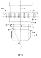
- Fig. 1 is a side elevational view of a first fastener according to an embodiment of the present invention
- Fig. 2 is side elevational view of a second fastener according to an embodiment of the present invention that includes an internal fluid passage;
- Fig. 3 is side elevational view, partly in section, of the fastener of Figure 1 mounted in a first bore;
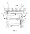
- Fig. 4 is a side elevation view, partly in section, of a fastener according to an embodiment of the present invention mounted in a second bore;
- Fig. 5 is a flow chart illustrating a method of forming a fastener according to an embodiment of the present invention.
- Fig. 6 is a side elevational view of a convention AS 1986 fluid fitting as it is inserted into a bore.
- Figure 1 illustrates a fastener 10 having a main body portion 12, a centerline 14, a sidewall 16, and an angled seating wall 18 extending from sidewall 16 to a shoulder 20 and making an angle ⁇ of about 20 degrees with centerline 14.
- a neck portion 24 having a diameter less than the diameter of main body portion 12 extends from shoulder 20 and terminates at a threaded end portion 26.
- a similar fastener 32 is illustrated in Figure 2 and is substantially identical to fastener 10 of Figure 1 except that fastener 32 includes a central bore 33 for allowing the flow of fluid therethrough. When fasteners are used for carrying fluid, they will generally include an O-ring (not shown) surrounding the neck portion of the fastener for improved sealing.
- the seating diameter is the diameter of fitting 10 at the narrowest point on seating wall 18 that is intended to make contact with the seat of a bore.
- the proximal contact point P is the part of threaded end portion 26 closest to shoulder 20 that is intended to engage the threaded portion of a bore. Portions of threaded end portion 26 closer to shoulder 20 will not engage the threaded portion of a bore.
- the circle (not shown) on the seating wall 18 that includes both ends of the seating diameter may be referred to herein as the "seating circumference.”
- the clamped length L is the distance between the plane of the seating circumference and proximal contact point P in the direction of centerline 14.
- Fastener 10 is configured for use in a bore such as bore 30 in a block 32 as illustrated in the fastening system of Figure 3.
- Bore 30 includes an angled seat 34 and a threaded portion 36. While threaded portion 36 of bore 30 is shown as comprising a female thread and threaded portion 26 of fastener 10 has a male thread, it is noted that these thread types could be reversed without exceeding the scope of the invention.
- the seating diameter will frequently be the diameter of seating wall 18 at shoulder 20 because the point at which seating wall 18 meets shoulder 20 will often be located at the innermost edge of a bore seat, such as bore seat 34, as illustrated in Figure 3.
- the clamped length L will frequently be the distance between shoulder 20 and the beginning of bore threaded portion 36 because the threaded portion 26 of fastener 10 will often be inserted fully into bore threaded portion 36 of bore 30.
- L and D can be calculated from either fastener 10 or bore 30.
- a fastener 40 includes a main body portion 42, a centerline 44, a sidewall 46, and an angled seating wall 48 extending from sidewall 46 to a shoulder 50 and making an angle ⁇ of about 20 degrees with centerline 44.
- a neck portion 54 having a diameter less than the diameter of main body portion 42 extends from shoulder 50 and terminates at a threaded end portion 56.
- Fastener 40 is shown positioned in a bore 60 in a block 62. Bore 60 includes an angled seat 64 and a threaded portion 66.
- Fastener 40 is designed such that a portion of seating wall 48 may extend into bore 60 past bore seat 64 and/or such that fastener end portion 56 does not fully overlap bore threaded portion 66. Both of these conditions are shown in Figure 4 for illustration purposes; however, both conditions will not always occur together. In this situation, the seating diameter D is different than the diameter of the seating surface at the fitting shoulder 50 and the clamped length L of the fitting is not measured from the end of threaded end portion 56 that is closest to shoulder 50 because proximal contact point P is not located at the end of threaded end portion 56.
- ⁇ arctan (D/(2L)).
- ⁇ may be based on the equipment used to form a bore and D may be based on a required fluid carrying capacity. In such cases, it becomes relatively easy to change L by changing the length of the neck portion of the fastener.
- ⁇ arctan (D/(2L)
- an embodiment of the present invention comprise a method of forming a fastener having an axial centerline and a seating surface angled with respect to the axial centerline at an angle ⁇ and adapted to contact an angled seat of a bore.
- the smallest diameter of the seating surface is called the seating diameter.
- the fastener includes a threaded connecting portion for engaging a threaded portion of a bore, the threaded connecting portion includes a point designated a proximal contact point, and the distance from the seating diameter to the proximal contact point in the direction of the axial centerline is designated the clamped length of the fastener.
Landscapes
- Engineering & Computer Science (AREA)
- General Engineering & Computer Science (AREA)
- Mechanical Engineering (AREA)
- Joints With Pressure Members (AREA)
Abstract
Description
- The present application claims the benefit of
U.S. Provisional Patent Application No. 60/815,587, filed June 22, 2006 - The present invention is directed toward a method of forming a fastener such that preload on the fastener varies in a desired manner with changing temperature and to a fastener formed by this method, and, more specifically, toward a method of selecting a relationship between various angles and dimensions of a fastener so that preload on the fastener will vary in a desired manner with changing temperature and toward a fastener having the selected relationship.
- "Rosan" style or AS 1986 fittings and similar fittings are commonly used in aerospace applications, to connect fluid lines to a block or body, for example. A first end of the fitting is attached to a fluid line and the second end is placed into a bore in the body and secured thereto in a well-known manner. As illustrated in Figure 6, these fittings may take the form of a fitting 200 having a
main body portion 201 having anaxial centerline 202, aseating surface 204 angled at an angle α relative toaxial centerline 202 and extending between asidewall 203 and ashoulder 205, aneck 206 projecting fromshoulder 205, and a threadedend portion 208. Such fittings also generally include aninternal bore 209 for carrying a fluid and an O-ring (not shown) surrounding at least a portion ofneck 206 to better seal the fitting. - The fittings may be placed into bores, such as
bore 210, which includes abore seat 212 and a threadedportion 214 complementary to the threads of the threadedend portion 208 of fitting 200. In use, the threadedend portion 208 of the fitting is inserted intobore 210 until it reaches threadedportion 214 ofbore 210. Fitting 200 is then rotated to threadedly engage threadedend portion 208 and borethreads 214 and draw fitting 200 intobore 210. This action movesseating surface 204 of fitting 200 toward and ultimately into contact withbore seat 212. Afterseating surface 204 contacts boreseat 212, a user continues to apply torque to fitting 200 until a desired preload is attained. Fluid fittings having this form are generally known; fittings without internal bores could alternately be provided to perform connecting or joining functions without carrying a fluid. As used herein, the term "fastener" includes versions of the fitting described above both with and without internal bores. - The bore into which a fastener is inserted is frequently formed in a material (such as aluminum) different than the material used to form the fastener (such as titanium). These materials have different coefficients of thermal expansion, and thus the preload on current fasteners tends to decrease with increasing temperature due to axial slip at the angled seating surface. A reduced preload at elevated operating temperatures and/or repeated changes to the preload may lead to premature fatigue failure of the fitting or the threads. It might be possible to address this problem by carefully matching the thermal properties of the fastener and the block. However, for various reasons, including cost and performance, this is often not possible or practical. It would therefore be desirable to control the preload on a fastener so that the preload remains substantially constant with changing temperature or varies with changing temperature in a desired manner.
- These and other problems are addressed by the present invention which comprises, in a first embodiment, a method of forming a fastener having an axial centerline and a seating surface angled with respect to the axial centerline at an angle α that is adapted to contact an angled seat of a bore. The smallest diameter of the seating surface may be called the seating diameter. The fastener also includes a threaded connecting portion for engaging a threaded portion of a bore, and this connecting portion includes a point designated a proximal contact point. The distance from the seating diameter to the proximal contact point in the direction of the axial centerline is designated the clamped length of the fastener. The method includes steps of determining a value for at least a first one of angle α, seating diameter D and clamped length L, solving the equation α = arctan (D/(2L)) to calculate at least a second one of angle α, seating diameter D and clamped length L, and forming a fastener based on the determined and calculated values.
- Another aspect of the invention comprises a fastener system that includes a block and a fastener. The block includes a bore having a diameter D, an angled seat at one end of the bore, and a threaded portion. The fastener has an axial centerline and a seating surface angled with respect to the axial centerline at an angle α, and the seating surface contacts the angled seat of the block. The fastener also includes a threaded connecting portion spaced from the seating surface and threadedly engaging the threaded bore portion, and a clamped portion that is the portion of the fastener between but not directly engaging the bore threaded portion and the bore angle seat, the clamped portion having a length L. In this fastener system, α is greater than or equal to arctan (D/(2L)) when a coefficient of thermal expansion of the block is greater than a coefficient of thermal expansion of the fastener and wherein α is less than or equal to arctan (D/(2L)) when a coefficient of thermal expansion of the block is less than a coefficient of thermal expansion of the fastener.
- A further aspect of the invention comprises a fastener that has an axial centerline and a seating surface angled with respect to the axial centerline at an angle α and adapted to contact an angled seat of a bore, where the smallest diameter of the seating surface comprises a seating diameter. The fastener also includes a threaded connecting portion for engaging a threaded portion of a bore, the threaded connecting portion including a point designated a proximal contact point, the distance from the seating diameter to the proximal contact point in the direction of the axial centerline comprising a clamped length of the fastener. In this fastener α is equal to arctan (D/(2L)).
- Fig. 1 is a side elevational view of a first fastener according to an embodiment of the present invention;
- Fig. 2 is side elevational view of a second fastener according to an embodiment of the present invention that includes an internal fluid passage;
- Fig. 3 is side elevational view, partly in section, of the fastener of Figure 1 mounted in a first bore;
- Fig. 4 is a side elevation view, partly in section, of a fastener according to an embodiment of the present invention mounted in a second bore;
- Fig. 5 is a flow chart illustrating a method of forming a fastener according to an embodiment of the present invention; and
- Fig. 6 is a side elevational view of a convention AS 1986 fluid fitting as it is inserted into a bore.
- Referring now to the drawings, wherein the showings are for purposes of illustrating preferred embodiments of the invention only and not for the purpose of limiting same, and wherein the showings are not necessarily to scale, Figure 1 illustrates a
fastener 10 having amain body portion 12, acenterline 14, asidewall 16, and anangled seating wall 18 extending fromsidewall 16 to ashoulder 20 and making an angle α of about 20 degrees withcenterline 14. Aneck portion 24 having a diameter less than the diameter ofmain body portion 12 extends fromshoulder 20 and terminates at a threadedend portion 26. Asimilar fastener 32 is illustrated in Figure 2 and is substantially identical tofastener 10 of Figure 1 except thatfastener 32 includes acentral bore 33 for allowing the flow of fluid therethrough. When fasteners are used for carrying fluid, they will generally include an O-ring (not shown) surrounding the neck portion of the fastener for improved sealing. - Referring again to Figure 1, two dimensions of
fastener 10 are referred to as a "seating diameter" D and a "clamped length" L, and a particular location on threadedend portion 26 is referred to as the "proximal contact point" P. The seating diameter is the diameter of fitting 10 at the narrowest point onseating wall 18 that is intended to make contact with the seat of a bore. The proximal contact point P is the part of threadedend portion 26 closest toshoulder 20 that is intended to engage the threaded portion of a bore. Portions of threadedend portion 26 closer toshoulder 20 will not engage the threaded portion of a bore. The circle (not shown) on theseating wall 18 that includes both ends of the seating diameter may be referred to herein as the "seating circumference." The clamped length L is the distance between the plane of the seating circumference and proximal contact point P in the direction ofcenterline 14. - Fastener 10 is configured for use in a bore such as bore 30 in a
block 32 as illustrated in the fastening system of Figure 3. Bore 30 includes anangled seat 34 and a threadedportion 36. While threadedportion 36 ofbore 30 is shown as comprising a female thread and threadedportion 26 offastener 10 has a male thread, it is noted that these thread types could be reversed without exceeding the scope of the invention. - The seating diameter will frequently be the diameter of
seating wall 18 atshoulder 20 because the point at whichseating wall 18 meetsshoulder 20 will often be located at the innermost edge of a bore seat, such asbore seat 34, as illustrated in Figure 3. The clamped length L will frequently be the distance betweenshoulder 20 and the beginning of bore threadedportion 36 because the threadedportion 26 offastener 10 will often be inserted fully into bore threadedportion 36 ofbore 30. For this specific case, L and D can be calculated from eitherfastener 10 or bore 30. - However, a more general case is illustrated Figure 4 wherein the above-mentioned conditions do not necessarily obtain. In this fastener system, a
fastener 40 includes amain body portion 42, acenterline 44, asidewall 46, and anangled seating wall 48 extending fromsidewall 46 to ashoulder 50 and making an angle α of about 20 degrees withcenterline 44. Aneck portion 54 having a diameter less than the diameter ofmain body portion 42 extends fromshoulder 50 and terminates at a threadedend portion 56.Fastener 40 is shown positioned in abore 60 in ablock 62. Bore 60 includes anangled seat 64 and a threadedportion 66. - Fastener 40 is designed such that a portion of
seating wall 48 may extend intobore 60past bore seat 64 and/or such thatfastener end portion 56 does not fully overlap bore threadedportion 66. Both of these conditions are shown in Figure 4 for illustration purposes; however, both conditions will not always occur together. In this situation, the seating diameter D is different than the diameter of the seating surface at thefitting shoulder 50 and the clamped length L of the fitting is not measured from the end of threadedend portion 56 that is closest toshoulder 50 because proximal contact point P is not located at the end of threadedend portion 56. - It has been found that forming a fastener with a certain relationship between α, D and L will cause the preload on
fastener 10 to be substantially independent of temperature. Specifically, when α is equal to arctan (D/(2L)), the preload should remain substantially constant with varying temperature. Of course, typical manufacturing tolerances may prevent the above equation from being satisfied exactly. However, even when one or more of the values α, D and L varies, for example, by 1 to 5 percent from ideal, the temperature-based variations in preload will beneficially be reduced. This effect is independent of the materials used for the block and the fastener. - One or two of the values α, D and L will be often be determined by design requirements or existing equipment. When two of these values are predetermined, the third value can be calculated from α = arctan (D/(2L)). For example, α may be based on the equipment used to form a bore and D may be based on a required fluid carrying capacity. In such cases, it becomes relatively easy to change L by changing the length of the neck portion of the fastener. While this may sometimes require a change of the position of the threaded portion of the bore, it may also be possible to make the threaded portion of a bore longer than the threaded end of the fastener so that the fastener can be inserted in the bore over a range of positions to obtain a wide range of desired clamped lengths L. Of course, when only one of the above values is predetermined, the above equation can be solved for one of the remaining variables in terms of the third variable.
- As one example, a typical value for α is 20 degrees. Therefore, based on the equation α = arctan (D/(2L)),
-

-

-

-

-

- Since L is often the most practical dimension to vary, a fastener can be formed having a clamped length based on the above calculations. When varying α using the above formula, it should be noted that as L/D decreases, as it tends to do for larger diameter fasteners (such as AS 1986 fasteners), the angle of the seating surface becomes "flatter" (a larger α).
- While it is often desirable to minimize changes in preload, it is also possible using embodiments of the present invention to ensure preload increases with temperature. First it must be determined whether the coefficient of thermal expansion of the fastener is greater than or less than that of the material that will receive the fastener. If the coefficient of thermal expansion of the fastener is less than that of the block of material, the fastener should be formed so that α > arctan (D/(2L)). If the coefficient of thermal expansion of the fastener is greater than that of the block of material, the fastener should be formed so that α < arctan (D/(2L)).
- As illustrated in Figure 5, an embodiment of the present invention comprise a method of forming a fastener having an axial centerline and a seating surface angled with respect to the axial centerline at an angle α and adapted to contact an angled seat of a bore. The smallest diameter of the seating surface is called the seating diameter. The fastener includes a threaded connecting portion for engaging a threaded portion of a bore, the threaded connecting portion includes a point designated a proximal contact point, and the distance from the seating diameter to the proximal contact point in the direction of the axial centerline is designated the clamped length of the fastener. The method includes a
step 100 of determining a value for at least a first one of angle α, seating diameter D and clamped length L, astep 102 of solving the equation α = arctan (D/(2L)) to calculate at least a second one of angle α, seating diameter D and clamped length L, and a step 104 of forming a fastener based on the determined and calculated values. - The present invention has been described above in terms of preferred embodiments. However, modifications and additions to these embodiments will become apparent to those of ordinary skill in the art upon a reading of the foregoing description. It is intended that all such obvious variations form a part of the present invention to the extent they fall within the scope of the several claims appended hereto.
Claims (9)
- A method of forming a fastener having:an axial centerline (14, 44);a seating surface (18, 48) angled with respect to the axial centerline (14, 44) at an angle α and adapted to contact an angled seat (34, 64) of a bore (30, 60), the smallest diameter of the seating surface (18, 48) comprising a seating diameter (D); anda threaded connecting portion (26, 56) for engaging a threaded portion of a bore (36, 66), the threaded connecting portion (26, 56) including a proximal contact point (P), the distance from the seating diameter (D) to the proximal contact point (P) in the direction of the axial centerline (14, 44) being the clamped length (L) of the fastener;said method comprising the steps of:determining a value for at least a first one of angle α, seating diameter D and clamped length L;solving the equation α = (D/(2L)) to calculate at least a second one of angle α, seating diameter D and clamped length L; andforming a fastener based on the determined and calculated values.
- The method of claim 1 wherein said step of forming a fastener based on the determined and calculated values comprises the step of forming a fastener having the determined and calculated values for angle α, seating diameter D and clamped length L.
- The method of claim 1 wherein said step of forming a fastener based on the determined and calculated values comprises the steps of:determining whether a fastener preload should vary directly or inversely with temperature;determining whether a coefficient of thermal expansion of a material having a bore for receiving the fastener is greater than or less than a coefficient of thermal expansion of the fastener;changing the calculated at least second one of angle α, seating diameter D and clamped length L such that:α is greater than arctan (D/(2L)) if it is determined that fastener preload should vary directly with changing temperature and the coefficient of thermal expansion of the material is greater than the coefficient of thermal expansion of the fastener;α is less than arctan (D/(2L)) if it is determined that fastener preload should vary directly with changing temperature and the coefficient of thermal expansion of the material is less than the coefficient of thermal expansion of the fastener;α is less than arctan (D/(2L)) if it is determined that fastener preload should vary inversely with changing temperature and the coefficient of thermal expansion of the material is greater than the coefficient of thermal expansion of the fastener; andα is greater than arctan (D/(2L)) if it is determined that fastener preload should vary inversely with changing temperature and the coefficient of thermal expansion of the material is less than the coefficient of thermal expansion of the fastener.
- A fastener system comprising:a block (32, 62) comprising a bore (30, 60), said bore (30, 60) having a diameter D, an angled seat (34, 64) at one end of the bore (30, 60), and a threaded portion (36, 66);a fastener (10, 32, 40) having an axial centerline (14, 44), a seating surface (18, 48) angled with respect to the axial centerline (14, 44) at an angle α, said seating surface (18, 48) contacting the angled seat (34, 64) of the block (32, 62), a threaded connecting portion (26, 56) spaced from the seating surface (18, 48) and threadedly engaging the threaded bore portion (36, 66), and a clamped portion comprising the portion of the fastener (10, 32, 40) between but not directly engaging said bore threaded portion (36, 66) and said bore angled seat (34, 64), said clamped portion having a length L,wherein α is greater than or equal to arctan (D/(2L)) when a coefficient of thermal expansion of the block is greater than a coefficient of thermal expansion of the fastener, andwherein α is less than or equal to arctan (D/(2L)) when a coefficient of thermal expansion of the block is less than a coefficient of thermal expansion of the fastener.
- The fastener system of claim 4 wherein α is approximately equal to arctan (D/(2L)).
- The fastener system of claim 4 wherein said fastener includes a central bore (33) communicating with said block bore (30, 60).
- The fastener system of claim 4 wherein said fastener seating surface (18, 48) is spaced from the connecting portion (26, 56) by a neck (24, 54) having a diameter less than the diameter of connecting portion (26, 56).
- A fastener comprising:an axial centerline (14, 44);a seating surface (18, 48) angled with respect to the axial centerline (14, 44) at an angle α and adapted to contact an angled seat (34, 64) of a bore (30, 60), the smallest diameter of the seating surface (18, 48) comprising the seating diameter (D); anda threaded connecting portion (26, 56) for engaging a threaded portion (36, 66) of a bore, the threaded connecting portion (26, 56) including a proximal contact point (P), the distance from the seating diameter (D) to the proximal contact point (P) in the direction of the axial centerline (14, 44) comprising a clamped length (L) of the fastener;wherein α, D and L satisfy the equation α = arctan (D/(2L)).
- The fastener of claim 8 wherein said fastener seating surface (18, 48) is spaced from the connecting portion (26, 56) by a neck (24, 54) having a diameter less than the diameter of connecting portion (26, 56).
Applications Claiming Priority (2)
| Application Number | Priority Date | Filing Date | Title |
|---|---|---|---|
| US81558706P | 2006-06-22 | 2006-06-22 | |
| US11/698,124 US7896600B2 (en) | 2006-06-22 | 2007-01-26 | Fastener having controllably variable preload and method of forming same |
Publications (1)
| Publication Number | Publication Date |
|---|---|
| EP1870603A1 true EP1870603A1 (en) | 2007-12-26 |
Family
ID=38441513
Family Applications (1)
| Application Number | Title | Priority Date | Filing Date |
|---|---|---|---|
| EP07110735A Withdrawn EP1870603A1 (en) | 2006-06-22 | 2007-06-21 | Fastener having controllably variable preload and method of forming same |
Country Status (2)
| Country | Link |
|---|---|
| US (2) | US7896600B2 (en) |
| EP (1) | EP1870603A1 (en) |
Families Citing this family (3)
| Publication number | Priority date | Publication date | Assignee | Title |
|---|---|---|---|---|
| JP5364045B2 (en) * | 2010-06-11 | 2013-12-11 | 川崎重工業株式会社 | Hydraulic equipment plugs |
| US11506238B2 (en) * | 2013-06-14 | 2022-11-22 | James Alan Monroe | Thermally stabilized fastener system and method |
| CN112800556A (en) * | 2021-01-27 | 2021-05-14 | 北京空天技术研究所 | Fastener and design method |
Citations (4)
| Publication number | Priority date | Publication date | Assignee | Title |
|---|---|---|---|---|
| GB693317A (en) * | 1951-03-13 | 1953-06-24 | Joseph Rosan | Improvements in or relating to threaded insert protector |
| GB2218174A (en) | 1988-04-23 | 1989-11-08 | Acme Marls Ltd | Connecting members with differing thermal expansion |
| US4934857A (en) * | 1987-06-26 | 1990-06-19 | General Dynamics Corporation, Convair Division | Co-conic fastener and fastening method |
| US6171009B1 (en) * | 1998-10-20 | 2001-01-09 | Lockheed Martin Corporation | Method and apparatus for temperature-stabilizing a joint |
Family Cites Families (19)
| Publication number | Priority date | Publication date | Assignee | Title |
|---|---|---|---|---|
| US2942895A (en) | 1956-07-13 | 1960-06-28 | L & L Mfg Company | Captive nut |
| US3106413A (en) | 1958-03-17 | 1963-10-08 | North American Aviation Inc | Pipe coupling having a static seal |
| US3145362A (en) * | 1961-01-04 | 1964-08-18 | Rosemount Eng Co Ltd | Electrical resistance device |
| US3395934A (en) * | 1965-10-22 | 1968-08-06 | Rosan Jose | Fittings for high pressure fluid lines |
| US3632143A (en) * | 1969-06-19 | 1972-01-04 | Westinghouse Electric Corp | Bimetallic coupling joint for tubes of dissimilar materials |
| US3611881A (en) * | 1970-04-13 | 1971-10-12 | Case Co J I | Fluid cylinder and piston assembly |
| US3730563A (en) | 1971-02-22 | 1973-05-01 | Mc Donnell Douglas Corp | Lip seal fitting |
| US3702707A (en) * | 1971-06-23 | 1972-11-14 | Jose Rosan Sr | Fittings for high pressure fluid lines |
| US4161967A (en) * | 1978-02-03 | 1979-07-24 | The Babcock & Wilcox Company | Thermal sleeve |
| DE2964587D1 (en) * | 1978-04-14 | 1983-03-03 | Pilkington Brothers Plc | A roll for use under high or low temperature conditions |
| US4191486A (en) * | 1978-09-06 | 1980-03-04 | Union Carbide Corporation | Threaded connections |
| EP0102161B1 (en) | 1982-08-18 | 1987-05-20 | Imperial Chemical Industries Plc | Coupling |
| US4553776A (en) | 1983-10-25 | 1985-11-19 | Shell Oil Company | Tubing connector |
| US4854613A (en) * | 1988-01-27 | 1989-08-08 | Rexnord Holdings Inc. | Composite connecting member for hydraulic fluid lines |
| US4934742A (en) * | 1988-01-27 | 1990-06-19 | Nwd International, Inc. | Hydraulic coupling |
| EP0609380B1 (en) | 1991-10-25 | 1997-06-18 | NWD International, Inc. | Hydraulic port fittings |
| US5573285A (en) | 1995-01-11 | 1996-11-12 | Universal Enterprises, Inc. | High-temperature, double-bead, tube-fitting assembly |
| DE19853803C1 (en) | 1998-11-21 | 2000-03-30 | Vaw Alucast Gmbh | Apparatus for producing an engine block with cast-in cylinder liners comprises conical seating surfaces which ensure that the ends of the cylinder liners undergoing thermal expansion remain pressed against them |
| US6375232B1 (en) | 2000-04-27 | 2002-04-23 | The Boeing Company | Bi-metallic union fitting for use in threaded ports |
-
2007
- 2007-01-26 US US11/698,124 patent/US7896600B2/en not_active Expired - Fee Related
- 2007-06-21 EP EP07110735A patent/EP1870603A1/en not_active Withdrawn
-
2011
- 2011-02-10 US US13/024,892 patent/US8439618B2/en not_active Expired - Fee Related
Patent Citations (4)
| Publication number | Priority date | Publication date | Assignee | Title |
|---|---|---|---|---|
| GB693317A (en) * | 1951-03-13 | 1953-06-24 | Joseph Rosan | Improvements in or relating to threaded insert protector |
| US4934857A (en) * | 1987-06-26 | 1990-06-19 | General Dynamics Corporation, Convair Division | Co-conic fastener and fastening method |
| GB2218174A (en) | 1988-04-23 | 1989-11-08 | Acme Marls Ltd | Connecting members with differing thermal expansion |
| US6171009B1 (en) * | 1998-10-20 | 2001-01-09 | Lockheed Martin Corporation | Method and apparatus for temperature-stabilizing a joint |
Also Published As
| Publication number | Publication date |
|---|---|
| US20070297872A1 (en) | 2007-12-27 |
| US8439618B2 (en) | 2013-05-14 |
| US20110188965A1 (en) | 2011-08-04 |
| US7896600B2 (en) | 2011-03-01 |
Similar Documents
| Publication | Publication Date | Title |
|---|---|---|
| EP2333299B1 (en) | Pipe fastening structure | |
| US6764107B1 (en) | Self-sealing pre-assembled endfitting/coupling for corrugated tubing | |
| EP2995840B1 (en) | Pipe connecting device | |
| KR102025242B1 (en) | Metal sealing threaded (tube-o) fitting | |
| EP2069646B1 (en) | Threaded fastener with predetermined torque | |
| EP2995839B1 (en) | Pipe connecting device | |
| CN102112793A (en) | Resinous tube joint | |
| CN105556190B (en) | The pipe joint made of synthetic resin | |
| US9599266B2 (en) | Externally sealing connector | |
| KR101945656B1 (en) | Threaded connection for pipes, such as oil and gas pipes | |
| US11009158B2 (en) | Conduit fitting with stroke resisting features | |
| US6991268B2 (en) | Pipe fitting having over-sized strengthened starter threads | |
| US8439618B2 (en) | Fastener having controllably variable preload and method of forming same | |
| AU2019100400C4 (en) | Plumbing Fitting | |
| EP1605196A1 (en) | Self-sealing pre-assembled endfitting/coupling for corrugated tubing | |
| JP5775911B2 (en) | Pipe fitting | |
| KR102343225B1 (en) | Thermal cycle resistant fastening system for refrigerant fitting | |
| JP6420882B2 (en) | Synthetic resin pipe fittings | |
| CN213236488U (en) | Measuring coupling | |
| US20230341070A1 (en) | Tapered thread connection sealing arrangements | |
| GB2406886A (en) | End fitting for tubular member | |
| CN120225804A (en) | Improved tubular assembly intended to be connected to a second conduit |
Legal Events
| Date | Code | Title | Description |
|---|---|---|---|
| PUAI | Public reference made under article 153(3) epc to a published international application that has entered the european phase |
Free format text: ORIGINAL CODE: 0009012 |
|
| AK | Designated contracting states |
Kind code of ref document: A1 Designated state(s): AT BE BG CH CY CZ DE DK EE ES FI FR GB GR HU IE IS IT LI LT LU LV MC MT NL PL PT RO SE SI SK TR |
|
| AX | Request for extension of the european patent |
Extension state: AL BA HR MK YU |
|
| 17P | Request for examination filed |
Effective date: 20080616 |
|
| 17Q | First examination report despatched |
Effective date: 20080721 |
|
| AKX | Designation fees paid |
Designated state(s): DE FR GB |
|
| GRAP | Despatch of communication of intention to grant a patent |
Free format text: ORIGINAL CODE: EPIDOSNIGR1 |
|
| STAA | Information on the status of an ep patent application or granted ep patent |
Free format text: STATUS: THE APPLICATION IS DEEMED TO BE WITHDRAWN |
|
| 18D | Application deemed to be withdrawn |
Effective date: 20100205 |