EP1870598A1 - Scroll compressor - Google Patents
Scroll compressor Download PDFInfo
- Publication number
- EP1870598A1 EP1870598A1 EP06712592A EP06712592A EP1870598A1 EP 1870598 A1 EP1870598 A1 EP 1870598A1 EP 06712592 A EP06712592 A EP 06712592A EP 06712592 A EP06712592 A EP 06712592A EP 1870598 A1 EP1870598 A1 EP 1870598A1
- Authority
- EP
- European Patent Office
- Prior art keywords
- scroll
- spiral tooth
- orbiting scroll
- spiral
- tip
- Prior art date
- Legal status (The legal status is an assumption and is not a legal conclusion. Google has not performed a legal analysis and makes no representation as to the accuracy of the status listed.)
- Granted
Links
Images



Classifications
-
- F—MECHANICAL ENGINEERING; LIGHTING; HEATING; WEAPONS; BLASTING
- F04—POSITIVE - DISPLACEMENT MACHINES FOR LIQUIDS; PUMPS FOR LIQUIDS OR ELASTIC FLUIDS
- F04C—ROTARY-PISTON, OR OSCILLATING-PISTON, POSITIVE-DISPLACEMENT MACHINES FOR LIQUIDS; ROTARY-PISTON, OR OSCILLATING-PISTON, POSITIVE-DISPLACEMENT PUMPS
- F04C27/00—Sealing arrangements in rotary-piston pumps specially adapted for elastic fluids
- F04C27/005—Axial sealings for working fluid
-
- F—MECHANICAL ENGINEERING; LIGHTING; HEATING; WEAPONS; BLASTING
- F04—POSITIVE - DISPLACEMENT MACHINES FOR LIQUIDS; PUMPS FOR LIQUIDS OR ELASTIC FLUIDS
- F04C—ROTARY-PISTON, OR OSCILLATING-PISTON, POSITIVE-DISPLACEMENT MACHINES FOR LIQUIDS; ROTARY-PISTON, OR OSCILLATING-PISTON, POSITIVE-DISPLACEMENT PUMPS
- F04C18/00—Rotary-piston pumps specially adapted for elastic fluids
- F04C18/02—Rotary-piston pumps specially adapted for elastic fluids of arcuate-engagement type, i.e. with circular translatory movement of co-operating members, each member having the same number of teeth or tooth-equivalents
- F04C18/0207—Rotary-piston pumps specially adapted for elastic fluids of arcuate-engagement type, i.e. with circular translatory movement of co-operating members, each member having the same number of teeth or tooth-equivalents both members having co-operating elements in spiral form
- F04C18/0215—Rotary-piston pumps specially adapted for elastic fluids of arcuate-engagement type, i.e. with circular translatory movement of co-operating members, each member having the same number of teeth or tooth-equivalents both members having co-operating elements in spiral form where only one member is moving
- F04C18/0223—Rotary-piston pumps specially adapted for elastic fluids of arcuate-engagement type, i.e. with circular translatory movement of co-operating members, each member having the same number of teeth or tooth-equivalents both members having co-operating elements in spiral form where only one member is moving with symmetrical double wraps
-
- F—MECHANICAL ENGINEERING; LIGHTING; HEATING; WEAPONS; BLASTING
- F04—POSITIVE - DISPLACEMENT MACHINES FOR LIQUIDS; PUMPS FOR LIQUIDS OR ELASTIC FLUIDS
- F04C—ROTARY-PISTON, OR OSCILLATING-PISTON, POSITIVE-DISPLACEMENT MACHINES FOR LIQUIDS; ROTARY-PISTON, OR OSCILLATING-PISTON, POSITIVE-DISPLACEMENT PUMPS
- F04C18/00—Rotary-piston pumps specially adapted for elastic fluids
- F04C18/02—Rotary-piston pumps specially adapted for elastic fluids of arcuate-engagement type, i.e. with circular translatory movement of co-operating members, each member having the same number of teeth or tooth-equivalents
- F04C18/0207—Rotary-piston pumps specially adapted for elastic fluids of arcuate-engagement type, i.e. with circular translatory movement of co-operating members, each member having the same number of teeth or tooth-equivalents both members having co-operating elements in spiral form
- F04C18/0246—Details concerning the involute wraps or their base, e.g. geometry
- F04C18/0269—Details concerning the involute wraps
- F04C18/0284—Details of the wrap tips
-
- F—MECHANICAL ENGINEERING; LIGHTING; HEATING; WEAPONS; BLASTING
- F04—POSITIVE - DISPLACEMENT MACHINES FOR LIQUIDS; PUMPS FOR LIQUIDS OR ELASTIC FLUIDS
- F04C—ROTARY-PISTON, OR OSCILLATING-PISTON, POSITIVE-DISPLACEMENT MACHINES FOR LIQUIDS; ROTARY-PISTON, OR OSCILLATING-PISTON, POSITIVE-DISPLACEMENT PUMPS
- F04C23/00—Combinations of two or more pumps, each being of rotary-piston or oscillating-piston type, specially adapted for elastic fluids; Pumping installations specially adapted for elastic fluids; Multi-stage pumps specially adapted for elastic fluids
- F04C23/008—Hermetic pumps
-
- F—MECHANICAL ENGINEERING; LIGHTING; HEATING; WEAPONS; BLASTING
- F04—POSITIVE - DISPLACEMENT MACHINES FOR LIQUIDS; PUMPS FOR LIQUIDS OR ELASTIC FLUIDS
- F04C—ROTARY-PISTON, OR OSCILLATING-PISTON, POSITIVE-DISPLACEMENT MACHINES FOR LIQUIDS; ROTARY-PISTON, OR OSCILLATING-PISTON, POSITIVE-DISPLACEMENT PUMPS
- F04C27/00—Sealing arrangements in rotary-piston pumps specially adapted for elastic fluids
- F04C27/001—Radial sealings for working fluid
-
- F—MECHANICAL ENGINEERING; LIGHTING; HEATING; WEAPONS; BLASTING
- F04—POSITIVE - DISPLACEMENT MACHINES FOR LIQUIDS; PUMPS FOR LIQUIDS OR ELASTIC FLUIDS
- F04C—ROTARY-PISTON, OR OSCILLATING-PISTON, POSITIVE-DISPLACEMENT MACHINES FOR LIQUIDS; ROTARY-PISTON, OR OSCILLATING-PISTON, POSITIVE-DISPLACEMENT PUMPS
- F04C27/00—Sealing arrangements in rotary-piston pumps specially adapted for elastic fluids
- F04C27/008—Sealing arrangements in rotary-piston pumps specially adapted for elastic fluids for other than working fluid, i.e. the sealing arrangements are not between working chambers of the machine
- F04C27/009—Shaft sealings specially adapted for pumps
-
- F—MECHANICAL ENGINEERING; LIGHTING; HEATING; WEAPONS; BLASTING
- F04—POSITIVE - DISPLACEMENT MACHINES FOR LIQUIDS; PUMPS FOR LIQUIDS OR ELASTIC FLUIDS
- F04C—ROTARY-PISTON, OR OSCILLATING-PISTON, POSITIVE-DISPLACEMENT MACHINES FOR LIQUIDS; ROTARY-PISTON, OR OSCILLATING-PISTON, POSITIVE-DISPLACEMENT PUMPS
- F04C2210/00—Fluid
- F04C2210/10—Fluid working
- F04C2210/1027—CO2
-
- F—MECHANICAL ENGINEERING; LIGHTING; HEATING; WEAPONS; BLASTING
- F04—POSITIVE - DISPLACEMENT MACHINES FOR LIQUIDS; PUMPS FOR LIQUIDS OR ELASTIC FLUIDS
- F04C—ROTARY-PISTON, OR OSCILLATING-PISTON, POSITIVE-DISPLACEMENT MACHINES FOR LIQUIDS; ROTARY-PISTON, OR OSCILLATING-PISTON, POSITIVE-DISPLACEMENT PUMPS
- F04C2210/00—Fluid
- F04C2210/10—Fluid working
- F04C2210/1072—Oxygen (O2)
Definitions
- the present invention relates to a scroll compressor in which spiral teeth are formed on two surfaces of an orbiting scroll, and relates particularly to a technique that reduces leakage loss in a scroll compressor.
- a scroll compressor is a configuration constituted by: an orbiting scroll having spiral teeth formed on two sides; and a pair of fixed scrolls on which spiral teeth are formed such that the respective spiral teeth intermesh (see Patent Literature 1, for example).
- this will be called a "double-sided spiral scroll compressor”.
- double-sided spiral scroll compressors of this kind axial thrust loads due to compressed gas cancel each other out because compression chambers are formed on both sides of the orbiting scroll.
- tip seals are divided into two sections vertically and mating surfaces thereof are formed so as to have a saw-teeth form in order to suppress leakage from the spiral tooth tip end gaps (see Patent Literature 3, for example).
- suppression of leakage is achieved by upper tip seals being raised onto lower tip seals by pressure differences to fill the spiral tooth tip end gaps.
- the present invention aims to solve the above problems and an object of the present invention is to provide a scroll compressor that has reduced leakage loss and high efficiency.
- a scroll compressor including: an orbiting scroll that has spiral teeth on two surfaces; and a pair of fixed scrolls that are installed so as to face the surfaces of the orbiting scroll and that have spiral teeth that intermesh with the spiral teeth of the orbiting scroll, characterized in that tip seals are mounted only to a spiral tooth of the fixed scroll that intermeshes with a first spiral tooth of the orbiting scroll and to the first spiral tooth of the orbiting scroll.
- an orbiting scroll that has spiral teeth on two surfaces, and a pair of fixed scrolls that are installed so as to face the surfaces of the orbiting scroll and that have spiral teeth that intermesh with the spiral teeth of the orbiting scroll are included, and tip seals are mounted only to a spiral tooth of the fixed scroll that intermeshes with a first spiral tooth of the orbiting scroll and to the first spiral tooth of the orbiting scroll, a scroll compressor that has reduced leakage loss and high efficiency can be provided.
- Figure 1 is a cross section showing a configuration of a double-sided spiral scroll compressor according to Embodiment 1 of the present invention.
- a motor 2 is disposed in an upper portion inside a vertical sealed vessel 1, and a compression portion 3 is disposed below the motor 2.
- a lubricating oil storage chamber 4 for storing lubricating oil 41 is formed further below the compression portion 3.
- a suction pipe 5 for sucking in gas is disposed on a side surface of the sealed vessel 1 at an intermediate portion between the motor 2 and the compression portion 3, and a discharge pipe 8 for discharging compressed gas is disposed on the compression portion 3.
- a glass terminal 6 for supplying electric power is disposed on an upper end of the sealed vessel 1.
- the motor 2 is constituted by: a stator 21 that is formed so as to have a ring shape; and a rotor 22 that is supported inside the stator 21 so as to be rotatable.
- a main shaft 7 is fixed to the rotor 22 and passes through the compression portion 3, and an end portion of the main shaft 7 is immersed in the lubricating oil 41 in the lubricating oil storage chamber 4.
- the compression portion 3 has: an orbiting scroll 31; an upper fixed scroll 33 and a lower fixed scroll 34 that are installed so as to face two surfaces of the orbiting scroll 31; and a commonly-known Oldham coupling 35 that is disposed between the lower fixed scroll 34 and the orbiting scroll 31.
- An upper spiral tooth 31L and a lower spiral tooth 31M are disposed on two surfaces of a base plate 31B of the orbiting scroll 31 so as to be symmetrical and also equal in height to each other.
- a spiral tooth 33E is disposed on a surface of a base plate 33A of the upper fixed scroll 33 that faces the orbiting scroll 31 so as to intermesh with the upper spiral tooth 31L of the orbiting scroll 31, and the upper spiral tooth 31L of the orbiting scroll 31 and the spiral tooth 33E of the upper fixed scroll 33 form an upper compression chamber 32A.
- a spiral tooth 34E is disposed on a surface of a base plate 34A of the lower fixed scroll 34 that faces the orbiting scroll 31 so as to intermesh with the lower spiral tooth 31M of the orbiting scroll 31, and the lower spiral tooth 31M of the orbiting scroll 31 and the spiral tooth 34E of the lower fixed scroll 34 form a lower compression chamber 32B.
- Tip seals 36 are mounted to a tip end surface of the upper spiral tooth 31L of the orbiting scroll 31 and a tip end surface of the spiral tooth 33E of the upper fixed scroll 33. Seal rings 37 are also disposed inside the upper spiral tooth 31L and the lower spiral tooth 31M, respectively, of the orbiting scroll 31 outside the main shaft 7.
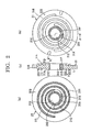
- Figure 2 is a diagram explaining a configuration of an orbiting scroll according to Embodiment 1, Figure 2(a) being a top plan of the orbiting scroll, Figure 2(b) being a bottom plan of the orbiting scroll, and Figure 2(c) being a cross section taken along line A - A in Figure 2(b).
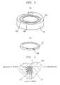
- Figure 3 is a diagram explaining a configuration of a bulb portion that is positioned at a central portion of the orbiting scroll, Figure 3(a) being a perspective showing the shape of the bulb portion, and Figure 3(b) being a perspective showing a configuration of seal rings that are installed on an upper surface and a lower surface of the bulb portion.
- Detailed configuration of the orbiting scroll 31 will now be explained.
- the orbiting scroll 31 has: a bulb portion 31A that constitutes a central portion and is constituted by curves such as arcs, etc.; and a disk-shaped base plate 31B that extends outside the bulb portion 31A.
- the upper spiral tooth 31L and the lower spiral tooth 31M which are symmetrical and are approximately equal in height to the bulb portion 31A, are formed on an upper surface and a lower surface of the base plate 31B by involute curves or arcs.
- “symmetrical” means configured such that thickness t, height h, pitch p, and number of turns n of the spiral teeth are all equal.
- a tip seal groove 31H for mounting a tip seal 36 is formed on the tip end surface of the upper spiral tooth 31L.
- a tip seal groove 31H for mounting a tip seal 36 is not formed on the tip end surface of the lower spiral tooth 31M.
- a main shaft aperture 31C through which the main shaft 7 passes is formed on a central portion of the bulb portion 31A, and an orbiting shaft bearing 31D is disposed on an inner wall thereof.
- An upper seal ring groove 31E and a lower seal ring groove 31F are formed on an outer portion of the orbiting shaft bearing 31D on the upper surface and the lower surface, respectively, of the bulb portion A, and seal rings 37 having an abutted joint 37A as shown in Figure 3(b) are installed in the upper seal ring groove 31E and the lower seal ring groove 31F.
- a communicating port 31K that connects the upper compression chamber 32A and the lower compression chamber 32B is disposed outside the bulb portion 31A.
- Figure 4 is a cross section in which a vicinity of a seal ring is enlarged in order to explain effects of a contact sealing action of the seal rings.
- the seal ring 37 is pressed from the left and from below, which are on a high-pressure side, as indicated by the arrows, due to differential pressure on two sides of the compression chamber that are partitioned off. For this reason, the seal ring 37 is pressed against a wall to the right of the seal ring groove 31E and the base plate 33A of the fixed scroll 33 above inside the seal ring groove 31E, forming a contact seal between the orbiting scroll 31 and the upper fixed scroll 33.
- Contact sealing actions of the seal ring 37 are also similar on the lower surface of the orbiting scroll 31, that is, between the orbiting scroll 31 and the lower fixed scroll 34.
- a communicating port 31K that merges gas compressed in the upper compression chamber 32A and the lower compression chamber 32B and directs it toward a discharge port 34F on the lower fixed scroll 34 is disposed on the orbiting scroll 31 as shown in Figure 2.
- the communicating port 31K is formed so as to pass vertically through the base plate 31B outside the upper seal ring groove 31E and the lower seal ring groove 31F.
- the communicating port 31K is disposed at a position where it does not span the partitioned compression chambers in the upper spiral tooth 31L or the lower spiral tooth 31M and where it always communicates with the discharge port 34F that is disposed on the lower fixed scroll 34 even during orbital motion.
- Figure 5 is a diagram explaining a configuration of a lower fixed scroll, Figure 5(a) being a top plan, and Figure 5(b) being a cross section taken along line A - A in Figure 5(a). Configuration of the lower fixed scroll 34 will now be explained.
- a main shaft aperture 34B through which the main shaft 7 passes is formed on a central portion of the base plate 34A of the lower fixed scroll 34, and a main shaft bearing 34C is disposed on an inner surface of the main shaft aperture 34B.
- a recess portion 34D that accommodates the bulb portion 31A of the orbiting scroll 31 and permits orbital motion of the orbiting scroll 31 is formed on an upper surface of the lower fixed scroll 34 at an outer portion of the main shaft bearing 34C.
- a spiral tooth 34E that has a thickness t, a height h, a pitch p, and number of turns n identical to those of the lower spiral tooth 31M of the orbiting scroll 31 and has a phase rotated by 180 degrees is formed outside the recess portion 34D.
- a discharge port 34F for discharging compressed gas is disposed in the recess portion 34D at a position where it does not face the seal ring 37 that is installed on the orbiting scroll 31 and where it always communicates with the communicating port 31K of the orbiting scroll 31.
- a discharge flow channel 34G that communicates with the discharge port 34F and directs compressed gas to the discharge pipe 8 disposed on the sealed vessel 1 is formed on the lower fixed scroll 34, and a discharge valve 34H for preventing reverse flow of gas is disposed inside the discharge flow channel 34G at a position facing the discharge port 34F.
- a suction port 34J that sucks gas into the lower compression chamber 32B is disposed on an outermost portion of the lower fixed scroll 34.
- Figure 6 is a cross section in which a central vicinity of the orbiting scroll of the scroll compressor according to Embodiment 1 is enlarged.
- a main shaft aperture 33B through which the main shaft 7 passes is formed on a central portion of the base plate 33A of the upper fixed scroll 33 in a similar manner to the lower fixed scroll 34 shown in Figure 5, and a main shaft bearing 33C is disposed on an inner surface of the main shaft aperture 33B.
- a slider 38 that is fitted onto the main shaft 7 is disposed between the orbiting shaft bearing 31D and the main shaft 7 and, together with the main shaft 7, constitutes an eccentric shaft that drives the orbiting scroll 31 by means of the orbiting shaft bearing 31D.
- Tip seal grooves 31H and 33H are formed on a tip end surface of the upper spiral tooth 31L of the orbiting scroll 31 and a tip end surface of the spiral tooth 33E of the upper fixed scroll 33, respectively, and tip seals 36 are mounted into each of the tip seal grooves 31H and 33H.
- tip seal grooves are not formed and tip seals 36 are not mounted to a tip end surface of the lower spiral tooth 31M of the orbiting scroll 31 or to a tip end surface of the spiral tooth 34E of the lower fixed scroll 34.
- gas that is sucked inside the sealed vessel 1 through the suction pipe 5 flows into a portion where the motor 2 is installed, and cools the motor 2.
- the gas that has been sucked in is introduced through a suction port 33J that is disposed on an outer portion of the upper fixed scroll 33 into the upper compression chamber 32A and the lower compression chamber 32B that are formed on the two surfaces of the orbiting scroll 31 as indicated by arrows.
- the orbiting scroll 31 orbits relative to the upper fixed scroll 33 and the lower fixed scroll 34 without autorotating, such that the volumes of the crescent-shaped upper compression chamber 32A and lower compression chamber 32B that are formed are gradually reduced toward the center, and the gas is compressed by a commonly-known compression principle.
- the gas compressed in the upper compression chamber 32A and the lower compression chamber 32B, respectively, merges at the discharge port 34F, passes through the discharge flow channel 34G, and flows out of the sealed vessel 1 through the discharge pipe 8.
- FIG. 7 is a schematic diagram for explaining the thrust loads that act on the orbiting scroll 31.
- the tip seal 36 exhibits behavior similar to that of the seal ring 37 shown in Figure 4, and is pushed from a high-pressure side toward a low-pressure side by differential pressure between compression chambers that are partitioned off on both sides. If we assume that the right side of the upper spiral tooth 31L in Figure 7 is the high-pressure side (pressure P 1 ), and the left side is the low-pressure side (pressure P 2 ), then the tip seal 36 is pressed from the right and from below, and forms a contact seal inside the tip seal groove 31H by being pressed against a wall of the tip seal groove 31H on the left and the base plate 33A above.
- the pressure P 1 on the high-pressure side acts on a bottom surface of the tip seal groove 31H of the orbiting scroll 31 and a spiral tooth inner tip end surface
- the pressure P 2 on the low-pressure side acts on a spiral tooth outer tip end surface
- the thrust load F that acts on the orbiting scroll 31 will now be explained. Because the pressure that acts on the upper surface and the pressure that acts on the lower surface are equal in portions of the base plate 31B where there is no upper spiral tooth 31L and no lower spiral tooth 31M, the thrust loads cancel each other out.
- thrust load F 1 that acts on the tip end surface of the upper spiral tooth 31L and the thrust load F 2 per unit length that acts on the tip end surface of the lower spiral tooth 31M differ from each other. If we let overall thickness of the upper spiral tooth 31L and the lower spiral tooth 31M be t, and width of the outer tip end surface of the upper spiral tooth 31L be t 12 , then thrust load per unit length F 1 that acts on the tip end surface of the upper spiral tooth 31L can be expressed by Mathematical Formula 1.
- thrust load per unit length F 2 that acts on the tip end surface of the lower spiral tooth 31M can be expressed by Mathematical Formula 2.
- the tip seals 36 are mounted to the upper spiral tooth 31L and the lower spiral tooth 31M of the orbiting scroll 31, to the spiral tooth 33E of the upper fixed scroll 33, and to the spiral tooth 34E of the lower fixed scroll 34, leakage occurs on the two surfaces of the orbiting scroll 31 in directions parallel to the upper spiral tooth 31L and the lower spiral tooth 31M, respectively. Consequently, leakage in directions parallel to the spiral teeth can be reduced if the tip seals 36 are mounted only to the upper spiral tooth 31L and the spiral tooth 33E of the upper fixed scroll 33 compared to when the tip seals 36 are mounted to all of the spiral tooth 31L, 31M, 33E, and 34E.
- Figure 8 is a schematic diagram for explaining thrust loads that act on a tip seal.
- the contact load per unit length on a spiral tooth to which a tip seal is mounted is a contact load per unit length F C of the tip seal 36 relative to the base plate 33A.
- a thrust load per unit length F 4 that pushes the tip seal 36 downward can be expressed by Mathematical Formula 6.
- a double-sided spiral scroll compressor according to the present invention and the double-sided spiral scroll compressor that is disclosed as a conventional example in Patent Literature 3 will now be compared.
- tip seals are divided into two sections vertically and mating surfaces thereof are formed so as to have a saw-teeth form as a means of reducing gaps in a height direction of spiral teeth on two surfaces.
- the upper tip seal is raised on one side by gas pressure and fills the gap in the height direction.
- a gap in the height direction is eliminated, and a force is generated in the tip seal that presses the orbiting scroll.
- a tip seal is considered unnecessary in the orbiting scroll spiral tooth and the fixed scroll spiral tooth constituting one of the compression chambers.
- Patent Literature 3 has a complicated configuration in which the tip seals are specifically divided into two sections and mating surfaces thereof are further formed so as to have a saw-teeth form as a means of filling the gap in the height direction and pushing the orbiting scroll against one side.
- a double-sided spiral scroll compressor according to the present invention makes use of an effect by which the tip seal rises by gas force and enables the spiral tooth height gap to be eliminated, and it has been found in the present invention for the first time that thrust gas loads that act on the two compression chambers differ from each other depending on the presence or absence of the tip seals, and in addition that this thrust gas load difference acts in such a direction as to push the orbiting scroll toward the compression chamber where there is no tip seal, enabling effects similar to those of Patent Literature 3 to be exhibited using an extremely simple configuration.
- Patent Literature 3 does not make use of the effect by which the tip seal itself rises and enables the spiral tooth height gap to be eliminated, and nor has it found that load differences occur in the thrust gases due to the presence or absence of the tip seals, an extremely complicated configuration must be adopted so as to eliminate the spiral tooth tip end gap and push the orbiting scroll against one side.
- Dividing the tip seals into two sections and forming mating surfaces thereof so as to have a saw-teeth form increases parts costs, and also makes processes complicated during manufacturing.
- by forming the tip seals so as to have a saw-teeth form cracking is more likely to occur and there is a risk that the tip seals may rupture.
- tip seals 36 are mounted only to the upper spiral tooth 31L of the orbiting scroll 31 and the spiral tooth 33E of the upper fixed scroll 33, and tip seals are not mounted to the lower spiral tooth 31M of the orbiting scroll 31 or the spiral tooth 34E of the lower fixed scroll 34.
- tip seals 36 are mounted only to the lower spiral tooth 31M of the orbiting scroll 31 and the spiral tooth 34E of the lower fixed scroll 34 and tip seals 36 are not mounted to the upper spiral tooth 31L of the orbiting scroll 31 or the spiral tooth 33E of the upper fixed scroll 33, leakage in a direction parallel to the spiral teeth can also be similarly reduced compared to when the tip seals 36 are mounted to all of the spiral tooth 31L, 31M, 33E, and 34E.
- a double-sided spiral scroll compressor can be obtained that has less leakage loss and higher efficiency than double-sided spiral scroll compressors in which tip seals are mounted to all of the spiral teeth.
- the width t 11 of the spiral tooth inner tip end surface was assumed to be equal to the width t 12 of the spiral tooth outer tip end surface in the upper spiral tooth 31L of the orbiting scroll 31.
- the width t 11 of the spiral tooth inner tip end surface and the width t 12 of the spiral tooth outer tip end surface of the upper spiral tooth 31L of the orbiting scroll 31 are not equal, it can be seen that from Mathematical Formula 3 that the thrust load F will be directed downward if t - 2t 12 > 0.
- the heights h of the upper spiral tooth 31L and the lower spiral tooth 31M of the orbiting scroll 31, the spiral tooth 33E of the upper fixed scroll 33, and the spiral tooth 34E of the lower fixed scroll 34 are all assumed to be equal.
- the heights of the upper spiral tooth 31L and the lower spiral tooth 31M may also differ from each other provided that the heights of the upper spiral tooth 31L and the spiral tooth 33E of the upper fixed scroll 33 are equal and the heights of the lower spiral tooth 31M and the spiral tooth 34E of the lower fixed scroll 34 are equal, .
- Embodiment 1 of the present invention is configured such that the pressure inside the sealed vessel 1 that accommodates the orbiting scroll 31, the upper fixed scroll 33, and the lower fixed scroll 34 is equal to an intake pressure of the gas.
- the present invention may also be configured such that the pressure inside the sealed vessel 1 is equal to a discharge pressure of the gas. If configured such that the pressure inside the sealed vessel 1 is equal to the discharge pressure of the gas, it is necessary to dispose the seal rings 37 outside the upper spiral tooth 31L and the lower spiral tooth 31M of the orbiting scroll 31.
- Figure 9 is a cross section in which an orbiting scroll of a scroll compressor shown in Embodiment 2 is enlarged.
- shapes of the upper spiral tooth 31L and the lower spiral tooth 31M of the orbiting scroll 31 are configured symmetrically.
- number of turns n and orbiting radius r of an upper spiral tooth 31L and a lower spiral tooth 31M are made identical, and a thickness t 1 of the upper spiral tooth 31L, to which a tip seal 36 is mounted, is made greater than a thickness t 2 of the lower spiral tooth 31M.
- the orbiting radius r can be expressed by Mathematical Formula 8 using thickness t and pitch p of the spiral teeth.
- the pitch p 1 of the upper spiral tooth 31L is greater than the pitch p 2 of the lower spiral tooth 31M.
- Thickness t, height h, pitch p, and number of turns n in a spiral tooth 33E of an upper fixed scroll 33 are all equal to those of the upper spiral tooth 31L of the orbiting scroll 31, and the phase thereof is rotated by 180 degrees.
- thickness t, height h, pitch p, and number of turns n in a spiral tooth 34E of a lower fixed scroll 34 are all equal to those of the lower spiral tooth 31M of the orbiting scroll 31, and the phase thereof is rotated by 180 degrees.
- the rest of the configuration is similar to the scroll compressor shown in Embodiment 1, and identical numbering has been allocated to parts identical to those of Embodiment 1.
- cross-sectional area of the compression chambers in a direction perpendicular to the main shaft 7 is greater in the upper compression chamber 32A that is constituted by the orbiting scroll 31 and the upper fixed scroll 33 than in the lower compression chamber 32B that is constituted by the orbiting scroll 31 and the lower fixed scroll 34.
- the gap between the lower spiral tooth 31M and the base plate 34A of the lower fixed scroll 34 is further reduced, enabling leakage loss to be further reduced, and enabling a highly-efficient scroll compressor to be obtained.
- a height h 1 of the upper spiral tooth 31L and a height h 2 of the lower spiral tooth 31M are assumed to be equal, but the height h 1 of the upper spiral tooth 31L and the height h 2 of the lower spiral tooth 31M may also be made to differ from each other such that radial load becomes equal.
- shapes of the upper spiral tooth 31L and the lower spiral tooth 31M of the orbiting scroll 31 are configured symmetrically.
- a thickness t, pitch p, and orbiting radius r of an upper spiral tooth 31L and a lower spiral tooth 31M are made identical, and the number of turns n 1 in the upper spiral tooth 31L, to which a tip seal 36 is mounted, is made greater than the number of turns n 2 in the lower spiral tooth 31M, to which a tip seal is not mounted.
- Thickness t, height h, pitch p, and number of turns n in a spiral tooth 33E of an upper fixed scroll 33 are all equal to those of the upper spiral tooth 31L of the orbiting scroll 31, and the phase thereof is rotated by 180 degrees.
- thickness t, height h, pitch p, and number of turns n in a spiral tooth 34E of a lower fixed scroll 34 are all equal to those of the upper spiral tooth 31L of the orbiting scroll 31, and the phase thereof is rotated by 180 degrees.
- the rest of the configuration is similar to the scroll compressor shown in Embodiment 1, and identical numbering has been allocated to parts identical to those of Embodiment 1.
- cross-sectional area of the compression chambers in a direction perpendicular to the main shaft 7 becomes greater in the upper compression chamber 32A that is constituted by the orbiting scroll 31 and the upper fixed scroll 33 than in the lower compression chamber 32B that is constituted by the orbiting scroll 31 and the lower fixed scroll 34.
- the gap between the lower spiral tooth 31M and the base plate 34A of the lower fixed scroll 34 is further reduced, enabling leakage loss to be further reduced, and enabling a highly-efficient double-sided spiral scroll compressor to be obtained.
- a height h 1 of the upper spiral tooth 31L and a height h 2 of the lower spiral tooth 31M are assumed to be equal, but the height h 1 of the upper spiral tooth 31L and the height h 2 of the lower spiral tooth 31M may also be made to differ from each other such that radial load becomes equal.
- the orbiting radius r and the number of turns n in the upper spiral tooth 31L and the lower spiral tooth 31M of the orbiting scroll 31 were equal, and the thickness t and the pitch p were greater in the upper spiral tooth 31L than in the lower spiral tooth 31M.
- the orbiting radius r, thickness t, and pitch p in the upper spiral tooth 31L and the lower spiral tooth 31M of the orbiting scroll 31 were equal, and the number of turns n were greater in the upper spiral tooth 31L than in the lower spiral tooth 31M.
- an orbiting radius r of an upper spiral tooth 31L and a lower spiral tooth 31M of an orbiting scroll 31 are equal, thickness t and pitch p are greater in the upper spiral tooth 31L than in the lower spiral tooth 31M, and the number of turns n is greater in the upper spiral tooth 31L than in the lower spiral tooth 31M.
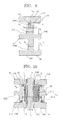
- Figure 10 is a cross section in which a central vicinity of an orbiting scroll 31 of a double-sided spiral scroll compressor shown in Embodiment 5 is enlarged.
- an inside diameter of the upper seal ring groove 31E and an inside diameter of the lower seal ring groove 31F of the orbiting scroll 31 were assumed to be equal.
- an inside diameter d 1 of an upper seal ring groove 31E of an orbiting scroll 31 is smaller than an inside diameter d 2 of a lower seal ring groove 31F.
- the rest of the configuration is similar to the scroll compressor shown in Embodiment 1, and identical numbering has been allocated to identical parts.
- Embodiment 5 of the present invention is configured such that the pressure inside the sealed vessel 1 is equal to the intake pressure of the gas. For this reason, a pressure P H on an outer portion of the bulb portion 31A is greater than a pressure P L on an inner portion.
- the thrust load F B that acts on the bulb portion 31A can be expressed by Mathematical Formula 9.
- the gap between the base plate 34A of the lower spiral tooth 31M and the lower fixed scroll 34 is further reduced. Consequently, by making the seal ring groove 31E on the surface on which the spiral tooth 31L is disposed, to which a tip seal 36 is mounted, have an inside diameter d 1 that is less than the inside diameter d 2 of the seal ring groove 31F on the surface on which the spiral tooth 31M is disposed, to which a tip seal 36 is not mounted, leakage loss can be further reduced, enabling a highly-efficient double-sided spiral scroll compressor to be obtained.
- Embodiment 5 because it is sufficient to make the shapes of all of the spiral tooth equal, and only make the inside diameter d 1 of the upper seal ring groove 31E of the orbiting scroll 31 less than the inside diameter d 2 of the lower seal ring groove 31F, one advantage is that machining is easier than for the scroll compressors shown in Embodiments 2 through 4.
- the upper seal ring groove 31E and the lower seal ring groove 31F are disposed on the bulb portion 31A of the orbiting scroll 31.
- the upper seal ring groove 31E and the lower seal ring groove 31F may also be disposed on the base plate 33A of the upper fixed scroll 33 and the base plate 34A of the lower fixed scroll 34 facing the bulb portion 31A.
Landscapes
- Engineering & Computer Science (AREA)
- Mechanical Engineering (AREA)
- General Engineering & Computer Science (AREA)
- Rotary Pumps (AREA)
Abstract
Description
- The present invention relates to a scroll compressor in which spiral teeth are formed on two surfaces of an orbiting scroll, and relates particularly to a technique that reduces leakage loss in a scroll compressor.
- One example of a scroll compressor is a configuration constituted by: an orbiting scroll having spiral teeth formed on two sides; and a pair of fixed scrolls on which spiral teeth are formed such that the respective spiral teeth intermesh (see
Patent Literature 1, for example). Hereinafter, this will be called a "double-sided spiral scroll compressor". In double-sided spiral scroll compressors of this kind, axial thrust loads due to compressed gas cancel each other out because compression chambers are formed on both sides of the orbiting scroll. - On the other hand, because there are two compression chambers in double-sided spiral scroll compressors, they have constructions in which leakage is more likely to occur from a compression side to an intake side, and it is necessary to reduce gaps between the respective spiral teeth and facing base plates in order to reduce leakage loss. However, for the orbiting scroll to move between the two fixed scrolls without being restrained, it is not possible to set the gaps between the respective spiral teeth and the base plates (hereinafter called "spiral tooth tip end gaps") too small when considering assembly precision, etc.
- For this reason, leakage from the spiral tooth tip gaps is suppressed in conventional double-sided spiral scroll compressors by disposing grooves in tip end surfaces of the spiral teeth on both sides of the orbiting scroll and in tip end surfaces of the spiral teeth in the two fixed scrolls, respectively, and mounting tip seals in the grooves to achieve reductions in leakage loss (see
Patent Literature 2, for example). - In other conventional double-sided spiral scroll compressors, tip seals are divided into two sections vertically and mating surfaces thereof are formed so as to have a saw-teeth form in order to suppress leakage from the spiral tooth tip end gaps (see
Patent Literature 3, for example). In such configurations, suppression of leakage is achieved by upper tip seals being raised onto lower tip seals by pressure differences to fill the spiral tooth tip end gaps. -
- Patent Literature 1:
Japanese Patent Laid-Open No. HEI 3-237202 - Patent Literature 2:
Japanese Patent Laid-Open No. HEI 9-324770 - Patent Literature 3:
Japanese Patent Laid-Open No. HEI 7-310682 - However, in conventional double-sided spiral scroll compressors such as those described above, leakage cannot be suppressed along the spiral teeth from spiral tooth tip end gaps on tip seal side surfaces. In particular, because pathways for this leakage exist in two positions in double-sided spiral scroll compressors, that is to say on both sides of the orbiting scroll, one important task has been to try to reduce the leakage loss from the spiral tooth tip end gaps in order to achieve increased performance in double-sided spiral scroll compressors.
- The present invention aims to solve the above problems and an object of the present invention is to provide a scroll compressor that has reduced leakage loss and high efficiency.
- In order to achieve the above object, according to one aspect of the present invention, there is provided a scroll compressor including: an orbiting scroll that has spiral teeth on two surfaces; and a pair of fixed scrolls that are installed so as to face the surfaces of the orbiting scroll and that have spiral teeth that intermesh with the spiral teeth of the orbiting scroll, characterized in that tip seals are mounted only to a spiral tooth of the fixed scroll that intermeshes with a first spiral tooth of the orbiting scroll and to the first spiral tooth of the orbiting scroll.
- According to the present invention, because an orbiting scroll that has spiral teeth on two surfaces, and a pair of fixed scrolls that are installed so as to face the surfaces of the orbiting scroll and that have spiral teeth that intermesh with the spiral teeth of the orbiting scroll are included, and tip seals are mounted only to a spiral tooth of the fixed scroll that intermeshes with a first spiral tooth of the orbiting scroll and to the first spiral tooth of the orbiting scroll, a scroll compressor that has reduced leakage loss and high efficiency can be provided.
-
- Figure 1 is a cross section showing a configuration of a scroll compressor according to
Embodiment 1 of the present invention; - Figure 2 is a diagram explaining a configuration of an orbiting scroll of the scroll compressor according to
Embodiment 1 of the present invention; - Figure 3 is a diagram explaining a configuration of a bulb portion that is positioned at a central portion of the orbiting scroll of the scroll compressor according to
Embodiment 1 of the present invention; - Figure 4 is a cross section in which a vicinity of a seal ring of the scroll compressor according to
Embodiment 1 of the present invention is enlarged; - Figure 5 is a diagram explaining a configuration of a lower fixed scroll of the scroll compressor according to
Embodiment 1 of the present invention; - Figure 6 is a cross section in which a central vicinity of the orbiting scroll of the scroll compressor according to
Embodiment 1 of the present invention is enlarged; - Figure 7 is a schematic diagram for explaining thrust loads that act on the orbiting scroll in the scroll compressor according to
Embodiment 1 of the present invention; - Figure 8 is a schematic diagram for explaining thrust loads that act on a tip seal in the scroll compressor according to
Embodiment 1 of the present invention; - Figure 9 is a cross section in which an orbiting scroll of a scroll compressor according to
Embodiment 2 of the present invention is enlarged; and - Figure 10 is a cross section in which a central vicinity of an orbiting scroll of a scroll compressor according to
Embodiment 5 of the present invention is enlarged. - Figure 1 is a cross section showing a configuration of a double-sided spiral scroll compressor according to
Embodiment 1 of the present invention. - In Figure 1, a
motor 2 is disposed in an upper portion inside a vertical sealedvessel 1, and acompression portion 3 is disposed below themotor 2. A lubricatingoil storage chamber 4 for storing lubricatingoil 41 is formed further below thecompression portion 3. Asuction pipe 5 for sucking in gas is disposed on a side surface of the sealedvessel 1 at an intermediate portion between themotor 2 and thecompression portion 3, and adischarge pipe 8 for discharging compressed gas is disposed on thecompression portion 3. In addition, aglass terminal 6 for supplying electric power is disposed on an upper end of the sealedvessel 1. Themotor 2 is constituted by: astator 21 that is formed so as to have a ring shape; and arotor 22 that is supported inside thestator 21 so as to be rotatable. Amain shaft 7 is fixed to therotor 22 and passes through thecompression portion 3, and an end portion of themain shaft 7 is immersed in the lubricatingoil 41 in the lubricatingoil storage chamber 4. - The
compression portion 3 has: anorbiting scroll 31; an upperfixed scroll 33 and a lowerfixed scroll 34 that are installed so as to face two surfaces of the orbitingscroll 31; and a commonly-known Oldhamcoupling 35 that is disposed between the lowerfixed scroll 34 and the orbitingscroll 31. An upperspiral tooth 31L and a lowerspiral tooth 31M are disposed on two surfaces of abase plate 31B of theorbiting scroll 31 so as to be symmetrical and also equal in height to each other. - A
spiral tooth 33E is disposed on a surface of abase plate 33A of the upper fixedscroll 33 that faces theorbiting scroll 31 so as to intermesh with the upperspiral tooth 31L of the orbitingscroll 31, and the upperspiral tooth 31L of the orbitingscroll 31 and thespiral tooth 33E of the upper fixedscroll 33 form anupper compression chamber 32A. Similarly, aspiral tooth 34E is disposed on a surface of abase plate 34A of the lowerfixed scroll 34 that faces theorbiting scroll 31 so as to intermesh with the lowerspiral tooth 31M of the orbitingscroll 31, and the lowerspiral tooth 31M of the orbitingscroll 31 and thespiral tooth 34E of the lowerfixed scroll 34 form alower compression chamber 32B. -
Tip seals 36 are mounted to a tip end surface of the upperspiral tooth 31L of the orbitingscroll 31 and a tip end surface of thespiral tooth 33E of the upper fixedscroll 33.Seal rings 37 are also disposed inside the upperspiral tooth 31L and the lowerspiral tooth 31M, respectively, of the orbiting scroll 31 outside themain shaft 7. - Figure 2 is a diagram explaining a configuration of an orbiting scroll according to
Embodiment 1, Figure 2(a) being a top plan of the orbiting scroll, Figure 2(b) being a bottom plan of the orbiting scroll, and Figure 2(c) being a cross section taken along line A - A in Figure 2(b). Figure 3 is a diagram explaining a configuration of a bulb portion that is positioned at a central portion of the orbiting scroll, Figure 3(a) being a perspective showing the shape of the bulb portion, and Figure 3(b) being a perspective showing a configuration of seal rings that are installed on an upper surface and a lower surface of the bulb portion. Detailed configuration of the orbitingscroll 31 will now be explained. - As shown in Figures 2 and 3(a), the
orbiting scroll 31 has: abulb portion 31A that constitutes a central portion and is constituted by curves such as arcs, etc.; and a disk-shaped base plate 31B that extends outside thebulb portion 31A. The upperspiral tooth 31L and the lowerspiral tooth 31M, which are symmetrical and are approximately equal in height to thebulb portion 31A, are formed on an upper surface and a lower surface of thebase plate 31B by involute curves or arcs. Here, "symmetrical" means configured such that thickness t, height h, pitch p, and number of turns n of the spiral teeth are all equal.
Atip seal groove 31H for mounting atip seal 36 is formed on the tip end surface of the upperspiral tooth 31L. On the other hand, atip seal groove 31H for mounting atip seal 36 is not formed on the tip end surface of the lowerspiral tooth 31M. - A main shaft aperture 31C through which the
main shaft 7 passes is formed on a central portion of thebulb portion 31A, and an orbiting shaft bearing 31D is disposed on an inner wall thereof. An upperseal ring groove 31E and a lowerseal ring groove 31F are formed on an outer portion of the orbiting shaft bearing 31D on the upper surface and the lower surface, respectively, of the bulb portion A, andseal rings 37 having anabutted joint 37A as shown in Figure 3(b) are installed in the upperseal ring groove 31E and the lowerseal ring groove 31F. In addition, a communicatingport 31K that connects theupper compression chamber 32A and thelower compression chamber 32B is disposed outside thebulb portion 31A. - Figure 4 is a cross section in which a vicinity of a seal ring is enlarged in order to explain effects of a contact sealing action of the seal rings.
- As shown in Figure 4, the
seal ring 37 is pressed from the left and from below, which are on a high-pressure side, as indicated by the arrows, due to differential pressure on two sides of the compression chamber that are partitioned off. For this reason, theseal ring 37 is pressed against a wall to the right of theseal ring groove 31E and thebase plate 33A of thefixed scroll 33 above inside theseal ring groove 31E, forming a contact seal between theorbiting scroll 31 and the upper fixedscroll 33. Contact sealing actions of theseal ring 37 are also similar on the lower surface of the orbitingscroll 31, that is, between theorbiting scroll 31 and the lowerfixed scroll 34. - A communicating
port 31K that merges gas compressed in theupper compression chamber 32A and thelower compression chamber 32B and directs it toward adischarge port 34F on the lower fixedscroll 34 is disposed on theorbiting scroll 31 as shown in Figure 2. The communicatingport 31K is formed so as to pass vertically through thebase plate 31B outside the upperseal ring groove 31E and the lowerseal ring groove 31F. The communicatingport 31K is disposed at a position where it does not span the partitioned compression chambers in theupper spiral tooth 31L or thelower spiral tooth 31M and where it always communicates with thedischarge port 34F that is disposed on the lower fixedscroll 34 even during orbital motion. - Figure 5 is a diagram explaining a configuration of a lower fixed scroll, Figure 5(a) being a top plan, and Figure 5(b) being a cross section taken along line A - A in Figure 5(a). Configuration of the lower fixed
scroll 34 will now be explained. - As shown in Figure 5, a
main shaft aperture 34B through which themain shaft 7 passes is formed on a central portion of thebase plate 34A of the lower fixedscroll 34, and a main shaft bearing 34C is disposed on an inner surface of themain shaft aperture 34B. Arecess portion 34D that accommodates thebulb portion 31A of the orbitingscroll 31 and permits orbital motion of the orbitingscroll 31 is formed on an upper surface of the lower fixedscroll 34 at an outer portion of the main shaft bearing 34C. Aspiral tooth 34E that has a thickness t, a height h, a pitch p, and number of turns n identical to those of thelower spiral tooth 31M of the orbitingscroll 31 and has a phase rotated by 180 degrees is formed outside therecess portion 34D. - A
discharge port 34F for discharging compressed gas is disposed in therecess portion 34D at a position where it does not face theseal ring 37 that is installed on theorbiting scroll 31 and where it always communicates with the communicatingport 31K of the orbitingscroll 31. Adischarge flow channel 34G that communicates with thedischarge port 34F and directs compressed gas to thedischarge pipe 8 disposed on the sealedvessel 1 is formed on the lower fixedscroll 34, and adischarge valve 34H for preventing reverse flow of gas is disposed inside thedischarge flow channel 34G at a position facing thedischarge port 34F. In addition, asuction port 34J that sucks gas into thelower compression chamber 32B is disposed on an outermost portion of the lower fixedscroll 34. - Figure 6 is a cross section in which a central vicinity of the orbiting scroll of the scroll compressor according to
Embodiment 1 is enlarged. - In Figure 6, a
main shaft aperture 33B through which themain shaft 7 passes is formed on a central portion of thebase plate 33A of the upper fixedscroll 33 in a similar manner to the lower fixedscroll 34 shown in Figure 5, and a main shaft bearing 33C is disposed on an inner surface of themain shaft aperture 33B. Aslider 38 that is fitted onto themain shaft 7 is disposed between the orbiting shaft bearing 31D and themain shaft 7 and, together with themain shaft 7, constitutes an eccentric shaft that drives the orbitingscroll 31 by means of the orbiting shaft bearing 31D.Tip seal grooves upper spiral tooth 31L of the orbitingscroll 31 and a tip end surface of thespiral tooth 33E of the upper fixedscroll 33, respectively, and tip seals 36 are mounted into each of thetip seal grooves lower spiral tooth 31M of the orbitingscroll 31 or to a tip end surface of thespiral tooth 34E of the lower fixedscroll 34. - Operation of a double-sided spiral scroll compressors according to
Embodiment 1 of the present invention will now be explained. - As shown in Figure 1, gas that is sucked inside the sealed
vessel 1 through thesuction pipe 5 flows into a portion where themotor 2 is installed, and cools themotor 2. The gas that has been sucked in is introduced through a suction port 33J that is disposed on an outer portion of the upper fixedscroll 33 into theupper compression chamber 32A and thelower compression chamber 32B that are formed on the two surfaces of the orbitingscroll 31 as indicated by arrows. - The orbiting
scroll 31 orbits relative to the upper fixedscroll 33 and the lower fixedscroll 34 without autorotating, such that the volumes of the crescent-shapedupper compression chamber 32A andlower compression chamber 32B that are formed are gradually reduced toward the center, and the gas is compressed by a commonly-known compression principle. The gas compressed in theupper compression chamber 32A and thelower compression chamber 32B, respectively, merges at thedischarge port 34F, passes through thedischarge flow channel 34G, and flows out of the sealedvessel 1 through thedischarge pipe 8. - In the above compression process, thrust loads are generated in a thrust direction (axial direction) by the gas compressed by the
upper compression chamber 32A and thelower compression chamber 32B, respectively. Magnitude of the thrust loads that act on theorbiting scroll 31 will now be explained. Figure 7 is a schematic diagram for explaining the thrust loads that act on theorbiting scroll 31. - The
tip seal 36 exhibits behavior similar to that of theseal ring 37 shown in Figure 4, and is pushed from a high-pressure side toward a low-pressure side by differential pressure between compression chambers that are partitioned off on both sides. If we assume that the right side of theupper spiral tooth 31L in Figure 7 is the high-pressure side (pressure P1), and the left side is the low-pressure side (pressure P2), then thetip seal 36 is pressed from the right and from below, and forms a contact seal inside thetip seal groove 31H by being pressed against a wall of thetip seal groove 31H on the left and thebase plate 33A above. Because of this, the pressure P1 on the high-pressure side acts on a bottom surface of thetip seal groove 31H of the orbitingscroll 31 and a spiral tooth inner tip end surface, and the pressure P2 on the low-pressure side acts on a spiral tooth outer tip end surface. - The thrust load F that acts on the
orbiting scroll 31 will now be explained. Because the pressure that acts on the upper surface and the pressure that acts on the lower surface are equal in portions of thebase plate 31B where there is noupper spiral tooth 31L and nolower spiral tooth 31M, the thrust loads cancel each other out. - However, in portions where the
upper spiral tooth 31L and thelower spiral tooth 31M are disposed, the thrust load F1 that acts on the tip end surface of theupper spiral tooth 31L and the thrust load F2 per unit length that acts on the tip end surface of thelower spiral tooth 31M differ from each other. If we let overall thickness of theupper spiral tooth 31L and thelower spiral tooth 31M be t, and width of the outer tip end surface of theupper spiral tooth 31L be t12, then thrust load per unit length F1 that acts on the tip end surface of theupper spiral tooth 31L can be expressed byMathematical Formula 1. -

- On the other hand, because a pressure that is an average of the pressure P1 on the high-pressure side and the pressure P2 on the low-pressure side acts on the tip end surface of the orbiting scroll
lower spiral tooth 31M, on which a tip seal is not disposed, thrust load per unit length F2 that acts on the tip end surface of thelower spiral tooth 31M can be expressed byMathematical Formula 2. -

- Consequently, the thrust load per unit length F that acts on the portions of the orbiting
scroll 31 where theupper spiral tooth 31L and thelower spiral tooth 31M are disposed can be expressed byMathematical Formula 3. -

- Because a width t11 of the spiral tooth inner tip end surface and the width t12 of the spiral tooth outer tip end surface of the upper spiral tooth 33L are normally equal, if we let a width of the
tip seal groove 31H be t10, then the thrust load per unit length F that acts on the portions of the orbitingscroll 31 where theupper spiral tooth 31L and thelower spiral tooth 31M are disposed is given byMathematical Formula 4. -

- Consequently, the direction of the thrust load per unit length F that acts on the portions of the orbiting
scroll 31 where theupper spiral tooth 31L and thelower spiral tooth 31M are disposed is downward, and because the thrust load acting on theorbiting scroll 31 as a whole is also directed downward, the orbitingscroll 31 is pressed downward and comes into contact with the lower fixedscroll 34. Because of this, a gap between thelower spiral tooth 31M of the orbitingscroll 31 and thebase plate 34A of the lower fixedscroll 34 is almost eliminated (a limited gap that results from surface roughness of thelower spiral tooth 31M and thebase plate 34A of the lower fixedscroll 34 remains). In contrast to that, a gap between theupper spiral tooth 31L of the orbitingscroll 31 and thebase plate 33A of the upper fixedscroll 33 is almost eliminated by the sealing action of thetip seal 36. However, there is a spiral toothtip end gap 31N at a tip end portion of theupper spiral tooth 31L near a side surface of thetip seal 36, and leakage occurs in a direction parallel to theupper spiral tooth 31L from this spiral toothtip end gap 31N. - If, on the other hand, the tip seals 36 are mounted to the
upper spiral tooth 31L and thelower spiral tooth 31M of the orbitingscroll 31, to thespiral tooth 33E of the upper fixedscroll 33, and to thespiral tooth 34E of the lower fixedscroll 34, leakage occurs on the two surfaces of the orbitingscroll 31 in directions parallel to theupper spiral tooth 31L and thelower spiral tooth 31M, respectively. Consequently, leakage in directions parallel to the spiral teeth can be reduced if the tip seals 36 are mounted only to theupper spiral tooth 31L and thespiral tooth 33E of the upper fixedscroll 33 compared to when the tip seals 36 are mounted to all of thespiral tooth - Sliding loss when a
tip seal 36 is not mounted and sliding loss when atip seal 36 is mounted will now be compared. Contact load per unit length in a spiral tooth to which atip seal 36 is not mounted is a contact load per unit length FS on thebase plate 34A of thelower spiral tooth 31M shown in Figure 7, and is given by the thrust load per unit length F that acts on theorbiting scroll 31 shown inMathematical Formula 4. - Figure 8 is a schematic diagram for explaining thrust loads that act on a tip seal. The contact load per unit length on a spiral tooth to which a tip seal is mounted is a contact load per unit length FC of the
tip seal 36 relative to thebase plate 33A. - If we let tip seal width be t3, then a thrust load per unit length F3 that pushes the
tip seal 36 upward can be expressed byMathematical Formula 5. -

- On the other hand, a thrust load per unit length F4 that pushes the
tip seal 36 downward can be expressed byMathematical Formula 6. -

- Consequently, the contact load per unit length FC of the
tip seal 36 relative to thebase plate 33A can be expressed byMathematical Formula 7. -

- When
Mathematical Formula 4 andMathematical Formula 7 are compared, the contact load per unit length FS of thelower spiral tooth 31M relative to thebase plate 34A and the contact load per unit length FC of thetip seal 36 relative to thebase plate 33A are approximately equal because the width t10 of thetip seal groove 31H and the width t3 of thetip seal 36 are approximately equal. Consequently, even if atip seal 36 is not mounted to a spiral tooth, there is hardly any increase in sliding loss due to contact compared to when atip seal 36 is mounted to the spiral tooth. - A double-sided spiral scroll compressor according to the present invention and the double-sided spiral scroll compressor that is disclosed as a conventional example in
Patent Literature 3 will now be compared. In the double-sided spiral scroll compressor that is disclosed inPatent Literature 3, tip seals are divided into two sections vertically and mating surfaces thereof are formed so as to have a saw-teeth form as a means of reducing gaps in a height direction of spiral teeth on two surfaces. InPatent Literature 3, the upper tip seal is raised on one side by gas pressure and fills the gap in the height direction. As a result, a gap in the height direction is eliminated, and a force is generated in the tip seal that presses the orbiting scroll. InPatent Literature 3, because the orbiting scroll can be pressed by this force, a tip seal is considered unnecessary in the orbiting scroll spiral tooth and the fixed scroll spiral tooth constituting one of the compression chambers. - However,
Patent Literature 3 has a complicated configuration in which the tip seals are specifically divided into two sections and mating surfaces thereof are further formed so as to have a saw-teeth form as a means of filling the gap in the height direction and pushing the orbiting scroll against one side. In contrast to that, a double-sided spiral scroll compressor according to the present invention makes use of an effect by which the tip seal rises by gas force and enables the spiral tooth height gap to be eliminated, and it has been found in the present invention for the first time that thrust gas loads that act on the two compression chambers differ from each other depending on the presence or absence of the tip seals, and in addition that this thrust gas load difference acts in such a direction as to push the orbiting scroll toward the compression chamber where there is no tip seal, enabling effects similar to those ofPatent Literature 3 to be exhibited using an extremely simple configuration. SincePatent Literature 3 does not make use of the effect by which the tip seal itself rises and enables the spiral tooth height gap to be eliminated, and nor has it found that load differences occur in the thrust gases due to the presence or absence of the tip seals, an extremely complicated configuration must be adopted so as to eliminate the spiral tooth tip end gap and push the orbiting scroll against one side. Dividing the tip seals into two sections and forming mating surfaces thereof so as to have a saw-teeth form increases parts costs, and also makes processes complicated during manufacturing. In addition, by forming the tip seals so as to have a saw-teeth form, cracking is more likely to occur and there is a risk that the tip seals may rupture. - Moreover, in
Embodiment 1, tip seals 36 are mounted only to theupper spiral tooth 31L of the orbitingscroll 31 and thespiral tooth 33E of the upper fixedscroll 33, and tip seals are not mounted to thelower spiral tooth 31M of the orbitingscroll 31 or thespiral tooth 34E of the lower fixedscroll 34. However, if tip seals 36 are mounted only to thelower spiral tooth 31M of the orbitingscroll 31 and thespiral tooth 34E of the lower fixedscroll 34 and tip seals 36 are not mounted to theupper spiral tooth 31L of the orbitingscroll 31 or thespiral tooth 33E of the upper fixedscroll 33, leakage in a direction parallel to the spiral teeth can also be similarly reduced compared to when the tip seals 36 are mounted to all of thespiral tooth - From the above, it can be seen that by adopting a configuration in which tip seals are mounted only to a first spiral tooth of the orbiting
scroll 31 and the spiral tooth of the fixed scroll intermeshing with that spiral tooth and tip seals are not mounted to a second spiral tooth of the orbitingscroll 31 or the spiral tooth of the fixed scroll intermeshing with that spiral tooth, leakage loss can be reduced more in double-sided spiral scroll compressors than when tip seals 36 are mounted to all of the spiral teeth. - Sliding loss when tip seals 36 are mounted only to a first spiral tooth of the orbiting
scroll 31 and the spiral tooth of the fixed scroll intermeshing with that spiral tooth and tip seals 36 are not mounted to a second spiral tooth of the orbitingscroll 31 or the spiral tooth of the fixed scroll intermeshing with that spiral tooth hardly increases at all compared to sliding loss when tip seals 36 are mounted to all of the spiral teeth. Because of this, by adopting a configuration in which tip seals 36 are mounted only to a first spiral tooth of the orbitingscroll 31 and the spiral tooth of the fixed scroll intermeshing with that spiral tooth and tip seals 36 are not mounted to a second spiral tooth of the orbitingscroll 31 or the spiral tooth of the fixed scroll intermeshing with that spiral tooth, a double-sided spiral scroll compressor can be obtained that has less leakage loss and higher efficiency than double-sided spiral scroll compressors in which tip seals are mounted to all of the spiral teeth. - In addition, by adopting this kind of construction, material costs and machining costs can be reduced because the quantity of tip seals 36 can be reduced from four to two, and machining positions for the tip seal grooves can also be reduced from four positions to two positions. In addition, because positions for mounting the tip seals 36 can be reduced from four positions to two positions, another advantage arising is that assembly is facilitated.
- In
Embodiment 1, the width t11 of the spiral tooth inner tip end surface was assumed to be equal to the width t12 of the spiral tooth outer tip end surface in theupper spiral tooth 31L of the orbitingscroll 31. However, even if the width t11 of the spiral tooth inner tip end surface and the width t12 of the spiral tooth outer tip end surface of theupper spiral tooth 31L of the orbitingscroll 31 are not equal, it can be seen that fromMathematical Formula 3 that the thrust load F will be directed downward if t - 2t12 > 0. - Consequently, by mounting the tip seals 36 only to a first spiral tooth of the orbiting
scroll 31 and the spiral tooth of the fixed scroll intermeshing with that spiral tooth, and reducing the width of the outer tip end surface to less than half the spiral tooth thickness t in the spiral tooth mounted with atip seal 36, a double-sided spiral scroll compressor can be obtained that has less leakage loss and higher efficiency than double-sided spiral scroll compressors in which tip seals are mounted to all of the spiral teeth. - In
Embodiment 1, the heights h of theupper spiral tooth 31L and thelower spiral tooth 31M of the orbitingscroll 31, thespiral tooth 33E of the upper fixedscroll 33, and thespiral tooth 34E of the lower fixedscroll 34 are all assumed to be equal. However, the heights of theupper spiral tooth 31L and thelower spiral tooth 31M may also differ from each other provided that the heights of theupper spiral tooth 31L and thespiral tooth 33E of the upper fixedscroll 33 are equal and the heights of thelower spiral tooth 31M and thespiral tooth 34E of the lower fixedscroll 34 are equal, . - In addition, because working pressure is high and the influence of leakage from the spiral tooth tip end gaps is increased if carbon dioxide is used for the gas that is compressed in
Embodiment 1, leakage loss can be reduced greatly and effects improving efficiency can be further increased by mounting tip seals only to a first spiral tooth of the orbitingscroll 31 and the spiral tooth of the fixed scroll intermeshing with that spiral tooth in the double-sided spiral scroll compressor. -
Embodiment 1 of the present invention is configured such that the pressure inside the sealedvessel 1 that accommodates the orbitingscroll 31, the upper fixedscroll 33, and the lower fixedscroll 34 is equal to an intake pressure of the gas. However, the present invention may also be configured such that the pressure inside the sealedvessel 1 is equal to a discharge pressure of the gas. If configured such that the pressure inside the sealedvessel 1 is equal to the discharge pressure of the gas, it is necessary to dispose the seal rings 37 outside theupper spiral tooth 31L and thelower spiral tooth 31M of the orbitingscroll 31. - Figure 9 is a cross section in which an orbiting scroll of a scroll compressor shown in
Embodiment 2 is enlarged. InEmbodiment 1, shapes of theupper spiral tooth 31L and thelower spiral tooth 31M of the orbitingscroll 31 are configured symmetrically. InEmbodiment 2, number of turns n and orbiting radius r of anupper spiral tooth 31L and alower spiral tooth 31M are made identical, and a thickness t1 of theupper spiral tooth 31L, to which atip seal 36 is mounted, is made greater than a thickness t2 of thelower spiral tooth 31M. Here, the orbiting radius r can be expressed byMathematical Formula 8 using thickness t and pitch p of the spiral teeth. -

- Consequently, because the orbiting radii r of the
upper spiral tooth 31L and thelower spiral tooth 31M are equal, and the thickness t1 of theupper spiral tooth 31L is greater than the thickness t2 of thelower spiral tooth 31M, the pitch p1 of theupper spiral tooth 31L is greater than the pitch p2 of thelower spiral tooth 31M. Thickness t, height h, pitch p, and number of turns n in aspiral tooth 33E of an upper fixedscroll 33 are all equal to those of theupper spiral tooth 31L of the orbitingscroll 31, and the phase thereof is rotated by 180 degrees. Similarly, thickness t, height h, pitch p, and number of turns n in aspiral tooth 34E of a lower fixedscroll 34 are all equal to those of thelower spiral tooth 31M of the orbitingscroll 31, and the phase thereof is rotated by 180 degrees. The rest of the configuration is similar to the scroll compressor shown inEmbodiment 1, and identical numbering has been allocated to parts identical to those ofEmbodiment 1. - Because the thickness t1 and the pitch p1 of the
upper spiral tooth 31L of the orbitingscroll 31, to which atip seal 36 is mounted, are greater than the thickness t2 and the pitch p2 of thelower spiral tooth 31M, to which atip seal 36 is not mounted, cross-sectional area of the compression chambers in a direction perpendicular to themain shaft 7 is greater in theupper compression chamber 32A that is constituted by the orbitingscroll 31 and the upper fixedscroll 33 than in thelower compression chamber 32B that is constituted by the orbitingscroll 31 and the lower fixedscroll 34. Thus, because the thrust load F1 is increased and the thrust load F that acts on the orbiting scrolls is increased, the gap between thelower spiral tooth 31M and thebase plate 34A of the lower fixedscroll 34 is further reduced, enabling leakage loss to be further reduced, and enabling a highly-efficient scroll compressor to be obtained. - By disposing a means of applying a thrust load to the
orbiting scroll 31 in the above manner from a fixed scroll to which atip seal 36 is mounted toward a fixed scroll to which atip seal 36 is not mounted, leakage loss can be further reduced, enabling a highly-efficient scroll compressor to be obtained. - In
Embodiment 2, a height h1 of theupper spiral tooth 31L and a height h2 of thelower spiral tooth 31M are assumed to be equal, but the height h1 of theupper spiral tooth 31L and the height h2 of thelower spiral tooth 31M may also be made to differ from each other such that radial load becomes equal. - In
Embodiment 1, shapes of theupper spiral tooth 31L and thelower spiral tooth 31M of the orbitingscroll 31 are configured symmetrically. InEmbodiment 3, a thickness t, pitch p, and orbiting radius r of anupper spiral tooth 31L and alower spiral tooth 31M are made identical, and the number of turns n1 in theupper spiral tooth 31L, to which atip seal 36 is mounted, is made greater than the number of turns n2 in thelower spiral tooth 31M, to which a tip seal is not mounted. - Thickness t, height h, pitch p, and number of turns n in a
spiral tooth 33E of an upper fixedscroll 33 are all equal to those of theupper spiral tooth 31L of the orbitingscroll 31, and the phase thereof is rotated by 180 degrees. Similarly, thickness t, height h, pitch p, and number of turns n in aspiral tooth 34E of a lower fixedscroll 34 are all equal to those of theupper spiral tooth 31L of the orbitingscroll 31, and the phase thereof is rotated by 180 degrees. The rest of the configuration is similar to the scroll compressor shown inEmbodiment 1, and identical numbering has been allocated to parts identical to those ofEmbodiment 1. - By making the number of turns n1 in the
upper spiral tooth 31L of the orbitingscroll 31, to which atip seal 36 is mounted, greater than the number of turns n2 in thelower spiral tooth 31M, to which atip seal 36 is not mounted, cross-sectional area of the compression chambers in a direction perpendicular to themain shaft 7 becomes greater in theupper compression chamber 32A that is constituted by the orbitingscroll 31 and the upper fixedscroll 33 than in thelower compression chamber 32B that is constituted by the orbitingscroll 31 and the lower fixedscroll 34. Thus, because the thrust load F1 is increased and the thrust load F that acts on the orbiting scrolls is increased, the gap between thelower spiral tooth 31M and thebase plate 34A of the lower fixedscroll 34 is further reduced, enabling leakage loss to be further reduced, and enabling a highly-efficient double-sided spiral scroll compressor to be obtained. - By disposing a means of applying a thrust load to the
orbiting scroll 31 in the above manner from a fixed scroll to which atip seal 36 is mounted toward a fixed scroll to which atip seal 36 is not mounted, leakage loss can be further reduced, enabling a highly-efficient scroll compressor to be obtained. - In
Embodiment 3, a height h1 of theupper spiral tooth 31L and a height h2 of thelower spiral tooth 31M are assumed to be equal, but the height h1 of theupper spiral tooth 31L and the height h2 of thelower spiral tooth 31M may also be made to differ from each other such that radial load becomes equal. - In
Embodiment 2, the orbiting radius r and the number of turns n in theupper spiral tooth 31L and thelower spiral tooth 31M of the orbitingscroll 31 were equal, and the thickness t and the pitch p were greater in theupper spiral tooth 31L than in thelower spiral tooth 31M. InEmbodiment 3, the orbiting radius r, thickness t, and pitch p in theupper spiral tooth 31L and thelower spiral tooth 31M of the orbitingscroll 31 were equal, and the number of turns n were greater in theupper spiral tooth 31L than in thelower spiral tooth 31M. - In
Embodiment 4, an orbiting radius r of anupper spiral tooth 31L and alower spiral tooth 31M of anorbiting scroll 31 are equal, thickness t and pitch p are greater in theupper spiral tooth 31L than in thelower spiral tooth 31M, and the number of turns n is greater in theupper spiral tooth 31L than in thelower spiral tooth 31M. - By making the thickness t and the pitch p greater in the
upper spiral tooth 31L of the orbitingscroll 31, to which atip seal 36 is mounted, than in thelower spiral tooth 31M, to which atip seal 36 is not mounted, and making the number of turns n greater in theupper spiral tooth 31L than in thelower spiral tooth 31M, cross-sectional area of the compression chambers in a direction perpendicular to themain shaft 7 becomes greater in theupper compression chamber 32A that is constituted by the orbitingscroll 31 and the upper fixedscroll 33 than in thelower compression chamber 32B that is constituted by the orbitingscroll 31 and the lower fixedscroll 34. For this reason, thrust load F1 is increased and thrust load F that acts on the orbiting scrolls is increased. Thus, the gap between thelower spiral tooth 31M and thebase plate 34A of the lower fixedscroll 34 is further reduced, enabling leakage loss to be further reduced, and enabling a highly-efficient double-sided spiral scroll compressor to be obtained. - By disposing a means of applying a thrust load to the
orbiting scroll 31 in the above manner from a fixed scroll to which atip seal 36 is mounted toward a fixed scroll to which atip seal 36 is not mounted, leakage loss can be further reduced, enabling a highly-efficient scroll compressor to be obtained. - Figure 10 is a cross section in which a central vicinity of an
orbiting scroll 31 of a double-sided spiral scroll compressor shown inEmbodiment 5 is enlarged. InEmbodiment 1, an inside diameter of the upperseal ring groove 31E and an inside diameter of the lowerseal ring groove 31F of the orbitingscroll 31 were assumed to be equal. InEmbodiment 5, an inside diameter d1 of an upperseal ring groove 31E of anorbiting scroll 31 is smaller than an inside diameter d2 of a lowerseal ring groove 31F. The rest of the configuration is similar to the scroll compressor shown inEmbodiment 1, and identical numbering has been allocated to identical parts. - A thrust load FB that acts on the
bulb portion 31A of the orbitingscroll 31 will now be explained.Embodiment 5 of the present invention is configured such that the pressure inside the sealedvessel 1 is equal to the intake pressure of the gas. For this reason, a pressure PH on an outer portion of thebulb portion 31A is greater than a pressure PL on an inner portion. Here, the thrust load FB that acts on thebulb portion 31A can be expressed by Mathematical Formula 9. -

- As indicated by Mathematical Formula 9, if the inside diameter d1 of the upper
seal ring groove 31E and the inside diameter d2 of the lowerseal ring groove 31F of the orbitingscroll 31 are equal, the thrust load FB that acts on thebulb portion 31A is canceled out completely. However, when the inside diameter d1 of the upperseal ring groove 31E of the orbitingscroll 31 is smaller than the inside diameter d2 of the lowerseal ring groove 31F, as in a scroll compressor according toEmbodiment 5, the thrust load FB that acts on thebulb portion 31A is directed downward, increasing the thrust load F that acts on the orbiting scroll. - Because of this, the gap between the
base plate 34A of thelower spiral tooth 31M and the lower fixedscroll 34 is further reduced. Consequently, by making theseal ring groove 31E on the surface on which thespiral tooth 31L is disposed, to which atip seal 36 is mounted, have an inside diameter d1 that is less than the inside diameter d2 of theseal ring groove 31F on the surface on which thespiral tooth 31M is disposed, to which atip seal 36 is not mounted, leakage loss can be further reduced, enabling a highly-efficient double-sided spiral scroll compressor to be obtained. - By disposing a means of applying a thrust load to the
orbiting scroll 31 in the above manner from a fixed scroll to which atip seal 36 is mounted toward a fixed scroll to which atip seal 36 is not mounted, leakage loss can be further reduced, enabling a highly-efficient scroll compressor to be obtained. - In
Embodiment 5, because it is sufficient to make the shapes of all of the spiral tooth equal, and only make the inside diameter d1 of the upperseal ring groove 31E of the orbitingscroll 31 less than the inside diameter d2 of the lowerseal ring groove 31F, one advantage is that machining is easier than for the scroll compressors shown inEmbodiments 2 through 4. - In
Embodiment 5, the upperseal ring groove 31E and the lowerseal ring groove 31F are disposed on thebulb portion 31A of the orbitingscroll 31. However, the upperseal ring groove 31E and the lowerseal ring groove 31F may also be disposed on thebase plate 33A of the upper fixedscroll 33 and thebase plate 34A of the lower fixedscroll 34 facing thebulb portion 31A.
Claims (7)
- A scroll compressor comprising:an orbiting scroll that has spiral teeth on two surfaces; anda pair of fixed scrolls that are installed so as to face said surfaces of said orbiting scroll and that have spiral teeth that intermesh with said spiral teeth of said orbiting scroll,characterized in that:tip seals are mounted only to a spiral tooth of said fixed scroll that intermeshes with a first spiral tooth of said orbiting scroll and to said first spiral tooth of said orbiting scroll.
- A scroll compressor according to Claim 1, further comprising a thrust load applying means that applies a thrust load to said orbiting scroll in a direction from said fixed scroll to which said tip seal is mounted toward said fixed scroll to which said tip seal is not mounted.
- A scroll compressor according to Claim 2, wherein said thrust load applying means is configured such that a compressor constituted by said orbiting scroll and said fixed scroll to which said tip seal is mounted has a cross-sectional area in a direction perpendicular to a main shaft that is greater than that of a compressor constituted by said orbiting scroll and said fixed scroll to which said tip seal is not mounted.
- A scroll compressor according to Claim 3, wherein said spiral tooth of said orbiting scroll to which said tip seal is mounted has a thickness that is greater than that of said spiral tooth of said orbiting scroll to which said tip seal is not mounted.
- A scroll compressor according to Claim 3, wherein said spiral tooth of said orbiting scroll to which said tip seal is mounted has a greater number of turns than that of said spiral tooth of said orbiting scroll to which said tip seal is not mounted.
- A scroll compressor according to Claim 1, wherein:pressure inside a sealed vessel accommodating said orbiting scroll and said fixed scrolls is equal to an intake pressure;seal ring grooves for installing seal rings that seal said orbiting scroll and said fixed scrolls are formed on said orbiting scroll or said fixed scrolls; anda seal ring groove that is formed on a surface on which said spiral tooth to which said tip seal is mounted is disposed has an inside diameter that is less than that of a seal ring groove that is formed on a surface on which said spiral tooth to which said tip seal is not mounted is disposed.
- A scroll compressor according to Claim 1, wherein carbon dioxide is compressed.
Applications Claiming Priority (2)
| Application Number | Priority Date | Filing Date | Title |
|---|---|---|---|
| JP2005091113 | 2005-03-28 | ||
| PCT/JP2006/301449 WO2006103824A1 (en) | 2005-03-28 | 2006-01-30 | Scroll compressor |
Publications (3)
| Publication Number | Publication Date |
|---|---|
| EP1870598A1 true EP1870598A1 (en) | 2007-12-26 |
| EP1870598A4 EP1870598A4 (en) | 2011-08-10 |
| EP1870598B1 EP1870598B1 (en) | 2019-06-26 |
Family
ID=37053093
Family Applications (1)
| Application Number | Title | Priority Date | Filing Date |
|---|---|---|---|
| EP06712592.2A Ceased EP1870598B1 (en) | 2005-03-28 | 2006-01-30 | Scroll compressor |
Country Status (5)
| Country | Link |
|---|---|
| US (1) | US7645130B2 (en) |
| EP (1) | EP1870598B1 (en) |
| JP (1) | JP4732446B2 (en) |
| CN (1) | CN100532842C (en) |
| WO (1) | WO2006103824A1 (en) |
Cited By (1)
| Publication number | Priority date | Publication date | Assignee | Title |
|---|---|---|---|---|
| GB2503723A (en) * | 2012-07-06 | 2014-01-08 | Edwards Ltd | Scroll pump with axial seal |
Families Citing this family (4)
| Publication number | Priority date | Publication date | Assignee | Title |
|---|---|---|---|---|
| KR101088083B1 (en) * | 2009-08-11 | 2011-11-30 | 송세경 | Promotable intelligent display device and its promotion method |
| GB201007028D0 (en) * | 2010-04-28 | 2010-06-09 | Edwards Ltd | Scroll pump |
| JP5800917B2 (en) * | 2012-02-02 | 2015-10-28 | 三菱電機株式会社 | Air conditioner and air conditioner for railway vehicles |
| US8961160B2 (en) | 2013-03-29 | 2015-02-24 | Agilent Technologies, Inc. | Scroll pump having separable orbiting plate scroll and method of replacing tip seal |
Family Cites Families (19)
| Publication number | Priority date | Publication date | Assignee | Title |
|---|---|---|---|---|
| JPS57203801A (en) * | 1981-06-09 | 1982-12-14 | Nippon Denso Co Ltd | Scroll type hydraulic machine |
| JPS6053601A (en) * | 1983-09-01 | 1985-03-27 | Mitsubishi Electric Corp | Scroll type hydraulic machine |
| JPS6158991A (en) * | 1984-08-29 | 1986-03-26 | Toshiba Corp | Scrol type compressor |
| JPH03104194A (en) * | 1989-09-18 | 1991-05-01 | Fujitsu Ltd | Electronic circuit equipment |
| US5035589A (en) * | 1990-01-16 | 1991-07-30 | Carrier Corporation | Method and apparatus for reducing scroll compressor tip leakage |
| JPH03104194U (en) * | 1990-02-09 | 1991-10-29 | ||
| JPH03237282A (en) * | 1990-02-09 | 1991-10-23 | Mitsubishi Heavy Ind Ltd | Scroll compressor |
| JPH06102961B2 (en) | 1990-02-13 | 1994-12-14 | 岩田塗装機工業株式会社 | Scroll type fluid machinery |
| JPH07310682A (en) * | 1994-05-17 | 1995-11-28 | Hitachi Ltd | Scroll type fluid machine |
| US5616015A (en) * | 1995-06-07 | 1997-04-01 | Varian Associates, Inc. | High displacement rate, scroll-type, fluid handling apparatus |
| JPH09158853A (en) * | 1995-12-05 | 1997-06-17 | Hitachi Ltd | Scroll type fluid machine |
| JPH09324770A (en) | 1996-06-04 | 1997-12-16 | Asuka Japan:Kk | Twin type scroll fluid machine |
| JP3985051B2 (en) * | 1997-07-28 | 2007-10-03 | 独立行政法人 日本原子力研究開発機構 | Double wrap dry scroll vacuum pump |
| JP2000097174A (en) * | 1998-09-22 | 2000-04-04 | Hitachi Ltd | Peripheral drive scroll compressor |
| US6695599B2 (en) * | 2001-06-29 | 2004-02-24 | Nippon Soken, Inc. | Scroll compressor |
| US6658866B2 (en) * | 2002-02-13 | 2003-12-09 | Carrier Corporation | Scroll expressor |
| JP3876756B2 (en) * | 2002-04-25 | 2007-02-07 | 株式会社日立製作所 | CO2 refrigerant compressor bearing, compressor using the same, and use thereof |
| JP4107903B2 (en) | 2002-07-29 | 2008-06-25 | 株式会社デンソー | Scroll compressor |
| JP3104194U (en) | 2003-12-10 | 2004-09-16 | 富美 渡邉 | Waterproof puff for makeup |
-
2006
- 2006-01-30 EP EP06712592.2A patent/EP1870598B1/en not_active Ceased
- 2006-01-30 JP JP2007510327A patent/JP4732446B2/en not_active Expired - Fee Related
- 2006-01-30 WO PCT/JP2006/301449 patent/WO2006103824A1/en not_active Ceased
- 2006-01-30 US US11/816,944 patent/US7645130B2/en not_active Expired - Fee Related
- 2006-01-30 CN CNB2006800099773A patent/CN100532842C/en not_active Expired - Fee Related
Cited By (3)
| Publication number | Priority date | Publication date | Assignee | Title |
|---|---|---|---|---|
| GB2503723A (en) * | 2012-07-06 | 2014-01-08 | Edwards Ltd | Scroll pump with axial seal |
| GB2503723B (en) * | 2012-07-06 | 2015-07-22 | Edwards Ltd | Scroll pump with axial seal |
| US10161399B2 (en) | 2012-07-06 | 2018-12-25 | Edwards Limited | Scroll pump |
Also Published As
| Publication number | Publication date |
|---|---|
| US20080193313A1 (en) | 2008-08-14 |
| JPWO2006103824A1 (en) | 2008-09-04 |
| CN101163884A (en) | 2008-04-16 |
| US7645130B2 (en) | 2010-01-12 |
| CN100532842C (en) | 2009-08-26 |
| EP1870598B1 (en) | 2019-06-26 |
| EP1870598A4 (en) | 2011-08-10 |
| JP4732446B2 (en) | 2011-07-27 |
| WO2006103824A1 (en) | 2006-10-05 |
Similar Documents
| Publication | Publication Date | Title |
|---|---|---|
| CN105164419B (en) | scroll compressor | |
| US7497674B2 (en) | Scroll compressor having shoulder and rotation-preventing portions positioned as different phases | |
| CN109312740B (en) | Scroll fluid machine and tip seal | |
| EP2894338A1 (en) | Scroll compressor | |
| CN109306959B (en) | Back pressure cavity pressure stabilizing structure and vortex compressor with same | |
| EP1870598B1 (en) | Scroll compressor | |
| WO2004111462A1 (en) | Scroll compressor | |
| EP3754198A1 (en) | Scroll fluid machine | |
| JP2009243346A (en) | Scroll compressor | |
| JP5622473B2 (en) | Scroll compressor | |
| US6527527B2 (en) | Scroll compressor | |
| KR102326912B1 (en) | Scroll fluid machine and scroll member used therein | |
| JP2006348902A (en) | Scroll compressor | |
| JP2005163745A (en) | Scroll compressor | |
| JP4410726B2 (en) | Scroll compressor | |
| CN111712643B (en) | Method for machining scroll member | |
| US8282370B2 (en) | Stepped scroll compressor with changing step mesh gaps | |
| JP4466316B2 (en) | Hermetic scroll compressor | |
| JP2011032910A (en) | Scroll compressor | |
| JP2009281209A (en) | Scroll compressor | |
| EP2441959A1 (en) | Scroll compressor | |
| JP2009008006A (en) | Scroll compressor | |
| JPH07119657A (en) | Scroll type fluid machinery | |
| JP2008002287A (en) | Scroll compressor | |
| JP2000130367A (en) | Scroll compressor |
Legal Events
| Date | Code | Title | Description |
|---|---|---|---|
| PUAI | Public reference made under article 153(3) epc to a published international application that has entered the european phase |
Free format text: ORIGINAL CODE: 0009012 |
|
| 17P | Request for examination filed |
Effective date: 20071024 |
|
| AK | Designated contracting states |
Kind code of ref document: A1 Designated state(s): DE ES FR GB IT |
|
| DAX | Request for extension of the european patent (deleted) | ||
| RBV | Designated contracting states (corrected) |
Designated state(s): DE ES FR GB IT |
|
| A4 | Supplementary search report drawn up and despatched |
Effective date: 20110708 |
|
| RIC1 | Information provided on ipc code assigned before grant |
Ipc: F04C 27/00 20060101ALI20110704BHEP Ipc: F04C 18/02 20060101AFI20110704BHEP |
|
| 17Q | First examination report despatched |
Effective date: 20170424 |
|
| REG | Reference to a national code |
Ref country code: DE Ref legal event code: R079 Ref document number: 602006058204 Country of ref document: DE Free format text: PREVIOUS MAIN CLASS: F04C0018020000 Ipc: F04C0023000000 |
|
| GRAP | Despatch of communication of intention to grant a patent |
Free format text: ORIGINAL CODE: EPIDOSNIGR1 |
|
| RIC1 | Information provided on ipc code assigned before grant |
Ipc: F04C 27/00 20060101ALI20181130BHEP Ipc: F04C 23/00 20060101AFI20181130BHEP Ipc: F04C 18/02 20060101ALI20181130BHEP |
|
| INTG | Intention to grant announced |
Effective date: 20190107 |
|
| RIN1 | Information on inventor provided before grant (corrected) |
Inventor name: SUGAWA, MASAAKI Inventor name: KODA, TOSHIHIDE Inventor name: ISHIZONO, FUMIHIKO Inventor name: KAKUDA, MASAYUKI Inventor name: NAKAMURA, TOSHIYUKI Inventor name: SEKIYA, SHIN Inventor name: TOJO, KUNIO Inventor name: SUGIHARA, MASAHIRO Inventor name: YANO, KENJI |
|
| GRAS | Grant fee paid |
Free format text: ORIGINAL CODE: EPIDOSNIGR3 |
|
| GRAA | (expected) grant |
Free format text: ORIGINAL CODE: 0009210 |
|
| AK | Designated contracting states |
Kind code of ref document: B1 Designated state(s): DE ES FR GB IT |
|
| REG | Reference to a national code |
Ref country code: GB Ref legal event code: FG4D |
|
| REG | Reference to a national code |
Ref country code: DE Ref legal event code: R096 Ref document number: 602006058204 Country of ref document: DE |
|
| PG25 | Lapsed in a contracting state [announced via postgrant information from national office to epo] |
Ref country code: ES Free format text: LAPSE BECAUSE OF FAILURE TO SUBMIT A TRANSLATION OF THE DESCRIPTION OR TO PAY THE FEE WITHIN THE PRESCRIBED TIME-LIMIT Effective date: 20190626 |
|
| REG | Reference to a national code |
Ref country code: DE Ref legal event code: R097 Ref document number: 602006058204 Country of ref document: DE |
|
| PLBE | No opposition filed within time limit |
Free format text: ORIGINAL CODE: 0009261 |
|
| STAA | Information on the status of an ep patent application or granted ep patent |
Free format text: STATUS: NO OPPOSITION FILED WITHIN TIME LIMIT |
|
| 26N | No opposition filed |
Effective date: 20200603 |
|
| PGFP | Annual fee paid to national office [announced via postgrant information from national office to epo] |
Ref country code: GB Payment date: 20211209 Year of fee payment: 17 Ref country code: FR Payment date: 20211217 Year of fee payment: 17 |
|
| PGFP | Annual fee paid to national office [announced via postgrant information from national office to epo] |
Ref country code: DE Payment date: 20211207 Year of fee payment: 17 |
|
| PGFP | Annual fee paid to national office [announced via postgrant information from national office to epo] |
Ref country code: IT Payment date: 20211213 Year of fee payment: 17 |
|
| REG | Reference to a national code |
Ref country code: DE Ref legal event code: R119 Ref document number: 602006058204 Country of ref document: DE |
|
| GBPC | Gb: european patent ceased through non-payment of renewal fee |
Effective date: 20230130 |
|
| PG25 | Lapsed in a contracting state [announced via postgrant information from national office to epo] |
Ref country code: GB Free format text: LAPSE BECAUSE OF NON-PAYMENT OF DUE FEES Effective date: 20230130 Ref country code: DE Free format text: LAPSE BECAUSE OF NON-PAYMENT OF DUE FEES Effective date: 20230801 |
|
| PG25 | Lapsed in a contracting state [announced via postgrant information from national office to epo] |
Ref country code: FR Free format text: LAPSE BECAUSE OF NON-PAYMENT OF DUE FEES Effective date: 20230131 |
|
| PG25 | Lapsed in a contracting state [announced via postgrant information from national office to epo] |
Ref country code: IT Free format text: LAPSE BECAUSE OF NON-PAYMENT OF DUE FEES Effective date: 20230130 |