EP1870594A1 - Fuel injection valve - Google Patents
Fuel injection valve Download PDFInfo
- Publication number
- EP1870594A1 EP1870594A1 EP07110200A EP07110200A EP1870594A1 EP 1870594 A1 EP1870594 A1 EP 1870594A1 EP 07110200 A EP07110200 A EP 07110200A EP 07110200 A EP07110200 A EP 07110200A EP 1870594 A1 EP1870594 A1 EP 1870594A1
- Authority
- EP
- European Patent Office
- Prior art keywords
- pressure
- valve
- fuel
- valve element
- seat portion
- Prior art date
- Legal status (The legal status is an assumption and is not a legal conclusion. Google has not performed a legal analysis and makes no representation as to the accuracy of the status listed.)
- Withdrawn
Links
Images


Classifications
-
- F—MECHANICAL ENGINEERING; LIGHTING; HEATING; WEAPONS; BLASTING
- F02—COMBUSTION ENGINES; HOT-GAS OR COMBUSTION-PRODUCT ENGINE PLANTS
- F02M—SUPPLYING COMBUSTION ENGINES IN GENERAL WITH COMBUSTIBLE MIXTURES OR CONSTITUENTS THEREOF
- F02M47/00—Fuel-injection apparatus operated cyclically with fuel-injection valves actuated by fluid pressure
- F02M47/02—Fuel-injection apparatus operated cyclically with fuel-injection valves actuated by fluid pressure of accumulator-injector type, i.e. having fuel pressure of accumulator tending to open, and fuel pressure in other chamber tending to close, injection valves and having means for periodically releasing that closing pressure
- F02M47/027—Electrically actuated valves draining the chamber to release the closing pressure
-
- F—MECHANICAL ENGINEERING; LIGHTING; HEATING; WEAPONS; BLASTING
- F02—COMBUSTION ENGINES; HOT-GAS OR COMBUSTION-PRODUCT ENGINE PLANTS
- F02M—SUPPLYING COMBUSTION ENGINES IN GENERAL WITH COMBUSTIBLE MIXTURES OR CONSTITUENTS THEREOF
- F02M63/00—Other fuel-injection apparatus having pertinent characteristics not provided for in groups F02M39/00 - F02M57/00 or F02M67/00; Details, component parts, or accessories of fuel-injection apparatus, not provided for in, or of interest apart from, the apparatus of groups F02M39/00 - F02M61/00 or F02M67/00; Combination of fuel pump with other devices, e.g. lubricating oil pump
- F02M63/0012—Valves
- F02M63/0014—Valves characterised by the valve actuating means
- F02M63/0015—Valves characterised by the valve actuating means electrical, e.g. using solenoid
- F02M63/0026—Valves characterised by the valve actuating means electrical, e.g. using solenoid using piezoelectric or magnetostrictive actuators
-
- F—MECHANICAL ENGINEERING; LIGHTING; HEATING; WEAPONS; BLASTING
- F02—COMBUSTION ENGINES; HOT-GAS OR COMBUSTION-PRODUCT ENGINE PLANTS
- F02M—SUPPLYING COMBUSTION ENGINES IN GENERAL WITH COMBUSTIBLE MIXTURES OR CONSTITUENTS THEREOF
- F02M63/00—Other fuel-injection apparatus having pertinent characteristics not provided for in groups F02M39/00 - F02M57/00 or F02M67/00; Details, component parts, or accessories of fuel-injection apparatus, not provided for in, or of interest apart from, the apparatus of groups F02M39/00 - F02M61/00 or F02M67/00; Combination of fuel pump with other devices, e.g. lubricating oil pump
- F02M63/0012—Valves
- F02M63/0031—Valves characterized by the type of valves, e.g. special valve member details, valve seat details, valve housing details
-
- F—MECHANICAL ENGINEERING; LIGHTING; HEATING; WEAPONS; BLASTING
- F02—COMBUSTION ENGINES; HOT-GAS OR COMBUSTION-PRODUCT ENGINE PLANTS
- F02M—SUPPLYING COMBUSTION ENGINES IN GENERAL WITH COMBUSTIBLE MIXTURES OR CONSTITUENTS THEREOF
- F02M2200/00—Details of fuel-injection apparatus, not otherwise provided for
- F02M2200/28—Details of throttles in fuel-injection apparatus
-
- F—MECHANICAL ENGINEERING; LIGHTING; HEATING; WEAPONS; BLASTING
- F02—COMBUSTION ENGINES; HOT-GAS OR COMBUSTION-PRODUCT ENGINE PLANTS
- F02M—SUPPLYING COMBUSTION ENGINES IN GENERAL WITH COMBUSTIBLE MIXTURES OR CONSTITUENTS THEREOF
- F02M2200/00—Details of fuel-injection apparatus, not otherwise provided for
- F02M2200/70—Linkage between actuator and actuated element, e.g. between piezoelectric actuator and needle valve or pump plunger
- F02M2200/703—Linkage between actuator and actuated element, e.g. between piezoelectric actuator and needle valve or pump plunger hydraulic
-
- F—MECHANICAL ENGINEERING; LIGHTING; HEATING; WEAPONS; BLASTING
- F02—COMBUSTION ENGINES; HOT-GAS OR COMBUSTION-PRODUCT ENGINE PLANTS
- F02M—SUPPLYING COMBUSTION ENGINES IN GENERAL WITH COMBUSTIBLE MIXTURES OR CONSTITUENTS THEREOF
- F02M2547/00—Special features for fuel-injection valves actuated by fluid pressure
- F02M2547/001—Control chambers formed by movable sleeves
-
- F—MECHANICAL ENGINEERING; LIGHTING; HEATING; WEAPONS; BLASTING
- F02—COMBUSTION ENGINES; HOT-GAS OR COMBUSTION-PRODUCT ENGINE PLANTS
- F02M—SUPPLYING COMBUSTION ENGINES IN GENERAL WITH COMBUSTIBLE MIXTURES OR CONSTITUENTS THEREOF
- F02M63/00—Other fuel-injection apparatus having pertinent characteristics not provided for in groups F02M39/00 - F02M57/00 or F02M67/00; Details, component parts, or accessories of fuel-injection apparatus, not provided for in, or of interest apart from, the apparatus of groups F02M39/00 - F02M61/00 or F02M67/00; Combination of fuel pump with other devices, e.g. lubricating oil pump
- F02M63/0012—Valves
- F02M63/0031—Valves characterized by the type of valves, e.g. special valve member details, valve seat details, valve housing details
- F02M63/0045—Three-way valves
Definitions
- the present invention relates to a fuel injection valve, which injects fuel to a heat engine.
- a conventional fuel injection valve includes a nozzle, a valve element, an actuator, and a control chamber.
- the nozzle includes a nozzle needle for opening and closing an injection orifice.
- the valve element is provided inside a valve chamber, and is engaged with or disengaged from a low-pressure seat portion to prohibit and allow communication between the valve chamber and a low-pressure fuel passage. Also, the valve element is engaged with and disengaged from a high-pressure seat portion to prohibit and allow communication between the valve chamber and a high-pressure fuel passage.
- the actuator actuates the valve element.
- the control chamber is always communicated with the valve chamber through a communication passage.
- the nozzle needle is biased in a valve closing direction for closing the injection orifice by fuel pressure in the control chamber.
- the valve element controls pressure in the control chamber such that an opening and closing operation of the nozzle needle is controlled.
- the high-pressure fuel passage is provided with a high-pressure restrictor (see, for example, JP-A-2001-500218 ).
- a valve closing speed of the nozzle needle for closing the injection orifice is determined based on a flow amount of fuel flowing into the control chamber per unit time (hereinafter, referred as a fuel inlet velocity). Also, the fuel inlet velocity is determined based on a passage area of the high-pressure seat portion in a condition, where the valve element is disengaged from the high-pressure seat portion, and based on a passage area of the high-pressure restrictor.
- the passage area of the high-pressure seat portion in the condition, where the valve element is disengaged from the high-pressure seat portion is equal to a peripheral length of the high-pressure seat portion x a lift amount of the valve element (e.g., is equal to a product of the peripheral length of the high-pressure seat portion multiplied by the lift amount of the valve element).
- a lift amount of the valve element e.g., is equal to a product of the peripheral length of the high-pressure seat portion multiplied by the lift amount of the valve element.
- JP-A-2001-500218 does not discloses a relation in magnitude between the passage area of the high-pressure seat portion and the passage area of the high-pressure fuel passage, nor a relation in magnitude between the passage area of the high-pressure seat portion and the passage area of the high-pressure restrictor.
- the passage area of the high-pressure seat portion is made smaller than the passage area of the high-pressure restrictor, the passage area of the high-pressure seat portion may change in a case, where the lift amount of the valve element varies with time.
- the fuel inlet velocity varies such that the valve closing speed of the nozzle needle also varies.
- an injection quantity may vary.
- injection quantity may disadvantageously change due to the change of the lift amount of the valve element with time.
- the present invention is made in view of the above disadvantages.
- a fuel injection valve which includes a valve element, an actuator, a control chamber, and a nozzle.
- the valve element is provided in a valve chamber, wherein the valve element is engaged with and disengaged from a low-pressure seat portion of the valve chamber to prohibit and allow communication between the valve chamber and a low-pressure fuel passage.
- the valve element is engaged with and disengaged from a high-pressure seat portion of the valve chamber to prohibit and allow communication between the valve chamber and a high-pressure fuel passage.
- the actuator actuates the valve element.
- the control chamber is always communicated with the valve chamber.
- the nozzle has a nozzle needle for opening and closing an injection orifice, wherein the nozzle needle is biased in a valve closing direction for closing the injection orifice by fuel pressure in the control chamber.
- the high-pressure fuel passage is provided with a high-pressure restrictor.
- S3 > S1 > S2 is satisfied in a condition, where the followings are satisfied.
- S1 is a passage area of the high-pressure seat portion, which area is a product of a peripheral length of the high-pressure seat portion multiplied by a lift amount of the valve element in a state, where the valve element is disengaged from the high-pressure seat portion.
- S2 is a passage area of the high-pressure restrictor.
- S3 is a passage area of the high-pressure fuel passage.
- a fuel injection valve is mounted on a cylinder head of an internal combustion engine (more specifically, a diesel engine, which is not shown).
- the fuel injection valve injects high pressure fuel accumulated in an accumulator (not shown) into a cylinder of the internal combustion engine.
- a body 1 of the fuel injection valve includes a fuel inlet port 11, into which high pressure fuel from the accumulator is introduced, and a fuel outlet port 12, through which the fuel inside the fuel injection valve flows to a fuel tank 100.
- a nozzle 2 which injects fuel at a valve opening state, where the valve is opened, is placed at one end of the body 1 in a longitudinal direction (at one longitudinal end of the body 1).
- the nozzle 2 has a nozzle needle 21, a nozzle spring 22, and a nozzle cylinder 23.
- the nozzle needle 21 is slidably held by the body 1.
- the nozzle spring 22 biases the nozzle needle 21 in a valve closing direction for closing the valve.
- the nozzle cylinder 23 receives a piston portion 21 a of the nozzle needle 21.
- a taper-shaped valve seat 25 is formed upstream of the injection orifices 24, and the injection orifices 24 are opened or closed by engaging and disengaging a seat portion 21 b, which is formed in the nozzle needle 21, with and from the valve seat 25.
- the nozzle cylinder 23 slidably and fluid tightly receives a piston portion21 a, and the piston portion 21 a and the nozzle cylinder 23 defines a control chamber 26, in which internal fuel pressure is changed between a high pressure and a low pressure. And the nozzle needle 21 is biased in the valve closing direction by fuel pressure in the control chamber 26, and also the nozzle needle 21 is biased in the valve opening direction for opening the valve (e.g., for opening the injection orifices 24) by high pressure fuel, which is introduced from the fuel inlet port 11 toward the injection orifices 24 through the high-pressure fuel passage 13.
- a valve chamber14 which receives a control valve 3 controlling pressure in the control chamber 26, is formed.
- the control chamber 26 is always communicated with the valve chamber 14 through a communication passage15.
- the valve chamber 14 is connected with the fuel inlet port 11 through the high-pressure fuel passage 13.
- the high-pressure fuel passage 13 is provided with a high-pressure restrictor 50.
- the valve chamber 14 is connected with the fuel outlet port 12 through a low-pressure fuel passage 16.
- the low-pressure fuel passage 16 is provided with a low-pressure restrictor 60.
- the control valve 3 has a valve element 31 and a valve spring 32.
- the valve element 31 is engaged with and disengaged from a low-pressure seat portion 33 to prohibit and allow communication between the valve chamber 14 and the low-pressure fuel passage 16, and the valve element 31 is engaged with and disengaged from a high-pressure seat portion 34 to prohibit and allow communication between the valve chamber 14 and the high-pressure fuel passage 13.
- the valve spring 32 biases the valve element 31 in a direction for opening (allowing) the communication between the valve chamber 14 and the high-pressure fuel passage 13 and at the same time for closing (prohibiting) the communication between the valve chamber 14 and the low-pressure fuel passage 16.
- S3 > S1 > S2 is satisfied in the following condition.
- S1 is a passage area the high-pressure seat portion 34.
- S2 is a passage area of the high-pressure restrictor 50.
- S3 is a passage area of the high-pressure fuel passage 13.
- the passage area S1 of the high-pressure seat portion 34 is a product of a peripheral length of the high-pressure seat portion 34 multiplied by a lift amount of the valve element 31 (hereinafter, referred as a valve element lift amount) in a state, where the valve element 31 is disengaged from (is positioned apart from) the high-pressure seat portion 34.
- the valve element lift amount indicated here is a distance between the end face of the valve element 31 and the high-pressure seat portion 34 in a direction of displacement of the valve element 31.
- the passage area S3 of the high-pressure fuel passage 13 corresponds to a passage area of a part (other than the high-pressure restrictor 50) with a minimum passage area of the high-pressure fuel passage 13, which connects between the fuel inlet port 11 and the high-pressure seat portion 34.
- the actuator chamber 17 is connected to the low-pressure fuel passage 16 through a low-pressure communication passage 16a.
- the actuator 4 includes a piezoelectric stack 41 and a transmission portion.
- the piezoelectric stack 41 has multiple piezoelectric elements, which are laminated onto one another, and expands and contracts by charging and discharging the electric charge.
- the transmission portion transmits a displacement of the piezoelectric stack 41, which is caused by the expansion and contraction, to the valve element 31 of the control valve 3.
- the transmission portion is constructed as follows.
- a first piston 43 and a second piston 44 are slidably and fluid tightly received by an actuator cylinder 42, and a fluid chamber 45, which is filled with fuel, is provided between the first piston 43 and the second piston 44.
- the first piston 43 is biased toward the piezoelectric stack 41 by a first spring 46, and is driven by the piezoelectric stack 41 directly. And, at the time of the extension of the piezoelectric stack 41, pressure in the fluid chamber 45 is raised by the first piston 43.
- the second piston 44 is biased toward the valve element 31 of the control valve 3 by a second spring 47, and is operated to drive the valve element 31 by pressure in the fluid chamber 45.
- pressure in the fluid chamber 45 which is made higher, drives the second piston 44 such that the communication between the valve chamber 14 and the high-pressure fuel passage 13 is prohibited.
- the second piston 44 drives the valve element 31 in a position, where the communication between the valve chamber 14 and the low-pressure fuel passage 16 is allowed.
- the second piston 44 resists the second spring 47, and is pushed back by the valve spring 32 of the control valve 3 toward the first piston 43.
- a return passage 110 connects the fuel outlet port 12 with the fuel tank 100, and the return passage 110 has a back-pressure valve 120 at one side thereof toward the low-pressure fuel passage 16 for controlling pressure in the low-pressure fuel passage 16.
- the back-pressure valve 120 controls the pressure in the low-pressure fuel passage 16 at generally 1 MPa whereas pressure in high pressure fuel accumulated in the accumulator is equal to or greater than 100 MPa.
- ECU electronice control circuit
- the ECU 140 includes a known microcomputer having a CPU, ROM, an EEPROM, and a RAM, all of which are not illustrated, and executes computing processes in accordance with programs stored in the microcomputer. Signals are inputted into the ECU 140 through various sensors (not shown) detecting an intake air amount, a depression amount of an accelerator pedal, a rotational speed of the internal combustion engine, and fuel pressure in the accumulator.
- valve element 31 because the valve element 31 is driven with the second piston 44, the valve element 31 contacts with (is engaged with) the high-pressure seat portion 34 such that the communication between the valve chamber 14 and the high-pressure fuel passage 13 is prohibited. Along with this, the valve element 31 is placed apart from (is disengaged from) the low-pressure seat portion 33 such that the communication between the valve chamber 14 and the low-pressure fuel passage 16 is allowed. Thus, fuel in the control chamber 26 is returned to the fuel tank 100 through the communication passage 15, the valve chamber 14, the low-pressure restrictor 60, and the low-pressure fuel passage 16.
- the piezoelectric stack 41 contracts, and therefore the first piston 43 is returned toward the piezoelectric stack 41 by the first spring 46. Also, by the valve spring 32, the valve element 31 and the second piston 44 are returned toward the first piston 43.
- valve element 31 is separated apart from (is disengaged from) the high-pressure seat portion 34 such that the communication between the valve chamber 14 and the high-pressure fuel passage 13 is allowed. Along with this, the valve element 31 contacts with (is engaged with) the low-pressure seat portion 33 such that the communication between the valve chamber 14 and the low-pressure fuel passage 16 is prohibited.
- high pressure fuel from the accumulator is introduced into the control chamber 26 through the high-pressure fuel passage 13, the high-pressure restrictor 50, the valve chamber 14, and the communication passage 15.
- a flow amount of fuel flowing into the control chamber 26 per unit time is determined mainly by the passage area S2 of the high-pressure restrictor 50. As a result, this reduces the change of the injection quantity due to a change with time of the valve element lift amount. Also, the passage area S1 of the high-pressure seat portion 34 and the passage area S2 of the high-pressure restrictor 50 are made smaller than the passage area S3 of the high-pressure fuel passage 13. In other words, because double restrictors (e.g., the high-pressure seat portion 34 and the high-pressure restrictor 50) are provided, a large decrease of the fuel inlet velocity can be limited.
- the passage area S1 of the high-pressure seat portion 34 is fixed, and the passage area S2 of the high-pressure restrictor 50 is changed such that the area ratio is accordingly set.
- the valve element lift amount is set at 21 "m as an initial state.
- an injection condition for evaluation is set for the fuel injection valve of each area ratio under the initial state as an injection condition, where the injection quantity is targeted at 80 mm 3 /st. While each fuel injection valve is operated under the injection condition for evaluation, the valve element lift amount is increased.
- a horizontal axis indicates the above set area ratio
- a vertical axis indicates the lift to injection-quantity sensitivity, which corresponds to the above analyzed amount of decrease in the injection quantity.
- the flow amount ratio is a ratio of the fuel inlet velocity at each area ratio relative to a fuel inlet velocity in a case, where the high-pressure restrictor 50 is not provided.
- the valve closing speed of the nozzle needle 21 is reliably limited from greatly decreasing, and at the same time, this reliably reduces the change of the injection quantity due to the change with time of the valve element lift amount.
- a fuel injection valve includes a valve element (31), an actuator (4), a control chamber (26), and a nozzle (2).
- the valve element (31) is provided in a valve chamber (14).
- the control chamber (26) is always communicated with the valve chamber (14).
- S3 > S1 > S2 is satisfied in a condition, where the followings are satisfied.
- S1 is a passage area of a high-pressure seat portion (34) of the valve chamber, which area is a product of a peripheral length of the high-pressure seat portion (34) multiplied by a lift amount of the valve element (31) in a state, where the valve element (31) is disengaged from the high-pressure seat portion (34).
- S2 is a passage area of the high-pressure restrictor (50).
- S3 is a passage area of the high-pressure fuel passage (13).
Landscapes
- Engineering & Computer Science (AREA)
- Chemical & Material Sciences (AREA)
- Combustion & Propulsion (AREA)
- Mechanical Engineering (AREA)
- General Engineering & Computer Science (AREA)
- Physics & Mathematics (AREA)
- Fluid Mechanics (AREA)
- Fuel-Injection Apparatus (AREA)
Abstract
A fuel injection valve includes a valve element (31), an actuator (4), a control chamber (26), and a nozzle (2). The valve element (31) is provided in a valve chamber (14). The control chamber (26) is always communicated with the valve chamber (14). S3 > S1 > S2 is satisfied in a condition, where the followings are satisfied. S1 is a passage area of a high-pressure seat portion (34) of the valve chamber, which area is a product of a peripheral length of the high-pressure seat portion (34) multiplied by a lift amount of the valve element (31) in a state, where the valve element (31) is disengaged from the high-pressure seat portion (34). S2 is a passage area of the high-pressure restrictor (50). S3 is a passage area of the high-pressure fuel passage (13).
Description
- The present invention relates to a fuel injection valve, which injects fuel to a heat engine.
- A conventional fuel injection valve includes a nozzle, a valve element, an actuator, and a control chamber. The nozzle includes a nozzle needle for opening and closing an injection orifice. The valve element is provided inside a valve chamber, and is engaged with or disengaged from a low-pressure seat portion to prohibit and allow communication between the valve chamber and a low-pressure fuel passage. Also, the valve element is engaged with and disengaged from a high-pressure seat portion to prohibit and allow communication between the valve chamber and a high-pressure fuel passage. The actuator actuates the valve element. The control chamber is always communicated with the valve chamber through a communication passage. The nozzle needle is biased in a valve closing direction for closing the injection orifice by fuel pressure in the control chamber. Thus, the valve element controls pressure in the control chamber such that an opening and closing operation of the nozzle needle is controlled. Also, the high-pressure fuel passage is provided with a high-pressure restrictor (see, for example,
JP-A-2001-500218 - In the above-structured fuel injection valve, a valve closing speed of the nozzle needle for closing the injection orifice is determined based on a flow amount of fuel flowing into the control chamber per unit time (hereinafter, referred as a fuel inlet velocity). Also, the fuel inlet velocity is determined based on a passage area of the high-pressure seat portion in a condition, where the valve element is disengaged from the high-pressure seat portion, and based on a passage area of the high-pressure restrictor. Typically, the passage area of the high-pressure seat portion in the condition, where the valve element is disengaged from the high-pressure seat portion, is equal to a peripheral length of the high-pressure seat portion x a lift amount of the valve element (e.g., is equal to a product of the peripheral length of the high-pressure seat portion multiplied by the lift amount of the valve element). Hereinafter, this is referred as the passage area of the high-pressure seat portion.
- However,
JP-A-2001-500218 - The present invention is made in view of the above disadvantages. Thus, it is an object of the present invention to reduce a change of a injection quantity due to a change of a lift amount of a valve element with time in a fuel injection valve, in which fuel pressure in a control chamber biases the nozzle needle of a valve closing direction, and in which a valve element in a control valve controls pressure in a control chamber to control an opening and closing operation of the nozzle needle.
- To achieve the objective of the present invention, there is provided a fuel injection valve, which includes a valve element, an actuator, a control chamber, and a nozzle. The valve element is provided in a valve chamber, wherein the valve element is engaged with and disengaged from a low-pressure seat portion of the valve chamber to prohibit and allow communication between the valve chamber and a low-pressure fuel passage. The valve element is engaged with and disengaged from a high-pressure seat portion of the valve chamber to prohibit and allow communication between the valve chamber and a high-pressure fuel passage. The actuator actuates the valve element. The control chamber is always communicated with the valve chamber. The nozzle has a nozzle needle for opening and closing an injection orifice, wherein the nozzle needle is biased in a valve closing direction for closing the injection orifice by fuel pressure in the control chamber. The high-pressure fuel passage is provided with a high-pressure restrictor. S3 > S1 > S2 is satisfied in a condition, where the followings are satisfied. S1 is a passage area of the high-pressure seat portion, which area is a product of a peripheral length of the high-pressure seat portion multiplied by a lift amount of the valve element in a state, where the valve element is disengaged from the high-pressure seat portion. S2 is a passage area of the high-pressure restrictor. S3 is a passage area of the high-pressure fuel passage.
- The invention, together with additional objectives, features and advantages thereof, will be best understood from the following description, the appended claims and the accompanying drawings in which:
- FIG. 1 is a cross-sectional view showing a general structure of a fuel injection system having a fuel injection valve according to one embodiment of the present invention;
- FIG. 2 is an enlarged cross-sectional view of a portion II of FIG. 1;
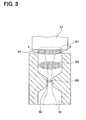
- FIG. 3 is an enlarged cross-sectional view of a portion III of FIG. 2;
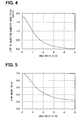
- FIG. 4 is a chart showing an analysis result of a relation between an area ratio (=S1/S2) and a lift to injection-quantity sensitivity of the fuel injection valve according to the one embodiment; and
- FIG. 5 is a chart showing an analysis result of a relation between the area ratio (=S1/S2) and a flow amount ratio of the fuel injection valve according to the one embodiment.
- One embodiment of the present invention is described referring to accompanying drawings. A fuel injection valve is mounted on a cylinder head of an internal combustion engine (more specifically, a diesel engine, which is not shown). The fuel injection valve injects high pressure fuel accumulated in an accumulator (not shown) into a cylinder of the internal combustion engine.
- As shown in FIGS. 1 to 3, a
body 1 of the fuel injection valve includes afuel inlet port 11, into which high pressure fuel from the accumulator is introduced, and afuel outlet port 12, through which the fuel inside the fuel injection valve flows to afuel tank 100. - A
nozzle 2, which injects fuel at a valve opening state, where the valve is opened, is placed at one end of thebody 1 in a longitudinal direction (at one longitudinal end of the body 1). Thenozzle 2 has anozzle needle 21, a nozzle spring 22, and anozzle cylinder 23. Thenozzle needle 21 is slidably held by thebody 1. The nozzle spring 22 biases thenozzle needle 21 in a valve closing direction for closing the valve. Thenozzle cylinder 23 receives apiston portion 21 a of thenozzle needle 21. - At the one longitudinal end of the
body 1,injection orifices 24, which communicate with thefuel inlet port 11 through a high-pressure fuel passage 13, is formed, and it is designed that high pressure fuel is injected through theinjection orifices 24 into the cylinder of the internal combustion engine. A taper-shaped valve seat 25 is formed upstream of theinjection orifices 24, and theinjection orifices 24 are opened or closed by engaging and disengaging aseat portion 21 b, which is formed in thenozzle needle 21, with and from thevalve seat 25. - The
nozzle cylinder 23 slidably and fluid tightly receives a piston portion21 a, and thepiston portion 21 a and thenozzle cylinder 23 defines acontrol chamber 26, in which internal fuel pressure is changed between a high pressure and a low pressure. And thenozzle needle 21 is biased in the valve closing direction by fuel pressure in thecontrol chamber 26, and also thenozzle needle 21 is biased in the valve opening direction for opening the valve (e.g., for opening the injection orifices 24) by high pressure fuel, which is introduced from thefuel inlet port 11 toward theinjection orifices 24 through the high-pressure fuel passage 13. - In a longitudinal intermediate part of the
body 1, a valve chamber14, which receives acontrol valve 3 controlling pressure in thecontrol chamber 26, is formed. Thecontrol chamber 26 is always communicated with thevalve chamber 14 through a communication passage15. - The
valve chamber 14 is connected with thefuel inlet port 11 through the high-pressure fuel passage 13. The high-pressure fuel passage 13 is provided with a high-pressure restrictor 50. Also, thevalve chamber 14 is connected with thefuel outlet port 12 through a low-pressure fuel passage 16. The low-pressure fuel passage 16 is provided with a low-pressure restrictor 60. - The
control valve 3 has avalve element 31 and avalve spring 32. Thevalve element 31 is engaged with and disengaged from a low-pressure seat portion 33 to prohibit and allow communication between thevalve chamber 14 and the low-pressure fuel passage 16, and thevalve element 31 is engaged with and disengaged from a high-pressure seat portion 34 to prohibit and allow communication between thevalve chamber 14 and the high-pressure fuel passage 13. Thevalve spring 32 biases thevalve element 31 in a direction for opening (allowing) the communication between thevalve chamber 14 and the high-pressure fuel passage 13 and at the same time for closing (prohibiting) the communication between thevalve chamber 14 and the low-pressure fuel passage 16. - Here, referring to FIG. 3, S3 > S1 > S2 is satisfied in the following condition. S1 is a passage area the high-
pressure seat portion 34. S2 is a passage area of the high-pressure restrictor 50. S3 is a passage area of the high-pressure fuel passage 13. Typically, the passage area S1 of the high-pressure seat portion 34 is a product of a peripheral length of the high-pressure seat portion 34 multiplied by a lift amount of the valve element 31 (hereinafter, referred as a valve element lift amount) in a state, where thevalve element 31 is disengaged from (is positioned apart from) the high-pressure seat portion 34. For example, the valve element lift amount indicated here is a distance between the end face of thevalve element 31 and the high-pressure seat portion 34 in a direction of displacement of thevalve element 31. Also, the passage area S3 of the high-pressure fuel passage 13 corresponds to a passage area of a part (other than the high-pressure restrictor 50) with a minimum passage area of the high-pressure fuel passage 13, which connects between thefuel inlet port 11 and the high-pressure seat portion 34. - An
actuator chamber 17, which receives anactuator 4 actuating (driving) thecontrol valve 3, is formed at the other longitudinal end of thebody 1. Theactuator chamber 17 is connected to the low-pressure fuel passage 16 through a low-pressure communication passage 16a. - The
actuator 4 includes apiezoelectric stack 41 and a transmission portion. Thepiezoelectric stack 41 has multiple piezoelectric elements, which are laminated onto one another, and expands and contracts by charging and discharging the electric charge. The transmission portion transmits a displacement of thepiezoelectric stack 41, which is caused by the expansion and contraction, to thevalve element 31 of thecontrol valve 3. - The transmission portion is constructed as follows. A
first piston 43 and asecond piston 44 are slidably and fluid tightly received by anactuator cylinder 42, and afluid chamber 45, which is filled with fuel, is provided between thefirst piston 43 and thesecond piston 44. - The
first piston 43 is biased toward thepiezoelectric stack 41 by afirst spring 46, and is driven by thepiezoelectric stack 41 directly. And, at the time of the extension of thepiezoelectric stack 41, pressure in thefluid chamber 45 is raised by thefirst piston 43. - The
second piston 44 is biased toward thevalve element 31 of thecontrol valve 3 by asecond spring 47, and is operated to drive thevalve element 31 by pressure in thefluid chamber 45. At the time of the extension of thepiezoelectric stack 41, pressure in thefluid chamber 45, which is made higher, drives thesecond piston 44 such that the communication between thevalve chamber 14 and the high-pressure fuel passage 13 is prohibited. Along with this, thesecond piston 44 drives thevalve element 31 in a position, where the communication between thevalve chamber 14 and the low-pressure fuel passage 16 is allowed. In contrast, at a time of contraction of thepiezoelectric stack 41, namely when pressure in thefluid chamber 45 is low, thesecond piston 44 resists thesecond spring 47, and is pushed back by thevalve spring 32 of thecontrol valve 3 toward thefirst piston 43. - A
return passage 110 connects thefuel outlet port 12 with thefuel tank 100, and thereturn passage 110 has a back-pressure valve 120 at one side thereof toward the low-pressure fuel passage 16 for controlling pressure in the low-pressure fuel passage 16. By the way, the back-pressure valve 120 controls the pressure in the low-pressure fuel passage 16 at generally 1 MPa whereas pressure in high pressure fuel accumulated in the accumulator is equal to or greater than 100 MPa. - An electric power is supplied through a
piezoelectric drive circuit 130 to thepiezoelectric stack 41. Electrification timing of thepiezoelectric drive circuit 130 to thepiezoelectric stack 41 is controlled by an electronic control circuit (hereinafter, referred as ECU) 140. - The
ECU 140 includes a known microcomputer having a CPU, ROM, an EEPROM, and a RAM, all of which are not illustrated, and executes computing processes in accordance with programs stored in the microcomputer. Signals are inputted into theECU 140 through various sensors (not shown) detecting an intake air amount, a depression amount of an accelerator pedal, a rotational speed of the internal combustion engine, and fuel pressure in the accumulator. - An operation of the fuel injection valve is described below. When the
piezoelectric stack 41 is energized, thepiezoelectric stack 41 expands and thefirst piston 43 is driven to raise pressure in thefluid chamber 45. Thesecond piston 44 is driven toward thevalve element 31 of thecontrol valve 3 by pressure in thefluid chamber 45, which is thus made higher. - Then, because the
valve element 31 is driven with thesecond piston 44, thevalve element 31 contacts with (is engaged with) the high-pressure seat portion 34 such that the communication between thevalve chamber 14 and the high-pressure fuel passage 13 is prohibited. Along with this, thevalve element 31 is placed apart from (is disengaged from) the low-pressure seat portion 33 such that the communication between thevalve chamber 14 and the low-pressure fuel passage 16 is allowed. Thus, fuel in thecontrol chamber 26 is returned to thefuel tank 100 through thecommunication passage 15, thevalve chamber 14, the low-pressure restrictor 60, and the low-pressure fuel passage 16. - Due to this, pressure in the
control chamber 26 falls and the force biasing thenozzle needle 21 in the valve closing direction is reduced. Thus, thenozzle needle 21 moves in the valve opening direction so that theseat portion 21 b is disengaged from thevalve seat 25. As a result, theinjection orifices 24 are opened, and fuel is injected into the cylinder of the internal combustion engine through the injection orifices 24. - After this, when energization to the
piezoelectric stack 41 is stopped, thepiezoelectric stack 41 contracts, and therefore thefirst piston 43 is returned toward thepiezoelectric stack 41 by thefirst spring 46. Also, by thevalve spring 32, thevalve element 31 and thesecond piston 44 are returned toward thefirst piston 43. - Due to this, the
valve element 31 is separated apart from (is disengaged from) the high-pressure seat portion 34 such that the communication between thevalve chamber 14 and the high-pressure fuel passage 13 is allowed. Along with this, thevalve element 31 contacts with (is engaged with) the low-pressure seat portion 33 such that the communication between thevalve chamber 14 and the low-pressure fuel passage 16 is prohibited. Thus, high pressure fuel from the accumulator is introduced into thecontrol chamber 26 through the high-pressure fuel passage 13, the high-pressure restrictor 50, thevalve chamber 14, and thecommunication passage 15. - As a result, pressure in the
control chamber 26 rises, and therefore, a biasing force that biases thenozzle needle 21 in the valve closing direction becomes larger. Therefore, thenozzle needle 21 moves in the valve closing direction, and theseat portion 21 b seats on (is engaged with) thevalve seat 25 such that theinjection orifices 24 are closed. Thus, the fuel injection is finished. - Here, because S1 > S2 is satisfied, a flow amount of fuel flowing into the
control chamber 26 per unit time (fuel inlet velocity) is determined mainly by the passage area S2 of the high-pressure restrictor 50. As a result, this reduces the change of the injection quantity due to a change with time of the valve element lift amount. Also, the passage area S1 of the high-pressure seat portion 34 and the passage area S2 of the high-pressure restrictor 50 are made smaller than the passage area S3 of the high-pressure fuel passage 13. In other words, because double restrictors (e.g., the high-pressure seat portion 34 and the high-pressure restrictor 50) are provided, a large decrease of the fuel inlet velocity can be limited. - FIG. 4 is a chart showing an analysis result of a relation between an area ratio (=S1/S2) and a lift to injection-quantity sensitivity of the fuel injection valve according to the present embodiment. Here, the passage area S1 of the high-
pressure seat portion 34 is fixed, and the passage area S2 of the high-pressure restrictor 50 is changed such that the area ratio is accordingly set. In the analysis, firstly, in the fuel injection valve of each area ratio, the valve element lift amount is set at 21 "m as an initial state. Then, an injection condition for evaluation is set for the fuel injection valve of each area ratio under the initial state as an injection condition, where the injection quantity is targeted at 80 mm3/st. While each fuel injection valve is operated under the injection condition for evaluation, the valve element lift amount is increased. At this time, an amount of decrease in the injection quantity per the increase of the valve element lift amount of 1 "m is analyzed. In FIG. 4, a horizontal axis indicates the above set area ratio, and a vertical axis indicates the lift to injection-quantity sensitivity, which corresponds to the above analyzed amount of decrease in the injection quantity. - As shown in FIG. 4, by enlarging the area ratio, the lift to injection-quantity sensitivity is reduced. When a change of the valve element lift amount due to the change with time (e.g., an aged deterioration) of an apparatus of an actual use is considered, 1.5 ≤ S1/S2 is required.
- FIG. 5 is a chart showing an analysis result of a relation between the area ratio (=S1/S2) and a flow amount ratio of the fuel injection valve according to the present embodiment. For example, the flow amount ratio is a ratio of the fuel inlet velocity at each area ratio relative to a fuel inlet velocity in a case, where the high-
pressure restrictor 50 is not provided. - As shown in FIG. 5, when the area ratio is enlarged, the flow amount ratio is reduced. When the flow amount ratio is substantially reduced, the valve closing speed of the
nozzle needle 21 may disadvantageously reduced. Thus, in practical use, S1/S2 ≤ 2.5 is required, and S1/S2 ≤ 2 is more required. - Therefore, when the lift to injection-quantity sensitivity and the valve closing speed of the
nozzle needle 21 are considered, 1.5 ≤ S1/S2 ≤ 2.5 is required. Furthermore, 1.5 ≤ S1/S2 ≤ 2 is more required. As a result, the valve closing speed of thenozzle needle 21 is reliably limited from greatly decreasing, and at the same time, this reliably reduces the change of the injection quantity due to the change with time of the valve element lift amount. - Additional advantages and modifications will readily occur to those skilled in the art. The invention in its broader terms is therefore not limited to the specific details, representative apparatus, and illustrative examples shown and described.
- A fuel injection valve includes a valve element (31), an actuator (4), a control chamber (26), and a nozzle (2). The valve element (31) is provided in a valve chamber (14). The control chamber (26) is always communicated with the valve chamber (14). S3 > S1 > S2 is satisfied in a condition, where the followings are satisfied. S1 is a passage area of a high-pressure seat portion (34) of the valve chamber, which area is a product of a peripheral length of the high-pressure seat portion (34) multiplied by a lift amount of the valve element (31) in a state, where the valve element (31) is disengaged from the high-pressure seat portion (34). S2 is a passage area of the high-pressure restrictor (50). S3 is a passage area of the high-pressure fuel passage (13).
Claims (3)
- A fuel injection valve comprising:a valve element (31) that is provided in a valve chamber (14), wherein:the valve element (31) is engaged with and disengaged from a low-pressure seat portion (33) of the valve chamber (14) to prohibit and allow communication between the valve chamber (14) and a low-pressure fuel passage (16); andthe valve element (31) is engaged with and disengaged from a high-pressure seat portion (34) of the valve chamber (14) to prohibit and allow communication between the valve chamber (14) and a high-pressure fuel passage (13);an actuator (4) that actuates the valve element (31);a control chamber (26) that is always communicated with the valve chamber (14); anda nozzle (2) that has a nozzle needle (21) for opening and closing an injection orifice (24), wherein the nozzle needle (21) is biased in a valve closing direction for closing the injection orifice (24) by fuel pressure in the control chamber (26), wherein:the high-pressure fuel passage (13) is provided with a high-pressure restrictor (50); andS3 > S1 > S2 is satisfied in a condition, where the followings are satisfied:S1 is a passage area of the high-pressure seat portion (34), which area is a product of a peripheral length of the high-pressure seat portion (34) multiplied by a lift amount of the valve element (31) in a state, where the valve element (31) is disengaged from the high-pressure seat portion (34);S2 is a passage area of the high-pressure restrictor (50); andS3 is a passage area of the high-pressure fuel passage (13).
- The fuel injection valve according to claim 1, wherein:1.5 ≤ S1/S2 ≤ 2.5 is satisfied.
- The fuel injection valve according to claim 2, wherein:1.5 ≤ S1/S2 ≤ 2 is satisfied.
Applications Claiming Priority (1)
| Application Number | Priority Date | Filing Date | Title |
|---|---|---|---|
| JP2006170955A JP2008002306A (en) | 2006-06-21 | 2006-06-21 | Fuel injection valve |
Publications (1)
| Publication Number | Publication Date |
|---|---|
| EP1870594A1 true EP1870594A1 (en) | 2007-12-26 |
Family
ID=38512184
Family Applications (1)
| Application Number | Title | Priority Date | Filing Date |
|---|---|---|---|
| EP07110200A Withdrawn EP1870594A1 (en) | 2006-06-21 | 2007-06-13 | Fuel injection valve |
Country Status (4)
| Country | Link |
|---|---|
| US (1) | US20070295306A1 (en) |
| EP (1) | EP1870594A1 (en) |
| JP (1) | JP2008002306A (en) |
| CN (1) | CN101092921A (en) |
Cited By (5)
| Publication number | Priority date | Publication date | Assignee | Title |
|---|---|---|---|---|
| CH704454A1 (en) * | 2011-02-08 | 2012-08-15 | Liebherr Machines Bulle Sa | Injection apparatus for a fluid. |
| EP2541035A1 (en) * | 2011-06-30 | 2013-01-02 | Robert Bosch Gmbh | Fuel injector |
| WO2016059079A1 (en) * | 2014-10-15 | 2016-04-21 | Continental Automotive Gmbh | Injection valve for injecting fluid into a combustion chamber of an internal combustion engine |
| WO2016075089A1 (en) * | 2014-11-11 | 2016-05-19 | Robert Bosch Gmbh | An injection valve having control chamber |
| WO2018141335A1 (en) * | 2017-02-01 | 2018-08-09 | L'orange Gmbh | Fuel injector for an internal combustion engine |
Families Citing this family (3)
| Publication number | Priority date | Publication date | Assignee | Title |
|---|---|---|---|---|
| DE102009047611A1 (en) | 2009-12-08 | 2011-06-09 | Robert Bosch Gmbh | Fuel injection device with needle position determination |
| JP6296948B2 (en) * | 2014-09-02 | 2018-03-20 | 株式会社デンソー | Fuel injection valve |
| JP6766711B2 (en) * | 2017-03-17 | 2020-10-14 | 株式会社デンソー | Fuel injection device |
Citations (4)
| Publication number | Priority date | Publication date | Assignee | Title |
|---|---|---|---|---|
| DE19729844A1 (en) * | 1997-07-11 | 1999-01-14 | Bosch Gmbh Robert | Fuel injector |
| WO1999061779A1 (en) * | 1998-05-28 | 1999-12-02 | Siemens Aktiengesellschaft | Fuel injection valve for internal combustion engines |
| WO2003004864A1 (en) * | 2001-06-29 | 2003-01-16 | Robert Bosch Gmbh | Fuel injector switch valve for the compression/decompression of a control chamber |
| DE102004030445A1 (en) * | 2004-06-24 | 2006-01-12 | Robert Bosch Gmbh | Fuel injector |
-
2006
- 2006-06-21 JP JP2006170955A patent/JP2008002306A/en not_active Withdrawn
-
2007
- 2007-06-13 EP EP07110200A patent/EP1870594A1/en not_active Withdrawn
- 2007-06-14 US US11/808,994 patent/US20070295306A1/en not_active Abandoned
- 2007-06-20 CN CNA2007101119130A patent/CN101092921A/en active Pending
Patent Citations (4)
| Publication number | Priority date | Publication date | Assignee | Title |
|---|---|---|---|---|
| DE19729844A1 (en) * | 1997-07-11 | 1999-01-14 | Bosch Gmbh Robert | Fuel injector |
| WO1999061779A1 (en) * | 1998-05-28 | 1999-12-02 | Siemens Aktiengesellschaft | Fuel injection valve for internal combustion engines |
| WO2003004864A1 (en) * | 2001-06-29 | 2003-01-16 | Robert Bosch Gmbh | Fuel injector switch valve for the compression/decompression of a control chamber |
| DE102004030445A1 (en) * | 2004-06-24 | 2006-01-12 | Robert Bosch Gmbh | Fuel injector |
Cited By (5)
| Publication number | Priority date | Publication date | Assignee | Title |
|---|---|---|---|---|
| CH704454A1 (en) * | 2011-02-08 | 2012-08-15 | Liebherr Machines Bulle Sa | Injection apparatus for a fluid. |
| EP2541035A1 (en) * | 2011-06-30 | 2013-01-02 | Robert Bosch Gmbh | Fuel injector |
| WO2016059079A1 (en) * | 2014-10-15 | 2016-04-21 | Continental Automotive Gmbh | Injection valve for injecting fluid into a combustion chamber of an internal combustion engine |
| WO2016075089A1 (en) * | 2014-11-11 | 2016-05-19 | Robert Bosch Gmbh | An injection valve having control chamber |
| WO2018141335A1 (en) * | 2017-02-01 | 2018-08-09 | L'orange Gmbh | Fuel injector for an internal combustion engine |
Also Published As
| Publication number | Publication date |
|---|---|
| JP2008002306A (en) | 2008-01-10 |
| US20070295306A1 (en) | 2007-12-27 |
| CN101092921A (en) | 2007-12-26 |
Similar Documents
| Publication | Publication Date | Title |
|---|---|---|
| EP1865190B1 (en) | Fuel injection valve | |
| EP1870594A1 (en) | Fuel injection valve | |
| US20130001327A1 (en) | High-pressure fuel injection valve for an internal combustion engine | |
| JP5482717B2 (en) | Fuel injection control device for internal combustion engine | |
| CN101910605A (en) | Reduces time-dependent variation in operation of engine and control valve components | |
| US7275522B2 (en) | Method and apparatus for controlling a valve, and method and apparatus for controlling a pump-nozzle apparatus with the valve | |
| US20100006676A1 (en) | Fuel injection apparatus | |
| WO2007141970A1 (en) | Valve drive device of internal combustion engine | |
| US7353806B2 (en) | Fuel injector with pressure balancing valve | |
| JP2004517254A (en) | Injection valve | |
| US20130048751A1 (en) | Method and device for operating an injection valve | |
| WO2007084243A2 (en) | Fuel injector with selectable intensification | |
| EP1793117B1 (en) | Fuel injection device | |
| JP2004537001A (en) | Liquid control valve | |
| US20090126689A1 (en) | Fuel injector having valve with opposing sealing surfaces | |
| JP4618257B2 (en) | Fuel injection valve | |
| JP2011122463A (en) | Fuel injection valve | |
| KR20070108056A (en) | Injector for internal combustion engine | |
| JP4591436B2 (en) | Fuel injection device | |
| JPH10281038A (en) | Fuel injection valve | |
| JP2004137990A (en) | Accumulation type fuel injection device | |
| US7770818B2 (en) | Fuel injection valve | |
| JP2011122464A (en) | Fuel injection valve | |
| JP2010242566A (en) | Fuel injection system | |
| WO2007117193A1 (en) | Injection means for a combustion engine |
Legal Events
| Date | Code | Title | Description |
|---|---|---|---|
| PUAI | Public reference made under article 153(3) epc to a published international application that has entered the european phase |
Free format text: ORIGINAL CODE: 0009012 |
|
| AK | Designated contracting states |
Kind code of ref document: A1 Designated state(s): AT BE BG CH CY CZ DE DK EE ES FI FR GB GR HU IE IS IT LI LT LU LV MC MT NL PL PT RO SE SI SK TR |
|
| AX | Request for extension of the european patent |
Extension state: AL BA HR MK YU |
|
| AKX | Designation fees paid | ||
| STAA | Information on the status of an ep patent application or granted ep patent |
Free format text: STATUS: THE APPLICATION IS DEEMED TO BE WITHDRAWN |
|
| 18D | Application deemed to be withdrawn |
Effective date: 20080627 |
|
| REG | Reference to a national code |
Ref country code: DE Ref legal event code: 8566 |