EP1870531A2 - Reinforcement for cast-in-place rib - Google Patents
Reinforcement for cast-in-place rib Download PDFInfo
- Publication number
- EP1870531A2 EP1870531A2 EP07380171A EP07380171A EP1870531A2 EP 1870531 A2 EP1870531 A2 EP 1870531A2 EP 07380171 A EP07380171 A EP 07380171A EP 07380171 A EP07380171 A EP 07380171A EP 1870531 A2 EP1870531 A2 EP 1870531A2
- Authority
- EP
- European Patent Office
- Prior art keywords
- stirrups
- rib
- reinforcement
- round bars
- separator
- Prior art date
- Legal status (The legal status is an assumption and is not a legal conclusion. Google has not performed a legal analysis and makes no representation as to the accuracy of the status listed.)
- Withdrawn
Links
Images



Classifications
-
- E—FIXED CONSTRUCTIONS
- E04—BUILDING
- E04C—STRUCTURAL ELEMENTS; BUILDING MATERIALS
- E04C5/00—Reinforcing elements, e.g. for concrete; Auxiliary elements therefor
- E04C5/16—Auxiliary parts for reinforcements, e.g. connectors, spacers, stirrups
- E04C5/162—Connectors or means for connecting parts for reinforcements
- E04C5/163—Connectors or means for connecting parts for reinforcements the reinforcements running in one single direction
-
- E—FIXED CONSTRUCTIONS
- E04—BUILDING
- E04C—STRUCTURAL ELEMENTS; BUILDING MATERIALS
- E04C5/00—Reinforcing elements, e.g. for concrete; Auxiliary elements therefor
- E04C5/01—Reinforcing elements of metal, e.g. with non-structural coatings
- E04C5/06—Reinforcing elements of metal, e.g. with non-structural coatings of high bending resistance, i.e. of essentially three-dimensional [3D] extent, e.g. lattice girders
- E04C5/0604—Prismatic or cylindrical reinforcement cages composed of longitudinal bars and open or closed stirrup rods
- E04C5/0622—Open cages, e.g. connecting stirrup baskets
-
- E—FIXED CONSTRUCTIONS
- E04—BUILDING
- E04C—STRUCTURAL ELEMENTS; BUILDING MATERIALS
- E04C5/00—Reinforcing elements, e.g. for concrete; Auxiliary elements therefor
- E04C5/16—Auxiliary parts for reinforcements, e.g. connectors, spacers, stirrups
- E04C5/168—Spacers connecting parts for reinforcements and spacing the reinforcements from the form
-
- E—FIXED CONSTRUCTIONS
- E04—BUILDING
- E04C—STRUCTURAL ELEMENTS; BUILDING MATERIALS
- E04C5/00—Reinforcing elements, e.g. for concrete; Auxiliary elements therefor
- E04C5/16—Auxiliary parts for reinforcements, e.g. connectors, spacers, stirrups
- E04C5/20—Auxiliary parts for reinforcements, e.g. connectors, spacers, stirrups of material other than metal or with only additional metal parts, e.g. concrete or plastics spacers with metal binding wires
- E04C5/205—Ladder or strip spacers
Definitions
- the reinforcement is formed with the number of stirrups established through the calculation of the shear stress, with the necessary longitudinal round bars and with the separator-positioner, which is used to fix the longitudinal round bars to the stirrups and which at the same time prevents the movement of the entire reinforcement formed by the stirrups and the round bars inside the rib during the concrete pouring.
Landscapes
- Engineering & Computer Science (AREA)
- Architecture (AREA)
- Civil Engineering (AREA)
- Structural Engineering (AREA)
- Forms Removed On Construction Sites Or Auxiliary Members Thereof (AREA)
- Electric Propulsion And Braking For Vehicles (AREA)
Abstract
Reinforcement for a reinforced concrete rib being composed of several stirrups (1) joined by their lower part via a round bar (2) having only a binding function. Inside the stirrups (1) longitudinal round bars (4,5) are placed, there round bars (4,5) being bound to the stirrup (1) via a separator-positioner (6) having a width slightly smaller than that of the rib.
Description
- This descriptive report refers to a reinforcement for cast-in-place rib that can be used in one-way and two-way slabs, which improves the existing reinforcements because of its technical quality in regards to the applicable regulation for the calculation of reinforced concrete, and because of being inexpensive for the manufacturer due to offering the possibility of manufacturing the stirrups joined, and for the user because of the ease of installation and for being inexpensive.
- The field of application of this invention is in the construction industry and particularly in relation to the execution of one-way and two-way slabs.
- This patent is related to what is referred to as separator-positioner of the longitudinal round bars in Patent 200003006 by the same inventor. As for open or closed stirrups, this is part of the current knowledge. The patent adds to the shape of the stirrups the final vertical fold which separates the stirrup from its support and improves the anchoring of the horizontal branch. It also adds as a fundamental aspect that the stirrups are joined in their lower part with a welded round bar or an equivalent joining method, which will enable its automatic manufacturing and handling, apart from facilitating its installation in the works. We do not know of any background in relation to these characteristics.
- The reinforcement is formed with the number of stirrups established through the calculation of the shear stress, with the necessary longitudinal round bars and with the separator-positioner, which is used to fix the longitudinal round bars to the stirrups and which at the same time prevents the movement of the entire reinforcement formed by the stirrups and the round bars inside the rib during the concrete pouring.
- The stirrups are based on those of the open or closed types, widely known and used in construction, but with the addition from this invention, as a first improvement, of the fact that they end in a fold which raises them from the hollow block or weight-reduction element on which they are supported, and with the second improvement that they are joined in their lower part through a round bar, in groups whose number is determined by reinforced concrete calculations. In this way, the manufacturing, handling and installation is very simple. Once the group of stirrups is placed, the number of longitudinal round bars established through calculation are placed inside of them and they are fixed with the piece which we call separator-positioner.
- To supplement this description and in order to assist in the understanding of the invention, we attach to this descriptive report a set of blueprints in which we have portrayed the following as an illustration but not as a limitation:
- Figure 1. Elevation view of open stirrup finished in an angle (1) which serves to separate it from the hollow block or weight-reducing element where it is supported (3) (3').
- Figure 2. Elevation view of the separator-positioner (6).
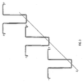
- Figure 3. Perspective view of three stirrups (1, 1', 1") joined by their lower part with a round bar (2).
- Figure 4. Section view of a rib where we can see the the stirrup supported (1) on the weight-reducing element (3) (3'), two longitudinal round bars (4) and (5), the round bar (2) which unites the stirrups by their lower parts and the separator-positioner (6) from Figure 2.
- Figure 6. Section view of a rib where we can see the stirrup supported (1) on the weight-reducing element (3) (3'), two longitudinal round bars (4') and (5'), in this case placed inside the middle part of the separator-positioner, the round bar (2) which binds the stirrups by their lower part and the separator-positioner (6) from Figure 2.
- The hollow blocks or weight-reducing elements (3) (3') are placed, and between them the stirrups (1) are placed, united via the round bar (2) in the number and separation established by calculations, then the round bars which compose the traction reinforcement of the rib are introduced, and finally the separators-positioners (6) are placed as in Figure 2, which serve to fix the round bars (4) and (5) the stirrups (1) and to prevent their (1) lateral movement during the pouring of concrete, which concludes the operation of creating the rib and leaving it ready for the pouring of concrete. The separator-positioner (6) has a similar size (slightly smaller) than the width of the rib where it is placed.
- Following Figure 5 the sequence is the same as for Figure 4, except that the round bars (4') and (5') are placed in the central part of the separator-positioner, as seen in Figure 5. The stirrup (1) is narrower than that from Figure 4, without this indicating a loss of generality.
Claims (3)
- Reinforcement for reinforced concrete rib with the characteristic of being composed of several stirrups united by their lower part via a round bar which does not have any resistance function, just a binding function. Inside the stirrups, the longitudinal round bars are placed, whose quantity and diameter shall be determined through calculation and these round bars are bound to a stirrup, through the separator-positioner with a width slightly lower than that of the rib.
- Reinforcement for reinforced concrete rib as per the first claim, with the characteristic that the stirrups, open or closed, supported by the weight-reducing elements of the slab, end in an angle in order to separate them from the weight-reducing element.
- Reinforcement for reinforced concrete rib, as per the first and second claims, with the characteristic that the separator-positioner serves to fix the round bars, and prevent the lateral movement of the stirrups during the pouring of concrete, because of their size which is similar to the width of the rib on which they are placed.
Applications Claiming Priority (1)
| Application Number | Priority Date | Filing Date | Title |
|---|---|---|---|
| ES200601674A ES2282047B1 (en) | 2006-06-21 | 2006-06-21 | ARMOR FOR NERVIO IN SITU. |
Publications (1)
| Publication Number | Publication Date |
|---|---|
| EP1870531A2 true EP1870531A2 (en) | 2007-12-26 |
Family
ID=38512284
Family Applications (1)
| Application Number | Title | Priority Date | Filing Date |
|---|---|---|---|
| EP07380171A Withdrawn EP1870531A2 (en) | 2006-06-21 | 2007-06-12 | Reinforcement for cast-in-place rib |
Country Status (2)
| Country | Link |
|---|---|
| EP (1) | EP1870531A2 (en) |
| ES (1) | ES2282047B1 (en) |
Family Cites Families (6)
| Publication number | Priority date | Publication date | Assignee | Title |
|---|---|---|---|---|
| US1708352A (en) * | 1929-04-09 | barton | ||
| US1379625A (en) * | 1918-07-05 | 1921-05-31 | Rudolph B Hartman | Reinforced concrete construction |
| US1342349A (en) * | 1919-01-29 | 1920-06-01 | Orvin Johan Eilert | Support-strap for reinforcement in steel-concrete girders |
| US1909121A (en) * | 1930-01-29 | 1933-05-16 | William M Crane Jr | Spacing reenforcement for concrete structures |
| ES2174742B1 (en) * | 2000-12-22 | 2003-10-16 | Garay Olatz Isabel Merino | SEPARATOR-POSITIONER OF FERRALLA ARMORS FOR THE CONSTRUCTION OF UNIDIRECTIONAL AND BIDIRECTIONAL FORGINGS. |
| ES2245244B1 (en) * | 2004-06-08 | 2007-02-16 | Ramon Mimenza Larracoechea | SYSTEM OF CONSTRUCTION OF SOILS OF FORGED UNIDIRECTIONAL AND BIDIRECTIONAL DRAWINGS. |
-
2006
- 2006-06-21 ES ES200601674A patent/ES2282047B1/en not_active Expired - Fee Related
-
2007
- 2007-06-12 EP EP07380171A patent/EP1870531A2/en not_active Withdrawn
Also Published As
| Publication number | Publication date |
|---|---|
| ES2282047B1 (en) | 2009-05-05 |
| ES2282047A1 (en) | 2007-10-01 |
Similar Documents
| Publication | Publication Date | Title |
|---|---|---|
| KR101519086B1 (en) | Bridg using t-girder with pile supporting apparatus and bridge continuous construction method using the same | |
| CN207063153U (en) | A kind of sleeve grouting formula reinforced concrete precast assembling bean column node | |
| CN106759865B (en) | A CFST column-U-shaped steel plate composite beam frame | |
| KR20150144398A (en) | Reinforced Concrete Walls by Triangular Reinforcing Bar Details and Construction Method Thereof | |
| CN105064614A (en) | Stirrup capable of providing transverse constraining force for longitudinal bar and manufacturing method of stirrup | |
| US20130174499A1 (en) | Reinforcing Bracket for Lifting Anchors in Reinforced Concrete Walls | |
| US20190177977A1 (en) | Sleeve for coupling reinforcing bar and a method of using the same | |
| EP1870531A2 (en) | Reinforcement for cast-in-place rib | |
| JP2001020454A (en) | Reinforced baskets by non-welding in structures such as foundation piles and method of manufacturing the same | |
| CN110042936A (en) | A kind of concrete construction joint portion structure Enhancement Method | |
| KR100922645B1 (en) | Cap assembly of pile | |
| CN208363287U (en) | A kind of connecting node of steel column/beam and prefabricated board | |
| KR100873846B1 (en) | Reinforcing bar assembly | |
| KR101970873B1 (en) | Steel composite hollow core slab with topping concrete | |
| JP2011080316A (en) | Joining method of concrete structures | |
| Ferreira et al. | Influence of stirrup detailing on the punching resistance of reinforced concrete flat slabs | |
| JP6324105B2 (en) | Concrete splicing method | |
| CN111335364A (en) | A construction method for the steel structure at the place where the steel plate waterstop meets the concrete outer wall column | |
| CN212421730U (en) | Sandwich panel components, vertical moulds and forming systems for sandwich panel components | |
| EP1760218A2 (en) | Stirrups for the construction of rebar reinforcements for reinforced concrete beams | |
| JPH06280315A (en) | Joint of precast concrete member and its joint member | |
| KR102118589B1 (en) | Reinforcing device of pile head part and method of pile structure construction method therewith | |
| KR101625141B1 (en) | the steel frame and reinforced concrete hybrid rahmen precast concrete structure for the torsion of girder support | |
| JP3996110B2 (en) | Manufacturing method of precast concrete board. | |
| CN209260956U (en) | Wall and foundation connection structure and assembled arthitecutral structure system |
Legal Events
| Date | Code | Title | Description |
|---|---|---|---|
| PUAI | Public reference made under article 153(3) epc to a published international application that has entered the european phase |
Free format text: ORIGINAL CODE: 0009012 |
|
| 17P | Request for examination filed |
Effective date: 20070626 |
|
| AK | Designated contracting states |
Kind code of ref document: A2 Designated state(s): AT BE BG CH CY CZ DE DK EE ES FI FR GB GR HU IE IS IT LI LT LU LV MC MT NL PL PT RO SE SI SK TR |
|
| AX | Request for extension of the european patent |
Extension state: AL BA HR MK YU |
|
| STAA | Information on the status of an ep patent application or granted ep patent |
Free format text: STATUS: THE APPLICATION IS DEEMED TO BE WITHDRAWN |
|
| 18D | Application deemed to be withdrawn |
Effective date: 20120103 |