EP1869780B1 - Apparatus and method for determining sleep clock timing - Google Patents
Apparatus and method for determining sleep clock timing Download PDFInfo
- Publication number
- EP1869780B1 EP1869780B1 EP06737617A EP06737617A EP1869780B1 EP 1869780 B1 EP1869780 B1 EP 1869780B1 EP 06737617 A EP06737617 A EP 06737617A EP 06737617 A EP06737617 A EP 06737617A EP 1869780 B1 EP1869780 B1 EP 1869780B1
- Authority
- EP
- European Patent Office
- Prior art keywords
- frequency
- sleep
- estimate
- clock
- sleep clock
- Prior art date
- Legal status (The legal status is an assumption and is not a legal conclusion. Google has not performed a legal analysis and makes no representation as to the accuracy of the status listed.)
- Not-in-force
Links
Images


Classifications
-
- H—ELECTRICITY
- H04—ELECTRIC COMMUNICATION TECHNIQUE
- H04W—WIRELESS COMMUNICATION NETWORKS
- H04W52/00—Power management, e.g. TPC [Transmission Power Control], power saving or power classes
- H04W52/02—Power saving arrangements
- H04W52/0209—Power saving arrangements in terminal devices
- H04W52/0261—Power saving arrangements in terminal devices managing power supply demand, e.g. depending on battery level
- H04W52/0287—Power saving arrangements in terminal devices managing power supply demand, e.g. depending on battery level changing the clock frequency of a controller in the equipment
- H04W52/029—Power saving arrangements in terminal devices managing power supply demand, e.g. depending on battery level changing the clock frequency of a controller in the equipment reducing the clock frequency of the controller
-
- H—ELECTRICITY
- H04—ELECTRIC COMMUNICATION TECHNIQUE
- H04J—MULTIPLEX COMMUNICATION
- H04J1/00—Frequency-division multiplex systems
-
- H—ELECTRICITY
- H04—ELECTRIC COMMUNICATION TECHNIQUE
- H04L—TRANSMISSION OF DIGITAL INFORMATION, e.g. TELEGRAPHIC COMMUNICATION
- H04L7/00—Arrangements for synchronising receiver with transmitter
- H04L7/02—Speed or phase control by the received code signals, the signals containing no special synchronisation information
- H04L7/033—Speed or phase control by the received code signals, the signals containing no special synchronisation information using the transitions of the received signal to control the phase of the synchronising-signal-generating means, e.g. using a phase-locked loop
-
- Y—GENERAL TAGGING OF NEW TECHNOLOGICAL DEVELOPMENTS; GENERAL TAGGING OF CROSS-SECTIONAL TECHNOLOGIES SPANNING OVER SEVERAL SECTIONS OF THE IPC; TECHNICAL SUBJECTS COVERED BY FORMER USPC CROSS-REFERENCE ART COLLECTIONS [XRACs] AND DIGESTS
- Y02—TECHNOLOGIES OR APPLICATIONS FOR MITIGATION OR ADAPTATION AGAINST CLIMATE CHANGE
- Y02D—CLIMATE CHANGE MITIGATION TECHNOLOGIES IN INFORMATION AND COMMUNICATION TECHNOLOGIES [ICT], I.E. INFORMATION AND COMMUNICATION TECHNOLOGIES AIMING AT THE REDUCTION OF THEIR OWN ENERGY USE
- Y02D30/00—Reducing energy consumption in communication networks
- Y02D30/70—Reducing energy consumption in communication networks in wireless communication networks
Definitions
- the present disclosure relates to methods and apparatus for estimating a sleep clock frequency and, more particularly, estimating a sleep clock frequency using a combiner to selectively determine an estimate of the sleep clock frequency.
- TCXOs temperature controlled crystal oscillators
- TCXOs In order to improve the battery life of a mobile device, it is known to place most current consuming units within the device into a power saving mode and maintain the system time using low-power sleep circuits. Because of the high current draw of TCXOs, it is not energy efficient to use such devices to maintain system time for sleep circuits. Accordingly, it is known to maintain system timing during sleep or power saving modes using by using a sleep controller having a much lower power usage (e.g., a clock with a current draw of 200 pA) and a lower frequency (e.g., 30-60 kHz) than TCXO devices, which operate a higher frequency (e.g., 44-66 MHz).
- a sleep controller having a much lower power usage (e.g., a clock with a current draw of 200 pA) and a lower frequency (e.g., 30-60 kHz) than TCXO devices, which operate a higher frequency (e.g., 44-66 MHz).
- the slow clock is a low accuracy, free running crystal without temperature compensation
- the system time may drift during sleep. Accordingly, it is desirable to account for this drift and thus determine a maximum sleep time that may be set for the mobile device so that there is no need for re-acquisition of system time on wakeup.
- the sleep clock is used as a timer during sleep, it is necessary to have a good estimate of the sleep clock frequency before going to sleep.
- determining system timing using CDMA PN codes may not be available for determining timing.
- determining an estimate of the sleep clock using the fast clock may yield a very accurate estimate of the sleep clock frequency, but does not account for the change or error due to drift of the sleep clock.
- the sleep clock frequency is accurately determined and the error or drift of the sleep frequency is determined, how to combine this information to yield an accurate result has not been contemplated in the known art.
- WO 02/47281 A1 discloses techniques for compensating for frequency drift in a low frequency clock employed during a sleep period between paging slots within a mobile station of a mobile communications system.
- the correction of a frequency error in the low frequency clock can be done by comparing the measurement of a high frequency clock to that of the low frequency clock when the high frequency clock is active (not sleep periods).
- an apparatus for determining a frequency estimate of a sleep clock.
- the apparatus includes a sleep clock frequency estimator configured to output a fast clock derived sleep clock frequency estimate; a sleep clock change frequency estimator configured to output an estimate of a change in frequency of the sleep clock; and a combiner configured to weight at least one of the fast clock derived sleep clock frequency estimate to obtain a weighted sleep clock frequency estimate and the estimate of the change in frequency of the sleep clock to obtain a weighted estimate of the change in frequency of the sleep clock, and to determine at least one new estimate of the sleep clock frequency using at least one of the weighted sleep clock frequency estimate and the weighted estimate of the change in frequency of the sleep clock.
- a processing circuit for estimating a sleep clock frequency for use in a wireless transceiver system includes a sleep clock frequency estimator configured to output a fast clock derived sleep clock frequency estimate; a sleep clock change frequency estimator configured to output an estimate of a change in frequency of the sleep clock; a combiner configured to selectively weight at least one of the fast clock derived sleep clock frequency estimate to obtain a weighted sleep clock frequency estimate and the estimate of the change in frequency of the sleep clock to obtain a weighted estimate of the change in frequency of the sleep clock, and to determine at least one new estimate of the sleep clock frequency using at least one of the weighted sleep clock frequency estimate and the weighted estimate of the change in frequency of the sleep clock; a memory device configured to store the at least one new estimate of the slow clock frequency weighting estimate; and a processor configured to read the at least one new estimate from the memory device and calculate a system sleep time based on the at least one new estimate prior to entering the system into a sleep mode.
- a wireless device for use in a mobile communications network.
- the device includes a sleep clock frequency estimator configured to output a fast clock derived sleep clock frequency estimate; a sleep clock change frequency estimator configured to output an estimate of a change in frequency of the sleep clock; a combiner configured to selectively weight at least one of the fast clock derived sleep clock frequency estimate to obtain a weighted sleep clock frequency estimate and the estimate of the change in frequency of the sleep clock to obtain a weighted estimate of the change in frequency of the sleep clock, and to determine at least one new estimate of the sleep clock frequency using at least one of the weighted sleep clock frequency estimate and the weighted estimate of the change in frequency of the sleep clock; a memory device configured to store the at least one new estimate of the slow clock frequency weighting estimate; and a processor configured to read the at least one new estimate from the memory device and calculate a sleep time of the wireless device based on the at least one new estimate prior to entering the system into a sleep mode.
- a method for estimating the frequency of a sleep clock includes estimating a change in sleep clock frequency; determining a weighted estimated change in sleep clock frequency using a calculated coefficient to weight the value of the sleep clock frequency change; determining a new estimate for sleep clock frequency using the weighted estimated change in sleep clock frequency and a previous estimated sleep clock frequency and storing the new estimate in a memory device; estimating a sleep clock frequency using a fast clock; determining a weighted estimated sleep clock frequency using at least another calculated coefficient to weight the value of the estimated sleep clock frequency; determining a further new estimate for sleep clock frequency using weighted estimated change in sleep clock frequency and the previously stored new estimate for sleep clock frequency; and storing the further new estimate in memory such that the further new estimate replaces the new estimate.
- a computer readable medium having instructions stored thereon, the stored instructions, when executed by a processor, causing the processor to perform a method of estimating the frequency of a sleep clock.
- the method performed includes estimating a change in sleep clock frequency; determining a weighted estimated change in sleep clock frequency using a calculated coefficient to weight the value of the sleep clock frequency change; determining a new estimate for sleep clock frequency using the weighted estimated change in sleep clock frequency and a previous estimated sleep clock frequency and storing the new estimate in a memory device; estimating a sleep clock frequency using a fast clock; determining a weighted estimated sleep clock frequency using at least another calculated coefficient to weight the value of the estimated sleep clock frequency; determining a further new estimate for sleep clock frequency using weighted estimated change in sleep clock frequency and the previously stored new estimate for sleep clock frequency; and storing the further new estimate in memory such that the further new estimate replaces the new estimate.
- an apparatus for estimating the frequency of a sleep clock.
- the apparatus includes means for estimating a change in the sleep clock frequency; means for determining a weighted estimated change in sleep clock frequency using a calculated coefficient to weight the value of the sleep clock frequency change; means for determining a new estimate for sleep clock frequency using the weighted estimated change in sleep clock frequency and a previous estimated sleep clock frequency; means for storing that stores the new estimate; means for estimating a sleep clock frequency using a fast clock; means for determining a weighted estimated sleep clock frequency using at least one calculated coefficient to weight the value of the estimated sleep clock frequency; and means for determining a further new estimate for sleep clock frequency using weighted estimated change in sleep clock frequency and the previously stored new estimate for sleep clock frequency. It is further noted that in this example the means for storing stores the further new estimate such that the further new estimate replaces the new estimate.
- FIG. 1 is a plot of the error in sleep timing as a function of the sleep time duration.
- FIG. 2 is a block diagram of an exemplary device, such as a mobile transceiver, employing a sleep clock frequency estimator according to the present disclosure.
- FIG. 3 is a plot of error variance of a synchronizer sleep clock estimator with respect to sleep time.
- FIG. 4 is a block diagram of an exemplary sleep clock frequency estimator according to the present disclosure.
- FIG. 5 is an exemplary time line illustrating a sequence of events occurring in a device employing the sleep clock frequency estimator of FIG. 4 .
- FIG. 6 is a flow diagram of an example method for estimating sleep clock frequency in a wireless device.
- FIG. 7 is another example of a device employing a sleep clock frequency estimator.
- apparatus and methods are presently disclosed that combine a slow clock frequency estimate with an estimate of the slow clock frequency change.
- the combination of these estimates if performed selectively where the estimates are multiplied by coefficients based on the reliability of the estimate source.
- T is the temperature in degrees Celsius
- the base frequency of a sleep clock crystal at 25°C is 32kHz in this example.
- the type of crystal will, of course, affect the values of the coefficients in equation (1) and, thus, this is only exemplary.
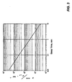
- the timing error ⁇ of the slow clock may be expressed as: ⁇ ⁇ 0.35 ⁇ ⁇ ⁇ t 2 ⁇ chips in the unit of chips. Equations (8) and (9) are both plotted in FIG. 1 to show timing error both in units of ⁇ sec as well as chips. As may be seen in FIG. 1 , the error rises as the duration of a sleep mode increases, with an increasing rate of change. It is noted that since the higher order terms are ignored, Equations (8) and (9) no longer serve as an upper bound.
- a synchronizer tracking circuit within a mobile transceiver can tolerate timing errors up to ⁇ 128 chips, if the sleep clock calibration error is ignored before the mobile goes to sleep, the short sleep time between received frames (less than 1 ⁇ 4 second) is not a problem as long as the channel is well behaved during that period. It is safe for the mobile to go to sleep for any time less than 10 seconds (the flat zone), taking into consideration channel variation and sleep clock tracking error (discussed in the next section). For sleep times of more than 15 sec, re-acquisition of a TDM Pilot II or even TDM Pilot I, in the case of CDMA, is necessary since the sleep clock variance rises quickly in that region.
- TDM Pilot II For sleep times from 20-35 sec, re-acquisition of TDM Pilot II is necessary since TDM Pilot II allows ⁇ 512 chips of timing errors. For sleep times of more than 35 sec, acquiring TDM Pilot I is necessary. Unlike the initial acquisition of TDM Pilot I at power up, we have a rough position of TDM Pilot I. Re-acquiring TDM Pilot I is, therefore, not as costly as is in the initial acquisition.
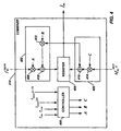
- FIG. 2 illustrates a block diagram of an exemplary device, such as a mobile transceiver, employing sleep clock frequency estimator according to the present disclosure. Since errors in estimating the sleep clock frequency prior to a transceiver device being put to sleep can affect the length of time the device can sleep before the next wakeup time, a higher degree of accuracy of the estimate is beneficial.
- the exemplary device illustrated in FIG. 2 serves to reduce the estimation error.
- a transceiver 200 includes both a fast clock 202 and a slow or sleep clock 204.
- a sleep clock frequency estimator 206 receives a fast clock signal 208 and a sleep clock signal 210 from clocks 202 and 204, respectively.
- the fast and sleep clock signals 208, 210 are sent to a fast clock based sleep clock frequency estimator (TSCFE) 212, which determines an estimate of the sleep clock frequency ( f SC TSCFE ) based on the fast clock implemented with a oscillator such as a TCXO.
- the sleep cock frequency estimator 212 may be configured as described in co-pending U.S. Patent Application entitled "APPARATUS AND METHODS FOR ESTIMATING A SLEEP CLOCK FREQUENCY" referenced above.
- the TCXO sleep clock frequency estimator 212 outputs the fast clock derived estimate of the sleep clock frequency ( f SC TSCFE ) 214 to a combiner 218, which will be discussed further below in connection with FIG. 4 .
- FIG. 2 illustrates that the sleep clock frequency estimator 206 also includes a synchronizer sleep clock frequency estimator (SSCFE) 216.
- the synchronizer sleep clock frequency estimator 216 uses the first arriving path (FAP) as a reference, in the case of CDMA, or the start of a FFT/demodulation window as a reference in the case of OFDM, for example.
- FAP first arriving path
- An estimation of the FAP determined by a synchronizer 219, which may be separate as shown or a part of a processor 220.
- the synchronizer 219 provides the estimation of the FAP to the SSCFE 216 either directly, or via the processor 220 as illustrated in FIG. 2 .
- ⁇ T a measured difference ⁇ T between the actual FAP upon wakeup and the expected FAP based on f ⁇ SC may be determined.
- the FAP drift to correct the sleep clock frequency error is subject to four potential error sources.
- the first two sources of error are the movement or jitter of the FAP, which introduces error, and the estimation of the FAP position. Both result in false corrections to the sleep clock frequency estimate.
- the second error source is negligible for a CDMA transceiver since the CDMA searcher/delay lock loop (DLL) can provide timing accuracy as high as a fractional PN chip. Nonetheless, for other types of transceivers, such as OFDM transceivers, this second source of error is still significant.
- the SSCFE 216 is not updated during the awake period and hence may become obsolete for long awake period. Accordingly, the SSCFE 216, is not suitable for providing estimates when there is a long sleep time.
- the degree of error of the SSCFE 216 may be quantified.
- the SSCFE 216 is configured to receive the ⁇ T and the sleep time T sleep from the processor 220 as indicated by communication line 222. Additionally, SSCFE 216 receives the previous sleep clock frequency estimate f ⁇ SC and the sleep clock frequency estimate ⁇ SC , as indicated by lines 224 and 226, respectively. The SSCFE uses these input values to determine the estimate of the change in the slow clock frequency using equation (10) above. The SSCFE 216 outputs the value of ⁇ ⁇ f SC SSCFE 228 to the combiner 218.
- the combiner 218 is configured to selectively utilize the input values ⁇ ⁇ f SC SSCFE and f SC TSCFE (214, 228) to determine a sleep clock frequency estimate. As will be explained below in connection with FIG. 4 , the combiner 218 utilizes weighting coefficients to selectively assign a reliability rating to the estimates ⁇ ⁇ f SC SSCFE and f SC TSCFE and combine the values such that those values with higher reliability are given greater weight or "credence.”
- the output of the combiner is the estimated sleep clock frequency f ⁇ SC 230, which is sent to the processor 220.
- the processor 220 utilizes the estimated sleep clock frequency 230 to set the maximum sleep time and provide the estimate of the sleep clock frequency prior to directing the transceiver 200 entering into a sleep mode.
- CDMA transceivers typically utilize a fixed sleep and awake pattern in a slotted mode (i.e ., 1.28 • 2 SCI sec sleep and 4 msec awake).
- the SSCFE 218 would have superior estimation performance over the sleep clock frequency estimator 212 for this type of fixed pattern.
- the sleep-awake pattern is flexible. Accordingly, in these types of systems neither the SSCFE 218 or sleep clock frequency estimator 212 would yield superior performance over the other with such flexible patterns. Accordingly, in such types of systems, a combined use of the estimates of the SSCFE 218 and the sleep clock frequency estimator 212 is beneficial.
- the slow clock frequency estimator 206 is configured such that it can work on TSCFE alone without the help from SSCFE.
- An implementation of an adaptive combiner, such as adaptive combiner 218, within a sleep clock frequency estimator is illustrated in FIG. 4 .
- the adaptive combiner 218 receives the estimates of the slow clock frequency ( f SC TSCFE ) and the change in the slow clock frequency ( ⁇ ⁇ f SC SSCFE ).
- a first operational block 400 within the combiner 218 receives the estimate of the slow clock frequency f SC TSCFE for further processing of f SC TSCFE with weighting coefficients A and B .
- a second operational block 402 receives the change in the slow clock frequency ⁇ ⁇ f SC SSCFE for further processing with weighting coefficient C .
- Blocks 400 and 402 send processed outputs, which are values of f ⁇ SC to a register 404 for storage.
- Register 404 is configured as a storage register for storing a current value of f ⁇ SC , but may be implemented with any suitable storage device. Additionally, although register 404 is illustrated as residing within the combiner 218, this storage device may be located as a discrete unit or could also be implemented in the processor 220 or a system memory device 232 shown in FIG. 2 .
- Combiner 218 also includes a controller 406, such as a microcontroller or microprocessor that is used to calculate the weighting coefficients A , B and C .
- the controller 406 receives various inputs from processor 220, for example, for use in determining the weighting coefficients. These inputs include the current wakeup duration ( T wake ) of the wireless device 200, the previous sleep time duration prior to wakeup ( T sleep ), the current measurement time of the TCXO sleep clock frequency estimator 212 ( T measure ( n )), and the previous measurement time of the TCXO sleep clock frequency estimator 212 ( T measure ( n- 1)).
- controller 406 for determining the weighting coefficients include variance of the sleep clock ⁇ SC 2 , variance of the sleep clock frequency estimate ⁇ f ⁇ SC 2 , variance of the synchronizer sleep clock frequency estimate ⁇ SSCFE 2 , variance of the synchronizer timing tracking ⁇ ⁇ ⁇ T 2 , and variance of the TCXO sleep clock frequency estimate ⁇ TSCFE 2 n for a current measurement time n .
- the weighting coefficients A , B and C are selectively or adaptively adjusted by combiner 218 "on the fly” by utilizing the awake time ( T awake ) and sleep time ( T sleep ) in the calculations of the weighting coefficients.
- Coefficients A and B relate to the TCXO sleep clock frequency estimate f SC TSCFE , as do the variables in equations (12) and (13) above.
- Coefficient C relates to the estimate of the change in the slow clock frequency ⁇ ⁇ f SC SSCFE and the variables in equation (14) relate to the variance of the synchronizer slow clock frequency estimator 216 and the synchronizer 219.
- controller 406 is shown as residing within the combiner 218, this device could also be implemented as a discrete unit. Furthermore, the system processor 220 could alternatively perform the functions carried out by controller 406.
- the first operational block 400 includes various multipliers and an adder that are used to determine the frequency estimate output by the block 400 to the register 404.
- the block includes a first multiplier 408 that multiplies the TCXO sleep clock frequency estimate f SC TSCFE by the coefficient A .
- the product of this multiplication is sent to an adder 410.
- Block 400 also includes a second multiplier 412 that multiplies the value of the estimated sleep clock frequency f ⁇ SC stored in register 404 by coefficient B .
- Multiplier 412 outputs the product to adder 410, where the products of multipliers 408 and 412 are summed together. It is noted that the sum of coefficients A and B will always be unity (1).
- coefficient A determines or "weights" the percentage of how much the TXCO sleep clock frequency estimate f SC TSCFE is given relevance
- coefficient B likewise determines the percentage degree of relevance the previously determined sleep clock frequency estimate f ⁇ SC is given. Accordingly, the summed output of adder 410 is a newly determined sleep clock frequency estimate f ⁇ SC that is stored in register 404.
- Block 402 also calculates an estimate of the sleep clock frequency f ⁇ SC and writes the value to register 404.
- the coefficient C provides a multiplier establishing a quantitative degree of reliability of the estimated change in the slow clock frequency ( ⁇ ⁇ f SC SSCFE ) . After the value ⁇ ⁇ f SC SSCFE is multiplied by coefficient C , this establishes a modified or weighted value of the change in the slow clock frequency that is subsequently added to the previous value of f ⁇ SC to determine a new estimated value f ⁇ SC written to register 404.
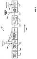
- FIG. 5 shows a timeline 500 of the operation of a mobile wireless device, such as transceiver 200, utilizing the apparatus of FIGs. 2 and 4 .
- Timeline 500 illustrates the operation of a device from just after wakeup from a sleep mode to the entry of another sleep period.
- the fast clock e.g., TCXO 202
- a wakeup clock expires (block 506)
- the fast clock takes over for system timing, as indicated by arrow 508.
- various operations pertinent to the device operation commence as shown in blocks 510.
- the synchronizer 219 then starts timing as indicated by block 512.
- the synchronizer slow clock frequency estimator 216 can update the estimate of ⁇ ⁇ f SC SSCFE , which, in turn, allows the second operational block 402 to determine and store a new value for f ⁇ SC in register 404.
- the processor 220 will decide to put the device 200 into a sleep mode, as indicated by arrow 516.
- the slow clock frequency estimate f SC TSCFE of the TCXO slow clock frequency estimator (TSCFE) 212 will determined by the processor 220 (or similar logic in the estimator 212 itself) and delivered to block 400 in the combiner 218, which occurs at block 518 in FIG. 5 .
- a new estimate for f ⁇ SC is then determined by block 400 and written to register 404, thus overwriting the previous new estimate written by block 402. Both estimates of f ⁇ SC from each of block 400 and 402 are valuable, as block 400, for example, uses the current estimate of f ⁇ SC stored in register 404, for determining the new estimate.
- this value can be read out the register by processor 220, for example, in setting the maximum sleep time (e.g., setting the sleep clock timer at block 520) just prior to entering sleep mode as indicated by arrow 522.
- FIG. 6 illustrates a flow diagram of a method 600 for determining a slow clock frequency estimate f ⁇ SC in accordance with the present disclosure.
- the method 600 is initialized at block 602 and corresponds to a wakeup of device 200, for example.
- Flow proceeds to block 604, where an estimated change in sleep clock frequency is determined.
- SSCFE 216 may perform this part of the process, for example.
- a weighted estimated change in sleep clock frequency is determined using a calculated coefficient (e.g., coefficient C ) to weight the value of the sleep clock frequency change 606.
- This part of the process is implemented, for example, by the second operational block 402 within the combiner 218 and, more particularly with multiplier 414.
- the process of block 608 may be effected with adder 416, for example.
- the new estimate of the sleep clock frequency ( f ⁇ SC ) is calculated, it is stored in a memory (e.g., register 404) as shown by block 610.
- an estimate of sleep clock frequency is determined using the fast clock as indicated in block 612.
- the T C XO sleep clock frequency estimator 212 may perform this part of the process, for example. Additionally, it is noted the estimator 212 may be operational simultaneous with the SSCFE 216 used to determine the change in the slow clock frequency, although the information determined by the estimator 212 will not be used until after the information from the SSCFE 216 is utilized in determining the new estimate of sleep clock frequency.
- flow proceeds to block 614 for determination of a weighted estimated sleep clock frequency using at least one calculated coefficient (e.g., at least one of coefficients A and B ) to weight the value of the estimated sleep clock frequency.
- the part of the process may be effected with first operational block 400 and, more particularly, with multipliers 408 and 412.
- a further new estimate for sleep clock frequency is determined at block 616 using the weighted estimated change in sleep clock frequency determined at block 614 and the previously stored new estimate for sleep clock frequency.
- Multiplier 412 i.e., multiplying the stored new estimate with a coefficient
- the adder 410 perform this determination.
- this further new estimate is determined, it is stored in the memory device (e.g., register 404), thus overwriting the previously stored new estimate as indicated in block 618.
- Processor 220 may then use this further new estimate to set the sleep time for the transceiver 200, for example.
- FIG. 7 illustrates another example of a device employing a sleep clock frequency estimator.
- the device 700 may be a wireless device such as a transceiver. Accordingly, the device 700 includes an antenna 702 for receiving and transmitting wireless communication signals. Within the device 700, are a fast clock and a sleep clock (not shown) for keeping system time during awake and sleep periods, respectively. The device then includes means for effecting frequency estimation of the sleep clock. Included are means for estimating a change in sleep clock frequency 704.
- Means 704 is equivalent to, as an example, the SSCFE 216 illustrated in FIG. 2 for determining an estimate of ⁇ ⁇ f SC SSCFE , as well as synchronizer 219 and processor 220, which determine variable used in determining the estimate of ⁇ ⁇ f SC SSCFE .
- means 706 for determining a weighted estimated change in sleep clock frequency using a calculated coefficient to weight the value of the sleep clock frequency change.
- Means 706 is similar to the second operational block 402 of the combiner 218 shown in FIG. 4 .
- means 706 can be effected with the multiplier 414 and controller 406, as an example.
- means 706 outputs this result to means 708 for determining a new estimate for sleep clock frequency (e.g., f ⁇ SC ) using weighted estimated change in sleep clock frequency and a previous estimated sleep clock frequency 708. As may be seen in FIG.
- a previous estimated sleep clock frequency 709 is input (or fed back) to means 708 for determination of the new estimate.
- Means 708 may be implemented, for example, by adder 416 in second operational block 402.
- Means 708 then stores or writes the new estimated sleep clock frequency f ⁇ SC in a means 710 for storing the estimated sleep clock frequency.
- Means 710 may be implemented by a memory, a register (e.g., register 404) or any other suitable device capable of storing data.
- the transceiver 700 also includes means 712 for estimating the sleep clock frequency using a fast clock.
- Means 712 can be effected with the TSCFE 212 discussed in FIG. 2 , or any other similar device for measuring a clock using another clock, and a processor or hardware to calculate the frequency estimate (e.g., processor 220).
- the result is input to means 714 for determining a weighted estimated sleep clock frequency using at least one calculated coefficient to weight the value of the estimated sleep clock frequency.
- Means 714 could be implemented, for example, with multipliers 408 and 412 in block 400 and controller 406 shown in FIG. 4 , but is not necessarily limited to only such an implementation.
- the resultant weighted sleep clock frequency estimate output from means 714 is input to means 716 for determining a further new estimate for sleep clock frequency using weighted estimated change in sleep clock frequency and the previously stored new estimate for sleep clock frequency stored by means 708 is the storage means 710.
- a feedback of the previously stored new estimate 718 is input to means 716 for making the determination of the further new estimate.
- Means 716 may be implemented with multiplier 412 as it applies a coefficient to the new estimate of sleep clock frequency and adder 410, which receives the products of multiplier 408 and 412.
- the resultant further new estimate of the sleep clock frequency is written in the means for storing 710, thereby overwriting the new estimate determined by means 708.
- the value of the further new estimate f ⁇ SC stored in storage means 710 may be accessed or output 720 for use by other means (not shown) in the transceiver 700 for determining a sleep time for the device 700.
- the presently disclosed estimators above require no computation and can thus be implemented solely in hardware (except for the adders, which can be implemented in the microprocessor).
- the presently disclosed sleep clock frequency estimator improves estimation accuracy by providing the microprocessor with the most recent estimate with longest possible and appropriate measurement period whenever the microprocessor requires.
- the disclosed constantly functioning estimators eliminate extra ⁇ 1 errors that can arise due to constant interruption of the fast clock counting process.
- the disclosed estimators do not require intervention from the microprocessor (i.e., the microprocessor does not need to instruct the estimator when to start and when to stop counting).
- a software module may reside in RAM memory, flash memory, ROM memory, EPROM memory, EEPROM memory, registers, a hard disk, a removable disk, a CD-ROM, or any other form of storage medium known in the art.
- An exemplary storage medium is coupled to the processor, such that the processor can read information from, and write information to the storage medium.
- the storage medium may be integral to the processor.
- the processor and the storage medium may reside in an ASIC or similar processing circuit.
- the ASIC may reside in a user terminal or other wireless device.
- the processor and the storage medium may reside as discrete components in a user terminal or wireless device. Additionally the other components, such as those within the device 200 in FIG. 2 , for example, could also reside with the ASIC or processing circuit, or reside as discrete components in the device 200.
Abstract
Description
- The present Application for Patent claims priority to Provisional Application No.
60/660,833 - The present disclosure relates to methods and apparatus for estimating a sleep clock frequency and, more particularly, estimating a sleep clock frequency using a combiner to selectively determine an estimate of the sleep clock frequency.
- Mobile wireless devices, such as mobile phones, typically employ clock that provides very accurate timing for various functions within the device including keeping the system time. These clocks many times are embodied using temperature controlled crystal oscillators (TCXOs). TCXOs, however, use a relatively large amount of power, drawing approximately 1.5 mA of current
- In order to improve the battery life of a mobile device, it is known to place most current consuming units within the device into a power saving mode and maintain the system time using low-power sleep circuits. Because of the high current draw of TCXOs, it is not energy efficient to use such devices to maintain system time for sleep circuits. Accordingly, it is known to maintain system timing during sleep or power saving modes using by using a sleep controller having a much lower power usage (e.g., a clock with a current draw of 200 pA) and a lower frequency (e.g., 30-60 kHz) than TCXO devices, which operate a higher frequency (e.g., 44-66 MHz). This is typically accomplished with a cost effective crystal oscillator clock at the expense of some accuracy in time keeping because the clock frequency tends to fluctuate. This clock is otherwise known as the "sleep clock" or "slow clock." Thus, when the mobile device is asleep, the TCXO (or "fast clock") is off. The sleep clock is used as a timer to wake up the system. Upon wake up, once the fast clock becomes stable after waking up, system timing is once again handed over to the fast clock.
- It is noted that when a mobile device wakes up from a sleep mode, it is important to have an accurate system time as kept by the sleep clock. Since the sleep clock is used for system timing during sleep modes, the accuracy of the clock timing will directly affect the system time when the mobile transceiver wakes up prior to re-acquisition of timing based on information received from the wireless network, such as a CDMA based network. A good estimate of slow clock frequency is therefore desirable. Known timing estimation utilized by mobile devices, however, is typically used only for initial calibration and the slow clock time tracking is solely dependent on Pseudo Noise (PN) code timing. In certain wireless systems not employing PN timing . (e.g., Orthogonal Frequency Division Multiplexing (OFDM)), however, this timing in not available. Thus, in such systems the accuracy of the sleep clock timing is even more important. In the case of OFDM, in particular, such systems are more susceptible to timing errors such as synchronization timing made worse by intersymbol interference.
- It is further noted that issues exist related to determining an accurate estimate of the slow clock. First, the resolution of sleep clocks is low and the sleep clock is not synchronized with the fast clock This issue can be resolved, however, by using the fast clock (derived from TCXO) to count the fractional part of the sleep clock as detailed, for example, in the co-pending
U.S. Patent Application no. 11/271,445 entitled "APPARATUS AND METHODS FOR ESTIMATING A SLEEP CLOCK FREQUENCY". - Furthermore, because the slow clock is a low accuracy, free running crystal without temperature compensation, the system time may drift during sleep. Accordingly, it is desirable to account for this drift and thus determine a maximum sleep time that may be set for the mobile device so that there is no need for re-acquisition of system time on wakeup. Finally, because the sleep clock is used as a timer during sleep, it is necessary to have a good estimate of the sleep clock frequency before going to sleep.
- It is possible using the methodologies above to achieve an accurate estimate of the sleep clock frequency for specific situations. However, in the case of OFDM, for example, determining system timing using CDMA PN codes may not be available for determining timing. Moreover, determining an estimate of the sleep clock using the fast clock may yield a very accurate estimate of the sleep clock frequency, but does not account for the change or error due to drift of the sleep clock. Furthermore, if the sleep clock frequency is accurately determined and the error or drift of the sleep frequency is determined, how to combine this information to yield an accurate result has not been contemplated in the known art.
-
WO 02/47281 A1 - This problem is solved by the apparatuses, method and computer readable medium according to
claims - Apparatus and methods are presently disclosed determining accurate sleep clock timing. In one example, an apparatus is disclosed for determining a frequency estimate of a sleep clock. In particular, the apparatus includes a sleep clock frequency estimator configured to output a fast clock derived sleep clock frequency estimate; a sleep clock change frequency estimator configured to output an estimate of a change in frequency of the sleep clock; and a combiner configured to weight at least one of the fast clock derived sleep clock frequency estimate to obtain a weighted sleep clock frequency estimate and the estimate of the change in frequency of the sleep clock to obtain a weighted estimate of the change in frequency of the sleep clock, and to determine at least one new estimate of the sleep clock frequency using at least one of the weighted sleep clock frequency estimate and the weighted estimate of the change in frequency of the sleep clock.
- According to another disclosed example, a processing circuit for estimating a sleep clock frequency for use in a wireless transceiver system includes a sleep clock frequency estimator configured to output a fast clock derived sleep clock frequency estimate; a sleep clock change frequency estimator configured to output an estimate of a change in frequency of the sleep clock; a combiner configured to selectively weight at least one of the fast clock derived sleep clock frequency estimate to obtain a weighted sleep clock frequency estimate and the estimate of the change in frequency of the sleep clock to obtain a weighted estimate of the change in frequency of the sleep clock, and to determine at least one new estimate of the sleep clock frequency using at least one of the weighted sleep clock frequency estimate and the weighted estimate of the change in frequency of the sleep clock; a memory device configured to store the at least one new estimate of the slow clock frequency weighting estimate; and a processor configured to read the at least one new estimate from the memory device and calculate a system sleep time based on the at least one new estimate prior to entering the system into a sleep mode.
- In still another example, a wireless device is disclosed for use in a mobile communications network. The device includes a sleep clock frequency estimator configured to output a fast clock derived sleep clock frequency estimate; a sleep clock change frequency estimator configured to output an estimate of a change in frequency of the sleep clock; a combiner configured to selectively weight at least one of the fast clock derived sleep clock frequency estimate to obtain a weighted sleep clock frequency estimate and the estimate of the change in frequency of the sleep clock to obtain a weighted estimate of the change in frequency of the sleep clock, and to determine at least one new estimate of the sleep clock frequency using at least one of the weighted sleep clock frequency estimate and the weighted estimate of the change in frequency of the sleep clock; a memory device configured to store the at least one new estimate of the slow clock frequency weighting estimate; and a processor configured to read the at least one new estimate from the memory device and calculate a sleep time of the wireless device based on the at least one new estimate prior to entering the system into a sleep mode.
- In yet another example, a method for estimating the frequency of a sleep clock is disclosed. The method includes estimating a change in sleep clock frequency; determining a weighted estimated change in sleep clock frequency using a calculated coefficient to weight the value of the sleep clock frequency change; determining a new estimate for sleep clock frequency using the weighted estimated change in sleep clock frequency and a previous estimated sleep clock frequency and storing the new estimate in a memory device; estimating a sleep clock frequency using a fast clock; determining a weighted estimated sleep clock frequency using at least another calculated coefficient to weight the value of the estimated sleep clock frequency; determining a further new estimate for sleep clock frequency using weighted estimated change in sleep clock frequency and the previously stored new estimate for sleep clock frequency; and storing the further new estimate in memory such that the further new estimate replaces the new estimate.
- According to still another example, a computer readable medium is disclosed having instructions stored thereon, the stored instructions, when executed by a processor, causing the processor to perform a method of estimating the frequency of a sleep clock. The method performed includes estimating a change in sleep clock frequency; determining a weighted estimated change in sleep clock frequency using a calculated coefficient to weight the value of the sleep clock frequency change; determining a new estimate for sleep clock frequency using the weighted estimated change in sleep clock frequency and a previous estimated sleep clock frequency and storing the new estimate in a memory device; estimating a sleep clock frequency using a fast clock; determining a weighted estimated sleep clock frequency using at least another calculated coefficient to weight the value of the estimated sleep clock frequency; determining a further new estimate for sleep clock frequency using weighted estimated change in sleep clock frequency and the previously stored new estimate for sleep clock frequency; and storing the further new estimate in memory such that the further new estimate replaces the new estimate.
- In yet another example, an apparatus is disclosed for estimating the frequency of a sleep clock. The apparatus includes means for estimating a change in the sleep clock frequency; means for determining a weighted estimated change in sleep clock frequency using a calculated coefficient to weight the value of the sleep clock frequency change; means for determining a new estimate for sleep clock frequency using the weighted estimated change in sleep clock frequency and a previous estimated sleep clock frequency; means for storing that stores the new estimate; means for estimating a sleep clock frequency using a fast clock; means for determining a weighted estimated sleep clock frequency using at least one calculated coefficient to weight the value of the estimated sleep clock frequency; and means for determining a further new estimate for sleep clock frequency using weighted estimated change in sleep clock frequency and the previously stored new estimate for sleep clock frequency. It is further noted that in this example the means for storing stores the further new estimate such that the further new estimate replaces the new estimate.
-
FIG. 1 is a plot of the error in sleep timing as a function of the sleep time duration. -
FIG. 2 is a block diagram of an exemplary device, such as a mobile transceiver, employing a sleep clock frequency estimator according to the present disclosure. -
FIG. 3 is a plot of error variance of a synchronizer sleep clock estimator with respect to sleep time. -
FIG. 4 is a block diagram of an exemplary sleep clock frequency estimator according to the present disclosure. -
FIG. 5 is an exemplary time line illustrating a sequence of events occurring in a device employing the sleep clock frequency estimator ofFIG. 4 . -
FIG. 6 is a flow diagram of an example method for estimating sleep clock frequency in a wireless device. -
FIG. 7 is another example of a device employing a sleep clock frequency estimator. - In order to determine an accurate estimate of slow clock frequency, apparatus and methods are presently disclosed that combine a slow clock frequency estimate with an estimate of the slow clock frequency change. The combination of these estimates if performed selectively where the estimates are multiplied by coefficients based on the reliability of the estimate source. By taking into account both estimates, as well as weighting those estimates based on reliability, the
- In order to ensure an accurate estimate of the sleep clock frequency, the accuracy is first modeled. The slow/sleep clock frequency accuracy as a function of temperature can be modeled as:

where T is the temperature in degrees Celsius and the base frequency of a sleep clock crystal at 25°C is 32kHz in this example. The type of crystal will, of course, affect the values of the coefficients in equation (1) and, thus, this is only exemplary. The frequency rate of change rate with respect to temperature is thus given as:
- Assuming that the temperature change over time for the sleep clock is defined by

the frequency change over time is then given as:
Assuming the operating temperature range is -20°C to 70°C, the maximum frequency change rate would be
- If the a mobile transceiver decides to go to sleep from a time t to t + Δt, the timing error ε due to the time varying characteristics of the sleep clock is then determined by the following:

If the high order terms (i.e.,

Substituting equation (5) into (7) yields a value of the error e expressed as:
Expressed another way, the timing error ε of the slow clock may be expressed as:
in the unit of chips. Equations (8) and (9) are both plotted inFIG. 1 to show timing error both in units of µsec as well as chips. As may be seen inFIG. 1 , the error rises as the duration of a sleep mode increases, with an increasing rate of change. It is noted that since the higher order terms are ignored, Equations (8) and (9) no longer serve as an upper bound. - It is noted that the above example is used for the purpose of explaining concepts underlying the presently disclosed apparatus and methods. The parameters and coefficients used are thus based on typical slow clock crystal parameters, but are not meant to limit the disclosure to such parameters, coefficients or types of slow clock crystals.
- Because a synchronizer tracking circuit within a mobile transceiver can tolerate timing errors up to ±128 chips, if the sleep clock calibration error is ignored before the mobile goes to sleep, the short sleep time between received frames (less than ¼ second) is not a problem as long as the channel is well behaved during that period. It is safe for the mobile to go to sleep for any time less than 10 seconds (the flat zone), taking into consideration channel variation and sleep clock tracking error (discussed in the next section). For sleep times of more than 15 sec, re-acquisition of a TDM Pilot II or even TDM Pilot I, in the case of CDMA, is necessary since the sleep clock variance rises quickly in that region. For sleep times from 20-35 sec, re-acquisition of TDM Pilot II is necessary since TDM Pilot II allows ±512 chips of timing errors. For sleep times of more than 35 sec, acquiring TDM Pilot I is necessary. Unlike the initial acquisition of TDM Pilot I at power up, we have a rough position of TDM Pilot I. Re-acquiring TDM Pilot I is, therefore, not as costly as is in the initial acquisition.
-
FIG. 2 illustrates a block diagram of an exemplary device, such as a mobile transceiver, employing sleep clock frequency estimator according to the present disclosure. Since errors in estimating the sleep clock frequency prior to a transceiver device being put to sleep can affect the length of time the device can sleep before the next wakeup time, a higher degree of accuracy of the estimate is beneficial. The exemplary device illustrated inFIG. 2 serves to reduce the estimation error. As shown, atransceiver 200 includes both afast clock 202 and a slow orsleep clock 204. A sleepclock frequency estimator 206 receives afast clock signal 208 and a sleep clock signal 210 fromclocks 
cock frequency estimator 212 may be configured as described in co-pending U.S. Patent Application entitled "APPARATUS AND METHODS FOR ESTIMATING A SLEEP CLOCK FREQUENCY" referenced above. The TCXO sleepclock frequency estimator 212 outputs the fast clock derived estimate of the sleep clock frequency (
combiner 218, which will be discussed further below in connection withFIG. 4 . -
FIG. 2 illustrates that the sleepclock frequency estimator 206 also includes a synchronizer sleep clock frequency estimator (SSCFE) 216. The synchronizer sleepclock frequency estimator 216 uses the first arriving path (FAP) as a reference, in the case of CDMA, or the start of a FFT/demodulation window as a reference in the case of OFDM, for example. An estimation of the FAP determined by asynchronizer 219, which may be separate as shown or a part of aprocessor 220. Thesynchronizer 219 provides the estimation of the FAP to theSSCFE 216 either directly, or via theprocessor 220 as illustrated inFIG. 2 . - It is noted here that an error in sleep clock frequency as a result of frequency estimation error before the
device 200 is put to sleep and frequency drift of thesleep clock 204 during sleep results in an FAP drift on wakeup. This drift can be utilized, however, to correct the sleep clock frequency errors. In particular, theSSCFE 216 utilizes this information to determine an estimate of the frequency change (
clock frequency estimator 206 before going to sleep (i.e.,
- Specifically concerning using the FAP drift to determine

transceiver 200, the estimate

It is noted that the value of ΔT will be negative if the expected FAP lags behind the actual FAP upon wakeup. - Notwithstanding the above formulation, use of the FAP drift to correct the sleep clock frequency error is subject to four potential error sources. The first two sources of error are the movement or jitter of the FAP, which introduces error, and the estimation of the FAP position. Both result in false corrections to the sleep clock frequency estimate. It is further noted, however, that the second error source is negligible for a CDMA transceiver since the CDMA searcher/delay lock loop (DLL) can provide timing accuracy as high as a fractional PN chip. Nonetheless, for other types of transceivers, such as OFDM transceivers, this second source of error is still significant. Third, the estimation of represents the average frequency of the sleep clock during sleep (i.e.,

SSCFE 216 is not updated during the awake period and hence may become obsolete for long awake period. Accordingly, theSSCFE 216, is not suitable for providing estimates when there is a long sleep time. - The degree of error of the
SSCFE 216 may be quantified. Specifically, the estimation error variance εSSCFE due to synchronizer timing and FAP jitter (and ignoring sleep clock drift, for simplicity) may be given by the following relationship:
- where εΔT is the synchronizer timing estimation error as well as FAP jitter variance.
FIG. 3 is a plot of Equation (11) over a 10 second sleep time and a sleep clock frequency of 32 kHz. From this plot, it may be seen thatSSCFE 216 is, in terms of estimation variance, not accurate for very short sleep times either. As another quantitative example in a CDMA transceiver, if the value of εΔT ≈356 n sec assuming no FAP jitter and the sleep time duration is 5 seconds, the ratio ε SSCFE /fSC = 0.07 ppm. If the error of the SSCFE is too unreliable, it is noted that the sleepclock frequency estimator 206 is configured such that it will work without the frequency estimate from theSSCFE 216, as will be explained later. - Referring again to
FIG. 2 , theSSCFE 216 is configured to receive the ΔT and the sleep time Tsleep from theprocessor 220 as indicated bycommunication line 222. Additionally,SSCFE 216 receives the previous sleep clock frequency estimate f̂SC and the sleep clock frequency estimate ƒSC, as indicated bylines SSCFE 216 outputs the value of
combiner 218. - The
combiner 218 is configured to selectively utilize the input values

FIG. 4 , thecombiner 218 utilizes weighting coefficients to selectively assign a reliability rating to the estimates

clock frequency f̂ SC 230, which is sent to theprocessor 220. Theprocessor 220, in turn, utilizes the estimatedsleep clock frequency 230 to set the maximum sleep time and provide the estimate of the sleep clock frequency prior to directing thetransceiver 200 entering into a sleep mode. - It is noted that CDMA transceivers typically utilize a fixed sleep and awake pattern in a slotted mode (i.e., 1.28 • 2SCI sec sleep and 4 msec awake). For this type of transceiver, the
SSCFE 218 would have superior estimation performance over the sleepclock frequency estimator 212 for this type of fixed pattern. In other types of transceivers such as OFDM transceiver, however, the sleep-awake pattern is flexible. Accordingly, in these types of systems neither theSSCFE 218 or sleepclock frequency estimator 212 would yield superior performance over the other with such flexible patterns. Accordingly, in such types of systems, a combined use of the estimates of theSSCFE 218 and the sleepclock frequency estimator 212 is beneficial. This benefit is, in part, due to the fact that the two estimates are from independent sources, (i.e., the estimation errors are independent) and consequently provide an improved and robust estimate for variable sleep-awake patterns over using a single estimate. Notwithstanding, it is again noted that in the presently disclosed apparatus and methods, the slowclock frequency estimator 206 is configured such that it can work on TSCFE alone without the help from SSCFE. An implementation of an adaptive combiner, such asadaptive combiner 218, within a sleep clock frequency estimator is illustrated inFIG. 4 . - As illustrated in
FIG. 4 , theadaptive combiner 218 receives the estimates of the slow clock frequency (

operational block 400 within thecombiner 218 receives the estimate of the slow clock frequency

operational block 402 receives the change in the slow clock frequency
coefficient C. Blocks register 404 for storage.Register 404 is configured as a storage register for storing a current value of f̂SC, but may be implemented with any suitable storage device. Additionally, althoughregister 404 is illustrated as residing within thecombiner 218, this storage device may be located as a discrete unit or could also be implemented in theprocessor 220 or asystem memory device 232 shown inFIG. 2 . -
Combiner 218 also includes acontroller 406, such as a microcontroller or microprocessor that is used to calculate the weighting coefficients A, B and C. Thecontroller 406 receives various inputs fromprocessor 220, for example, for use in determining the weighting coefficients. These inputs include the current wakeup duration (Twake ) of thewireless device 200, the previous sleep time duration prior to wakeup (Tsleep ), the current measurement time of the TCXO sleep clock frequency estimator 212 (Tmeasure (n)), and the previous measurement time of the TCXO sleep clock frequency estimator 212 (Tmeasure (n-1)). - Additional variables used by
controller 406 for determining the weighting coefficients include variance of the sleepclock 

estimate 


SSCFE 216 andTSCFE 212 estimates are dependent on the sleep time duration (Tsleep ) and awake time duration (Tawake ), respectively, and the sleep time and awake time vary, the weighting coefficients A, B and C are selectively or adaptively adjusted bycombiner 218 "on the fly" by utilizing the awake time (Tawake ) and sleep time (Tsleep ) in the calculations of the weighting coefficients. As an example, the weighting coefficients may be calculated using the following equations:
and
and
where β is a predetermined optimization constant. Coefficients A and B relate to the TCXO sleep clock frequency estimate

clock frequency estimator 216 and thesynchronizer 219. One of ordinary skill in the art will appreciate, however, that equations (12), (13), and (14) are only exemplary, and numerous other formulations that account for and weight the reliability of each sleep clock frequency estimate may be contemplated. It is noted that, in this particular implementation, the units of time used in the coefficients are measured in slow clock cycles, but other units could be used instead. Of further note, for an initial measurement where n = 0, the value of Tmeasure (n - 1) will be equal to zero (i.e., Tmeasure (-1) = 0). - It is noted that although
controller 406 is shown as residing within thecombiner 218, this device could also be implemented as a discrete unit. Furthermore, thesystem processor 220 could alternatively perform the functions carried out bycontroller 406. - From
FIG. 4 it can be seen that the firstoperational block 400 includes various multipliers and an adder that are used to determine the frequency estimate output by theblock 400 to theregister 404. In particular, the block includes afirst multiplier 408 that multiplies the TCXO sleep clock frequency estimate
adder 410. Block 400 also includes asecond multiplier 412 that multiplies the value of the estimated sleep clock frequency f̂SC stored inregister 404 bycoefficient B. Multiplier 412 outputs the product to adder 410, where the products ofmultipliers 
adder 410 is a newly determined sleep clock frequency estimate f̂SC that is stored inregister 404. - Block 402 also calculates an estimate of the sleep clock frequency f̂SC and writes the value to register 404. In particular, the coefficient C provides a multiplier establishing a quantitative degree of reliability of the estimated change in the slow clock frequency (


- It is noted here that the value of f̂SC stored in
register 404 is temporal, and that the value is written from either block 400 or block 402 , but not both. That is, whichever block operates latest, the value of f̂SC from that block overwrites the value of f̂SC presently stored inregister 404. As an illustration of this temporal relationship,FIG. 5 shows atimeline 500 of the operation of a mobile wireless device, such astransceiver 200, utilizing the apparatus ofFIGs. 2 and4 .Timeline 500 illustrates the operation of a device from just after wakeup from a sleep mode to the entry of another sleep period. After a warmup clock expires as shown atblock 502, the fast clock (e.g., TCXO 202) warms up (block 504), and a wakeup clock expires (block 506), the fast clock takes over for system timing, as indicated byarrow 508. After the device is fully awakened, various operations pertinent to the device operation commence as shown inblocks 510. Thesynchronizer 219 then starts timing as indicated byblock 512. Once thesynchronizer 219 has started, the synchronizer slowclock frequency estimator 216 can update the estimate of
operational block 402 to determine and store a new value for f̂SC inregister 404. After a further period of time, theprocessor 220 will decide to put thedevice 200 into a sleep mode, as indicated byarrow 516. At this time the slow clock frequency estimate
estimator 212 itself) and delivered to block 400 in thecombiner 218, which occurs atblock 518 inFIG. 5 . A new estimate for f̂SC is then determined byblock 400 and written to register 404, thus overwriting the previous new estimate written byblock 402. Both estimates of f̂SC from each ofblock block 400, for example, uses the current estimate of f̂SC stored inregister 404, for determining the new estimate. Once the latest or newest estimate of f̂SC is stored inregister 404, this value can be read out the register byprocessor 220, for example, in setting the maximum sleep time (e.g., setting the sleep clock timer at block 520) just prior to entering sleep mode as indicated byarrow 522. -
FIG. 6 illustrates a flow diagram of amethod 600 for determining a slow clock frequency estimate f̂SC in accordance with the present disclosure. Themethod 600 is initialized atblock 602 and corresponds to a wakeup ofdevice 200, for example. Flow proceeds to block 604, where an estimated change in sleep clock frequency is determined.SSCFE 216 may perform this part of the process, for example. Next, a weighted estimated change in sleep clock frequency is determined using a calculated coefficient (e.g., coefficient C) to weight the value of the sleepclock frequency change 606. This part of the process is implemented, for example, by the secondoperational block 402 within thecombiner 218 and, more particularly withmultiplier 414. - Flow then proceeds to block 608, where a new estimate for sleep clock frequency using the weighted estimated change in sleep clock frequency and a previously estimated sleep clock frequency (f̂SC ), which is stored in
register 404, for example. The process ofblock 608 may be effected withadder 416, for example. After the new estimate of the sleep clock frequency (f̂SC ) is calculated, it is stored in a memory (e.g., register 404) as shown byblock 610. - After the new estimate of the sleep clock frequency (f̂SC ) is stored, an estimate of sleep clock frequency is determined using the fast clock as indicated in
block 612. The TCXO sleepclock frequency estimator 212 may perform this part of the process, for example. Additionally, it is noted theestimator 212 may be operational simultaneous with theSSCFE 216 used to determine the change in the slow clock frequency, although the information determined by theestimator 212 will not be used until after the information from theSSCFE 216 is utilized in determining the new estimate of sleep clock frequency. Afterblock 612, flow proceeds to block 614 for determination of a weighted estimated sleep clock frequency using at least one calculated coefficient (e.g., at least one of coefficients A and B) to weight the value of the estimated sleep clock frequency. The part of the process may be effected with firstoperational block 400 and, more particularly, withmultipliers - Next, a further new estimate for sleep clock frequency is determined at
block 616 using the weighted estimated change in sleep clock frequency determined atblock 614 and the previously stored new estimate for sleep clock frequency. Multiplier 412 (i.e., multiplying the stored new estimate with a coefficient) and theadder 410 perform this determination. Once this further new estimate is determined, it is stored in the memory device (e.g., register 404), thus overwriting the previously stored new estimate as indicated inblock 618.Processor 220 may then use this further new estimate to set the sleep time for thetransceiver 200, for example. The process ends attermination block 620, which may be the start of a sleep mode for thetransceiver 200, for example. -
FIG. 7 illustrates another example of a device employing a sleep clock frequency estimator. As illustrated, thedevice 700 may be a wireless device such as a transceiver. Accordingly, thedevice 700 includes anantenna 702 for receiving and transmitting wireless communication signals. Within thedevice 700, are a fast clock and a sleep clock (not shown) for keeping system time during awake and sleep periods, respectively. The device then includes means for effecting frequency estimation of the sleep clock. Included are means for estimating a change insleep clock frequency 704.Means 704 is equivalent to, as an example, theSSCFE 216 illustrated inFIG. 2 for determining an estimate of
synchronizer 219 andprocessor 220, which determine variable used in determining the estimate of
- The output of
means 704 is input to means 706 for determining a weighted estimated change in sleep clock frequency using a calculated coefficient to weight the value of the sleep clock frequency change.Means 706 is similar to the secondoperational block 402 of thecombiner 218 shown inFIG. 4 . In particular, means 706 can be effected with themultiplier 414 andcontroller 406, as an example. Once the weighted estimated change is determined, means 706 outputs this result tomeans 708 for determining a new estimate for sleep clock frequency (e.g., f̂SC ) using weighted estimated change in sleep clock frequency and a previous estimatedsleep clock frequency 708. As may be seen inFIG. 7 , a previous estimatedsleep clock frequency 709 is input (or fed back) to means 708 for determination of the new estimate.Means 708 may be implemented, for example, byadder 416 in secondoperational block 402.Means 708 then stores or writes the new estimated sleep clock frequency f̂SC in ameans 710 for storing the estimated sleep clock frequency.Means 710 may be implemented by a memory, a register (e.g., register 404) or any other suitable device capable of storing data. - The
transceiver 700 also includesmeans 712 for estimating the sleep clock frequency using a fast clock.Means 712 can be effected with theTSCFE 212 discussed inFIG. 2 , or any other similar device for measuring a clock using another clock, and a processor or hardware to calculate the frequency estimate (e.g., processor 220). Once the slow clock frequency is estimate withmeans 712, the result is input to means 714 for determining a weighted estimated sleep clock frequency using at least one calculated coefficient to weight the value of the estimated sleep clock frequency.Means 714 could be implemented, for example, withmultipliers block 400 andcontroller 406 shown inFIG. 4 , but is not necessarily limited to only such an implementation. The resultant weighted sleep clock frequency estimate output from means 714 is input to means 716 for determining a further new estimate for sleep clock frequency using weighted estimated change in sleep clock frequency and the previously stored new estimate for sleep clock frequency stored bymeans 708 is the storage means 710. As may be seen inFIG. 7 , a feedback of the previously storednew estimate 718 is input to means 716 for making the determination of the further new estimate.Means 716 may be implemented withmultiplier 412 as it applies a coefficient to the new estimate of sleep clock frequency andadder 410, which receives the products ofmultiplier means 708. The value of the further new estimate f̂SC stored in storage means 710 may be accessed oroutput 720 for use by other means (not shown) in thetransceiver 700 for determining a sleep time for thedevice 700. - The presently disclosed estimators above require no computation and can thus be implemented solely in hardware (except for the adders, which can be implemented in the microprocessor). Compared to the current design of the TCXO based sleep clock frequency estimator the presently disclosed sleep clock frequency estimator improves estimation accuracy by providing the microprocessor with the most recent estimate with longest possible and appropriate measurement period whenever the microprocessor requires. Additionally the disclosed constantly functioning estimators eliminate
extra ± 1 errors that can arise due to constant interruption of the fast clock counting process. Moreover, the disclosed estimators do not require intervention from the microprocessor (i.e., the microprocessor does not need to instruct the estimator when to start and when to stop counting). - The methods or algorithms described in connection with the examples disclosed herein may be embodied directly in hardware, in a software module executed by a processor, firmware, or in a combination of two or more of these. A software module may reside in RAM memory, flash memory, ROM memory, EPROM memory, EEPROM memory, registers, a hard disk, a removable disk, a CD-ROM, or any other form of storage medium known in the art. An exemplary storage medium is coupled to the processor, such that the processor can read information from, and write information to the storage medium. In the alternative, the storage medium may be integral to the processor. The processor and the storage medium may reside in an ASIC or similar processing circuit. The ASIC may reside in a user terminal or other wireless device. In the alternative, the processor and the storage medium may reside as discrete components in a user terminal or wireless device. Additionally the other components, such as those within the
device 200 inFIG. 2 , for example, could also reside with the ASIC or processing circuit, or reside as discrete components in thedevice 200.
Claims (34)
- An apparatus for estimating the frequency of a sleep clock (204) based on estimates of two separate frequency estimation sources comprising:means for estimating a change in the sleep clock frequency (604) using a first source;means for determining a weighted estimated change in sleep clock frequency using a first calculated coefficient to weight the value of the sleep clock frequency change (606);means for determining a new estimate for sleep clock frequency using the weighted estimated change in sleep clock frequency and a previous estimated sleep clock frequency (608);means for storing that stores the new estimate (610);means for estimating a sleep clock frequency using a fast clock (612) as a second source;means for determining a weighted estimated fast clock derived sleep clock frequency using at least one second calculated coefficient to weight the value of the estimated fast clock derived sleep clock frequency (614); andmeans for determining a further new estimate for sleep clock frequency using the weighted estimated fast clock derived sleep clock frequency and the previously stored new estimate for sleep clock frequency (616); andwherein the means for storing stores the further new estimate such that the further new estimate replaces the new estimate (618).
- A method for estimating the frequency of a sleep clock (204) based on estimates of two separate frequency estimation sources comprising:estimating a change in sleep clock frequency (604),determining a weighted estimated change in sleep clock frequency using a first calculated coefficient to weight the value of the sleep clock frequency change (606);determining a new estimate for sleep clock frequency using the weighted estimated change in sleep clock frequency and a previous estimated sleep clock frequency (608) and storing the new estimate in a memory device (610);estimating a sleep clock frequency using a fast clock (612) as second source;determining a weighted estimated fast clock derived sleep clock frequency using at least one second calculated coefficient to weight the value of the estimated fast clock derived sleep clock frequency (614);determining a further new estimate for sleep clock frequency using the weighted estimated fast clock derived sleep clock frequency and the previously stored new estimate for sleep clock frequency (616); andstoring the further new estimate in memory such that the further new estimate replaces the new estimate (618).
- The method as defined in claim 2, wherein determining a weighted estimated change in sleep clock frequency using the first calculated coefficient to weight the value of the sleep clock frequency change (606) includes:adaptively calculating the first calculated coefficient by taking into account at least one of a sleep time duration (Tsleep) of the device, an awake time duration (Tawake) of the device, variance of the sleep clock (204), and variance of the sleep clock change frequency estimator (216).
- The method as defined in claim 2, wherein determining a weighted estimated fast clock derived sleep clock frequency using the at least one second calculated coefficient to weight the value of the estimated fast clock derived sleep clock frequency (614) includes:adaptively calculating the calculated coefficient by taking into account at least one of a sleep time duration (Tsleep) of the device, an awake time duration (Tawake) of the device, variance of the sleep clock (204), and variance of the sleep clock frequency estimator (212).
- The method as defined in claim 2, further comprising:determining a sleep timing for a duration of a sleep mode of a wireless device using the further new estimate in memory.
- A computer readable medium having instructions stored thereon, the stored instructions, when executed by a processor (220), cause the processor (220) to perform a method of estimating the frequency of a sleep clock (204) based on estimates of two separate frequency estimation sources, the method comprising:estimating a change in sleep clock frequency (604) using a first source;determining a weighted estimated change in sleep clock frequency using a first calculated coefficient to weight the value of the sleep clock frequency change (606);determining a new estimate for sleep clock frequency using the weighted estimated change in sleep clock frequency and a previous estimated sleep clock frequency and storing the new estimate in a memory device (608) if both sources are available;estimating a sleep clock frequency using a fast clock (612) as second source;determining a weighted estimated fast clock derived sleep clock frequency using at least one second calculated coefficient to weight the value of the estimated fast clock derived sleep clock frequency (614);determining a further new estimate for sleep clock frequency using the weighted estimated fast clock derived sleep clock frequency and the previously stored new estimate for sleep clock frequency (616); andstoring the further new estimate in memory such that the further new estimate replaces the new estimate (618).
- The computer readable medium as defined in claim 6, wherein determining a weighted estimated change in sleep clock frequency using a first calculated coefficient to weight the value of the sleep clock frequency change (606) includes:adaptively calculating the first calculated coefficient by taking into account at least one of a sleep time duration (Tsleep) of the device, an awake time duration (Tawake) of the device, variance of the sleep clock (204), and variance of the sleep clock change frequency estimator (216).
- The computer readable medium as defined in claim 6, wherein determining a weighted estimated fast clock derived sleep clock frequency using the at least one second calculated coefficient to weight the value of the fast clock derived sleep clock frequency (614) includes:adaptively calculating the second calculated coefficient by taking into account at least one of a sleep time duration (Tsleep) of the device, an awake time duration (Tawake) of the device, variance of the sleep clock (204), and variance of the sleep clock frequency estimator (212).
- The computer readable medium as defined in claim 6, further comprising:determining a sleep timing for a duration of a sleep mode of a wireless device using the further new estimate in memory.
- An apparatus for determining a frequency estimate of a sleep clock (204) based on estimates of two separate frequency estimation sources comprising:a sleep clock change frequency estimator (216) configured to output an estimate of a change in frequency of the sleep clock (204) derived from the first source; anda sleep clock frequency estimator (212) configured to output a sleep clock (204) frequency estimate derived from a fast clock (202) as second source;a combiner (218) configured to weight the fast clock (202) derived sleep clock (204) frequency estimate to obtain a weighted sleep clock (204) frequency estimate and the estimate of the change in frequency of the sleep clock (204) to obtain a weighted estimate of the change in frequency of the sleep clock (204), and to determine at least one new estimate of the sleep clock (204) frequency using the weighted sleep clock (204) frequency estimate and the weighted estimate of the change in frequency of the sleep clock (204).
- The apparatus as defined in claim 10, wherein the combiner (218) further includes:a memory device (232) configured to store the at least one new estimate of the slow clock frequency weighting estimate.
- The apparatus as defined in claim 10, wherein the combiner (218) further includes:an operational block configured to receive the estimate of the change in frequency of the sleep clock (204) from the sleep clock change frequency estimator (216) and modify the estimate of the change in frequency of the sleep clock (204) using at least one weighting coefficient and output the at least one new estimate of the slow clock frequency.
- The apparatus as defined in claim 12, wherein the operational block further includes:a multiplier configured to modify the estimate of the change in frequency by multiplying the estimate of the change in frequency of the sleep clock (204) by the at least one weighting coefficient; andan adder configured to add a resultant product of the multiplier to a previous estimate of the sleep clock (204) frequency stored in a memory device (232).
- The apparatus as defined in claim 10, wherein the combiner (218) further includes:an operational block configured to receive the fast clock (202) derived estimate of the frequency of the sleep clock (204) from the sleep clock frequency estimator (212) and modify the fast clock (202) derived estimate of the frequency of the sleep clock (204) using at least one weighting coefficient to obtain the at least one new estimate of the sleep clock (204) frequency.
- The apparatus as defined in claim 14, wherein the operational block further includes:a first multiplier configured to modify the fast clock (202) derived estimate of the frequency of the sleep clock (204) by multiplying the estimate of the change in frequency of the sleep clock (204) by a first weighting coefficient;a second multiplier configured to multiply a previous estimate of the sleep clock (204) frequency stored in a memory device (232) by a second weighting coefficient; andan adder configured to add resultant products of the first and second multipliers to obtain the at least one new estimate of the sleep clock (204) frequency.
- The apparatus as defined in claim 10, wherein the combiner (218) further includes:a controller (406) configured to receive information concerning a wireless device and to adaptively calculate one or more weighting coefficients used to determines at least one of the weighted slow clock frequency estimate and the weighted estimate of the change in frequency of the sleep clock (204).
- The apparatus as defined in claim 16, wherein the information concerning the wireless device includes one or more of a sleep time duration (Tsleep) of the device, an awake time duration (Tawake) of the device, variance of the sleep clock (204), variance of the sleep clock frequency estimator (212), and variance of the sleep clock change frequency estimator (216).
- The apparatus as defined in claim 10, wherein the combiner (218) further comprises:a memory device (232) configured to store the at least one new estimate of the sleep clock (204) frequency;a first operational block in communication with the memory device (232) and configured to receive the estimate of the change in frequency of the sleep clock (204) from the sleep clock change frequency estimator (216), to modify the estimate of the change in frequency of the sleep clock (204) using a first weighting coefficient, to determine the at least new estimate of the sleep clock (204) frequency using the modified estimate of the change in frequency of the sleep clock (204), and to store the at least one new estimate of the slow clock frequency in the memory device (232); anda second operational block in communication with the memory device (232) and configured to receive the fast clock (202) derived estimate of the frequency of the sleep clock (204) from the sleep clock frequency estimator (212), to modify the fast clock (202) derived estimate of the frequency of the sleep clock (204) using at least a second weighting coefficient, to determine a further new estimate based on the modified fast clock (202) derived estimate of the frequency of the sleep clock (204), and to overwrite the at least one new estimate of the slow clock frequency by storing the further new estimate of the sleep clock (204) frequency in the memory device (232).
- An apparatus according to claim 10, wherein the apparatus is a processing circuit for estimating a sleep clock (204) frequency for use in a wireless transceiver system (200) further comprising:a memory device (232) configured to store the at least one new estimate of the slow clock frequency weighting estimate; anda processor (220) configured to read the at least one new estimate from the memory device (232) and calculate a system sleep time based on the at least one new estimate prior to entering the system into a sleep mode.
- The processing circuit as defined in claim 19, wherein the combiner (218) further includes
an operational block configured to receive the estimate of the change in frequency of the sleep clock (204) from the sleep clock change frequency estimator (216) and modify the estimate of the change in frequency of the sleep clock (204) using at least one first weighting coefficient and output the at least one new estimate of the slow clock frequency. - The processing circuit as defined in claim 20, wherein the operational block further includes:a multiplier configured to modify the estimate of the change in frequency by multiplying the estimate of the change in frequency of the sleep clock (204) by the at least one weighting coefficient; andan adder configured to add a resultant product of the multiplier to a previous estimate of the sleep clock (204) frequency stored in the memory device (232).
- The processing circuit as defined in claim 19, wherein the combiner (218) further includes:an operational block configured to receive the fast clock (202) derived estimate of the frequency of the sleep clock (204) from the sleep clock frequency estimator (212) and modify the fast clock (202) derived estimate of the frequency of the sleep clock (204) using at least one second weighting coefficient to obtain the at least one new estimate of the sleep clock (204) frequency.
- The processing circuit as defined in claim 22, wherein the operational block further includes:a first multiplier configured to modify the fast clock (202) derived estimate of the frequency of the sleep clock (204) by multiplying the estimate of the change in frequency of the sleep clock (204) by the first weighting coefficient;a second multiplier configured to multiply a previous estimate of the sleep clock (204) frequency stored in a memory device (232) by the second weighting coefficient; andan adder configured to add resultant products of the first and second multipliers to obtain the at least one new estimate of the sleep clock (204) frequency and to store the at least one new estimate of the sleep clock (204) frequency in the memory device (232).
- The processing circuit as defined in claim 19, further comprising:a controller (406) configured to receive information concerning the wireless system and to adaptively calculate one or more weighting coefficients used to determine at least one of the weighted slow clock frequency estimate and the weighted estimate of the change in frequency of the sleep clock (204).
- The processing circuit as defined in claim 24, wherein the information concerning the wireless device includes one or more of a sleep time duration (Tsleep) of the device, an awake time duration (Tawake) of the device, variance of the sleep clock (204), variance of the sleep clock frequency estimator (212), and variance of the sleep clock change frequency estimator (216).
- The processing circuit as defined in claim 19, wherein the combiner (218) further comprises:a first operational block in communication with the memory device (232) and configured to receive the estimate of the change in frequency of the sleep clock (204) from the sleep clock change frequency estimator (216), to modify the estimate of the change in frequency of the sleep clock (204) using a first weighting coefficient, to determine the at least new estimate of the sleep clock (204) frequency using the modified estimate of the change in frequency of the sleep clock (204), and to store the at least one new estimate of the slow clock frequency in the memory device (232); anda second operational block in communication with the memory device (232) and configured to receive the fast clock (202) derived estimate of the frequency of the sleep clock (204) from the sleep clock frequency estimator (212), to modify the fast clock (202) derived estimate of the frequency of the sleep clock (204) using at least a second weighting coefficient, to determine a further new estimate based on the modified fast clock (202) derived estimate of the frequency of the sleep clock (204), and to overwrite the at least one new estimate of the slow clock frequency by storing the further new estimate of the sleep clock (204) frequency in the memory device (232).
- An apparatus according to claim 10, wherein the apparatus is a wireless device for use in a mobile communications network further comprising:a memory device (232) configured to store the at least one new estimate of the slow clock frequency weighting estimate; anda processor (220) configured to read the at least one new estimate from the memory device (232) and calculate a sleep time of the wireless device based on the at least one new estimate prior to entering the system into a sleep mode.
- The wireless device as defined in claim 27, wherein the combiner (218) further includes:an operational block configured to receive the estimate of the change in frequency of the sleep clock (204) from the sleep clock change frequency estimator (216) and modify the estimate of the change in frequency of the sleep clock (204) using at least one first weighting coefficient and output the at least one new estimate of the slow clock frequency.
- The wireless device as defined in claim 28, wherein the operational block further includes:a multiplier configured to modify the estimate of the change in frequency by multiplying the estimate of the change in frequency of the sleep clock (204) by the at least one weighting coefficient; andan adder configured to add a resultant product of the multiplier to a previous estimate of the sleep clock (204) frequency stored in the memory device (232).
- The wireless device as defined in claim 27, wherein the combiner (218) further includes:an operational block configured to receive the fast clock (202) derived estimate of the frequency of the sleep clock (204) from the sleep clock frequency estimator (212) and modify the fast clock (202) derived estimate of the frequency of the sleep clock (204) using at least one second weighting coefficient to obtain the at least one new estimate of the sleep clock (204) frequency.
- The wireless device as defined in claim 30, wherein the operational block further includes:a first multiplier configured to modify the fast clock (202) derived estimate of the frequency of the sleep clock (204) by multiplying the estimate of the change in frequency of the sleep clock (204) by the first weighting coefficient;a second multiplier configured to multiply a previous estimate of the sleep clock (204) frequency stored in a memory device (232) by the second weighting coefficient; andan adder configured to add resultant products of the first and second multipliers to obtain the at least one new estimate of the sleep clock (204) frequency and to store the at least one new estimate of the sleep clock (204) frequency in the memory device (232).
- The wireless device as defined in claim 27, further comprising:a controller (406) configured to receive information concerning the wireless device and to adaptively calculate one or more weighting coefficients used to determine at least one of the weighted slow clock frequency estimate and the weighted estimate of the change in frequency of the sleep clock (204).
- The wireless device as defined in claim 32, wherein the information concerning the wireless device includes one or more of a sleep time duration (Tsleep) of the device, an awake time duration (Tawake) of the device, variance of the sleep clock (204), variance of the sleep clock frequency estimator (212), and variance of the sleep clock change frequency estimator (216).
- The wireless device as defined in claim 27, wherein the combiner (218) further comprises:a first operational block in communication with the memory device (232) and configured to receive the estimate of the change in frequency of the sleep clock (204) from the sleep clock change frequency estimator (216), to modify the estimate of the change in frequency of the sleep clock (204) using a first weighting coefficient, to determine the at least new estimate of the sleep clock (204) frequency using the modified estimate of the change in frequency of the sleep clock (204), and to store the at least one new estimate of the slow clock frequency in the memory device (232); anda second operational block in communication with the memory device (232) and configured to receive the fast clock (202) derived estimate of the frequency of the sleep clock (204) from the sleep clock frequency estimator (212), to modify the fast clock (202) derived estimate of the frequency of the sleep clock (204) using at least a second weighting coefficient, to determine a further new estimate based on the modified fast clock (202) derived estimate of the frequency of the sleep clock (204), and to overwrite the at least one new estimate of the slow clock frequency by storing the further new estimate of the sleep clock (204) frequency in the memory device (232).
Applications Claiming Priority (3)
| Application Number | Priority Date | Filing Date | Title |
|---|---|---|---|
| US66083305P | 2005-03-10 | 2005-03-10 | |
| US11/271,409 US7463910B2 (en) | 2005-03-10 | 2005-11-09 | Apparatus and method for determining sleep clock timing |
| PCT/US2006/008456 WO2006099063A1 (en) | 2005-03-10 | 2006-03-08 | Apparatus and method for determining sleep clock timing |
Publications (2)
| Publication Number | Publication Date |
|---|---|
| EP1869780A1 EP1869780A1 (en) | 2007-12-26 |
| EP1869780B1 true EP1869780B1 (en) | 2010-04-21 |
Family
ID=36509217
Family Applications (1)
| Application Number | Title | Priority Date | Filing Date |
|---|---|---|---|
| EP06737617A Not-in-force EP1869780B1 (en) | 2005-03-10 | 2006-03-08 | Apparatus and method for determining sleep clock timing |
Country Status (9)
| Country | Link |
|---|---|
| US (1) | US7463910B2 (en) |
| EP (1) | EP1869780B1 (en) |
| JP (1) | JP2008537372A (en) |
| KR (1) | KR100927558B1 (en) |
| CN (1) | CN101171754A (en) |
| AT (1) | ATE465554T1 (en) |
| DE (1) | DE602006013804D1 (en) |
| TW (1) | TW200703930A (en) |
| WO (1) | WO2006099063A1 (en) |
Families Citing this family (18)
| Publication number | Priority date | Publication date | Assignee | Title |
|---|---|---|---|---|
| US8509859B2 (en) * | 2005-03-11 | 2013-08-13 | Qualcomm Incorporated | Apparatus and methods for control of sleep modes in a transceiver |
| JP4503512B2 (en) * | 2005-08-26 | 2010-07-14 | 京セラ株式会社 | Radio communication apparatus and power converter operating frequency control method |
| US20100067416A1 (en) * | 2008-09-15 | 2010-03-18 | Qualcomm Incorporated | Re-programming media flow phone using speed channel switch time through sleep time line |
| US20100303185A1 (en) * | 2009-06-02 | 2010-12-02 | Jacobus Cornelis Haartsen | Methods of Operating Wireless Communications Devices Including Detecting Times of Receipt of Packets and Related Devices |
| US9420385B2 (en) * | 2009-12-21 | 2016-08-16 | Starkey Laboratories, Inc. | Low power intermittent messaging for hearing assistance devices |
| DE112011102974B4 (en) * | 2010-09-07 | 2018-06-14 | Stoneridge, Inc. | temperature sensor |
| KR101770736B1 (en) * | 2011-03-17 | 2017-09-06 | 삼성전자주식회사 | Method for reducing power consumption of system software using query scheduling of application and apparatus for reducing power consumption using said method |
| US8589715B2 (en) | 2011-05-10 | 2013-11-19 | Qualcomm Incorporated | Method and system for correcting timing errors due to thermal changes within a portable computing device |
| GB2491001B (en) * | 2011-05-20 | 2013-05-08 | Renesas Mobile Corp | Method and apparatus for calibrating sleep clocks |
| GB201108512D0 (en) * | 2011-05-20 | 2011-07-06 | Renesas Mobile Corp | Method and apparatus for calibrating sleep clocks |
| WO2013004257A1 (en) * | 2011-07-05 | 2013-01-10 | Telefonaktiebolaget L M Ericsson (Publ) | Technique for maintaining a radio time base |
| JP5673448B2 (en) * | 2011-09-01 | 2015-02-18 | ソニー株式会社 | COMMUNICATION DEVICE, COMMUNICATION METHOD, COMMUNICATION SYSTEM, AND BASE STATION |
| CN103327587B (en) * | 2013-05-29 | 2016-12-07 | 北京创毅讯联科技股份有限公司 | A kind of terminal sleep cycle control methods and device |
| US9766682B1 (en) * | 2014-01-27 | 2017-09-19 | Marvell International Ltd. | Wakeup time system using drift estimation |
| CN104597790B (en) * | 2014-12-26 | 2017-09-29 | 北京兆易创新科技股份有限公司 | A kind of awakening method of serial ports controller and micro controller system based on it |
| CN108762047B (en) * | 2018-03-20 | 2020-01-31 | 联想(北京)有限公司 | time prompting method and device |
| CN113050497A (en) * | 2021-03-23 | 2021-06-29 | 阿尔特汽车技术股份有限公司 | Method for timing correction, and corresponding controller, vehicle, device, and medium |
| CN113038445B (en) * | 2021-03-26 | 2022-11-18 | 上海磐启微电子有限公司 | Calibration method of Bluetooth sleep clock |
Family Cites Families (23)
| Publication number | Priority date | Publication date | Assignee | Title |
|---|---|---|---|---|
| FI95980C (en) | 1992-09-04 | 1996-04-10 | Nokia Mobile Phones Ltd | Method and switchgear for accurate measurement of time with an inaccurate clock |
| US5613235A (en) * | 1995-06-29 | 1997-03-18 | Nokia Mobile Phones Limited | Operation of a radiotelephone in a synchronous extended standby mode for conserving battery power |
| JPH09113654A (en) * | 1995-10-16 | 1997-05-02 | Nec Ic Microcomput Syst Ltd | Intermittent receiver controller |
| JPH10190568A (en) | 1996-12-27 | 1998-07-21 | Matsushita Electric Ind Co Ltd | Radio receiving device |
| US5874846A (en) * | 1997-01-17 | 1999-02-23 | Chrontel Incorporated | Method and apparatus for frequency generation in a synchronous system |
| US6016312A (en) * | 1997-02-28 | 2000-01-18 | Motorola, Inc. | Radiotelephone and method for clock calibration for slotted paging mode in a CDMA radiotelephone system |
| US6029061A (en) * | 1997-03-11 | 2000-02-22 | Lucent Technologies Inc. | Power saving scheme for a digital wireless communications terminal |
| US5950120A (en) * | 1997-06-17 | 1999-09-07 | Lsi Logic Corporation | Apparatus and method for shutdown of wireless communications mobile station with multiple clocks |
| US6176611B1 (en) * | 1997-08-05 | 2001-01-23 | D.S.P.C. Technologies Ltd. | System and method for reducing power consumption in waiting mode |
| US6411830B2 (en) * | 1997-08-05 | 2002-06-25 | D.S.P.C. Technologies Ltd | System and method for reducing power consumption in waiting mode |
| EP1004167B1 (en) * | 1997-08-08 | 2003-12-03 | Siemens Aktiengesellschaft | Method and device for maintaining a time grid defined by a high clock frequency by means of a low clock frequency |
| EP0924947A1 (en) | 1997-12-22 | 1999-06-23 | The Technology Partnership Public Limited Company | Power saving in a digital cellular system terminal |
| DE69823162T2 (en) | 1998-02-26 | 2004-08-26 | Motorola Semiconducteurs S.A. | Energy saving arrangement for an electronic portable device |
| US6333939B1 (en) | 1998-08-14 | 2001-12-25 | Qualcomm Incorporated | Synchronization of a low power oscillator with a reference oscillator in a wireless communication device utilizing slotted paging |
| US6212398B1 (en) * | 1998-12-03 | 2001-04-03 | Ericsson Inc. | Wireless telephone that rapidly reacquires a timing reference from a wireless network after a sleep mode |
| FR2791217B1 (en) | 1999-03-18 | 2001-06-01 | Sagem | SLEEPING PROCESS IN A MOBILE TELEPHONE |
| US6453181B1 (en) * | 1999-11-04 | 2002-09-17 | Qualcomm, Incorporated | Method and apparatus for compensating for frequency drift in a low frequency sleep clock within a mobile station operating in a slotted paging mode |
| DE60033503T2 (en) * | 2000-06-09 | 2007-11-08 | Motorola, Inc., Schaumburg | Time synchronization for mobile radio systems |
| ATE352129T1 (en) | 2000-12-07 | 2007-02-15 | Qualcomm Inc | METHOD AND APPARATUS FOR TRACKING THE LENGTH OF A SLEEP PERIOD IN A MOBILE STATION |
| KR100350474B1 (en) * | 2000-12-30 | 2002-08-29 | 삼성전자 주식회사 | The adaptive power saving method for digital wireless communication system during standby mode |
| KR100396785B1 (en) * | 2001-10-19 | 2003-09-02 | 엘지전자 주식회사 | Apparatus and method for compensating time error of gsm terminal |
| US7197341B2 (en) * | 2003-12-22 | 2007-03-27 | Interdigital Technology Corporation | Precise sleep timer using a low-cost and low-accuracy clock |
| US7529531B2 (en) * | 2005-11-09 | 2009-05-05 | Qualcomm, Incorporated | Apparatus and methods for estimating a sleep clock frequency |
-
2005
- 2005-11-09 US US11/271,409 patent/US7463910B2/en not_active Expired - Fee Related
-
2006
- 2006-03-08 AT AT06737617T patent/ATE465554T1/en not_active IP Right Cessation
- 2006-03-08 JP JP2008500927A patent/JP2008537372A/en not_active Ceased
- 2006-03-08 CN CNA2006800154145A patent/CN101171754A/en active Pending
- 2006-03-08 KR KR1020077023197A patent/KR100927558B1/en not_active IP Right Cessation
- 2006-03-08 WO PCT/US2006/008456 patent/WO2006099063A1/en active Application Filing
- 2006-03-08 DE DE602006013804T patent/DE602006013804D1/en active Active
- 2006-03-08 EP EP06737617A patent/EP1869780B1/en not_active Not-in-force
- 2006-03-10 TW TW095108053A patent/TW200703930A/en unknown
Also Published As
| Publication number | Publication date |
|---|---|
| JP2008537372A (en) | 2008-09-11 |
| US20060205382A1 (en) | 2006-09-14 |
| TW200703930A (en) | 2007-01-16 |
| US7463910B2 (en) | 2008-12-09 |
| KR20070110440A (en) | 2007-11-16 |
| DE602006013804D1 (en) | 2010-06-02 |
| EP1869780A1 (en) | 2007-12-26 |
| CN101171754A (en) | 2008-04-30 |
| ATE465554T1 (en) | 2010-05-15 |
| KR100927558B1 (en) | 2009-11-23 |
| WO2006099063A1 (en) | 2006-09-21 |
Similar Documents
| Publication | Publication Date | Title |
|---|---|---|
| EP1869780B1 (en) | Apparatus and method for determining sleep clock timing | |
| US7529531B2 (en) | Apparatus and methods for estimating a sleep clock frequency | |
| US6453181B1 (en) | Method and apparatus for compensating for frequency drift in a low frequency sleep clock within a mobile station operating in a slotted paging mode | |
| KR100940467B1 (en) | Low frequency sleep clock error correction within a mobile station operating in a slotted paging mode | |
| US7403507B2 (en) | System and method for recovering system time in direct sequence spread spectrum communications | |
| US7218911B2 (en) | Communication device with a self-calibrating sleep timer | |
| JP5361228B2 (en) | Positioning method | |
| JP2003527788A (en) | Method and apparatus for activating a high frequency clock following sleep mode within a mobile station operating in slotted paging mode | |
| KR20110020277A (en) | Methods of calibrating a clock using multiple clock periods with a single counter and related devices and methods | |
| WO2009052716A1 (en) | Method and mobile terminal for eliminating frequency deviation | |
| US7545316B2 (en) | Apparatus and methods to share time and frequency data between a host processor and a satellite positioning system receiver | |
| EP1507333B1 (en) | Method and apparatus for compensating for frequency drift within a sleep clock signal | |
| TWI465752B (en) | Wireless device and power controller thereof and method for utilizing the power controller | |
| EP2730133B1 (en) | Technique for maintaining a radio time base | |
| US11382041B2 (en) | Methods for dynamically adjusting wake-up time and communication device utilizing the same | |
| CN115150240B (en) | Time-frequency synchronization method and device based on NB-IoT system | |
| JP2002026770A (en) | Data receiver and automatic frequency control method | |
| CN114025421A (en) | Low-power consumption wake-up clock pre-compensation device and method for heaven-earth satellite internet of things terminal |
Legal Events
| Date | Code | Title | Description |
|---|---|---|---|
| PUAI | Public reference made under article 153(3) epc to a published international application that has entered the european phase |
Free format text: ORIGINAL CODE: 0009012 |
|
| 17P | Request for examination filed |
Effective date: 20071010 |
|
| AK | Designated contracting states |
Kind code of ref document: A1 Designated state(s): AT BE BG CH CY CZ DE DK EE ES FI FR GB GR HU IE IS IT LI LT LU LV MC NL PL PT RO SE SI SK TR |
|
| 17Q | First examination report despatched |
Effective date: 20080320 |
|
| DAX | Request for extension of the european patent (deleted) | ||
| GRAP | Despatch of communication of intention to grant a patent |
Free format text: ORIGINAL CODE: EPIDOSNIGR1 |
|
| GRAS | Grant fee paid |
Free format text: ORIGINAL CODE: EPIDOSNIGR3 |
|
| GRAA | (expected) grant |
Free format text: ORIGINAL CODE: 0009210 |
|
| AK | Designated contracting states |
Kind code of ref document: B1 Designated state(s): AT BE BG CH CY CZ DE DK EE ES FI FR GB GR HU IE IS IT LI LT LU LV MC NL PL PT RO SE SI SK TR |
|
| REG | Reference to a national code |
Ref country code: GB Ref legal event code: FG4D |
|
| REG | Reference to a national code |
Ref country code: CH Ref legal event code: EP |
|
| REG | Reference to a national code |
Ref country code: IE Ref legal event code: FG4D |
|
| REF | Corresponds to: |
Ref document number: 602006013804 Country of ref document: DE Date of ref document: 20100602 Kind code of ref document: P |
|
| REG | Reference to a national code |
Ref country code: NL Ref legal event code: VDEP Effective date: 20100421 |
|
| LTIE | Lt: invalidation of european patent or patent extension |
Effective date: 20100421 |
|
| PG25 | Lapsed in a contracting state [announced via postgrant information from national office to epo] |
Ref country code: NL Free format text: LAPSE BECAUSE OF FAILURE TO SUBMIT A TRANSLATION OF THE DESCRIPTION OR TO PAY THE FEE WITHIN THE PRESCRIBED TIME-LIMIT Effective date: 20100421 Ref country code: SE Free format text: LAPSE BECAUSE OF FAILURE TO SUBMIT A TRANSLATION OF THE DESCRIPTION OR TO PAY THE FEE WITHIN THE PRESCRIBED TIME-LIMIT Effective date: 20100421 Ref country code: LT Free format text: LAPSE BECAUSE OF FAILURE TO SUBMIT A TRANSLATION OF THE DESCRIPTION OR TO PAY THE FEE WITHIN THE PRESCRIBED TIME-LIMIT Effective date: 20100421 Ref country code: ES Free format text: LAPSE BECAUSE OF FAILURE TO SUBMIT A TRANSLATION OF THE DESCRIPTION OR TO PAY THE FEE WITHIN THE PRESCRIBED TIME-LIMIT Effective date: 20100801 |
|
| PG25 | Lapsed in a contracting state [announced via postgrant information from national office to epo] |
Ref country code: AT Free format text: LAPSE BECAUSE OF FAILURE TO SUBMIT A TRANSLATION OF THE DESCRIPTION OR TO PAY THE FEE WITHIN THE PRESCRIBED TIME-LIMIT Effective date: 20100421 Ref country code: FI Free format text: LAPSE BECAUSE OF FAILURE TO SUBMIT A TRANSLATION OF THE DESCRIPTION OR TO PAY THE FEE WITHIN THE PRESCRIBED TIME-LIMIT Effective date: 20100421 Ref country code: IS Free format text: LAPSE BECAUSE OF FAILURE TO SUBMIT A TRANSLATION OF THE DESCRIPTION OR TO PAY THE FEE WITHIN THE PRESCRIBED TIME-LIMIT Effective date: 20100821 Ref country code: LV Free format text: LAPSE BECAUSE OF FAILURE TO SUBMIT A TRANSLATION OF THE DESCRIPTION OR TO PAY THE FEE WITHIN THE PRESCRIBED TIME-LIMIT Effective date: 20100421 Ref country code: SI Free format text: LAPSE BECAUSE OF FAILURE TO SUBMIT A TRANSLATION OF THE DESCRIPTION OR TO PAY THE FEE WITHIN THE PRESCRIBED TIME-LIMIT Effective date: 20100421 |
|
| PG25 | Lapsed in a contracting state [announced via postgrant information from national office to epo] |
Ref country code: GR Free format text: LAPSE BECAUSE OF FAILURE TO SUBMIT A TRANSLATION OF THE DESCRIPTION OR TO PAY THE FEE WITHIN THE PRESCRIBED TIME-LIMIT Effective date: 20100722 Ref country code: CY Free format text: LAPSE BECAUSE OF FAILURE TO SUBMIT A TRANSLATION OF THE DESCRIPTION OR TO PAY THE FEE WITHIN THE PRESCRIBED TIME-LIMIT Effective date: 20100519 Ref country code: PL Free format text: LAPSE BECAUSE OF FAILURE TO SUBMIT A TRANSLATION OF THE DESCRIPTION OR TO PAY THE FEE WITHIN THE PRESCRIBED TIME-LIMIT Effective date: 20100421 |
|
| PG25 | Lapsed in a contracting state [announced via postgrant information from national office to epo] |
Ref country code: EE Free format text: LAPSE BECAUSE OF FAILURE TO SUBMIT A TRANSLATION OF THE DESCRIPTION OR TO PAY THE FEE WITHIN THE PRESCRIBED TIME-LIMIT Effective date: 20100421 Ref country code: PT Free format text: LAPSE BECAUSE OF FAILURE TO SUBMIT A TRANSLATION OF THE DESCRIPTION OR TO PAY THE FEE WITHIN THE PRESCRIBED TIME-LIMIT Effective date: 20100823 Ref country code: DK Free format text: LAPSE BECAUSE OF FAILURE TO SUBMIT A TRANSLATION OF THE DESCRIPTION OR TO PAY THE FEE WITHIN THE PRESCRIBED TIME-LIMIT Effective date: 20100421 |
|
| PLBE | No opposition filed within time limit |
Free format text: ORIGINAL CODE: 0009261 |
|
| STAA | Information on the status of an ep patent application or granted ep patent |
Free format text: STATUS: NO OPPOSITION FILED WITHIN TIME LIMIT |
|
| PG25 | Lapsed in a contracting state [announced via postgrant information from national office to epo] |
Ref country code: RO Free format text: LAPSE BECAUSE OF FAILURE TO SUBMIT A TRANSLATION OF THE DESCRIPTION OR TO PAY THE FEE WITHIN THE PRESCRIBED TIME-LIMIT Effective date: 20100421 Ref country code: BE Free format text: LAPSE BECAUSE OF FAILURE TO SUBMIT A TRANSLATION OF THE DESCRIPTION OR TO PAY THE FEE WITHIN THE PRESCRIBED TIME-LIMIT Effective date: 20100421 Ref country code: SK Free format text: LAPSE BECAUSE OF FAILURE TO SUBMIT A TRANSLATION OF THE DESCRIPTION OR TO PAY THE FEE WITHIN THE PRESCRIBED TIME-LIMIT Effective date: 20100421 Ref country code: CZ Free format text: LAPSE BECAUSE OF FAILURE TO SUBMIT A TRANSLATION OF THE DESCRIPTION OR TO PAY THE FEE WITHIN THE PRESCRIBED TIME-LIMIT Effective date: 20100421 |
|
| 26N | No opposition filed |
Effective date: 20110124 |
|
| PG25 | Lapsed in a contracting state [announced via postgrant information from national office to epo] |
Ref country code: IT Free format text: LAPSE BECAUSE OF FAILURE TO SUBMIT A TRANSLATION OF THE DESCRIPTION OR TO PAY THE FEE WITHIN THE PRESCRIBED TIME-LIMIT Effective date: 20100421 |
|
| PG25 | Lapsed in a contracting state [announced via postgrant information from national office to epo] |
Ref country code: MC Free format text: LAPSE BECAUSE OF NON-PAYMENT OF DUE FEES Effective date: 20110331 |
|
| REG | Reference to a national code |
Ref country code: CH Ref legal event code: PL |
|
| GBPC | Gb: european patent ceased through non-payment of renewal fee |
Effective date: 20110308 |
|
| REG | Reference to a national code |
Ref country code: FR Ref legal event code: ST Effective date: 20111130 |
|
| REG | Reference to a national code |
Ref country code: IE Ref legal event code: MM4A |
|
| PG25 | Lapsed in a contracting state [announced via postgrant information from national office to epo] |
Ref country code: IE Free format text: LAPSE BECAUSE OF NON-PAYMENT OF DUE FEES Effective date: 20110308 Ref country code: LI Free format text: LAPSE BECAUSE OF NON-PAYMENT OF DUE FEES Effective date: 20110331 Ref country code: FR Free format text: LAPSE BECAUSE OF NON-PAYMENT OF DUE FEES Effective date: 20110331 Ref country code: CH Free format text: LAPSE BECAUSE OF NON-PAYMENT OF DUE FEES Effective date: 20110331 Ref country code: DE Free format text: LAPSE BECAUSE OF NON-PAYMENT OF DUE FEES Effective date: 20111001 |
|
| REG | Reference to a national code |
Ref country code: DE Ref legal event code: R119 Ref document number: 602006013804 Country of ref document: DE Effective date: 20111001 |
|
| PG25 | Lapsed in a contracting state [announced via postgrant information from national office to epo] |
Ref country code: GB Free format text: LAPSE BECAUSE OF NON-PAYMENT OF DUE FEES Effective date: 20110308 |
|
| PG25 | Lapsed in a contracting state [announced via postgrant information from national office to epo] |
Ref country code: LU Free format text: LAPSE BECAUSE OF NON-PAYMENT OF DUE FEES Effective date: 20110308 |
|
| PG25 | Lapsed in a contracting state [announced via postgrant information from national office to epo] |
Ref country code: BG Free format text: LAPSE BECAUSE OF FAILURE TO SUBMIT A TRANSLATION OF THE DESCRIPTION OR TO PAY THE FEE WITHIN THE PRESCRIBED TIME-LIMIT Effective date: 20100721 Ref country code: TR Free format text: LAPSE BECAUSE OF FAILURE TO SUBMIT A TRANSLATION OF THE DESCRIPTION OR TO PAY THE FEE WITHIN THE PRESCRIBED TIME-LIMIT Effective date: 20100421 |
|
| PG25 | Lapsed in a contracting state [announced via postgrant information from national office to epo] |
Ref country code: HU Free format text: LAPSE BECAUSE OF FAILURE TO SUBMIT A TRANSLATION OF THE DESCRIPTION OR TO PAY THE FEE WITHIN THE PRESCRIBED TIME-LIMIT Effective date: 20100421 |