EP1869643B1 - Image processing device and method for blood flow imaging - Google Patents
Image processing device and method for blood flow imaging Download PDFInfo
- Publication number
- EP1869643B1 EP1869643B1 EP06727806.9A EP06727806A EP1869643B1 EP 1869643 B1 EP1869643 B1 EP 1869643B1 EP 06727806 A EP06727806 A EP 06727806A EP 1869643 B1 EP1869643 B1 EP 1869643B1
- Authority
- EP
- European Patent Office
- Prior art keywords
- projection
- series
- ray
- images
- image
- Prior art date
- Legal status (The legal status is an assumption and is not a legal conclusion. Google has not performed a legal analysis and makes no representation as to the accuracy of the status listed.)
- Active
Links
- 238000000034 method Methods 0.000 title claims description 36
- 238000003384 imaging method Methods 0.000 title claims description 23
- 230000017531 blood circulation Effects 0.000 title claims description 19
- 238000012545 processing Methods 0.000 title claims description 19
- 230000002792 vascular Effects 0.000 claims description 39
- 239000002872 contrast media Substances 0.000 claims description 25
- 238000013507 mapping Methods 0.000 claims description 16
- 230000011218 segmentation Effects 0.000 claims description 8
- 238000004590 computer program Methods 0.000 claims description 6
- 238000003672 processing method Methods 0.000 claims description 3
- 206010002329 Aneurysm Diseases 0.000 description 8
- 230000002123 temporal effect Effects 0.000 description 7
- 238000002583 angiography Methods 0.000 description 5
- 238000010586 diagram Methods 0.000 description 4
- 230000001419 dependent effect Effects 0.000 description 3
- 230000015572 biosynthetic process Effects 0.000 description 2
- 238000004364 calculation method Methods 0.000 description 2
- 238000002059 diagnostic imaging Methods 0.000 description 2
- 230000010412 perfusion Effects 0.000 description 2
- 210000001519 tissue Anatomy 0.000 description 2
- 238000012935 Averaging Methods 0.000 description 1
- 238000010521 absorption reaction Methods 0.000 description 1
- 238000004458 analytical method Methods 0.000 description 1
- 239000008280 blood Substances 0.000 description 1
- 210000004369 blood Anatomy 0.000 description 1
- 210000000988 bone and bone Anatomy 0.000 description 1
- 230000002490 cerebral effect Effects 0.000 description 1
- 230000001427 coherent effect Effects 0.000 description 1
- 238000011156 evaluation Methods 0.000 description 1
- 238000002594 fluoroscopy Methods 0.000 description 1
- 230000002452 interceptive effect Effects 0.000 description 1
- 238000005259 measurement Methods 0.000 description 1
- 230000007170 pathology Effects 0.000 description 1
- 230000001902 propagating effect Effects 0.000 description 1
Images

Classifications
-
- G—PHYSICS
- G06—COMPUTING; CALCULATING OR COUNTING
- G06T—IMAGE DATA PROCESSING OR GENERATION, IN GENERAL
- G06T11/00—2D [Two Dimensional] image generation
- G06T11/003—Reconstruction from projections, e.g. tomography
- G06T11/008—Specific post-processing after tomographic reconstruction, e.g. voxelisation, metal artifact correction
-
- G—PHYSICS
- G06—COMPUTING; CALCULATING OR COUNTING
- G06T—IMAGE DATA PROCESSING OR GENERATION, IN GENERAL
- G06T2211/00—Image generation
- G06T2211/40—Computed tomography
- G06T2211/404—Angiography
-
- G—PHYSICS
- G06—COMPUTING; CALCULATING OR COUNTING
- G06T—IMAGE DATA PROCESSING OR GENERATION, IN GENERAL
- G06T2211/00—Image generation
- G06T2211/40—Computed tomography
- G06T2211/412—Dynamic
Definitions
- the present invention relates to an image processing device and a corresponding image processing method for generating a time series of 3D volume images showing the blood flow in a vascular tree of an object, based on a first series of X-ray projection images (D) of the object acquired from different projection directions and a second and a third series of X-ray projections images of the object acquired alternately at a first or second fixed projection plane, respectively, from a first or second fixed projection direction, respectively, during inflow of contrast agent into the vascular tree of the object.
- the present invention relates to a computer program for implementing said method on a computer.
- the present invention relates to an X-ray device for imaging the blood flow in a vascular tree of an object.
- a method for the determination of the contrast-agent propagation in vessel trees is known from " An X-Ray based method for the determination of the contrast agent propagation in 3-D vessel structures", Schmitt, H. et al., IEEE Transactions on medical imaging, Vol. 21, No. 3, March 2002, pages 251-262 .
- a standard 3-D rotational angiography procedure is performed to reconstruct the vessel tree in a 3-D volume.
- An additional fluoroscopy projection series acquired with a fixed projection angle delivers the temporal information of the bolus propagating.
- a non-interactive method for flow reconstruction in three-dimensional vessel structures is known form " Improved flow reconstruction in 3D rotational angiography (3DRA)", Grass M. et al., 2002 IEEE Nuclear science symposium and medical imaging conference, Norfolk, VA, Nov. 10-16, 2002, IEEE, Vol. 3, pages 1474-1476 .
- the method is based on a standard 3-D rotational angiography procedure followed by the acquisition of a high-speed projection series with fixed angulation.
- a method of imaging the blood flow in a vascular tree that yields additional information concerning the vascular tree is disclosed in WO 02/056260 A1 .
- a sequence of clusters is determined from spatially coherent voxels in the three-dimensional image of the vascular tree where the sequence of said clusters corresponds to the flow direction of the blood or the contrast medium in said vascular tree.
- at least one cluster that is defined by the direction of the blood flow is determined as a start cluster of the vascular tree, said cluster itself acting as the starting point for the determination of at least one next cluster in the sequence and at least some of its voxels adjoining the voxels of the start cluster and of the next cluster, and for each new cluster of the sequence the subsequent cluster is determined.
- additional information can be obtained that offers the user an impression of the propagation of the contrast medium or the blood flow in the vascular tree.
- this and other current flow reconstruction methods are based on vessel structuring and are therefore limited to tubular structures with an unambiguous connection structure of the different voxel clusters along the vascular tree. Therefore, they are not applicable to the reconstruction of, for instance, aneurismal flow at the current stage. It is thus an object of the present invention to provide an image processing device and a corresponding method which allow image reconstruction of ambiguous structures in the object of interest and, in particular, the generation of 3D volume images showing the blood flow in a vascular tree of an object even if said vascular tree comprises non-tubular structures, such as aneurysms.
- an image processing device as claimed in claim 1 comprising:
- a corresponding image processing method is defined in claim 11.
- a computer program comprising program code means for causing a computer to perform the steps of that method when said computer program is executed on a computer is defined in claim 12, which computer program may be stored on a record carrier.
- the present invention also relates to an X-ray device for imaging the blood flow in a vascular tree of an object as defined in claim 9 including:
- the invention is based on the idea to use time information about the blood flow (or contrast agent flow) in the vascular tree obtained from two different projection directions which thus also include some spatial information, and to map said time and spatial information onto a 3D volume image of the object of interest resulting in a 4D data set of voxel dependent grey value changes in the vascular tree. This makes it possible to display temporal and spatial grey value changes within an aneurysm which is not possible with known flow reconstruction methods.
- this is obtained by use of a 3D volume image of the object which is reconstructed from a first series of X-ray projections images and from which the vessel tree is segmented. Furthermore, a second and third series of X-ray projection images, which have been alternately acquired, i.e. in interleaved acquisition mode, from different projection directions, i.e. at different projection planes, is used. Onto said projection planes the segmented vessel tree is forward projected so that the projected position of each of the segmented voxels in the projection planes is known.
- a grey value time curve now exists from the time series (second and third series) of X-ray projection images showing the inflow, duration and outflow of contrast agent projected onto this pixel.
- image values (grey values) of the pixels of the vessel tree in the X-ray projection images of said second and third, respectively, time series are mapped onto corresponding voxels of the 3D volume images, i.e. the grey value time curve for each pixel is projected onto the corresponding voxel in the 3D volume image to obtain a time series of 3D volume images showing the blood flow in the vascular tree of the object, i.e. to obtain a 4D volume data set.
- an image stacking method is applied resulting in a reference projection image per projection direction showing the vascular tree.
- An example for an image stacking method which may be used for this purpose is described in Schmitt, H. et al. "Image Stacking with Entropy Values in Angiography", Radiology 2004; 230: 294-298 .
- the reference projection images obtained by the image stacking are preferably needed for motion compensation. If there is no patient motion, a calibration of the system geometry is generally sufficient in order to facilitate the mapping.
- the forward projections are then directly made onto these reference projection images lying in the first and second, respectively, projection planes.
- a motion compensation unit for compensation of motion of the object between the acquisition of the first series of X-ray projection images and the second and third series of X-ray projection images.
- Such a motion compensation is preferably applied after the segmented vessel tree has been forward projected onto the reference projection images to achieve full and accurate correspondence between the reference projection images and the forward projections.
- means are generally provided for determine if any motion compensation or registration is required based on the forward projected images and the second and third series of projection images.
- the obtained 4D volume data set shows the mean of the varying grey values from the different projection images, said 4D volume data set having a high temporal resolution.
- two situations of averaging can be distinguished.
- a part of the vessel tree is freely projected in both projection directions, so that the mean values of each two neighboring projection images (i.e. one from the first direction and the subsequent one from the other direction) are determined leading to a higher resolution in time.
- a second situation there are overlapping parts of the vessel tree in one projection direction. Then, only a lower resolution in time (i.e. the resolution of the second or third series) can be obtained, and the mean values are determined for two neighboring projection images of the same series.
- the information from both directions can be used to achieve a higher spatial resolution within the aneurysm.
- a contrast agent is flowing into the vascular tree, but also during acquisition of the first series of X-ray projection images the vessel tree has been completely filled with contrast agent to improve contrast in said images.
- the two projection directions are substantially orthogonal which is often used in a bi-plane acquisition mode.
- the two projection directions are selected such that, for instance in case of examination of an aneurysm, the projection directions are as orthogonal as possible and from both projection directions the aneurysm is not superposed by other vessels.
- the vessel tree may be forward projected onto the projection planes or the reference projection images, but the complete 3D volume image can be projected onto the projection planes or the reference projection images and, further, the image values of all pixels of the projection images of the second and third series can be mapped onto the corresponding voxels of the 3D volume image instead of only mapping the image values of pixels of the vessel tree.
- This is, for instance, of interest for applications where information can be gathered not only from the vessels tree but also from surrounding tissue (e.g. capillary vessels in the surrounding tissue) which could not be segmented.
- surrounding tissue e.g. capillary vessels in the surrounding tissue
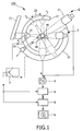
- Fig.1 shows an X-ray device 100 according to the present invention that serves for the formation of two-dimensional X-ray images, or X-ray projection images, of an object 40 to be examined, for example, a patient who is arranged on a patient table 60.
- the X-ray device includes a first imaging unit 1 having a first X-ray source 10 and a first X-ray detector 11 that are mounted so as to face one another on a C-arm 12 which itself is mounted on a stand 13 that is only partly shown.
- the C-arm 12 on the one hand can be pivoted about a horizontal axis while on the other hand it can be rotated, by means of a motor drive, for example, through 180° about its center in the direction of the double arrow 20. This movement enables the formation of a multitude of X-ray images that represent the object 40 to be examined from different reproducible projection directions r 1 , r 2 , r 3 of the first imaging unit 1.
- a second imaging unit 2 having a second X-ray source 20 and a second X-ray detector 21 that are mounted on a mounting device 22 and are capable of forming projection images of the object 40 to be examined from a fixed (which may, alternatively, also be variable if desired or necessary) X-ray position r'.
- Each of the X-ray detectors 11, 21 may be formed by an X-ray intensifier whereto there is connected a television chain whose output signals are digitized by an analog-to-digital converter 3 so as to be stored in a memory 4.
- the X-ray projection images that are acquired by the first imaging unit 1 from different positions r l ,... , r i , ..., r m can be processed by an image processing unit 5 so as to be displayed, individually or as a series of images, on a monitor 6.
- the X-ray projection images that are acquired by the second imaging unit 2 from the fixed X-ray position r' at discrete instants during the inflow of a contrast medium can also be processed by the image processing unit 5 so as to be displayed on the monitor 6.
- the individual components of the X-ray device are controlled by means of a control unit 7.
- a (first) series of X-ray projection images D l , ..., D i , ..., D m are acquired with different projection directions while the vascular tree is filled with a contrast medium (step 102) by use of the first imaging unit 1.
- a three-dimensional volume image is reconstructed from the series of (two-dimensional) X-ray projection images D by use of a reconstruction unit 51.
- the position and the orientation of the X-ray source 10 and an X-ray detector 10 are known for each projection image (for example, on the basis of a preceding calibration measurement).
- the reconstructed three-dimensional image not only shows the vascular tree (filled with contrast medium), but also other structures such as bones. Therefore, in the step 104 the three-dimensional image is segmented by use of a segmentation unit 52 in such a manner that it shows only the vascular tree while all other structures are preferably suppressed.
- segmentation can be performed by way of a thresholding operation that assigns all voxels that have a comparatively high absorption value to the vascular tree and suppresses the reproduction of all other voxels.
- Use may alternatively be made of a different segmentation method (for example, a method capable of detecting line-shaped structures) that produces more accurate segmentation but usually requires more calculation effort.
- a binary volume results in which voxels, which belong to the vascular structure are marked, e.g. by a label value 1, while the surrounding volume is marked by e.g. label value zero.
- a high-speed bi-plane flow acquisition of the vascular tree is performed during inflow of a short additional contrast agent bolus T.
- These bi-plane projections are acquired from different, preferably orthogonal, projection directions in interleaved acquisition mode, i.e. the projection images of said two series of projection images E 0 , ...., E j , ...., E n and F 0 , ...., F j , ...., F n are acquired by use of said first and second imaging units 1, 2.
- said second series of projection images E 0 - E n is acquired by use of the first imaging unit 1 where the first X-ray source 10 is at position r 2
- the third series of projection images F 0 - F n is acquired by use of the second imaging unit 2 where the X-ray source is at position r', i.e. at a position rotated by 90° about the longitudinal access of the patient 40.
- an image stacking method is, preferably but not necessarily, applied to both projection series E, F by use of an image stacking unit 53 resulting in a reference projection image per direction (one reference projection image per series E, F) showing a complete vascular system.
- An entropy method which may preferably be applied for image stacking a series of angiographic images is described in the above cited article of Schmitt H. et al. Said entropy method comprises calculation of the entropy of the time course for each image pixel. This accentuates image areas where a contrast agent bolus is passing.
- other methods such as a maximum opacity method also briefly described in said article. Further image stacking methods which might be applied are described in references cited in said article.
- step 107 the segmented 3D volume, in particular the segmented vessel tree, is then forward projected to both reference projection images obtained by the previous image stacking step by a forward projection unit 54.
- Motion which may have occurred between the acquisition of the first series of projection images D and the second and third series of projection images E, F is corrected in step 108 using a 2D or 3D motion compensation method in a motion compensation unit 56.
- a 2D or 3D motion compensation method can be used, such as a mutual information maximizing method (c.f. E. Meijering et al., Reduction of patient motion artifacts in digital subtraction angiography: Evaluation of a fast and fully automatic technique. Radiology, 219:288-293, 2001 ).
- a registration method can be used to register the forward projected images with the reference projection images.
- any kind of 2D registration method may be used.
- step 109 for each time frame (projection image) acquired with the high speed bi-plane projection series E, F, a corresponding grey value is projected to the voxel in the 3D volume image.
- it is preferably the mean from the two neighbouring time frames (due to interleaved acquisition), which is projected to the voxel in the 3D volume image.
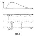
- Fig. 4 where, over time, the contrast agent (CA) bolus T and the second and third series of projection images E, F are shown, in particular the points in time at which the single projection images of said series have been acquired.
- the mean from two neighbouring projection images are then indicated by reference signs G where, for instance, G 11 means the mean of projection images E 1 and F 1 or, in general, the reference sign G xy means the mean from the projection images E x and F y .
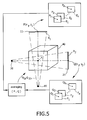
- the steps of forward projection and mapping are also illustrated in the diagram of Fig. 5 .
- the first and second X-ray sources 10, 20 and the corresponding X-ray detectors 11, 21 in positions for acquiring the second and third series of projection images according to a bi-plane mode.
- the positions of the X-ray detectors 11, 21 also indicate the position of the of the first and second, respectively, projection planes R 1 , R 2 at which the reference projection images have been obtained by the image stacking step.
- the voxel K corresponds to pixels P(x 1 , y 1 ) and Q(x 2 , y 2 ), respectively.
- Q a grey value time curve exists in the series of X-ray projection images E, F, i.e. in the series E 1 -E n the pixels P 1 -P n corresponding to pixel P are identified and their pixel values are assigned as a time series to pixel P.
- pixel Q for which the corresponding pixels Q 1 -Q n are identified in the series F 1 -F n and for which the corresponding pixel values are assigned as time series to pixel Q.
- Q the mean values of neighbouring (in time) pixel values are determined as shown in Fig. 4 , and the mean values are then mapped onto the corresponding voxel K.
- a 4D volume data set results which shows the mean of the varying grey values from the different projection directions. Due to the high-speed temporal series, time information is added to the 3D volume data set while due to the interpolation of different projection directions spatial information is added. As suggested for known flow reconstruction methods, it is feasible to apply a linear programming based optimisation scheme to correct for noise in the temporal grey value changes in 3D due to neighbouring relations of the voxels. Finally, it is possible to display (step 109) temporal and spatial grey value changes within an aneurysm by use of the method according to the present invention.
- a 4D data set of the voxel dependent grey value changes within a vessel tree and, in particular, within structures of the vessel tree which are non-tubular, such as aneurysms, results.
- a priori knowledge about the wash-in of contrast agent can be applied to some extent to resolve projection ambiguities. It is known that the arriving contrast agent bolus must create an intensity change in both projection views for a given voxel. Thus, it can be concluded that an intensity change in only one view is caused by the contrast agent arriving at a voxel which is overlapping with a given one in the projection environment.
- the present invention is preferably applied in high spatial and temporal resolution flat panel bi-plane C arm systems, in particular for obtaining a time series of 3D volume images showing the blood flow in a vascular tree of an object, in particular in non-tubular structures of the vessel tree.
- other applications are feasible as well, such as the mapping of perfusion information.
- the above explained embodiment does not limit the scope of projection, but is an example for explaining the main idea of the invention.
- the first series of X-ray projection images might be taken well in advance before that second and third series of projection images are acquired.
- other equipment for acquiring the X-ray projection images can be used, in particular for the first series, which may acquired by a CT system as well.
Description
- The present invention relates to an image processing device and a corresponding image processing method for generating a time series of 3D volume images showing the blood flow in a vascular tree of an object, based on a first series of X-ray projection images (D) of the object acquired from different projection directions and a second and a third series of X-ray projections images of the object acquired alternately at a first or second fixed projection plane, respectively, from a first or second fixed projection direction, respectively, during inflow of contrast agent into the vascular tree of the object. Further, the present invention relates to a computer program for implementing said method on a computer. In particular, the present invention relates to an X-ray device for imaging the blood flow in a vascular tree of an object.
- A method for the determination of the contrast-agent propagation in vessel trees is known from "An X-Ray based method for the determination of the contrast agent propagation in 3-D vessel structures", Schmitt, H. et al., IEEE Transactions on medical imaging, Vol. 21, No. 3, March 2002, pages 251-262. A standard 3-D rotational angiography procedure is performed to reconstruct the vessel tree in a 3-D volume. An additional fluoroscopy projection series acquired with a fixed projection angle delivers the temporal information of the bolus propagating.
- A non-interactive method for flow reconstruction in three-dimensional vessel structures is known form "Improved flow reconstruction in 3D rotational angiography (3DRA)", Grass M. et al., 2002 IEEE Nuclear science symposium and medical imaging conference, Norfolk, VA, Nov. 10-16, 2002, IEEE, Vol. 3, pages 1474-1476. The method is based on a standard 3-D rotational angiography procedure followed by the acquisition of a high-speed projection series with fixed angulation.
- A method of imaging the blood flow in a vascular tree that yields additional information concerning the vascular tree is disclosed in
WO 02/056260 A1 - However, this and other current flow reconstruction methods are based on vessel structuring and are therefore limited to tubular structures with an unambiguous connection structure of the different voxel clusters along the vascular tree. Therefore, they are not applicable to the reconstruction of, for instance, aneurismal flow at the current stage. It is thus an object of the present invention to provide an image processing device and a corresponding method which allow image reconstruction of ambiguous structures in the object of interest and, in particular, the generation of 3D volume images showing the blood flow in a vascular tree of an object even if said vascular tree comprises non-tubular structures, such as aneurysms.
- The object is achieved according to the present invention by an image processing device as claimed in
claim 1 comprising: - a reconstruction unit for reconstruction of a 3D volume image of said object from said first series of X-ray projection images,
- a segmentation unit for segmentation of the vessel tree from said 3D volume image,
- a forward projection unit for forward projection of the segmented vessel tree onto said first and projection plane, respectively, and
- a mapping unit for mapping of the image values of pixels of the vessel tree in said second and third, respectively, series of X-ray projection images onto corresponding voxels of said 3D volume image to obtain said time series of 3D volume images showing the blood flow in the vascular tree of the object.
- A corresponding image processing method is defined in
claim 11. A computer program comprising program code means for causing a computer to perform the steps of that method when said computer program is executed on a computer is defined inclaim 12, which computer program may be stored on a record carrier. - Further, the present invention also relates to an X-ray device for imaging the blood flow in a vascular tree of an object as defined in claim 9 including:
- a first imaging unit having a first X-ray source and a first X-ray detector for acquisition of a first series of X-ray projection images of the object from different projection directions and for acquisition of a second series of X-ray projections images of the object from a first fixed projection direction,
- a second imaging unit having a second X-ray source and a second X-ray detector for acquisition of a third series of X-ray projections images of the object from a second fixed projection direction,
- a control unit for controlling said first and second imaging units such that said first series of X-ray projection images is acquired before or after the second and third series of X-ray projection images are acquired and that the X-ray projection images of said second series and the X-ray projection images of said third series are alternately at a first or second fixed projection plane, respectively, acquired from different projection directions during inflow of contrast agent into the vascular tree of the object, and
- an image processing device as defined above according to the present invention for generating a time series of 3D volume images showing the blood flow in a vascular tree of an object.
- Preferred embodiments of the invention are defined in the dependent claims.
- The invention is based on the idea to use time information about the blood flow (or contrast agent flow) in the vascular tree obtained from two different projection directions which thus also include some spatial information, and to map said time and spatial information onto a 3D volume image of the object of interest resulting in a 4D data set of voxel dependent grey value changes in the vascular tree. This makes it possible to display temporal and spatial grey value changes within an aneurysm which is not possible with known flow reconstruction methods.
- According to the present invention this is obtained by use of a 3D volume image of the object which is reconstructed from a first series of X-ray projections images and from which the vessel tree is segmented. Furthermore, a second and third series of X-ray projection images, which have been alternately acquired, i.e. in interleaved acquisition mode, from different projection directions, i.e. at different projection planes, is used. Onto said projection planes the segmented vessel tree is forward projected so that the projected position of each of the segmented voxels in the projection planes is known.
- For each pixel in the projection planes a grey value time curve now exists from the time series (second and third series) of X-ray projection images showing the inflow, duration and outflow of contrast agent projected onto this pixel. Finally, the image values (grey values) of the pixels of the vessel tree in the X-ray projection images of said second and third, respectively, time series are mapped onto corresponding voxels of the 3D volume images, i.e. the grey value time curve for each pixel is projected onto the corresponding voxel in the 3D volume image to obtain a time series of 3D volume images showing the blood flow in the vascular tree of the object, i.e. to obtain a 4D volume data set.
- In a preferred embodiment an image stacking method is applied resulting in a reference projection image per projection direction showing the vascular tree. An example for an image stacking method which may be used for this purpose is described in Schmitt, H. et al. "Image Stacking with Entropy Values in Angiography", Radiology 2004; 230: 294-298. The reference projection images obtained by the image stacking are preferably needed for motion compensation. If there is no patient motion, a calibration of the system geometry is generally sufficient in order to facilitate the mapping. The forward projections are then directly made onto these reference projection images lying in the first and second, respectively, projection planes.
- According to a preferred embodiment a motion compensation unit is provided for compensation of motion of the object between the acquisition of the first series of X-ray projection images and the second and third series of X-ray projection images. Such a motion compensation is preferably applied after the segmented vessel tree has been forward projected onto the reference projection images to achieve full and accurate correspondence between the reference projection images and the forward projections. Alternatively, it is proposed to provide a registration unit for registration of the forward projected images of the 3D volume image onto the reference projection images. It is, for instance, not necessarily required that the first series of X-ray projection images is directly applied before the second and third series of X-ray projection images are acquired, but it may also be possible that said first series is acquired on another day or some time in advance before the second and third series are acquired. The registration is then required since the patient's position has been changed in the meantime.
- Preferably, means are generally provided for determine if any motion compensation or registration is required based on the forward projected images and the second and third series of projection images.
- Rather than mapping directly the image values of pixels of the vessel tree in the projection images of the second and third series onto corresponding voxels of the 3D volume image, it is proposed in a further embodiment to determine mean image values of neighboring projection images of the second and third series, i.e. a mean value is formed of an image value of an image of the second series and the subsequently acquired image of the third series, both of the same voxel, and this mean value is then mapped onto the corresponding voxel. Thus, the obtained 4D volume data set shows the mean of the varying grey values from the different projection images, said 4D volume data set having a high temporal resolution.
- Generally, two situations of averaging can be distinguished. In a first situation a part of the vessel tree is freely projected in both projection directions, so that the mean values of each two neighboring projection images (i.e. one from the first direction and the subsequent one from the other direction) are determined leading to a higher resolution in time. In a second situation there are overlapping parts of the vessel tree in one projection direction. Then, only a lower resolution in time (i.e. the resolution of the second or third series) can be obtained, and the mean values are determined for two neighboring projection images of the same series. For an aneurysm which is freely projected in both directions, the information from both directions can be used to achieve a higher spatial resolution within the aneurysm.
- Preferably, not only during the acquisition of the second and third series of X-ray projection images a contrast agent is flowing into the vascular tree, but also during acquisition of the first series of X-ray projection images the vessel tree has been completely filled with contrast agent to improve contrast in said images.
- While generally any two different projection directions are possible for obtaining said second and third series of X-ray projection images, it is advantageously proposed according to another embodiment that the two projection directions are substantially orthogonal which is often used in a bi-plane acquisition mode. This has the advantage that the overlapping of vessel structures in the projections is expected to be most efficiently reduced if orthogonal projection angles are used. Preferably, the two projection directions are selected such that, for instance in case of examination of an aneurysm, the projection directions are as orthogonal as possible and from both projection directions the aneurysm is not superposed by other vessels.
- Furthermore, according to still another embodiment, not only the vessel tree may be forward projected onto the projection planes or the reference projection images, but the complete 3D volume image can be projected onto the projection planes or the reference projection images and, further, the image values of all pixels of the projection images of the second and third series can be mapped onto the corresponding voxels of the 3D volume image instead of only mapping the image values of pixels of the vessel tree. This is, for instance, of interest for applications where information can be gathered not only from the vessels tree but also from surrounding tissue (e.g. capillary vessels in the surrounding tissue) which could not be segmented. An application where this can be used is the imaging of the head and the processing of perfusion information.
- The invention will now be explained in more detail with reference to the drawings in which
-
Fig. 1 shows a diagrammatic representation of an X-ray device according to the present invention, -
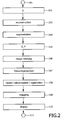
Fig. 2 shows a flow chart of the method in accordance with the invention, -
Fig. 3 a diagrammatic representation of an image processing device according to the present invention, -
Fig. 4 illustrates the acquisition of the second and third series of X-ray projection images over time and -
Fig. 5 shows a diagram illustrating the steps of forward projection and mapping. -
Fig.1 shows anX-ray device 100 according to the present invention that serves for the formation of two-dimensional X-ray images, or X-ray projection images, of anobject 40 to be examined, for example, a patient who is arranged on a patient table 60. The X-ray device includes afirst imaging unit 1 having afirst X-ray source 10 and afirst X-ray detector 11 that are mounted so as to face one another on a C-arm 12 which itself is mounted on astand 13 that is only partly shown. The C-arm 12 on the one hand can be pivoted about a horizontal axis while on the other hand it can be rotated, by means of a motor drive, for example, through 180° about its center in the direction of thedouble arrow 20. This movement enables the formation of a multitude of X-ray images that represent theobject 40 to be examined from different reproducible projection directions r1, r2, r3 of thefirst imaging unit 1. - There are also provided a second imaging unit 2 having a
second X-ray source 20 and asecond X-ray detector 21 that are mounted on a mountingdevice 22 and are capable of forming projection images of theobject 40 to be examined from a fixed (which may, alternatively, also be variable if desired or necessary) X-ray position r'. - Each of the
X-ray detectors digital converter 3 so as to be stored in amemory 4. - The X-ray projection images that are acquired by the
first imaging unit 1 from different positions rl,... , ri, ..., rm can be processed by animage processing unit 5 so as to be displayed, individually or as a series of images, on amonitor 6. The X-ray projection images that are acquired by the second imaging unit 2 from the fixed X-ray position r' at discrete instants during the inflow of a contrast medium can also be processed by theimage processing unit 5 so as to be displayed on themonitor 6. The individual components of the X-ray device are controlled by means of acontrol unit 7. - The invention will be described in detail hereinafter with reference to the flow chart shown in
Fig. 2 and the block diagram ofFig. 3 showing more details of theimage processing unit 5. After the initialization (step101), a (first) series of X-ray projection images Dl, ..., Di, ..., Dm are acquired with different projection directions while the vascular tree is filled with a contrast medium (step 102) by use of thefirst imaging unit 1. Subsequently, in step 103 a three-dimensional volume image is reconstructed from the series of (two-dimensional) X-ray projection images D by use of areconstruction unit 51. In this respect it is assumed that the position and the orientation of theX-ray source 10 and anX-ray detector 10 are known for each projection image (for example, on the basis of a preceding calibration measurement). - The reconstructed three-dimensional image not only shows the vascular tree (filled with contrast medium), but also other structures such as bones. Therefore, in the
step 104 the three-dimensional image is segmented by use of asegmentation unit 52 in such a manner that it shows only the vascular tree while all other structures are preferably suppressed. In the simplest case such segmentation can be performed by way of a thresholding operation that assigns all voxels that have a comparatively high absorption value to the vascular tree and suppresses the reproduction of all other voxels. Use may alternatively be made of a different segmentation method (for example, a method capable of detecting line-shaped structures) that produces more accurate segmentation but usually requires more calculation effort. Generally, a binary volume results in which voxels, which belong to the vascular structure are marked, e.g. by alabel value 1, while the surrounding volume is marked by e.g. label value zero. - In subsequent step 105 a high-speed bi-plane flow acquisition of the vascular tree is performed during inflow of a short additional contrast agent bolus T. These bi-plane projections are acquired from different, preferably orthogonal, projection directions in interleaved acquisition mode, i.e. the projection images of said two series of projection images E0, ...., Ej, ...., En and F0, ...., Fj, ...., Fn are acquired by use of said first and
second imaging units 1, 2. For instance, said second series of projection images E0 - En is acquired by use of thefirst imaging unit 1 where thefirst X-ray source 10 is at position r2, and the third series of projection images F0 - Fn is acquired by use of the second imaging unit 2 where the X-ray source is at position r', i.e. at a position rotated by 90° about the longitudinal access of thepatient 40. - In
step 106 an image stacking method is, preferably but not necessarily, applied to both projection series E, F by use of animage stacking unit 53 resulting in a reference projection image per direction (one reference projection image per series E, F) showing a complete vascular system. An entropy method which may preferably be applied for image stacking a series of angiographic images is described in the above cited article of Schmitt H. et al. Said entropy method comprises calculation of the entropy of the time course for each image pixel. This accentuates image areas where a contrast agent bolus is passing. Of course, other methods, such as a maximum opacity method also briefly described in said article. Further image stacking methods which might be applied are described in references cited in said article. - In
step 107 the segmented 3D volume, in particular the segmented vessel tree, is then forward projected to both reference projection images obtained by the previous image stacking step by aforward projection unit 54. - Motion which may have occurred between the acquisition of the first series of projection images D and the second and third series of projection images E, F is corrected in
step 108 using a 2D or 3D motion compensation method in amotion compensation unit 56. For this purpose any kind of motion compensation method can be used, such as a mutual information maximizing method (c.f. E. Meijering et al., Reduction of patient motion artifacts in digital subtraction angiography: Evaluation of a fast and fully automatic technique. Radiology, 219:288-293, 2001). Alternatively, a registration method can be used to register the forward projected images with the reference projection images. For this purpose any kind of 2D registration method may be used. At this stage, the projected position of each of the segmented voxels in the projection plane is known. For each pixel in the projection plane a grey value time curve exists from the high speed data acquisition of the second and third series of projection images E, F showing the inflow of contrast agent projected onto this pixel. In case no motion has occurred, no motion compensation and no registration is generally required. - Subsequently, in
step 109 and by use of amapping unit 55, for each time frame (projection image) acquired with the high speed bi-plane projection series E, F, a corresponding grey value is projected to the voxel in the 3D volume image. In more detail, it is preferably the mean from the two neighbouring time frames (due to interleaved acquisition), which is projected to the voxel in the 3D volume image. This is shown in more detail inFig. 4 where, over time, the contrast agent (CA) bolus T and the second and third series of projection images E, F are shown, in particular the points in time at which the single projection images of said series have been acquired. In the last diagram ofFig. 4 the mean from two neighbouring projection images are then indicated by reference signs G where, for instance, G11 means the mean of projection images E1 and F1 or, in general, the reference sign Gxy means the mean from the projection images Ex and Fy. - The steps of forward projection and mapping are also illustrated in the diagram of
Fig. 5 . There is shown, in abstract form, theobject 40 to be examined from which a particular voxel K shall be considered in more detail. Further shown are the first andsecond X-ray sources corresponding X-ray detectors X-ray detectors Fig. 4 , and the mean values are then mapped onto the corresponding voxel K. - Thus, a 4D volume data set results which shows the mean of the varying grey values from the different projection directions. Due to the high-speed temporal series, time information is added to the 3D volume data set while due to the interpolation of different projection directions spatial information is added. As suggested for known flow reconstruction methods, it is feasible to apply a linear programming based optimisation scheme to correct for noise in the temporal grey value changes in 3D due to neighbouring relations of the voxels. Finally, it is possible to display (step 109) temporal and spatial grey value changes within an aneurysm by use of the method according to the present invention. As a result, a 4D data set of the voxel dependent grey value changes within a vessel tree and, in particular, within structures of the vessel tree which are non-tubular, such as aneurysms, results. Finally, in
step 111, the method is terminated. - Preferably, as an addition, a priori knowledge about the wash-in of contrast agent can be applied to some extent to resolve projection ambiguities. It is known that the arriving contrast agent bolus must create an intensity change in both projection views for a given voxel. Thus, it can be concluded that an intensity change in only one view is caused by the contrast agent arriving at a voxel which is overlapping with a given one in the projection environment.
- The present invention is preferably applied in high spatial and temporal resolution flat panel bi-plane C arm systems, in particular for obtaining a time series of 3D volume images showing the blood flow in a vascular tree of an object, in particular in non-tubular structures of the vessel tree. However, other applications are feasible as well, such as the mapping of perfusion information. It shall be understood that the above explained embodiment does not limit the scope of projection, but is an example for explaining the main idea of the invention. A multitude of variations are possible. For instance, the first series of X-ray projection images might be taken well in advance before that second and third series of projection images are acquired. Furthermore, other equipment for acquiring the X-ray projection images can be used, in particular for the first series, which may acquired by a CT system as well.
Claims (12)
- An image processing device (5) for generating a time series of 3D volume images showing the blood flow in a vascular tree of an object (40), based on a first series of X-ray projection images (D) of the object acquired from different projection directions and a second and a third series of X-ray projections images (E, F) of the object acquired alternately at a first or second fixed projection plane, respectively, during inflow of contrast agent into the vascular tree of the object, said device comprising:- a reconstruction unit (51) for reconstruction of a 3 D volume image of said object from said first series of X-ray projection images (D),- a segmentation unit (52) for segmentation of the vessel tree from said 3D volume image,- a forward projection unit (54) for forward projection of the segmented vessel tree onto said first and second projection plane (R1, R2), respectively, and- a mapping unit (55) for mapping of the image values of pixels of the vessel tree in said second and third, respectively, series of X-ray projection images onto corresponding voxels of said 3D volume image to obtain said time series of 3D volume images showing the blood flow in the vascular tree of the object.
- Image processing device as claimed in claim 1,
further comprising an image stacking unit (53) for stacking of said second and third, respectively, series of X-ray projection images (E, F) to obtain a reference projection image for each of a first and second fixed projection direction at said first and second projection planes (R1, R2), and
wherein said forward projection unit (54) is adapted for forward projection of the segmented vessel tree onto said reference projection images. - Image processing device as claimed in claim 2, further comprising a motion compensation unit (56) for compensation of motion of the object between the acquisition of the first series of X-ray projection images and the second and third series of X-ray projection images.
- Image processing device as claimed in claim 2, further comprising a registration unit (56) for registration of said forward projected images of said 3D volume image onto said reference projection images.
- Image processing device as claimed in claim 1, wherein said mapping unit (55) is adapted for forming, for the pixels of the projection images of the second and third series to be mapped onto corresponding voxels of the 3D volume image, the mean image value of two image values of subsequently acquired X-ray projection images (E, F) from said second and third series and for mapping said mean image values onto the corresponding voxels of the 3D volume image.
- Image processing device as claimed in claim 1, wherein said first series of X-ray projection images (D) has been acquired while the vessel tree has been filled with contrast agent.
- Image processing device as claimed in claim 1, wherein said second series of X-ray projection images (E) has been acquired from a projection direction orthogonal to the projection direction from which the third series of X-ray projection images (F) has been acquired.
- Image processing device as claimed in claim 1, wherein
said forward projection unit (54) is adapted for forward projection of all voxels of the 3D volume image onto said first and second projection plane (R1, R2), respectively, and
said mapping unit (55) is adapted for mapping of the image values of all pixels of the X-ray projection images in said second and third, respectively, series onto the corresponding voxels of said 3D volume image. - An X-ray device for imaging the blood flow in a vascular tree of an object including:- a first imaging unit (1) having a first X-ray source (10) and a first X-ray detector (11) for acquisition of a first series of X-ray projection images (D) of the object from different projection directions and for acquisition of a second series of X-ray projections images (E) of the object from a first fixed projection direction,- a second imaging unit (2) having a second X-ray source (20) and a second X-ray detector (21) for acquisition of a third series of X-ray projections images (F) of the object from a second fixed projection direction,- a control unit (7) for controlling said first and second imaging units (1, 2) such that said first series of X-ray projection images (D) is acquired before or after the second and third series of X-ray projection images (E, F) are acquired and that the X-ray projection images (E) of said second series and the X-ray projection images (F) of said third series are alternately acquired at a first or second fixed projection plane, respectively, from different projection directions during inflow of contrast agent into the vascular tree of the object, and- an image processing device (5) as claimed in claim 1 for generating a time series of 3D volume images showing the blood flow in a vascular tree of an object.
- X-ray device as claimed in claim 9 wherein said first and second imaging unit are a bi-plane imaging unit.
- An image processing method for generating a time series of 3D volume images showing the blood flow in a vascular tree of an object, based on a first series of X-ray projection images (D) of the object acquired from different projection directions and a second and a third series of X-ray projections images (E, F) of the object acquired alternately at a first or second fixed projection plane, respectively, from a first or second fixed projection direction, respectively, during inflow of contrast agent into the vascular tree of the object, said method comprising the steps of:- reconstructing a 3D volume image of said object from said first series of X-ray projection images (D),- segmenting the vessel tree from said 3D volume image,- forward projection of the segmented vessel tree onto said first and second projection plane (R1, R2), respectively, and- mapping of the image values of pixels of the vessel tree in said second and third, respectively, series of X-ray projection images onto corresponding voxels of said 3D volume image to obtain said time series of 3D volume images showing the blood flow in the vascular tree of the object.
- Computer program comprising program code means for causing a computer to perform the steps of the method as claimed in claim 11, when said computer program is executed on a computer.
Priority Applications (2)
| Application Number | Priority Date | Filing Date | Title |
|---|---|---|---|
| PL06727806T PL1869643T3 (en) | 2005-04-07 | 2006-04-03 | Image processing device and method for blood flow imaging |
| EP06727806.9A EP1869643B1 (en) | 2005-04-07 | 2006-04-03 | Image processing device and method for blood flow imaging |
Applications Claiming Priority (3)
| Application Number | Priority Date | Filing Date | Title |
|---|---|---|---|
| EP05102736 | 2005-04-07 | ||
| EP06727806.9A EP1869643B1 (en) | 2005-04-07 | 2006-04-03 | Image processing device and method for blood flow imaging |
| PCT/IB2006/051004 WO2006106470A2 (en) | 2005-04-07 | 2006-04-03 | Image processing device and method for blood flow imaging |
Publications (2)
| Publication Number | Publication Date |
|---|---|
| EP1869643A2 EP1869643A2 (en) | 2007-12-26 |
| EP1869643B1 true EP1869643B1 (en) | 2014-05-07 |
Family
ID=36660663
Family Applications (1)
| Application Number | Title | Priority Date | Filing Date |
|---|---|---|---|
| EP06727806.9A Active EP1869643B1 (en) | 2005-04-07 | 2006-04-03 | Image processing device and method for blood flow imaging |
Country Status (5)
| Country | Link |
|---|---|
| US (1) | US8009885B2 (en) |
| EP (1) | EP1869643B1 (en) |
| CN (1) | CN101156174B (en) |
| PL (1) | PL1869643T3 (en) |
| WO (1) | WO2006106470A2 (en) |
Families Citing this family (26)
| Publication number | Priority date | Publication date | Assignee | Title |
|---|---|---|---|---|
| US8218844B2 (en) * | 2008-02-21 | 2012-07-10 | Siemens Aktiengesellschaft | Method for generating analytical tool for analyzing abnormalities in human organs |
| US8428327B2 (en) * | 2008-05-08 | 2013-04-23 | Oslo Universitetssykehus Hf | Vessel segmentation in DCE MR imaging |
| US20100053209A1 (en) * | 2008-08-29 | 2010-03-04 | Siemens Medical Solutions Usa, Inc. | System for Processing Medical Image data to Provide Vascular Function Information |
| ES2341079B1 (en) * | 2008-12-11 | 2011-07-13 | Fundacio Clinic Per A La Recerca Biomedica | EQUIPMENT FOR IMPROVED VISION BY INFRARED VASCULAR STRUCTURES, APPLICABLE TO ASSIST PHYTOSCOPIC, LAPAROSCOPIC AND ENDOSCOPIC INTERVENTIONS AND SIGNAL TREATMENT PROCESS TO IMPROVE SUCH VISION. |
| DE102008064127B4 (en) * | 2008-12-19 | 2014-10-16 | Siemens Aktiengesellschaft | Evaluation method for data records of an examination object with backprojection of two-dimensionally determined functional evaluation results into the three-dimensional data carrier and computer provided with a corresponding computer program |
| JP5729907B2 (en) * | 2009-02-23 | 2015-06-03 | 株式会社東芝 | X-ray diagnostic equipment |
| ES2659090T3 (en) | 2009-03-20 | 2018-03-13 | Orthoscan Incorporated | Mobile image capture device |
| US8654119B2 (en) * | 2009-08-17 | 2014-02-18 | Mistretta Medical, Llc | System and method for four dimensional angiography and fluoroscopy |
| US8643642B2 (en) | 2009-08-17 | 2014-02-04 | Mistretta Medical, Llc | System and method of time-resolved, three-dimensional angiography |
| US20110235885A1 (en) * | 2009-08-31 | 2011-09-29 | Siemens Medical Solutions Usa, Inc. | System for Providing Digital Subtraction Angiography (DSA) Medical Images |
| US8787521B2 (en) * | 2009-12-23 | 2014-07-22 | General Electric Company | System and method of iterative image reconstruction for computed tomography |
| CN101799935B (en) * | 2009-12-31 | 2011-09-14 | 华中科技大学 | Dynamic three-dimensional reconstruction method of single-arm X-ray angiogram maps |
| WO2011091300A2 (en) | 2010-01-24 | 2011-07-28 | Mistretta Medical, Llc | System and method for implementation of 4d time-energy subtraction computed tomography |
| JP5584006B2 (en) * | 2010-03-31 | 2014-09-03 | 富士フイルム株式会社 | Projection image generation apparatus, projection image generation program, and projection image generation method |
| DE102010040976A1 (en) * | 2010-09-17 | 2012-03-22 | Siemens Aktiengesellschaft | X-ray imaging method |
| US8768031B2 (en) | 2010-10-01 | 2014-07-01 | Mistretta Medical, Llc | Time resolved digital subtraction angiography perfusion measurement method, apparatus and system |
| WO2012082799A1 (en) | 2010-12-13 | 2012-06-21 | Orthoscan, Inc. | Mobile fluoroscopic imaging system |
| CN103619237B (en) | 2011-06-15 | 2016-03-16 | 米斯特雷塔医疗有限公司 | For 4D angio radiography and fluoroscopic system and method |
| DE102012203751A1 (en) * | 2012-03-09 | 2013-09-12 | Siemens Aktiengesellschaft | Method for determining a four-dimensional angiography data record describing the contrast agent flow |
| DE102012216652B4 (en) * | 2012-09-18 | 2023-01-26 | Siemens Healthcare Gmbh | Angiographic examination procedure |
| US9091628B2 (en) | 2012-12-21 | 2015-07-28 | L-3 Communications Security And Detection Systems, Inc. | 3D mapping with two orthogonal imaging views |
| US9730662B2 (en) * | 2014-01-17 | 2017-08-15 | Siemens Medical Solutions Usa, Inc. | System and method for tracking blood flow |
| CN107111875B (en) * | 2014-12-09 | 2021-10-08 | 皇家飞利浦有限公司 | Feedback for multi-modal auto-registration |
| US9672641B2 (en) * | 2015-07-09 | 2017-06-06 | Sirona Dental Systems Gmbh | Method, apparatus, and computer readable medium for removing unwanted objects from a tomogram |
| DE102015224176A1 (en) * | 2015-12-03 | 2017-06-08 | Siemens Healthcare Gmbh | Tomography system and method for generating a sequence of volume images of a vascular system |
| CN109448072B (en) * | 2017-11-30 | 2023-05-09 | 科亚医疗科技股份有限公司 | Computer-implemented method and apparatus for three-dimensional vascular reconstruction using contrast images |
Family Cites Families (7)
| Publication number | Priority date | Publication date | Assignee | Title |
|---|---|---|---|---|
| US4430079A (en) * | 1978-11-08 | 1984-02-07 | Minnesota Mining And Manufacturing Company | Fluid dispensing device |
| US5590654A (en) * | 1993-06-07 | 1997-01-07 | Prince; Martin R. | Method and apparatus for magnetic resonance imaging of arteries using a magnetic resonance contrast agent |
| US5579767A (en) * | 1993-06-07 | 1996-12-03 | Prince; Martin R. | Method for imaging abdominal aorta and aortic aneurysms |
| DE10000185A1 (en) * | 2000-01-05 | 2001-07-12 | Philips Corp Intellectual Pty | Method for displaying the time course of the blood flow in an examination object |
| DE10100572A1 (en) | 2001-01-09 | 2002-07-11 | Philips Corp Intellectual Pty | Method for displaying blood flow in a vascular tree |
| WO2004068406A2 (en) * | 2003-01-30 | 2004-08-12 | Chase Medical, L.P. | A method and system for image processing and contour assessment |
| US7558618B1 (en) * | 2005-01-18 | 2009-07-07 | Darin S Williams | Method for extracting images of vascular structure and blood flow from image sequences |
-
2006
- 2006-04-03 CN CN200680011153XA patent/CN101156174B/en not_active Expired - Fee Related
- 2006-04-03 EP EP06727806.9A patent/EP1869643B1/en active Active
- 2006-04-03 PL PL06727806T patent/PL1869643T3/en unknown
- 2006-04-03 WO PCT/IB2006/051004 patent/WO2006106470A2/en not_active Application Discontinuation
- 2006-04-03 US US11/910,477 patent/US8009885B2/en active Active
Also Published As
| Publication number | Publication date |
|---|---|
| CN101156174B (en) | 2012-12-05 |
| CN101156174A (en) | 2008-04-02 |
| WO2006106470A2 (en) | 2006-10-12 |
| EP1869643A2 (en) | 2007-12-26 |
| WO2006106470A3 (en) | 2007-03-01 |
| US20080192997A1 (en) | 2008-08-14 |
| US8009885B2 (en) | 2011-08-30 |
| PL1869643T3 (en) | 2014-09-30 |
Similar Documents
| Publication | Publication Date | Title |
|---|---|---|
| EP1869643B1 (en) | Image processing device and method for blood flow imaging | |
| US20200268335A1 (en) | Medical image processing apparatus, x-ray diagnostic apparatus, medical image processing method and x-ray diagnostic method | |
| US7269246B2 (en) | X-ray angiography apparatus | |
| US20100201786A1 (en) | Method and apparatus for reconstructing an image | |
| US6823204B2 (en) | Method of imaging the blood flow in a vascular tree | |
| NL1024854C2 (en) | Methods and device for calculating volumetric perfusion. | |
| JP5068516B2 (en) | Method and system for displaying medical images | |
| US20080267455A1 (en) | Method for Movement Compensation of Image Data | |
| CN1846618A (en) | Method for mathematical compensation of a periodic movement of an organ and image shooting system | |
| CN111540025B (en) | Predicting images for image processing | |
| EP2863799B1 (en) | Temporal anatomical target tagging in angiograms | |
| US20080019474A1 (en) | X-ray ct scanner and data processing method of x-ray ct scanner | |
| US20080009698A1 (en) | Method and device for visualizing objects | |
| US10083511B2 (en) | Angiographic roadmapping mask | |
| CN104783825A (en) | Method and apparatus for generating 2D projection image of vascular system | |
| US20100014726A1 (en) | Hierarchical motion estimation | |
| US8855391B2 (en) | Operating method for an imaging system for the time-resolved mapping of an iteratively moving examination object | |
| KR101665513B1 (en) | Computer tomography apparatus and method for reconstructing a computer tomography image thereof | |
| US8036453B2 (en) | Analytical method for a number of two-dimensional projection images of a three-dimensional examination object | |
| JP6479919B2 (en) | Reconstruction of flow data | |
| CN108027959B (en) | Fluorescence imaging middle and low frame rate spatial flicker removal | |
| EP4202838A1 (en) | 3d dsa image reconstruction | |
| CN117788680A (en) | Vascular image processing method, vascular image processing device, vascular image processing computer equipment and storage medium |
Legal Events
| Date | Code | Title | Description |
|---|---|---|---|
| PUAI | Public reference made under article 153(3) epc to a published international application that has entered the european phase |
Free format text: ORIGINAL CODE: 0009012 |
|
| 17P | Request for examination filed |
Effective date: 20071107 |
|
| AK | Designated contracting states |
Kind code of ref document: A2 Designated state(s): AT BE BG CH CY CZ DE DK EE ES FI FR GB GR HU IE IS IT LI LT LU LV MC NL PL PT RO SE SI SK TR |
|
| 17Q | First examination report despatched |
Effective date: 20080326 |
|
| DAX | Request for extension of the european patent (deleted) | ||
| RAP1 | Party data changed (applicant data changed or rights of an application transferred) |
Owner name: PHILIPS INTELLECTUAL PROPERTY & STANDARDS GMBH Owner name: KONINKLIJKE PHILIPS N.V. |
|
| GRAP | Despatch of communication of intention to grant a patent |
Free format text: ORIGINAL CODE: EPIDOSNIGR1 |
|
| INTG | Intention to grant announced |
Effective date: 20131114 |
|
| GRAS | Grant fee paid |
Free format text: ORIGINAL CODE: EPIDOSNIGR3 |
|
| GRAA | (expected) grant |
Free format text: ORIGINAL CODE: 0009210 |
|
| AK | Designated contracting states |
Kind code of ref document: B1 Designated state(s): AT BE BG CH CY CZ DE DK EE ES FI FR GB GR HU IE IS IT LI LT LU LV MC NL PL PT RO SE SI SK TR |
|
| REG | Reference to a national code |
Ref country code: GB Ref legal event code: FG4D |
|
| REG | Reference to a national code |
Ref country code: DE Ref legal event code: R081 Ref document number: 602006041442 Country of ref document: DE Owner name: PHILIPS GMBH, DE Free format text: FORMER OWNERS: PHILIPS INTELLECTUAL PROPERTY & STANDARDS GMBH, 20099 HAMBURG, DE; KONINKLIJKE PHILIPS ELECTRONICS N.V., EINDHOVEN, NL |
|
| REG | Reference to a national code |
Ref country code: AT Ref legal event code: REF Ref document number: 667187 Country of ref document: AT Kind code of ref document: T Effective date: 20140515 |
|
| REG | Reference to a national code |
Ref country code: IE Ref legal event code: FG4D |
|
| REG | Reference to a national code |
Ref country code: GB Ref legal event code: 746 Effective date: 20140521 |
|
| REG | Reference to a national code |
Ref country code: DE Ref legal event code: R096 Ref document number: 602006041442 Country of ref document: DE Effective date: 20140618 |
|
| REG | Reference to a national code |
Ref country code: AT Ref legal event code: MK05 Ref document number: 667187 Country of ref document: AT Kind code of ref document: T Effective date: 20140507 |
|
| REG | Reference to a national code |
Ref country code: PL Ref legal event code: T3 |
|
| REG | Reference to a national code |
Ref country code: NL Ref legal event code: VDEP Effective date: 20140507 |
|
| REG | Reference to a national code |
Ref country code: LT Ref legal event code: MG4D |
|
| PG25 | Lapsed in a contracting state [announced via postgrant information from national office to epo] |
Ref country code: FI Free format text: LAPSE BECAUSE OF FAILURE TO SUBMIT A TRANSLATION OF THE DESCRIPTION OR TO PAY THE FEE WITHIN THE PRESCRIBED TIME-LIMIT Effective date: 20140507 Ref country code: IS Free format text: LAPSE BECAUSE OF FAILURE TO SUBMIT A TRANSLATION OF THE DESCRIPTION OR TO PAY THE FEE WITHIN THE PRESCRIBED TIME-LIMIT Effective date: 20140907 Ref country code: CY Free format text: LAPSE BECAUSE OF FAILURE TO SUBMIT A TRANSLATION OF THE DESCRIPTION OR TO PAY THE FEE WITHIN THE PRESCRIBED TIME-LIMIT Effective date: 20140507 Ref country code: LT Free format text: LAPSE BECAUSE OF FAILURE TO SUBMIT A TRANSLATION OF THE DESCRIPTION OR TO PAY THE FEE WITHIN THE PRESCRIBED TIME-LIMIT Effective date: 20140507 Ref country code: GR Free format text: LAPSE BECAUSE OF FAILURE TO SUBMIT A TRANSLATION OF THE DESCRIPTION OR TO PAY THE FEE WITHIN THE PRESCRIBED TIME-LIMIT Effective date: 20140808 |
|
| PG25 | Lapsed in a contracting state [announced via postgrant information from national office to epo] |
Ref country code: ES Free format text: LAPSE BECAUSE OF FAILURE TO SUBMIT A TRANSLATION OF THE DESCRIPTION OR TO PAY THE FEE WITHIN THE PRESCRIBED TIME-LIMIT Effective date: 20140507 Ref country code: SE Free format text: LAPSE BECAUSE OF FAILURE TO SUBMIT A TRANSLATION OF THE DESCRIPTION OR TO PAY THE FEE WITHIN THE PRESCRIBED TIME-LIMIT Effective date: 20140507 Ref country code: LV Free format text: LAPSE BECAUSE OF FAILURE TO SUBMIT A TRANSLATION OF THE DESCRIPTION OR TO PAY THE FEE WITHIN THE PRESCRIBED TIME-LIMIT Effective date: 20140507 Ref country code: AT Free format text: LAPSE BECAUSE OF FAILURE TO SUBMIT A TRANSLATION OF THE DESCRIPTION OR TO PAY THE FEE WITHIN THE PRESCRIBED TIME-LIMIT Effective date: 20140507 |
|
| PG25 | Lapsed in a contracting state [announced via postgrant information from national office to epo] |
Ref country code: PT Free format text: LAPSE BECAUSE OF FAILURE TO SUBMIT A TRANSLATION OF THE DESCRIPTION OR TO PAY THE FEE WITHIN THE PRESCRIBED TIME-LIMIT Effective date: 20140908 |
|
| PG25 | Lapsed in a contracting state [announced via postgrant information from national office to epo] |
Ref country code: DK Free format text: LAPSE BECAUSE OF FAILURE TO SUBMIT A TRANSLATION OF THE DESCRIPTION OR TO PAY THE FEE WITHIN THE PRESCRIBED TIME-LIMIT Effective date: 20140507 Ref country code: SK Free format text: LAPSE BECAUSE OF FAILURE TO SUBMIT A TRANSLATION OF THE DESCRIPTION OR TO PAY THE FEE WITHIN THE PRESCRIBED TIME-LIMIT Effective date: 20140507 Ref country code: CZ Free format text: LAPSE BECAUSE OF FAILURE TO SUBMIT A TRANSLATION OF THE DESCRIPTION OR TO PAY THE FEE WITHIN THE PRESCRIBED TIME-LIMIT Effective date: 20140507 Ref country code: EE Free format text: LAPSE BECAUSE OF FAILURE TO SUBMIT A TRANSLATION OF THE DESCRIPTION OR TO PAY THE FEE WITHIN THE PRESCRIBED TIME-LIMIT Effective date: 20140507 Ref country code: RO Free format text: LAPSE BECAUSE OF FAILURE TO SUBMIT A TRANSLATION OF THE DESCRIPTION OR TO PAY THE FEE WITHIN THE PRESCRIBED TIME-LIMIT Effective date: 20140507 Ref country code: BE Free format text: LAPSE BECAUSE OF FAILURE TO SUBMIT A TRANSLATION OF THE DESCRIPTION OR TO PAY THE FEE WITHIN THE PRESCRIBED TIME-LIMIT Effective date: 20140507 |
|
| REG | Reference to a national code |
Ref country code: DE Ref legal event code: R097 Ref document number: 602006041442 Country of ref document: DE |
|
| PG25 | Lapsed in a contracting state [announced via postgrant information from national office to epo] |
Ref country code: NL Free format text: LAPSE BECAUSE OF FAILURE TO SUBMIT A TRANSLATION OF THE DESCRIPTION OR TO PAY THE FEE WITHIN THE PRESCRIBED TIME-LIMIT Effective date: 20140507 |
|
| PLBE | No opposition filed within time limit |
Free format text: ORIGINAL CODE: 0009261 |
|
| STAA | Information on the status of an ep patent application or granted ep patent |
Free format text: STATUS: NO OPPOSITION FILED WITHIN TIME LIMIT |
|
| 26N | No opposition filed |
Effective date: 20150210 |
|
| PG25 | Lapsed in a contracting state [announced via postgrant information from national office to epo] |
Ref country code: IT Free format text: LAPSE BECAUSE OF FAILURE TO SUBMIT A TRANSLATION OF THE DESCRIPTION OR TO PAY THE FEE WITHIN THE PRESCRIBED TIME-LIMIT Effective date: 20140507 |
|
| REG | Reference to a national code |
Ref country code: DE Ref legal event code: R097 Ref document number: 602006041442 Country of ref document: DE Effective date: 20150210 |
|
| PGFP | Annual fee paid to national office [announced via postgrant information from national office to epo] |
Ref country code: PL Payment date: 20150327 Year of fee payment: 10 |
|
| REG | Reference to a national code |
Ref country code: DE Ref legal event code: R082 Ref document number: 602006041442 Country of ref document: DE Representative=s name: MEISSNER, BOLTE & PARTNER GBR, DE Ref country code: DE Ref legal event code: R081 Ref document number: 602006041442 Country of ref document: DE Owner name: PHILIPS GMBH, DE Free format text: FORMER OWNER: PHILIPS INTELLECTUAL PROPERTY & STANDARDS GMBH, 20099 HAMBURG, DE Ref country code: DE Ref legal event code: R082 Ref document number: 602006041442 Country of ref document: DE Representative=s name: MEISSNER BOLTE PATENTANWAELTE RECHTSANWAELTE P, DE |
|
| PG25 | Lapsed in a contracting state [announced via postgrant information from national office to epo] |
Ref country code: SI Free format text: LAPSE BECAUSE OF FAILURE TO SUBMIT A TRANSLATION OF THE DESCRIPTION OR TO PAY THE FEE WITHIN THE PRESCRIBED TIME-LIMIT Effective date: 20140507 |
|
| PG25 | Lapsed in a contracting state [announced via postgrant information from national office to epo] |
Ref country code: LU Free format text: LAPSE BECAUSE OF FAILURE TO SUBMIT A TRANSLATION OF THE DESCRIPTION OR TO PAY THE FEE WITHIN THE PRESCRIBED TIME-LIMIT Effective date: 20150403 Ref country code: MC Free format text: LAPSE BECAUSE OF FAILURE TO SUBMIT A TRANSLATION OF THE DESCRIPTION OR TO PAY THE FEE WITHIN THE PRESCRIBED TIME-LIMIT Effective date: 20140507 |
|
| REG | Reference to a national code |
Ref country code: CH Ref legal event code: PL |
|
| REG | Reference to a national code |
Ref country code: IE Ref legal event code: MM4A |
|
| PG25 | Lapsed in a contracting state [announced via postgrant information from national office to epo] |
Ref country code: LI Free format text: LAPSE BECAUSE OF NON-PAYMENT OF DUE FEES Effective date: 20150430 Ref country code: CH Free format text: LAPSE BECAUSE OF NON-PAYMENT OF DUE FEES Effective date: 20150430 |
|
| REG | Reference to a national code |
Ref country code: FR Ref legal event code: ST Effective date: 20151231 |
|
| PG25 | Lapsed in a contracting state [announced via postgrant information from national office to epo] |
Ref country code: FR Free format text: LAPSE BECAUSE OF NON-PAYMENT OF DUE FEES Effective date: 20150430 |
|
| PG25 | Lapsed in a contracting state [announced via postgrant information from national office to epo] |
Ref country code: IE Free format text: LAPSE BECAUSE OF NON-PAYMENT OF DUE FEES Effective date: 20150403 |
|
| PG25 | Lapsed in a contracting state [announced via postgrant information from national office to epo] |
Ref country code: HU Free format text: LAPSE BECAUSE OF FAILURE TO SUBMIT A TRANSLATION OF THE DESCRIPTION OR TO PAY THE FEE WITHIN THE PRESCRIBED TIME-LIMIT; INVALID AB INITIO Effective date: 20060403 Ref country code: BG Free format text: LAPSE BECAUSE OF FAILURE TO SUBMIT A TRANSLATION OF THE DESCRIPTION OR TO PAY THE FEE WITHIN THE PRESCRIBED TIME-LIMIT Effective date: 20140507 |
|
| PG25 | Lapsed in a contracting state [announced via postgrant information from national office to epo] |
Ref country code: TR Free format text: LAPSE BECAUSE OF FAILURE TO SUBMIT A TRANSLATION OF THE DESCRIPTION OR TO PAY THE FEE WITHIN THE PRESCRIBED TIME-LIMIT Effective date: 20140507 Ref country code: PL Free format text: LAPSE BECAUSE OF NON-PAYMENT OF DUE FEES Effective date: 20160403 |
|
| REG | Reference to a national code |
Ref country code: DE Ref legal event code: R084 Ref document number: 602006041442 Country of ref document: DE |
|
| REG | Reference to a national code |
Ref country code: DE Ref legal event code: R082 Ref document number: 602006041442 Country of ref document: DE Representative=s name: MEISSNER BOLTE PATENTANWAELTE RECHTSANWAELTE P, DE Ref country code: DE Ref legal event code: R081 Ref document number: 602006041442 Country of ref document: DE Owner name: PHILIPS GMBH, DE Free format text: FORMER OWNER: PHILIPS GMBH, 20099 HAMBURG, DE |
|
| PGFP | Annual fee paid to national office [announced via postgrant information from national office to epo] |
Ref country code: GB Payment date: 20220419 Year of fee payment: 17 |
|
| PGFP | Annual fee paid to national office [announced via postgrant information from national office to epo] |
Ref country code: DE Payment date: 20220628 Year of fee payment: 18 |
|
| GBPC | Gb: european patent ceased through non-payment of renewal fee |
Effective date: 20230403 |
|
| PG25 | Lapsed in a contracting state [announced via postgrant information from national office to epo] |
Ref country code: GB Free format text: LAPSE BECAUSE OF NON-PAYMENT OF DUE FEES Effective date: 20230403 |
|
| PG25 | Lapsed in a contracting state [announced via postgrant information from national office to epo] |
Ref country code: GB Free format text: LAPSE BECAUSE OF NON-PAYMENT OF DUE FEES Effective date: 20230403 |