EP1868487B1 - Intracorporeal videocapsule with swiveling and rotating image pickup - Google Patents
Intracorporeal videocapsule with swiveling and rotating image pickup Download PDFInfo
- Publication number
- EP1868487B1 EP1868487B1 EP06724010A EP06724010A EP1868487B1 EP 1868487 B1 EP1868487 B1 EP 1868487B1 EP 06724010 A EP06724010 A EP 06724010A EP 06724010 A EP06724010 A EP 06724010A EP 1868487 B1 EP1868487 B1 EP 1868487B1
- Authority
- EP
- European Patent Office
- Prior art keywords
- probe
- image pickup
- pickup unit
- motor
- housing
- Prior art date
- Legal status (The legal status is an assumption and is not a legal conclusion. Google has not performed a legal analysis and makes no representation as to the accuracy of the status listed.)
- Ceased
Links
Images

Classifications
-
- A—HUMAN NECESSITIES
- A61—MEDICAL OR VETERINARY SCIENCE; HYGIENE
- A61B—DIAGNOSIS; SURGERY; IDENTIFICATION
- A61B1/00—Instruments for performing medical examinations of the interior of cavities or tubes of the body by visual or photographical inspection, e.g. endoscopes; Illuminating arrangements therefor
- A61B1/04—Instruments for performing medical examinations of the interior of cavities or tubes of the body by visual or photographical inspection, e.g. endoscopes; Illuminating arrangements therefor combined with photographic or television appliances
- A61B1/041—Capsule endoscopes for imaging
-
- A—HUMAN NECESSITIES
- A61—MEDICAL OR VETERINARY SCIENCE; HYGIENE
- A61B—DIAGNOSIS; SURGERY; IDENTIFICATION
- A61B1/00—Instruments for performing medical examinations of the interior of cavities or tubes of the body by visual or photographical inspection, e.g. endoscopes; Illuminating arrangements therefor
- A61B1/00163—Optical arrangements
- A61B1/00174—Optical arrangements characterised by the viewing angles
- A61B1/00183—Optical arrangements characterised by the viewing angles for variable viewing angles
-
- A—HUMAN NECESSITIES
- A61—MEDICAL OR VETERINARY SCIENCE; HYGIENE
- A61B—DIAGNOSIS; SURGERY; IDENTIFICATION
- A61B1/00—Instruments for performing medical examinations of the interior of cavities or tubes of the body by visual or photographical inspection, e.g. endoscopes; Illuminating arrangements therefor
- A61B1/00002—Operational features of endoscopes
- A61B1/00011—Operational features of endoscopes characterised by signal transmission
- A61B1/00016—Operational features of endoscopes characterised by signal transmission using wireless means
-
- A—HUMAN NECESSITIES
- A61—MEDICAL OR VETERINARY SCIENCE; HYGIENE
- A61B—DIAGNOSIS; SURGERY; IDENTIFICATION
- A61B1/00—Instruments for performing medical examinations of the interior of cavities or tubes of the body by visual or photographical inspection, e.g. endoscopes; Illuminating arrangements therefor
- A61B1/00002—Operational features of endoscopes
- A61B1/00025—Operational features of endoscopes characterised by power management
- A61B1/00027—Operational features of endoscopes characterised by power management characterised by power supply
- A61B1/00029—Operational features of endoscopes characterised by power management characterised by power supply externally powered, e.g. wireless
-
- A—HUMAN NECESSITIES
- A61—MEDICAL OR VETERINARY SCIENCE; HYGIENE
- A61B—DIAGNOSIS; SURGERY; IDENTIFICATION
- A61B1/00—Instruments for performing medical examinations of the interior of cavities or tubes of the body by visual or photographical inspection, e.g. endoscopes; Illuminating arrangements therefor
- A61B1/00002—Operational features of endoscopes
- A61B1/00025—Operational features of endoscopes characterised by power management
- A61B1/00027—Operational features of endoscopes characterised by power management characterised by power supply
- A61B1/00032—Operational features of endoscopes characterised by power management characterised by power supply internally powered
-
- A—HUMAN NECESSITIES
- A61—MEDICAL OR VETERINARY SCIENCE; HYGIENE
- A61B—DIAGNOSIS; SURGERY; IDENTIFICATION
- A61B2560/00—Constructional details of operational features of apparatus; Accessories for medical measuring apparatus
- A61B2560/02—Operational features
- A61B2560/0204—Operational features of power management
- A61B2560/0214—Operational features of power management of power generation or supply
- A61B2560/0219—Operational features of power management of power generation or supply of externally powered implanted units
Definitions
- the present invention relates to an intracorporeal probe, for example preferably for examining hollow organs or natural or artificially created body cavities in the human or animal body, the probe being designed in the form of a capsule that can be introduced into the body without external connecting elements, comprising a housing having an elongated shape and an image pickup unit inside the housing that is designed for optically recording, for example imaging, a region (termed pickup region below) outside the probe, the image picKup unit being held in a fashion capable of moving inside the housing in order to vary the picKup region by means of such a movement.
- An intracorporeal probe of the aforesaid type is known in general, for example from US 2005/0043583 A1 or DE 101 46 197 .
- EP-A-0 667 115 also discloses an intracorporeal probe that is designed in the form of a capsule that can be swallowed by the patient to be examined in order to be able to examine the gastrointestinal tract visually.
- the optical signals received from the probe are transmitted telemetrically via a transmitter present in the capsule to extracorporeal space and visualized there.
- This known autonomous video probe certainly enables visual inspection of the gastrointestinal tract, and permits the images to be transmitted to the outside telemetrically, but undertaking a diagnosis with the aid of the transmitted images is exceptionally difficult.
- the invention is therefore based on the object of developing the intracorporeal probe mentioned at the beginning so as to enable a controlled, flexible and targeted visualization.
- this object is achieved with regard to the intracorporeal probe mentioned at the beginning by virtue of the fact that the image pickup unit is held in a fashion capable of swiveling about an axis that runs perpendicular to the longitudinal axis of the probe and capable of rotating about the longitudinal axis of the probe.
- the alignment of the image pickup unit can be varied such that the straight ahead front view of previous probe solutions can be varied via an appropriate movement of the image pickup unit to provide a side view as well, without there being variation in the position of the probe itself.
- the field of view of the image pickup unit it is thereby possible for the field of view of the image pickup unit to be greatly enlarged by varying its position inside the probe.
- the examining doctor obtains much more image information with the aid of the inventive probe while the probe is passing through the gastrointestinal tract.
- This measure has the advantage that the pickup region can be greatly enlarged once more.
- the image pickup unit has an image sensor and a pickup optics.
- the image pickup unit preferably has at least one illumination element for illuminating the pickup region.
- the aforementioned measures have the advantage that a very compact image pickup unit is provided that owing to its movable mounting inside the housing of the probe moves the image sensor and pickup optics together. It is thereby possible to achieve a simpler control for the execution of a movement, since only one component need be moved.
- the image pickup unit also has an illumination element, which means at the same time that the illumination element cooperates in the movement of the image sensor and the pickup optics, enables optimum illumination of the corresponding pickup region.
- the illumination element always illuminates the selected pickup region without requiring a dedicated control.
- the motor is preferably a wobble motor, in particular a Q-PEM motor.
- the pickup region itself that is to say the position of the image pickup unit, can be set via the first motor, preferably via control signals output by the examining doctor.
- control signals output by the examining doctor preferably via control signals output by the examining doctor.
- a wobble motor has proved to be advantageous as regards the aspects of energy and accuracy in particular.
- a wobble motor requires little energy and can be moved in very precise small incremental steps.
- a coupling element is provided between the motor and image pickup unit and is designed to convert a rotary movement of the motor into a transverse movement.
- the coupling element is preferably fitted on the image pickup unit in a fashion remote from the swiveling axis, and the coupling element preferably comprises a flexible shaft.
- a second motor is preferably provided in order to rotate the image pickup unit about the probe longitudinal axis.
- the image pickup unit and the first motor are interconnected with the aid of the coupling element in order to be able to rotate jointly about the probe longitudinal axis.
- a mounting frame that carries the image pickup unit and the first motor is provided in the housing, and is preferably coupled to the second motor for rotation about the probe longitudinal axis.
- the image sensor is a CMOS image sensor, for example an HDRC (high dynamic range camera) type CMOS image sensor, preferably with a resolution of 768 x 496 pixels.
- the CMOS image sensor is preferably operated at an imaging rate of at least two, in particular ten, more preferably at least twenty images per second.
- the aforesaid image sensor has proved in practice to be particularly advantageous, particularly with regard to its resolution and its photosensitivity.
- Such a type HDRC CMOS image sensor is described, for example, in German patent DE 42 09 536 .
- the probe has a transmitting unit for transmitting the acquired images from intracorporeal space to extracorporeal space, an energy receiving and supply unit that preferably receives energy inductively from extracorporeal space and supplies units inside the probe with energy, and a locating unit for locating the intracorporeal position of the probe from the extracorporeal.
- the energy receiving and supply unit can be used to transfer into the probe energy from extracorporeal space that then serves to supply the respective elements, in particular the image pickup unit and the motors.
- the locating unit can be used for accurate determination of the position of the probe inside the gastrointestinal tract of the patient, the alignment or position of the longitudinal axis of the probe relating to this purpose, as well.
- the illumination element is a light-emitting diode. It is preferred to provide a number of light-emitting diodes that are arranged around the optics for uniform illumination of the pickup region.
- light-emitting diodes are very compact components, while on the other hand they manage with relatively little energy in conjunction with a high light yield, something which renders them advantageous for use in an intracorporeal probe.
- an electroacoustic transducer is provided that generates an acoustic signal in the audible or in the ultrasonic range.
- the image pickup unit has further electronic elements for processing the signals supplied by the image sensor.
- This measure has the advantage that the image signals can be compressed, for example, even in the probe in order thereby to be able to lower the requisite data transmission rate or, vice versa, to be able to transmit more image data to extracorporeal space per time unit.
- the image pickup unit is arranged at a longitudinal end of the housing, and this end region of the housing is of dome-shaped and transparent design.
- the arrangement of the image pickup unit at a longitudinal end has proved to be particularly advantageous with regard to the possible pickup region.
- the image pickup unit could also be arranged at other positions inside the probe.
- at least one further image pickup unit is provided in a movable fashion, for example in such a way that their pickup regions complement one another.
- the image pickup units could be arranged such that - in the unswiveled state - their optical axes are perpendicular to one another.
- This preferred refinement enables a further enlargement of the pickup region, and thus an improvement in the results of diagnosis, since more image information, for example from the gastrointestinal tract, is available to the examining doctor.
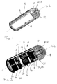
- An intracorporeal probe is shown in a perspective illustration in figure 1 and marked with the reference numeral 10.
- This probe 10 is used, for example, to examine hollow organs or body cavities in the human or animal body.
- the probe is used to examine the gastrointestinal tract of a patient.
- the probe 10 is swallowed for this purpose by the patient to be examined and thereafter travels through the gastrointestinal tract, finally being excreted again.
- the probe 10 is of elongated shape, the longitudinal axis being indicated by dashes in figure 1 , and being denoted by the letter L.
- the dimensions of the probe are selected such that the probe can be easily swallowed, and so they correspond approximately to the dimensions of conventional drug capsules.
- the probe 10 has a dome-shaped longitudinal end 12 that is fabricated from an optically transparent material.
- the remaining part of the probe which is denoted by the reference numeral 14, is fabricated from a nontransparent material.
- the longitudinal end 12 and the longitudinal section 14 adjoining it together form a liquid-tight and acid-resistant housing 16.
- an optics 18 Visible in the region of the longitudinal end 12 behind the transparent dome is an optics 18 whose optical axis coincides in figure 1 with the longitudinal axis L.
- the optics 18 serves the purpose of focusing light from outside the probe onto an image sensor.
- illumination elements 20 Provided in a fashion uniformly spaced around the optics 18 are illumination elements 20, the illumination elements 20 preferably being designed as LEDs 21.
- the LEDs 21 serve the purpose of illuminating a specific region outside the probe.
- the alignment of the LEDs 21 thus corresponds in essence to the alignment of the optics 18.
- the components provided inside the housing 16 are well in evidence in the illustration of figure 2 .
- an image sensor 22 that is preferably designed as a CMOS sensor 23.
- the image sensor 22 is seated, in turn, on a camera chip 24 that contains the logic circuitry required for evaluating the image signals supplied by the CMOS sensor.
- the optics 18, the image sensor 22 and the camera chip 24 together form an image pickup unit 26.
- the aforesaid elements 18, 22 and 24 are consequently permanently interconnected and therefore can be handled as a unit.
- the camera chip 24 is connected inside the housing to two points thereof, one connecting point being visible in figure 2 and denoted by the reference numeral 28.
- the other connecting point (not visible) lies on an axis that goes through the connecting point 28 and cuts the longitudinal axis L.
- the connecting points 28 are designed such that a rotation of the camera chip 24 about a transverse axis Q (that is perpendicular to the longitudinal axis L and goes through the two connecting points 28) can be performed.
- the entire image pickup unit 26, that is to say also the image sensor 22 and the optics 18, can be pivoted or swiveled about the transverse axis Q with the aid of this swiveling suspension of the camera chip 24.
- the consequence of such a swiveling movement is a variation of the optical axis by comparison with the longitudinal axis L, and thus a variation in the pickup region sensed by the image pickup unit 26.
- the image pickup unit 26 is designed to sense a specific pickup region outside the probe, and supply the optical images of the pickup region to the examining doctor.
- the motor 30 is a rotary motor, for example in the form of a Q-PEM motor, a time motor or a piezomotor.
- the motor 30 and the coupling element 32 together have the task of swiveling the camera chip 24, and thereby the image pickup unit 26 about the transverse axis Q.
- the rotary movement of the motor 30 is transformed via the coupling element 32 into a transverse movement.
- the coupling element 32 can be designed, for example, as a flexible shaft that is displaced in the longitudinal direction via a cam on the motor 30.
- a locating chip 34 that can supply exact position information.
- a locating chip is described in detail as a position-detecting element for example in the application WO 03/024328 of the applicant, and so reference is made for the purpose of simplification to this printed publication.
- the position-detecting means of the probe 10 can be designed, for example, as a coil system whose position can be detected via an external magnetic field detector.
- an energy and data transmission chip 36 that is responsible, on the one hand, for transmitting information from intracorporeal to extracorporeal space and, on the other hand, for receiving data, for example control signals, from extracorporeal space.
- data for example control signals
- the chip is capable of receiving energy from extracorporeal space.
- the probe 10 includes at least one battery 40 at the longitudinal end 38 opposite the longitudinal end 12.
- This battery 40 is designed such that it can supply sufficient energy to the aforementioned electronic components inside the probe 10.
- the probe 10 usually contains additional coils that are not shown in the figures. These coils can be used to position the probe in the gastrointestinal tract by applying an appropriate magnetic field extracorporeally. The examining doctor can therefore control the position of the probe from outside.
- the intracorporeal probe shown in figure 2 provides the examining doctor with a tool with the aid of which he obtains pictures of the gastrointestinal tract that are much more precisely targeted than has been possible to date using rigid image pickup units and position control solely by magnetic fields.
- a field of view of virtually 180° can be covered by swiveling the image pickup unit 26.
- the optics 18 can have an objective that is focusable and/or zoomable or can be switched to macrophotography.
- the focus can be set, for example, via a magnetic drive (not illustrated in figure 2 , however).
- the aforesaid preferred embodiment is of particular importance whenever the distance of the optics 18 from the inside of the dome-shaped longitudinal end 12 changes as a result of the swiveling movement of the image pickup unit.
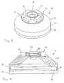
- Figures 3 and 4 show an image pickup unit 26 that differs somewhat with regard to its shape from the image pickup unit illustrated in figure 2 .
- the image pickup unit 26 comprises the camera chip 24, which has electronic components for processing image signals.
- the image sensor 22 lies inside an interior 42 that is surrounded by a housing 44.
- the housing 44 is fabricated from an opaque material such that light can pass into the interior 42 only through an opening 46. Starting from the opening 46, the interior 42 expands conically toward the image sensor 22.
- the upper longitudinal section 48 of the housing 44 also has this conical shape.
- the conical shape of the longitudinal section 48 enables a more effective possibility of swiveling inside the dome-shaped longitudinal end 12 of the probe 10.
- the optics 18, which preferably includes a focusing objective, is provided in the opening 46.
- the optics 18 is designed such that a region lying directly before the dome-shaped longitudinal end is focused onto the image sensor 22.
- the LEDs 21 are arranged adjacent to the optics 18, use being made of a total of four LEDs in the present exemplary embodiment. Of course, a different number of LEDs is also possible.
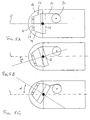
- the image pickup unit 26 is shown in figure 5A in its fundamental position, in which the optical axis, denoted by O, coincides with the longitudinal axis L of the probe 10.
- the motor 30 must be activated if the image pickup unit 26 is to be swiveled about the transverse axis Q.
- a stepwise rotation of the motor 30 leads to a displacement of the coupling element 32 and, owing to the fact that it is fitted offset from the transverse axis Q, to a swiveling of the image pickup unit 26.
- the image pickup unit 26 is swiveled counterclockwise by an angle ⁇ , while in figure 5C the swiveling has been performed in a clockwise fashion by the angle ⁇ .
- the two maximum values of the angles ⁇ are preferably designed such that a pickup region of virtually 180° can be detected by the image pickup unit.
- the person skilled in the art is familiar with different solutions of achieving the above-described swivelability of the image pickup unit 26 about the transverse axis Q.
- the invention is not intended to be limited to the illustrated solution with a rotary motor and a shaft as coupling element.
- control the motor 30 via control signals that are output by the examining doctor.
- Control signals can be received by the data transmission chip 36 and be processed to form control signals for the motor 30.
- the images supplied by the image pickup unit 26, preferably ten images per second, are processed by the logic circuitry on the camera chip 24, in particular compressed in order then to be transferred to extracorporeal space for the purpose of visualization for the examining doctor.
- the processing of the image signals on the camera chip 24 can be taken over, for example, by an ASIC designed therefor.
- the image information supplied to the examining doctor is linked to positional information that is supplied by the locating chip 34.
- the examining doctor therefore has the possibility of assigning the image information obtained to a specific region, for example inside the gastrointestinal tract.
- the energy required to supply the electronic components inside the probe 10 is supplied by the battery 40. However, it is also conceivable for the energy, or at least a portion of the required energy, to be fed from outside.
- the energy and data transmission chip 36 can have three orthogonal coils and a stack of thick film substrates that fix and connect the receiver's electronic components. The three coils can be pushed into one another in order to form a compact cylinder that surrounds the electronic components. Because of the orthogonality of the coils, at least always one coil is capable of extracting energy from the external magnetic field independently of the position and alignment of the probe.
- the probe of figure 2 is shown once again in another illustration in figures 6 and 7 . Identical components are marked with identical reference numerals for the sake of simplicity. It is clearly to be seen from the two figures 6 and 7 that the camera chip 24, and thus the image pickup unit 26 overall, is rotatably fitted on the housing 16 via two connecting points 28. Also to be seen are the cable connections 50 that run from the data transmission chip 36 to the camera chip 24 and the motor 30. Also well in evidence is the dome-shaped longitudinal end 12 that is fabricated from a transparent material, preferably glass.
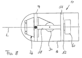
- an embodiment of the inventive intracorporeal probe 10 will now be described that differs from the previous probe only in that the image pickup unit 26 is also held in a fashion capable of rotating about the longitudinal axis L.
- the motor 30 and image pickup unit 26 are held by a frame 52 that can rotate inside the housing 16 about the longitudinal axis L.
- the frame 52 could comprise two rings 54, 56 that are supported on the inside of the housing.
- the two rings 54, 56 are interconnected via one or more elements 58 running in the longitudinal direction.
- the motor 30 is fastened on such a longitudinally running element 58 (longitudinal carrier) in the example shown in figure 8 .
- the rotation of the frame 52, and thus of the image pickup unit 26, about the longitudinal axis L is performed via a second motor 60, which is permanently connected to the housing 16 and, for example, cooperates with the ring 56 in order to rotate the frame 52.
- a second motor 60 which is permanently connected to the housing 16 and, for example, cooperates with the ring 56 in order to rotate the frame 52.
- other technical solutions can also be presented for the purpose, on the one hand, of holding the image pickup unit 26 and the motor 30 in a fashion capable of rotating about the longitudinal axis L, and, on the other hand, of undertaking the drive.
- the rotatability of the image pickup unit 26 about the longitudinal axis L expands the possible pickup region in such a way that virtually the entire region about the dome-shaped longitudinal end 12 can be detected.
- the motor 60 is preferably controlled via control signals output from extracorporeal space.
- the motor 60 could also be controlled via a permanently prescribed program.
- a single image pickup unit 26 is provided in the probe 10 in the previously described exemplary embodiments. However, it is also conceivable to provide the image pickup unit 26 additionally at the opposite longitudinal end such that the pickup region is much enlarged.
- the inventive intracorporeal probe could also be combined with a probe such as is disclosed in the printed publication WO 03/024328 already previously mentioned.
Landscapes
- Health & Medical Sciences (AREA)
- Life Sciences & Earth Sciences (AREA)
- Surgery (AREA)
- Nuclear Medicine, Radiotherapy & Molecular Imaging (AREA)
- Biomedical Technology (AREA)
- Optics & Photonics (AREA)
- Pathology (AREA)
- Radiology & Medical Imaging (AREA)
- Biophysics (AREA)
- Engineering & Computer Science (AREA)
- Physics & Mathematics (AREA)
- Heart & Thoracic Surgery (AREA)
- Medical Informatics (AREA)
- Molecular Biology (AREA)
- Animal Behavior & Ethology (AREA)
- General Health & Medical Sciences (AREA)
- Public Health (AREA)
- Veterinary Medicine (AREA)
- Endoscopes (AREA)
Description
- The present invention relates to an intracorporeal probe, for example preferably for examining hollow organs or natural or artificially created body cavities in the human or animal body, the probe being designed in the form of a capsule that can be introduced into the body without external connecting elements, comprising a housing having an elongated shape and an image pickup unit inside the housing that is designed for optically recording, for example imaging, a region (termed pickup region below) outside the probe, the image picKup unit being held in a fashion capable of moving inside the housing in order to vary the picKup region by means of such a movement.
- An intracorporeal probe of the aforesaid type is known in general, for example from
US 2005/0043583 A1 orDE 101 46 197 .EP-A-0 667 115 also discloses an intracorporeal probe that is designed in the form of a capsule that can be swallowed by the patient to be examined in order to be able to examine the gastrointestinal tract visually. The optical signals received from the probe are transmitted telemetrically via a transmitter present in the capsule to extracorporeal space and visualized there. This known autonomous video probe certainly enables visual inspection of the gastrointestinal tract, and permits the images to be transmitted to the outside telemetrically, but undertaking a diagnosis with the aid of the transmitted images is exceptionally difficult. The reason for this resides in the fact that, although the position of the probe inside the patient can be determined in the meantime relatively well, the regions picked up by the image sensor installed in the probe are of a rather random nature. It is not possible for specific regions inside the gastrointestinal tract to be specifically picked up. The image information obtained by the probe is consequently more of a random product and cannot be determined by the examining doctor. - Against this background, the invention is therefore based on the object of developing the intracorporeal probe mentioned at the beginning so as to enable a controlled, flexible and targeted visualization.
- According to the invention, this object is achieved with regard to the intracorporeal probe mentioned at the beginning by virtue of the fact that the image pickup unit is held in a fashion capable of swiveling about an axis that runs perpendicular to the longitudinal axis of the probe and capable of rotating about the longitudinal axis of the probe.
- That is to say, in other words, the alignment of the image pickup unit can be varied such that the straight ahead front view of previous probe solutions can be varied via an appropriate movement of the image pickup unit to provide a side view as well, without there being variation in the position of the probe itself. Overall, it is thereby possible for the field of view of the image pickup unit to be greatly enlarged by varying its position inside the probe.
- The examining doctor obtains much more image information with the aid of the inventive probe while the probe is passing through the gastrointestinal tract.
- The aforesaid measures have proved to be particularly advantageous in practice. In particular, a very large pickup region is permitted by the ability of the image pickup unit to swivel about an axis that runs perpendicular to the longitudinal axis of the probe.
- This measure has the advantage that the pickup region can be greatly enlarged once more. By swiveling the image pickup unit about the transverse axis, and by rotation about the longitudinal axis it is possible to bring the image pickup unit into many more positions such that the pickup region can pick up at least a hemispherical region around the probe.
- In a preferred refinement, the image pickup unit has an image sensor and a pickup optics. The image pickup unit preferably has at least one illumination element for illuminating the pickup region.
- The aforementioned measures have the advantage that a very compact image pickup unit is provided that owing to its movable mounting inside the housing of the probe moves the image sensor and pickup optics together. It is thereby possible to achieve a simpler control for the execution of a movement, since only one component need be moved.
- The fact that the image pickup unit also has an illumination element, which means at the same time that the illumination element cooperates in the movement of the image sensor and the pickup optics, enables optimum illumination of the corresponding pickup region. The illumination element always illuminates the selected pickup region without requiring a dedicated control.
- It is preferred to provide a first motor that is coupled to the image pickup unit in order to move the latter. The motor is preferably a wobble motor, in particular a Q-PEM motor.
- The pickup region itself, that is to say the position of the image pickup unit, can be set via the first motor, preferably via control signals output by the examining doctor. Of course, it is also conceivable to control the motor in accordance with a permanently prescribed program without external influence.
- The use of a wobble motor has proved to be advantageous as regards the aspects of energy and accuracy in particular. A wobble motor requires little energy and can be moved in very precise small incremental steps.
- In a further preferred refinement, a coupling element is provided between the motor and image pickup unit and is designed to convert a rotary movement of the motor into a transverse movement. The coupling element is preferably fitted on the image pickup unit in a fashion remote from the swiveling axis, and the coupling element preferably comprises a flexible shaft.
- These measures permit a very efficient swiveling of the image pickup unit about the axis perpendicular to the longitudinal axis. The flexible shaft in this case undertakes the swiveling of the image pickup unit when the motor rotates.
- It goes without saying that the previously described approach to a solution for swiveling the image pickup unit about the transverse axis (with reference to the longitudinal axis of the probe) is a purely exemplary one. The person skilled in the art will recognize that other possibilities exist for appropriately coupling the image pickup unit to a motor in order to achieve a swiveling movement about the transverse axis. Thus, for example, the coupling of a motor to the image pickup unit could be performed via the transverse axis, that is to say the transverse axis or a corresponding transversely running shaft transmits the rotary movement of the motor to the image pickup unit.
- A second motor is preferably provided in order to rotate the image pickup unit about the probe longitudinal axis. With particular preference, the image pickup unit and the first motor are interconnected with the aid of the coupling element in order to be able to rotate jointly about the probe longitudinal axis.
- In a further embodiment, a mounting frame that carries the image pickup unit and the first motor is provided in the housing, and is preferably coupled to the second motor for rotation about the probe longitudinal axis.
- This is a conceivable solution for holding the image pickup unit and the two motors inside the probe. However, it will be clear to the person skilled in the art that there are further possible ways of holding the image pickup unit, the first motor and the second motor appropriately in the housing of the probe so as to ensure fluidity of swiveling about the transverse axis, and of rotating about the longitudinal axis.
- In a further preferred embodiment, the image sensor is a CMOS image sensor, for example an HDRC (high dynamic range camera) type CMOS image sensor, preferably with a resolution of 768 x 496 pixels. The CMOS image sensor is preferably operated at an imaging rate of at least two, in particular ten, more preferably at least twenty images per second.
-
- In a further preferred refinement, the probe has a transmitting unit for transmitting the acquired images from intracorporeal space to extracorporeal space, an energy receiving and supply unit that preferably receives energy inductively from extracorporeal space and supplies units inside the probe with energy, and a locating unit for locating the intracorporeal position of the probe from the extracorporeal.
- The energy receiving and supply unit can be used to transfer into the probe energy from extracorporeal space that then serves to supply the respective elements, in particular the image pickup unit and the motors. The locating unit can be used for accurate determination of the position of the probe inside the gastrointestinal tract of the patient, the alignment or position of the longitudinal axis of the probe relating to this purpose, as well. These data enable the examining doctor on the one hand to be able to classify and evaluate the received images more effectively and, on the other hand, to have the motors controlled in a targeted fashion and thus to vary the pickup region.
- It is thereby possible to pick up specific pickup regions deliberately such that the pictures of the gastrointestinal tract that are supplied are no longer random products. Consequently, the results of diagnosis can be much improved overall.
- It may be remarked at this juncture that the aforesaid units, specifically transmitting unit, energy receiving and supply unit and locating unit can also be used separately of one another.
- In a further preferred embodiment, the illumination element is a light-emitting diode. It is preferred to provide a number of light-emitting diodes that are arranged around the optics for uniform illumination of the pickup region.
- On the one hand, light-emitting diodes are very compact components, while on the other hand they manage with relatively little energy in conjunction with a high light yield, something which renders them advantageous for use in an intracorporeal probe.
- In a further preferred embodiment, an electroacoustic transducer is provided that generates an acoustic signal in the audible or in the ultrasonic range.
- It is further preferred that in addition to the image sensor the image pickup unit has further electronic elements for processing the signals supplied by the image sensor.
- This measure has the advantage that the image signals can be compressed, for example, even in the probe in order thereby to be able to lower the requisite data transmission rate or, vice versa, to be able to transmit more image data to extracorporeal space per time unit.
- In a further preferred embodiment, the image pickup unit is arranged at a longitudinal end of the housing, and this end region of the housing is of dome-shaped and transparent design.
- The arrangement of the image pickup unit at a longitudinal end has proved to be particularly advantageous with regard to the possible pickup region. However, it is to be remarked that the image pickup unit could also be arranged at other positions inside the probe. Moreover, it is conceivable that at least one further image pickup unit is provided in a movable fashion, for example in such a way that their pickup regions complement one another. For example, the image pickup units could be arranged such that - in the unswiveled state - their optical axes are perpendicular to one another.
- This preferred refinement enables a further enlargement of the pickup region, and thus an improvement in the results of diagnosis, since more image information, for example from the gastrointestinal tract, is available to the examining doctor.
- Further advantages and features emerge from the following description and the attached drawing. It goes without saying that the aforementioned features, and those still to be explained below, can be used not only in the respectively specified combination, but also in other combinations or on their own without departing from the scope of the present invention.
- Exemplary embodiments of the invention are illustrated in the drawing and will be described in more detail hereinafter with reference thereto, wherein:
- figure 1
- shows a perspective view of an intracorporeal probe ;
- figure 2
- shows a perspective illustration of the probe from
figure 1 with partially opened housing; - figure 3
- shows a perspective schematic diagram of an image pickup unit;
- figure 4
- shows a sectional schematic diagram of the image pickup unit from
figure 3 ; - figures 5A-C
- show a schematic diagram of the image pickup unit inside the probe for the purpose of explaining the inventive mobility of the image pickup unit;
- figure 6
- shows an exploded schematic diagram of the probe;
- figure 7
- shows a perspective schematic diagram of a longitudinal section of the probe that contains the image pickup unit; and
- figure 8
- shows a schematic diagram of a further inventive embodiment of the intracorporeal probe for the purpose of achieving the ability to rotate about the longitudinal axis.
- An intracorporeal probe is shown in a perspective illustration in
figure 1 and marked with thereference numeral 10. Thisprobe 10 is used, for example, to examine hollow organs or body cavities in the human or animal body. In particular, the probe is used to examine the gastrointestinal tract of a patient. Theprobe 10 is swallowed for this purpose by the patient to be examined and thereafter travels through the gastrointestinal tract, finally being excreted again. - The
probe 10 is of elongated shape, the longitudinal axis being indicated by dashes infigure 1 , and being denoted by the letter L. The dimensions of the probe are selected such that the probe can be easily swallowed, and so they correspond approximately to the dimensions of conventional drug capsules. - The
probe 10 has a dome-shapedlongitudinal end 12 that is fabricated from an optically transparent material. By contrast therewith, the remaining part of the probe, which is denoted by thereference numeral 14, is fabricated from a nontransparent material. Thelongitudinal end 12 and thelongitudinal section 14 adjoining it together form a liquid-tight and acid-resistant housing 16. - Visible in the region of the
longitudinal end 12 behind the transparent dome is anoptics 18 whose optical axis coincides infigure 1 with the longitudinal axis L. Theoptics 18 serves the purpose of focusing light from outside the probe onto an image sensor. - Provided in a fashion uniformly spaced around the
optics 18 are illumination elements 20, the illumination elements 20 preferably being designed asLEDs 21. TheLEDs 21 serve the purpose of illuminating a specific region outside the probe. The alignment of theLEDs 21 thus corresponds in essence to the alignment of theoptics 18. - The components provided inside the
housing 16 are well in evidence in the illustration offigure 2 . Following theoptics 18 is animage sensor 22 that is preferably designed as a CMOS sensor 23. Theimage sensor 22 is seated, in turn, on acamera chip 24 that contains the logic circuitry required for evaluating the image signals supplied by the CMOS sensor. - The
optics 18, theimage sensor 22 and thecamera chip 24 together form animage pickup unit 26. Theaforesaid elements camera chip 24 is connected inside the housing to two points thereof, one connecting point being visible infigure 2 and denoted by thereference numeral 28. The other connecting point (not visible) lies on an axis that goes through the connectingpoint 28 and cuts the longitudinal axis L. The connecting points 28 are designed such that a rotation of thecamera chip 24 about a transverse axis Q (that is perpendicular to the longitudinal axis L and goes through the two connecting points 28) can be performed. - The entire
image pickup unit 26, that is to say also theimage sensor 22 and theoptics 18, can be pivoted or swiveled about the transverse axis Q with the aid of this swiveling suspension of thecamera chip 24. The consequence of such a swiveling movement is a variation of the optical axis by comparison with the longitudinal axis L, and thus a variation in the pickup region sensed by theimage pickup unit 26. - Overall, the
image pickup unit 26 is designed to sense a specific pickup region outside the probe, and supply the optical images of the pickup region to the examining doctor. - Following the
image pickup unit 26 inside theprobe 10, as seen in the longitudinal direction, is apositioning motor 30 that is connected to thecamera chip 24 via acoupling element 32. Themotor 30 is a rotary motor, for example in the form of a Q-PEM motor, a time motor or a piezomotor. Themotor 30 and thecoupling element 32 together have the task of swiveling thecamera chip 24, and thereby theimage pickup unit 26 about the transverse axis Q. In the present exemplary embodiment, the rotary movement of themotor 30 is transformed via thecoupling element 32 into a transverse movement. Thecoupling element 32 can be designed, for example, as a flexible shaft that is displaced in the longitudinal direction via a cam on themotor 30. - Of course, the person skilled in the art is also familiar with other solutions that enable a swiveling movement of the
image pickup unit 26. For example, instead of therotary motor 30 it would be possible to use a linear motor for swiveling theimage pickup unit 26. - Provided in the same longitudinal section as the
motor 30 inside thehousing 16 of theprobe 10 is alocating chip 34 that can supply exact position information. A locating chip is described in detail as a position-detecting element for example in the applicationWO 03/024328 probe 10 can be designed, for example, as a coil system whose position can be detected via an external magnetic field detector. - Other solutions directed to locating, that is to say determining the position of the probe, for example inside the gastrointestinal tract, are, of course, also conceivable.
- Following the
locating chip 34 in the longitudinal direction is an energy anddata transmission chip 36 that is responsible, on the one hand, for transmitting information from intracorporeal to extracorporeal space and, on the other hand, for receiving data, for example control signals, from extracorporeal space. Corresponding solutions for the transmission of such data are likewise described in the previously mentioned printed publicationWO 03/024328 - Finally, the
probe 10 includes at least onebattery 40 at thelongitudinal end 38 opposite thelongitudinal end 12. Thisbattery 40 is designed such that it can supply sufficient energy to the aforementioned electronic components inside theprobe 10. - The
probe 10 usually contains additional coils that are not shown in the figures. These coils can be used to position the probe in the gastrointestinal tract by applying an appropriate magnetic field extracorporeally. The examining doctor can therefore control the position of the probe from outside. - All in all, the intracorporeal probe shown in
figure 2 provides the examining doctor with a tool with the aid of which he obtains pictures of the gastrointestinal tract that are much more precisely targeted than has been possible to date using rigid image pickup units and position control solely by magnetic fields. A field of view of virtually 180° can be covered by swiveling theimage pickup unit 26. In order further to improve the image quality, theoptics 18 can have an objective that is focusable and/or zoomable or can be switched to macrophotography. The focus can be set, for example, via a magnetic drive (not illustrated infigure 2 , however). The aforesaid preferred embodiment is of particular importance whenever the distance of theoptics 18 from the inside of the dome-shapedlongitudinal end 12 changes as a result of the swiveling movement of the image pickup unit. - Of course, other image sensors, for example CCD sensors, are also conceivable in addition to the abovementioned CMOS sensor 23. However, an HDRC (High Dynamic Range Camera) image sensor based on CMOS technology has proved to be particularly advantageous in practice. Such a logarithmically operating sensor is described in detail in
DE 42 09 536 -
Figures 3 and 4 show animage pickup unit 26 that differs somewhat with regard to its shape from the image pickup unit illustrated infigure 2 . - As already mentioned, the
image pickup unit 26 comprises thecamera chip 24, which has electronic components for processing image signals. On thiscamera chip 24, theimage sensor 22 lies inside an interior 42 that is surrounded by ahousing 44. Thehousing 44 is fabricated from an opaque material such that light can pass into the interior 42 only through anopening 46. Starting from theopening 46, the interior 42 expands conically toward theimage sensor 22. - The upper
longitudinal section 48 of thehousing 44 also has this conical shape. The conical shape of thelongitudinal section 48 enables a more effective possibility of swiveling inside the dome-shapedlongitudinal end 12 of theprobe 10. - The
optics 18, which preferably includes a focusing objective, is provided in theopening 46. - The
optics 18 is designed such that a region lying directly before the dome-shaped longitudinal end is focused onto theimage sensor 22. - The
LEDs 21 are arranged adjacent to theoptics 18, use being made of a total of four LEDs in the present exemplary embodiment. Of course, a different number of LEDs is also possible. - The swivelability of the
image pickup unit 26 will now be examined again with reference tofigures 5A-C . - The
image pickup unit 26 is shown infigure 5A in its fundamental position, in which the optical axis, denoted by O, coincides with the longitudinal axis L of theprobe 10. - The
motor 30 must be activated if theimage pickup unit 26 is to be swiveled about the transverse axis Q. A stepwise rotation of themotor 30 leads to a displacement of thecoupling element 32 and, owing to the fact that it is fitted offset from the transverse axis Q, to a swiveling of theimage pickup unit 26. Infigure 5B , theimage pickup unit 26 is swiveled counterclockwise by an angle α, while infigure 5C the swiveling has been performed in a clockwise fashion by the angle α. The two maximum values of the angles α are preferably designed such that a pickup region of virtually 180° can be detected by the image pickup unit. - As already mentioned, the person skilled in the art is familiar with different solutions of achieving the above-described swivelability of the
image pickup unit 26 about the transverse axis Q. The invention is not intended to be limited to the illustrated solution with a rotary motor and a shaft as coupling element. - In order to achieve swiveling of the
image pickup unit 26, it is preferred to control themotor 30 via control signals that are output by the examining doctor. Control signals can be received by thedata transmission chip 36 and be processed to form control signals for themotor 30. Of course, it is also conceivable to run the swiveling of theimage pickup unit 26 via a permanently prescribed control program stored in the electronics of theprobe 10. - The images supplied by the
image pickup unit 26, preferably ten images per second, are processed by the logic circuitry on thecamera chip 24, in particular compressed in order then to be transferred to extracorporeal space for the purpose of visualization for the examining doctor. The processing of the image signals on thecamera chip 24 can be taken over, for example, by an ASIC designed therefor. - The image information supplied to the examining doctor is linked to positional information that is supplied by the locating
chip 34. The examining doctor therefore has the possibility of assigning the image information obtained to a specific region, for example inside the gastrointestinal tract. - The energy required to supply the electronic components inside the
probe 10 is supplied by thebattery 40. However, it is also conceivable for the energy, or at least a portion of the required energy, to be fed from outside. To this end, the energy anddata transmission chip 36 can have three orthogonal coils and a stack of thick film substrates that fix and connect the receiver's electronic components. The three coils can be pushed into one another in order to form a compact cylinder that surrounds the electronic components. Because of the orthogonality of the coils, at least always one coil is capable of extracting energy from the external magnetic field independently of the position and alignment of the probe. - The probe of
figure 2 is shown once again in another illustration infigures 6 and 7 . Identical components are marked with identical reference numerals for the sake of simplicity. It is clearly to be seen from the twofigures 6 and 7 that thecamera chip 24, and thus theimage pickup unit 26 overall, is rotatably fitted on thehousing 16 via two connectingpoints 28. Also to be seen are the cable connections 50 that run from thedata transmission chip 36 to thecamera chip 24 and themotor 30. Also well in evidence is the dome-shapedlongitudinal end 12 that is fabricated from a transparent material, preferably glass. - With reference to
figure 8 , an embodiment of the inventiveintracorporeal probe 10 will now be described that differs from the previous probe only in that theimage pickup unit 26 is also held in a fashion capable of rotating about the longitudinal axis L. - To this end, the
motor 30 andimage pickup unit 26 are held by aframe 52 that can rotate inside thehousing 16 about the longitudinal axis L. For example, theframe 52 could comprise tworings 54, 56 that are supported on the inside of the housing. The two rings 54, 56 are interconnected via one ormore elements 58 running in the longitudinal direction. Themotor 30 is fastened on such a longitudinally running element 58 (longitudinal carrier) in the example shown infigure 8 . - The rotation of the
frame 52, and thus of theimage pickup unit 26, about the longitudinal axis L is performed via asecond motor 60, which is permanently connected to thehousing 16 and, for example, cooperates with thering 56 in order to rotate theframe 52. Of course, other technical solutions can also be presented for the purpose, on the one hand, of holding theimage pickup unit 26 and themotor 30 in a fashion capable of rotating about the longitudinal axis L, and, on the other hand, of undertaking the drive. - The rotatability of the
image pickup unit 26 about the longitudinal axis L expands the possible pickup region in such a way that virtually the entire region about the dome-shapedlongitudinal end 12 can be detected. - As also in the case of the
motor 30, themotor 60 is preferably controlled via control signals output from extracorporeal space. However, themotor 60 could also be controlled via a permanently prescribed program. - A single
image pickup unit 26 is provided in theprobe 10 in the previously described exemplary embodiments. However, it is also conceivable to provide theimage pickup unit 26 additionally at the opposite longitudinal end such that the pickup region is much enlarged. - Finally, it is also conceivable to provide two swiveling
image pickup units 26 at a longitudinal end of theprobe 10, or to provide an image pickup unit whose optical axis runs perpendicular to the longitudinal axis L and permits visual detection of the region at thelateral housing 16. - The inventive intracorporeal probe could also be combined with a probe such as is disclosed in the printed publication
WO 03/024328 - It may be stated in summary that a substantial improvement is possible, in particular with regard to the targeting accuracy of the imaging, with the aid of the inventive swiveling arrangement of the
image pickup unit 26.
Claims (23)
- An intracorporeal probe, for example preferably for examining hollow organs or natural or artificially created body cavities in the human or animal body, the probe (10) being designed in the form of a capsule configured to be introduced into the body without external connecting elements, comprising- a housing (16) having an elongated shape; and- an image pickup unit (26) inside the housing (16) that is configured to optically record a region (pickup region) outside the probe (10), the image pickup unit (26) being held in a fashion capable of moving inside the housing in order to vary the pickup region by means of such a movement;characterised in that
the image pickup unit (26) is held in a fashion capable of swiveling about an axis (O) that runs perpendicular to the longitudinal axis (L) of the probe (10) and capable of rotating about the longitudinal axis (L) of the probe (10). - The probe as claimed in claim 1, wherein the image pickup unit (26) has an image sensor (22) and a pickup optics (18).
- The probe as claimed in claim 1 or 2, wherein the image pickup unit (26) has at least one illumination element (20) for illuminating the pickup region.
- The probe as claimed in one of the preceding claims, wherein a first motor (30) is provided that is coupled to the image pickup unit (26) in order to move the latter.
- The probe as claimed in claim 4, wherein the motor (30) is a wobble motor, in particular a Q-PEM motor.
- The probe as claimed in claim 4 or 5, wherein a coupling element (32) is provided between the motor (30) and image pickup unit (26) and is designed to convert a rotary movement of the motor (30) into a transverse movement.
- The probe as claimed in claim 6, wherein the coupling element (32) is fitted on the image pickup unit (26) in a fashion remote from the swiveling axis.
- The probe as claimed in claim 7, wherein the coupling element (32) comprises a flexible shaft.
- The probe as claimed in any of claims 4 - 9, wherein a second motor is provided in order to rotate the image pickup unit (26) about the probe longitudinal axis (L).
- The probe as claimed in claim 9, wherein the image pickup unit (26) and first motor (30) are interconnected with the aid of the coupling element (32) in order to be able to rotate jointly about the probe longitudinal axis (L).
- The probe as claimed in claim 10, wherein a mounting frame that carries the image pickup unit (26) and first motor (30) is provided in the housing (16).
- The probe as claimed in claim 11, wherein the mounting frame is coupled to the second motor for rotation about the probe longitudinal axis (L).
- The probe as claimed in claim 2, wherein the image sensor (22) is a CMOS image sensor, preferably an HDRC (high dynamic range camera) type CMOS image sensor, preferably with a resolution of 768 x 496 pixels.
- The probe as claimed in claim 13, wherein the CMOS image sensor (22) is operated at an imaging rate of at least two, preferably at least twenty images per second.
- The probe as claimed in one of the preceding claims, defined by- a transmitting unit (36) for transmitting the acquired images from intracorporeal space to extracorporeal space;- an energy receiving and supply unit (36) that preferably receives energy inductively from extracorporeal space and supplies units inside the probe (10) with energy, and- a locating unit (34) for locating the intracorporeal position of the probe from the extracorporeal.
- The probe as claimed in claim 3, wherein the illumination element (20) is a light-emitting diode (21).
- The probe as claimed in claim 16, wherein a number of light-emitting diodes (21) are provided that are arranged around the optics (18) for uniform illumination of the pickup region.
- The probe as claimed in one of the preceding claims, wherein an electroacoustic transducer is provided that is being configured to generate an acoustic signal in the audible or in the ultrasonic range.
- The probe as claimed in one of the claims 2, 13 or 14 wherein in addition to the image sensor (22) the image pickup unit (26) has further electronic elements for processing the signals supplied by the image sensor (22).
- The probe as claimed in one of the preceding claims, wherein the image pickup unit (26) is arranged at a longitudinal end (12) of the housing (16), and this end region of the housing (16) is of dome-shaped and transparent design.
- The probe as claimed in one of the preceding claims, wherein at least one further image pickup unit (26) is provided in a movable fashion.
- The probe as claimed in claim 21, wherein the further image pickup unit (26) is arranged such that their pickup regions complement one another.
- The probe as claimed in claims 20 and 21, wherein the further image pickup unit (26) is arranged at the opposite longitudinal end (38) of the housing (16).
Applications Claiming Priority (2)
| Application Number | Priority Date | Filing Date | Title |
|---|---|---|---|
| DE200510015522 DE102005015522A1 (en) | 2005-04-04 | 2005-04-04 | Intracorporal probe for human or animal body, has image acquisition unit designed for optical admission of area outside probe, and movably held within housing in order to change movement of admission area |
| PCT/EP2006/003054 WO2006105932A1 (en) | 2005-04-04 | 2006-04-04 | Intracorporeal videocapsule with swiveling image pickup |
Publications (2)
| Publication Number | Publication Date |
|---|---|
| EP1868487A1 EP1868487A1 (en) | 2007-12-26 |
| EP1868487B1 true EP1868487B1 (en) | 2012-10-03 |
Family
ID=36616062
Family Applications (1)
| Application Number | Title | Priority Date | Filing Date |
|---|---|---|---|
| EP06724010A Ceased EP1868487B1 (en) | 2005-04-04 | 2006-04-04 | Intracorporeal videocapsule with swiveling and rotating image pickup |
Country Status (4)
| Country | Link |
|---|---|
| US (1) | US9028399B2 (en) |
| EP (1) | EP1868487B1 (en) |
| DE (1) | DE102005015522A1 (en) |
| WO (1) | WO2006105932A1 (en) |
Cited By (3)
| Publication number | Priority date | Publication date | Assignee | Title |
|---|---|---|---|---|
| US10172598B2 (en) | 2012-02-17 | 2019-01-08 | Progenity, Inc. | Ingestible medical device |
| DE102021133252A1 (en) | 2021-12-15 | 2023-06-15 | Karl Storz Se & Co. Kg | Endoscopic Capsule |
| DE102021133248A1 (en) | 2021-12-15 | 2023-06-15 | Karl Storz Se & Co. Kg | Endoscopy device and endoscopy system |
Families Citing this family (65)
| Publication number | Priority date | Publication date | Assignee | Title |
|---|---|---|---|---|
| US20090198099A1 (en) * | 2008-02-05 | 2009-08-06 | Myers Stephen R | In vivo imaging system |
| WO2009140641A2 (en) * | 2008-05-16 | 2009-11-19 | Fluid Medical, Inc. | Miniature forward-looking ultrasound imaging mechanism enabled by local shape memory alloy actuator |
| DE102008035092B4 (en) * | 2008-07-28 | 2015-08-27 | Siemens Aktiengesellschaft | Apparatus for performing a minimally invasive diagnosis or intervention in the interior of a patient with a capsule endoscope and method for determining the actual position of a capsule endoscope in the interior of a patient |
| US12137873B2 (en) | 2009-06-18 | 2024-11-12 | Endochoice, Inc. | Compact multi-viewing element endoscope system |
| US9642513B2 (en) | 2009-06-18 | 2017-05-09 | Endochoice Inc. | Compact multi-viewing element endoscope system |
| US11864734B2 (en) | 2009-06-18 | 2024-01-09 | Endochoice, Inc. | Multi-camera endoscope |
| US9872609B2 (en) | 2009-06-18 | 2018-01-23 | Endochoice Innovation Center Ltd. | Multi-camera endoscope |
| US9402533B2 (en) | 2011-03-07 | 2016-08-02 | Endochoice Innovation Center Ltd. | Endoscope circuit board assembly |
| US9901244B2 (en) | 2009-06-18 | 2018-02-27 | Endochoice, Inc. | Circuit board assembly of a multiple viewing elements endoscope |
| US9492063B2 (en) | 2009-06-18 | 2016-11-15 | Endochoice Innovation Center Ltd. | Multi-viewing element endoscope |
| US9706903B2 (en) | 2009-06-18 | 2017-07-18 | Endochoice, Inc. | Multiple viewing elements endoscope system with modular imaging units |
| US11278190B2 (en) | 2009-06-18 | 2022-03-22 | Endochoice, Inc. | Multi-viewing element endoscope |
| EP2865322B1 (en) | 2009-06-18 | 2020-07-22 | EndoChoice, Inc. | Multi-camera endoscope |
| WO2012077116A1 (en) | 2010-12-09 | 2012-06-14 | Peermedical Ltd. | Flexible electronic circuit board for a multi-camera endoscope |
| US9101268B2 (en) | 2009-06-18 | 2015-08-11 | Endochoice Innovation Center Ltd. | Multi-camera endoscope |
| US10165929B2 (en) | 2009-06-18 | 2019-01-01 | Endochoice, Inc. | Compact multi-viewing element endoscope system |
| US9101287B2 (en) | 2011-03-07 | 2015-08-11 | Endochoice Innovation Center Ltd. | Multi camera endoscope assembly having multiple working channels |
| US9713417B2 (en) | 2009-06-18 | 2017-07-25 | Endochoice, Inc. | Image capture assembly for use in a multi-viewing elements endoscope |
| US8926502B2 (en) | 2011-03-07 | 2015-01-06 | Endochoice, Inc. | Multi camera endoscope having a side service channel |
| US11547275B2 (en) | 2009-06-18 | 2023-01-10 | Endochoice, Inc. | Compact multi-viewing element endoscope system |
| US12220105B2 (en) | 2010-06-16 | 2025-02-11 | Endochoice, Inc. | Circuit board assembly of a multiple viewing elements endoscope |
| EP4233680B1 (en) | 2010-09-20 | 2025-06-18 | EndoChoice, Inc. | Endoscope distal section comprising a unitary fluid channeling component |
| US9560953B2 (en) | 2010-09-20 | 2017-02-07 | Endochoice, Inc. | Operational interface in a multi-viewing element endoscope |
| JP5944912B2 (en) | 2010-10-28 | 2016-07-05 | エンドチョイス イノベーション センター リミテッド | Optical system for multi-sensor endoscope |
| US12204087B2 (en) | 2010-10-28 | 2025-01-21 | Endochoice, Inc. | Optical systems for multi-sensor endoscopes |
| EP2648602B1 (en) | 2010-12-09 | 2018-07-18 | EndoChoice Innovation Center Ltd. | Flexible electronic circuit board multi-camera endoscope |
| US11889986B2 (en) | 2010-12-09 | 2024-02-06 | Endochoice, Inc. | Flexible electronic circuit board for a multi-camera endoscope |
| EP2672878B1 (en) | 2011-02-07 | 2017-11-22 | Endochoice Innovation Center Ltd. | Multi-element cover for a multi-camera endoscope |
| EP2701573B1 (en) * | 2011-04-26 | 2018-08-22 | Otto-von-Guericke Universität Magdeburg Medizinische Fakultät | Endoscope |
| WO2013055917A1 (en) * | 2011-10-12 | 2013-04-18 | Volcano Corporation | Rotational shape-memory actuators and associated devices, systems, and methods |
| US10029079B2 (en) | 2011-10-18 | 2018-07-24 | Treble Innovations | Endoscopic peripheral |
| US9757150B2 (en) | 2011-10-18 | 2017-09-12 | Treble Innovations | Portable endoscope and method of use thereof |
| EP2604175B1 (en) | 2011-12-13 | 2019-11-20 | EndoChoice Innovation Center Ltd. | Removable tip endoscope |
| CA2798729A1 (en) | 2011-12-13 | 2013-06-13 | Peermedical Ltd. | Rotatable connector for an endoscope |
| US10143358B2 (en) * | 2012-02-07 | 2018-12-04 | Treble Innovations, Llc | System and method for a magnetic endoscope |
| US9345393B2 (en) * | 2012-03-13 | 2016-05-24 | Panasonic Intellectual Property Management Co., Ltd. | Endoscope camera |
| US10022041B2 (en) | 2012-06-27 | 2018-07-17 | Camplex, Inc. | Hydraulic system for surgical applications |
| US9642606B2 (en) | 2012-06-27 | 2017-05-09 | Camplex, Inc. | Surgical visualization system |
| US9560954B2 (en) | 2012-07-24 | 2017-02-07 | Endochoice, Inc. | Connector for use with endoscope |
| DE102012017498A1 (en) * | 2012-09-05 | 2014-03-06 | Olympus Winter & Ibe Gmbh | casing |
| US9170590B2 (en) | 2012-10-31 | 2015-10-27 | Qualcomm Incorporated | Method and apparatus for load adaptive LDO bias and compensation |
| US9235225B2 (en) | 2012-11-06 | 2016-01-12 | Qualcomm Incorporated | Method and apparatus reduced switch-on rate low dropout regulator (LDO) bias and compensation |
| US8981745B2 (en) | 2012-11-18 | 2015-03-17 | Qualcomm Incorporated | Method and apparatus for bypass mode low dropout (LDO) regulator |
| US9986899B2 (en) | 2013-03-28 | 2018-06-05 | Endochoice, Inc. | Manifold for a multiple viewing elements endoscope |
| US9993142B2 (en) | 2013-03-28 | 2018-06-12 | Endochoice, Inc. | Fluid distribution device for a multiple viewing elements endoscope |
| US10499794B2 (en) | 2013-05-09 | 2019-12-10 | Endochoice, Inc. | Operational interface in a multi-viewing element endoscope |
| EP2999414B1 (en) | 2013-05-21 | 2018-08-08 | Camplex, Inc. | Surgical visualization systems |
| JP6521982B2 (en) | 2013-09-20 | 2019-05-29 | キャンプレックス インコーポレイテッド | Surgical visualization system and display |
| EP3046458B1 (en) | 2013-09-20 | 2020-10-21 | Camplex, Inc. | Surgical visualization systems |
| EP3226799A4 (en) | 2014-12-05 | 2018-07-25 | Camplex, Inc. | Surgical visualization systems and displays |
| US11154378B2 (en) | 2015-03-25 | 2021-10-26 | Camplex, Inc. | Surgical visualization systems and displays |
| JP6308440B2 (en) * | 2015-06-17 | 2018-04-11 | パナソニックIpマネジメント株式会社 | Endoscope |
| US10966798B2 (en) | 2015-11-25 | 2021-04-06 | Camplex, Inc. | Surgical visualization systems and displays |
| US10517470B2 (en) | 2016-05-13 | 2019-12-31 | Karl Storz Endovision, Inc. | Optical instrument and articulating image sensing apparatus therefor |
| JP2019530508A (en) * | 2016-09-29 | 2019-10-24 | 270 サージカル リミテッド | Rigid medical surgical lighting system |
| US10918455B2 (en) | 2017-05-08 | 2021-02-16 | Camplex, Inc. | Variable light source |
| USD918266S1 (en) * | 2018-07-11 | 2021-05-04 | Stephen Weil | Trolling motor cover |
| CN109044406B (en) * | 2018-09-14 | 2023-09-08 | 太原科技大学 | Ultrasonic capsule endoscope detection system with reciprocating scanning function |
| WO2020106757A1 (en) | 2018-11-19 | 2020-05-28 | Progenity, Inc. | Ingestible device for delivery of therapeutic agent to the gastrointestinal tract |
| CN110089991B (en) * | 2019-04-23 | 2021-07-23 | 南通市传染病防治院(南通市第三人民医院) | A kind of endoscopic positioning device and positioning method for the treatment of digestive tract lesions |
| DE102019003378A1 (en) | 2019-05-14 | 2020-11-19 | Karl Storz Se & Co. Kg | Observation instrument and video imager assembly for an observation instrument |
| DE102019130949A1 (en) * | 2019-11-15 | 2021-05-20 | Lufthansa Technik Aktiengesellschaft | Borescope |
| DE102020132773B3 (en) | 2020-12-09 | 2021-11-11 | Karl Storz Se & Co. Kg | Endoscope with cleanable rotating drum and cleaning procedure |
| WO2023182972A1 (en) * | 2022-03-21 | 2023-09-28 | Karl Storz Endovision, Inc. | Optical instrument with articulating image sensing apparatus and working channel |
| DE102023123953B3 (en) | 2023-09-06 | 2024-10-24 | Karl Storz Se & Co. Kg | Endoscope with a rigid or flexible shaft tube |
Citations (1)
| Publication number | Priority date | Publication date | Assignee | Title |
|---|---|---|---|---|
| US6371909B1 (en) * | 1998-02-19 | 2002-04-16 | California Institute Of Technology | Apparatus and method for providing spherical viewing during endoscopic procedures |
Family Cites Families (20)
| Publication number | Priority date | Publication date | Assignee | Title |
|---|---|---|---|---|
| DE4209536C3 (en) | 1992-03-24 | 2000-10-05 | Stuttgart Mikroelektronik | Image cell for an image sensor chip |
| IL108352A (en) | 1994-01-17 | 2000-02-29 | Given Imaging Ltd | In vivo video camera system |
| JPH07327916A (en) * | 1994-06-02 | 1995-12-19 | Olympus Optical Co Ltd | Visual field direction varying type endoscope |
| US5617762A (en) * | 1995-03-10 | 1997-04-08 | Kirsch; Jerry | Miniature positioning device |
| US6413209B1 (en) * | 1995-09-15 | 2002-07-02 | Med Images, Inc. | Imaging system with condensation control |
| US8636648B2 (en) * | 1999-03-01 | 2014-01-28 | West View Research, Llc | Endoscopic smart probe |
| DE19955229C1 (en) * | 1999-11-17 | 2001-08-09 | Winter & Ibe Olympus | Endoscope with distal video camera and camera rotating device |
| DE10017138C2 (en) * | 2000-04-06 | 2002-03-14 | Siemens Ag | wobble motor |
| EP1418845A4 (en) * | 2001-04-04 | 2006-06-07 | Given Imaging Ltd | Induction powered in vivo imaging device |
| JP2002354306A (en) * | 2001-05-22 | 2002-12-06 | Sony Computer Entertainment Inc | Imaging device |
| DE10146197B4 (en) | 2001-09-14 | 2016-04-21 | Karl Storz Gmbh & Co. Kg | Intracorporeal probe for the analysis or diagnosis of, for example, hollow organs and body cavities in the human or animal body |
| US8423110B2 (en) * | 2002-01-09 | 2013-04-16 | Boston Scientific Scimed, Inc. | Imaging device and related methods |
| US20030195415A1 (en) * | 2002-02-14 | 2003-10-16 | Iddan Gavriel J. | Device, system and method for accoustic in-vivo measuring |
| US7473218B2 (en) * | 2002-08-06 | 2009-01-06 | Olympus Corporation | Assembling method of capsule medical apparatus |
| AU2003285756A1 (en) * | 2002-12-16 | 2004-07-09 | Given Imaging Ltd. | Device, system and method for selective activation of in vivo sensors |
| EP1587407B1 (en) * | 2002-12-26 | 2012-03-07 | Given Imaging Ltd. | Immobilizable in vivo sensing device |
| DE10323216B3 (en) * | 2003-05-22 | 2004-12-23 | Siemens Ag | Endoscope apparatus has cameras which are provided at respective ends of endoscope capsule, such that one of camera is tilted or rotated to change photography range |
| JP4091036B2 (en) * | 2003-11-06 | 2008-05-28 | オリンパス株式会社 | Body cavity moving body |
| US7625338B2 (en) * | 2003-12-31 | 2009-12-01 | Given Imaging, Ltd. | In-vivo sensing device with alterable fields of view |
| US20060224040A1 (en) * | 2005-03-31 | 2006-10-05 | Given Imaging Ltd. | In vivo imaging device and method of manufacture thereof |
-
2005
- 2005-04-04 DE DE200510015522 patent/DE102005015522A1/en not_active Withdrawn
-
2006
- 2006-04-04 EP EP06724010A patent/EP1868487B1/en not_active Ceased
- 2006-04-04 WO PCT/EP2006/003054 patent/WO2006105932A1/en not_active Ceased
-
2007
- 2007-10-04 US US11/867,324 patent/US9028399B2/en not_active Expired - Fee Related
Patent Citations (1)
| Publication number | Priority date | Publication date | Assignee | Title |
|---|---|---|---|---|
| US6371909B1 (en) * | 1998-02-19 | 2002-04-16 | California Institute Of Technology | Apparatus and method for providing spherical viewing during endoscopic procedures |
Cited By (4)
| Publication number | Priority date | Publication date | Assignee | Title |
|---|---|---|---|---|
| US10172598B2 (en) | 2012-02-17 | 2019-01-08 | Progenity, Inc. | Ingestible medical device |
| DE102021133252A1 (en) | 2021-12-15 | 2023-06-15 | Karl Storz Se & Co. Kg | Endoscopic Capsule |
| DE102021133248A1 (en) | 2021-12-15 | 2023-06-15 | Karl Storz Se & Co. Kg | Endoscopy device and endoscopy system |
| DE102021133248B4 (en) | 2021-12-15 | 2023-06-29 | Karl Storz Se & Co. Kg | Endoscopy device and endoscopy system |
Also Published As
| Publication number | Publication date |
|---|---|
| US20080081947A1 (en) | 2008-04-03 |
| WO2006105932A1 (en) | 2006-10-12 |
| EP1868487A1 (en) | 2007-12-26 |
| US9028399B2 (en) | 2015-05-12 |
| DE102005015522A1 (en) | 2006-10-05 |
Similar Documents
| Publication | Publication Date | Title |
|---|---|---|
| US9028399B2 (en) | Intracorporeal videocapsule with swiveling image pickup | |
| JP4855771B2 (en) | In-vivo image capturing apparatus and in-vivo image capturing system | |
| Moglia et al. | Recent patents on wireless capsule endoscopy | |
| US8928746B1 (en) | Endoscope having disposable illumination and camera module | |
| CN1572228A (en) | Endoscope device | |
| US7959562B2 (en) | Body-insertable apparatus, in-vivo information acquiring system, and body-insertable apparatus manufacturing method | |
| US11432797B2 (en) | Ultrasound endoscope and ultrasound endoscope system | |
| US20060217593A1 (en) | Device, system and method of panoramic multiple field of view imaging | |
| JP3791899B2 (en) | Imaging apparatus and endoscope system including the same | |
| US8556802B2 (en) | Endoscope and magnetic field control method thereof | |
| US20050096526A1 (en) | Endoscopy device comprising an endoscopy capsule or an endoscopy head with an image recording device, and imaging method for such an endoscopy device | |
| CN103826527A (en) | Disposable endoscope | |
| US20120101333A1 (en) | Capsule endoscope activation system | |
| EP3738498A1 (en) | Observation instrument and video imager arrangement for an observation instrument | |
| US7993265B2 (en) | In-vivo image acquiring system and body-insertable apparatus | |
| JP4767618B2 (en) | In vivo information acquisition device | |
| JP2010194099A (en) | Capsule type endoscope | |
| EP3173010B1 (en) | Passive capsule type endoscope for the intestine | |
| Wang | A study on RF based wireless capsule endoscope | |
| JP2010246789A (en) | Capsule endoscope | |
| JP2007159642A (en) | Capsule type endoscope camera | |
| JP2006166989A (en) | Medical capsule | |
| JP6292560B2 (en) | Endoscope | |
| KR20220042919A (en) | Endoscope optical probe | |
| JPS5969963A (en) | Solid-state image pick-up element device |
Legal Events
| Date | Code | Title | Description |
|---|---|---|---|
| PUAI | Public reference made under article 153(3) epc to a published international application that has entered the european phase |
Free format text: ORIGINAL CODE: 0009012 |
|
| 17P | Request for examination filed |
Effective date: 20071024 |
|
| AK | Designated contracting states |
Kind code of ref document: A1 Designated state(s): DE FR GB IT |
|
| DAX | Request for extension of the european patent (deleted) | ||
| RBV | Designated contracting states (corrected) |
Designated state(s): DE FR GB IT |
|
| 17Q | First examination report despatched |
Effective date: 20100927 |
|
| RTI1 | Title (correction) |
Free format text: INTRACORPOREAL VIDEOCAPSULE WITH SWIVELING AND ROTATING IMAGE PICKUP |
|
| GRAP | Despatch of communication of intention to grant a patent |
Free format text: ORIGINAL CODE: EPIDOSNIGR1 |
|
| GRAS | Grant fee paid |
Free format text: ORIGINAL CODE: EPIDOSNIGR3 |
|
| GRAA | (expected) grant |
Free format text: ORIGINAL CODE: 0009210 |
|
| AK | Designated contracting states |
Kind code of ref document: B1 Designated state(s): DE FR GB IT |
|
| REG | Reference to a national code |
Ref country code: GB Ref legal event code: FG4D |
|
| REG | Reference to a national code |
Ref country code: DE Ref legal event code: R081 Ref document number: 602006032245 Country of ref document: DE Owner name: KARL STORZ SE & CO. KG, DE Free format text: FORMER OWNER: KARL STORZ GMBH & CO. KG, 78532 TUTTLINGEN, DE |
|
| REG | Reference to a national code |
Ref country code: DE Ref legal event code: R096 Ref document number: 602006032245 Country of ref document: DE Effective date: 20121206 |
|
| PLBE | No opposition filed within time limit |
Free format text: ORIGINAL CODE: 0009261 |
|
| STAA | Information on the status of an ep patent application or granted ep patent |
Free format text: STATUS: NO OPPOSITION FILED WITHIN TIME LIMIT |
|
| 26N | No opposition filed |
Effective date: 20130704 |
|
| REG | Reference to a national code |
Ref country code: DE Ref legal event code: R097 Ref document number: 602006032245 Country of ref document: DE Effective date: 20130704 |
|
| REG | Reference to a national code |
Ref country code: FR Ref legal event code: PLFP Year of fee payment: 11 |
|
| REG | Reference to a national code |
Ref country code: FR Ref legal event code: PLFP Year of fee payment: 12 |
|
| REG | Reference to a national code |
Ref country code: DE Ref legal event code: R082 Ref document number: 602006032245 Country of ref document: DE Representative=s name: WITTE, WELLER & PARTNER PATENTANWAELTE MBB, DE Ref country code: DE Ref legal event code: R081 Ref document number: 602006032245 Country of ref document: DE Owner name: KARL STORZ SE & CO. KG, DE Free format text: FORMER OWNER: KARL STORZ GMBH & CO. KG, 78532 TUTTLINGEN, DE |
|
| REG | Reference to a national code |
Ref country code: FR Ref legal event code: PLFP Year of fee payment: 13 |
|
| PGFP | Annual fee paid to national office [announced via postgrant information from national office to epo] |
Ref country code: GB Payment date: 20200323 Year of fee payment: 15 |
|
| PGFP | Annual fee paid to national office [announced via postgrant information from national office to epo] |
Ref country code: FR Payment date: 20200319 Year of fee payment: 15 |
|
| PGFP | Annual fee paid to national office [announced via postgrant information from national office to epo] |
Ref country code: DE Payment date: 20200319 Year of fee payment: 15 |
|
| PGFP | Annual fee paid to national office [announced via postgrant information from national office to epo] |
Ref country code: IT Payment date: 20200318 Year of fee payment: 15 |
|
| REG | Reference to a national code |
Ref country code: DE Ref legal event code: R119 Ref document number: 602006032245 Country of ref document: DE |
|
| GBPC | Gb: european patent ceased through non-payment of renewal fee |
Effective date: 20210404 |
|
| PG25 | Lapsed in a contracting state [announced via postgrant information from national office to epo] |
Ref country code: DE Free format text: LAPSE BECAUSE OF NON-PAYMENT OF DUE FEES Effective date: 20211103 Ref country code: FR Free format text: LAPSE BECAUSE OF NON-PAYMENT OF DUE FEES Effective date: 20210430 Ref country code: GB Free format text: LAPSE BECAUSE OF NON-PAYMENT OF DUE FEES Effective date: 20210404 |
|
| PG25 | Lapsed in a contracting state [announced via postgrant information from national office to epo] |
Ref country code: IT Free format text: LAPSE BECAUSE OF NON-PAYMENT OF DUE FEES Effective date: 20200404 |
|
| PG25 | Lapsed in a contracting state [announced via postgrant information from national office to epo] |
Ref country code: IT Free format text: LAPSE BECAUSE OF NON-PAYMENT OF DUE FEES Effective date: 20210404 |