EP1868276A1 - Circuit for an electric appliance - Google Patents
Circuit for an electric appliance Download PDFInfo
- Publication number
- EP1868276A1 EP1868276A1 EP06115482A EP06115482A EP1868276A1 EP 1868276 A1 EP1868276 A1 EP 1868276A1 EP 06115482 A EP06115482 A EP 06115482A EP 06115482 A EP06115482 A EP 06115482A EP 1868276 A1 EP1868276 A1 EP 1868276A1
- Authority
- EP
- European Patent Office
- Prior art keywords
- switch
- appliance
- circuit
- electric
- transformer
- Prior art date
- Legal status (The legal status is an assumption and is not a legal conclusion. Google has not performed a legal analysis and makes no representation as to the accuracy of the status listed.)
- Withdrawn
Links
Images
Classifications
-
- H—ELECTRICITY
- H01—ELECTRIC ELEMENTS
- H01H—ELECTRIC SWITCHES; RELAYS; SELECTORS; EMERGENCY PROTECTIVE DEVICES
- H01H9/00—Details of switching devices, not covered by groups H01H1/00 - H01H7/00
- H01H9/54—Circuit arrangements not adapted to a particular application of the switching device and for which no provision exists elsewhere
- H01H9/547—Combinations of mechanical switches and static switches, the latter being controlled by the former
Definitions
- the present invention refers to a circuit for an electric appliance.
- the power consumption due to the stand-by current is relatively low (about 1 Watt) but it can result in a considerable consumption in connection with a large number of electric appliances and with the number of hours each appliance is kept in a stand-by condition during its whole operative life.
- the easiest solution to the problem of avoiding stand-by power consumption in an electric appliance consists in providing the appliance electronic circuit a main switch that allows the appliance to be powered only when the user turns said switch on.
- Patent No. US 7,045,917 discloses a circuit arrangement for an electric appliance having a control device and a power supply unit connected to an electric current supply connector for providing controlled functional units of the electrical appliance with current.
- the electrical power supply connector is provided with a piezo switch that cuts off the power supply unit from the electric current supply connector.
- the piezo switch which is open in a non-activated state, is connected with a power semiconductor circuit which, when the piezo switch is operated, connects the control device for activation with the electric power supply connector.
- a drawback of the circuit arrangement described in US 7,045,917 consists in the presence of a semiconductor circuit that does not grant an absolute electrical isolation of the power supply unit from the electric current supply connector when the piezo switch is in an open state. This can cause an electrical current consumption even when the appliance is in a stand-by condition.
- the aim of the present invention is therefore to solve the noted problems and thus providing a circuit for an electric appliance that eliminates the current consumption when the appliance is in a stand-by condition.
- Another object of the present invention is to provide a circuit for an electric appliance that allows the latter to be promptly activated without the need of maintaining its electronic circuits constantly powered.
- a further object of the invention is to simplify known circuit arrangement for electric appliances reducing the number of circuit components.
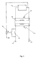
- Figure 1 shows schematically a circuit for an electric appliance according to the invention
- the circuit according to the invention comprises a pair of connectors 1 and 2 powering a primary side 3 of a transformer 4.
- Said transformer 4 provides controlled functional units of an electrical appliance with current.
- One of the connectors 1, 2, is provided with a switch 5 that allows the user to activate and cut off the primary side 3 of the transformer 4 from the connectors 1, 2.
- a secondary side 8 of the transformer 4 is electrically connected to a control device 6 that supervises all the appliance operations including the supply of electrical current.
- a relay 7, arranged in parallel with the switch 5, is connected and activated by the control device 6 in order to by-pass the switch 5.
- the switch 5 is a monostable switch, i.e. a switch having a single stable state and a unstable state that requires constant energy to sustain.
- the stable state is represented by the open position of the switch 5 while the unstable state consists in its closed position.
- the control device 6 can activate again the relay 7 that interrupts the by-pass of the switch 5. Since the latter is in its stable position, i.e. in an open state, the power supply is interrupted.
- the switch 5 can be in the form or a push button or, in case the electrical appliance has a door with a locking mechanism, as in case of a washing machine or an oven, such switch 5 can be integrated in the locking mechanism such that, when the user opens the appliance door acting on the locking means, the control device is activated and the electric appliance is brought in a "ready to be used" state. It is also possible to provide the switch 5 and the relay 7 integrated in a single electrical component that can be activated both manually by a user both mechanically and/or electronically by the feedback of the control device 6.
- circuit according to the invention allows to eliminate any electrical power consumption in an appliance when the latter is switched off.
Landscapes
- Keying Circuit Devices (AREA)
Abstract
The present invention refers to a circuit for an electric appliance.
A circuit according to the invention comprises a control device (6) and a transformer (4) connected with electric current supply connectors (1, 2) for providing controlled functional units of the electric appliance with current, wherein a switch (5) on one of the electric current supply connectors (1, 2) can cut off the transformer (4) from the electric current supply connectors (1, 2). Said circuit being characterised in that said switch (5) is a monostable switch.
A circuit according to the invention comprises a control device (6) and a transformer (4) connected with electric current supply connectors (1, 2) for providing controlled functional units of the electric appliance with current, wherein a switch (5) on one of the electric current supply connectors (1, 2) can cut off the transformer (4) from the electric current supply connectors (1, 2). Said circuit being characterised in that said switch (5) is a monostable switch.
Description
- The present invention refers to a circuit for an electric appliance.
- It is known that many electric appliances, for example household appliances, comprise electronic controls that supervise all the appliance operations. Such electronic controls must be maintained ready for being able to react to inputs. For this reason appliances are constantly powered with a stand-by electric current that is determined by the power use of the implemented electronic circuits and the losses of the power transformer.
- Normally the power consumption due to the stand-by current is relatively low (about 1 Watt) but it can result in a considerable consumption in connection with a large number of electric appliances and with the number of hours each appliance is kept in a stand-by condition during its whole operative life.
- The easiest solution to the problem of avoiding stand-by power consumption in an electric appliance consists in providing the appliance electronic circuit a main switch that allows the appliance to be powered only when the user turns said switch on.
- Such solution is however disadvantageous because such switch not only requires the user to push it for activating the appliance but it also requires a further push to switch the power off. Therefore, for obtaining the minimum stand-by power consumption in an appliance having a main power switch, the user has not only to be able to reach the appliance when it has finished working but he/she has also to remember to turn the main switch off. However it is known that users often forget to switch the appliance off at the end of the machine operations leaving the appliance in a stand-by condition for a relatively long period thereby causing a waste of electrical energy.
- A further solution to the problem of reducing an appliance stand-by power consumption is known from the
American Patent No. US 7,045,917 . Such Patent discloses a circuit arrangement for an electric appliance having a control device and a power supply unit connected to an electric current supply connector for providing controlled functional units of the electrical appliance with current. The electrical power supply connector is provided with a piezo switch that cuts off the power supply unit from the electric current supply connector. The piezo switch, which is open in a non-activated state, is connected with a power semiconductor circuit which, when the piezo switch is operated, connects the control device for activation with the electric power supply connector. - A drawback of the circuit arrangement described in
US 7,045,917 consists in the presence of a semiconductor circuit that does not grant an absolute electrical isolation of the power supply unit from the electric current supply connector when the piezo switch is in an open state. This can cause an electrical current consumption even when the appliance is in a stand-by condition. - The aim of the present invention is therefore to solve the noted problems and thus providing a circuit for an electric appliance that eliminates the current consumption when the appliance is in a stand-by condition.
- Another object of the present invention is to provide a circuit for an electric appliance that allows the latter to be promptly activated without the need of maintaining its electronic circuits constantly powered.
- A further object of the invention is to simplify known circuit arrangement for electric appliances reducing the number of circuit components.
- Advantages, objects, and features of the invention will be set forth in part in the description which follows and in part will become apparent to those having ordinary skill in the art upon examination of the following or may be learned from practice of the invention. The objects and advantages of the invention may be realised and attained as particularly pointed out in the appended claims.
- The accompanying drawing, which is included to provide a further understanding of the invention and is incorporated in and constitute a part of this specification, illustrates a possible embodiment of the invention and together with the description serve to explain the principles of the invention.
- In the drawings:
- Figure 1 shows schematically a circuit for an electric appliance according to the invention;
- With reference to figure 1, the circuit according to the invention comprises a pair of
connectors 1 and 2 powering a primary side 3 of a transformer 4. Said transformer 4 provides controlled functional units of an electrical appliance with current. - One of the
connectors 1, 2, is provided with aswitch 5 that allows the user to activate and cut off the primary side 3 of the transformer 4 from theconnectors 1, 2. - A
secondary side 8 of the transformer 4 is electrically connected to a control device 6 that supervises all the appliance operations including the supply of electrical current. A relay 7, arranged in parallel with theswitch 5, is connected and activated by the control device 6 in order to by-pass theswitch 5. - The
switch 5 is a monostable switch, i.e. a switch having a single stable state and a unstable state that requires constant energy to sustain. The stable state is represented by the open position of theswitch 5 while the unstable state consists in its closed position. - When the electrical appliance is not in use no electrical current passes through the circuit of figure 1. When a user wants to turn the electrical appliance on he/she has only to activate the
switch 5 moving it from its stable position (open position) to its unstable position (closed position). In the short time theswitch 5 is in the closed position the primary side 3 of the transformer 4 is powered and an electrical current flows in thesecondary side 8 powering the control device 6. The control device 6 then, as feedback, activates the relay 7 that short-circuits the terminals of theswitch 5 by-passing it before it moves from the unstable position to the stable position, i.e. before the electrical flow in the primary side 3 is interrupted. - After the intervention of the relay 7 a current supply to the primary side 3 is maintained and therefore the electrical appliance can work regularly. In order to cut off the transformer 4 and the control device 6 from the electric
power supply connectors 1, 2, the control device 6 can activate again the relay 7 that interrupts the by-pass of theswitch 5. Since the latter is in its stable position, i.e. in an open state, the power supply is interrupted. - The
switch 5 can be in the form or a push button or, in case the electrical appliance has a door with a locking mechanism, as in case of a washing machine or an oven,such switch 5 can be integrated in the locking mechanism such that, when the user opens the appliance door acting on the locking means, the control device is activated and the electric appliance is brought in a "ready to be used" state. It is also possible to provide theswitch 5 and the relay 7 integrated in a single electrical component that can be activated both manually by a user both mechanically and/or electronically by the feedback of the control device 6. - Conclusively it can be stated that the circuit according to the invention allows to eliminate any electrical power consumption in an appliance when the latter is switched off.
Claims (6)
- A circuit for an electric appliance having a control device (6) and a transformer (4) connected with electric current supply connectors (1, 2) for providing controlled functional units of the electric appliance with current, wherein a switch (5) on one of the electric current supply connectors (1, 2) can cut off a transformer (4) from the electric current supply connectors (1, 2), characterised in that said switch (5) is a monostable switch.
- A circuit according to claim 1 characterised by comprising a relay (7) arranged in parallel with said switch (5).
- A circuit according to claim 2 wherein said relay (7) is activated by the control device (6).
- A circuit according to claim 2 or 3 wherein the relay (7) and the switch (5) are integrated in a single electrical component.
- An electrical appliance comprising a circuit according to claim 1 to 4.
- An electrical appliance according to claim 5 comprising a door having a locking mechanism associated to said switch (5).
Priority Applications (1)
| Application Number | Priority Date | Filing Date | Title |
|---|---|---|---|
| EP06115482A EP1868276A1 (en) | 2006-06-14 | 2006-06-14 | Circuit for an electric appliance |
Applications Claiming Priority (1)
| Application Number | Priority Date | Filing Date | Title |
|---|---|---|---|
| EP06115482A EP1868276A1 (en) | 2006-06-14 | 2006-06-14 | Circuit for an electric appliance |
Publications (1)
| Publication Number | Publication Date |
|---|---|
| EP1868276A1 true EP1868276A1 (en) | 2007-12-19 |
Family
ID=37387403
Family Applications (1)
| Application Number | Title | Priority Date | Filing Date |
|---|---|---|---|
| EP06115482A Withdrawn EP1868276A1 (en) | 2006-06-14 | 2006-06-14 | Circuit for an electric appliance |
Country Status (1)
| Country | Link |
|---|---|
| EP (1) | EP1868276A1 (en) |
Cited By (3)
| Publication number | Priority date | Publication date | Assignee | Title |
|---|---|---|---|---|
| EP2224595A1 (en) | 2009-02-26 | 2010-09-01 | Diehl AKO Stiftung & Co. KG | Control device |
| DE102010031235A1 (en) | 2010-07-12 | 2012-01-12 | BSH Bosch und Siemens Hausgeräte GmbH | Household appliance i.e. dishwasher, has switching element bringable to open position or closed position by internal control unit, and remaining in open position or closed position during interruption of power supply |
| US8653789B2 (en) | 2009-10-28 | 2014-02-18 | Superior Communications, Inc. | Method and apparatus for recharging batteries in a more efficient manner |
Citations (4)
| Publication number | Priority date | Publication date | Assignee | Title |
|---|---|---|---|---|
| EP0759655A2 (en) * | 1995-08-21 | 1997-02-26 | Dreuth, Hansjürgen | Method and device for reducing power consumption of an electric apparatus fed by a voltage converter |
| DE10037358A1 (en) * | 2000-07-30 | 2002-02-07 | Dewert Antriebs Systemtech | Mains-free switching arrangement for seating and sleeping furniture, avoiding effects of mains electromagnetic fields on user, includes temperature-controlled switches for preventing mains contacts from being switched on |
| JP2002244743A (en) * | 2001-02-19 | 2002-08-30 | Matsushita Electric Ind Co Ltd | Standby power supply circuit |
| US7045917B2 (en) * | 2003-03-15 | 2006-05-16 | Schott Ag | Circuit arrangement for an electric appliance |
-
2006
- 2006-06-14 EP EP06115482A patent/EP1868276A1/en not_active Withdrawn
Patent Citations (4)
| Publication number | Priority date | Publication date | Assignee | Title |
|---|---|---|---|---|
| EP0759655A2 (en) * | 1995-08-21 | 1997-02-26 | Dreuth, Hansjürgen | Method and device for reducing power consumption of an electric apparatus fed by a voltage converter |
| DE10037358A1 (en) * | 2000-07-30 | 2002-02-07 | Dewert Antriebs Systemtech | Mains-free switching arrangement for seating and sleeping furniture, avoiding effects of mains electromagnetic fields on user, includes temperature-controlled switches for preventing mains contacts from being switched on |
| JP2002244743A (en) * | 2001-02-19 | 2002-08-30 | Matsushita Electric Ind Co Ltd | Standby power supply circuit |
| US7045917B2 (en) * | 2003-03-15 | 2006-05-16 | Schott Ag | Circuit arrangement for an electric appliance |
Cited By (5)
| Publication number | Priority date | Publication date | Assignee | Title |
|---|---|---|---|---|
| EP2224595A1 (en) | 2009-02-26 | 2010-09-01 | Diehl AKO Stiftung & Co. KG | Control device |
| US8653789B2 (en) | 2009-10-28 | 2014-02-18 | Superior Communications, Inc. | Method and apparatus for recharging batteries in a more efficient manner |
| US8836282B2 (en) | 2009-10-28 | 2014-09-16 | Superior Communications, Inc. | Method and apparatus for recharging batteries in a more efficient manner |
| DE102010031235A1 (en) | 2010-07-12 | 2012-01-12 | BSH Bosch und Siemens Hausgeräte GmbH | Household appliance i.e. dishwasher, has switching element bringable to open position or closed position by internal control unit, and remaining in open position or closed position during interruption of power supply |
| DE102010031235B4 (en) * | 2010-07-12 | 2016-07-21 | BSH Hausgeräte GmbH | household appliance |
Similar Documents
| Publication | Publication Date | Title |
|---|---|---|
| DK2454746T3 (en) | Electric motor-driven furniture drive system with safety system against initial failure | |
| US20100115317A1 (en) | Generation of an idle mode signal for an electrical control device | |
| WO2012028016A1 (en) | Switch control system with zero power consumption in standby state | |
| CN103250323B (en) | Electronic control device and method for reducing standby power consumption of household appliances | |
| CA2559318A1 (en) | Electrical safety lockout mechanism for power tools and other hazardous machinery | |
| US7045917B2 (en) | Circuit arrangement for an electric appliance | |
| CN101897093B (en) | Circuit configuration for operating a household appliance | |
| EP3042385B1 (en) | Electrical appliance having zero stand-by power consumption | |
| TW200735717A (en) | Load control circuit | |
| EP2056323A1 (en) | Electric device with lower standby power | |
| JP5098620B2 (en) | Power switch circuit | |
| US6417657B2 (en) | Power source connection controller and power source connection controlling method | |
| CN108621095B (en) | Electric tool control device, electric tool system, and electric tool control method | |
| JP2001254950A (en) | Gas cooker control device | |
| CN217469433U (en) | Toaster protection circuit | |
| CN107769384B (en) | Power supply power-on and power-off control device and system | |
| EP2432366B1 (en) | A household appliance with reduced energy consumption | |
| CN221263408U (en) | Hybrid inverter one-key starting circuit and system | |
| US20140084705A1 (en) | Apparatus for saving standby power in a microwave oven | |
| JP5493505B2 (en) | Cooker | |
| EP2659588B1 (en) | A control unit used in household appliances | |
| CN223624851U (en) | Electric operating mechanism in power distribution system | |
| KR100922853B1 (en) | Washing device and its standby power control device | |
| KR100806146B1 (en) | Standby power release device | |
| KR100857784B1 (en) | Internet washing machine and control method in remote control |
Legal Events
| Date | Code | Title | Description |
|---|---|---|---|
| PUAI | Public reference made under article 153(3) epc to a published international application that has entered the european phase |
Free format text: ORIGINAL CODE: 0009012 |
|
| AK | Designated contracting states |
Kind code of ref document: A1 Designated state(s): AT BE BG CH CY CZ DE DK EE ES FI FR GB GR HU IE IS IT LI LT LU LV MC NL PL PT RO SE SI SK TR |
|
| AX | Request for extension of the european patent |
Extension state: AL BA HR MK YU |
|
| AKX | Designation fees paid | ||
| REG | Reference to a national code |
Ref country code: DE Ref legal event code: 8566 |
|
| STAA | Information on the status of an ep patent application or granted ep patent |
Free format text: STATUS: THE APPLICATION IS DEEMED TO BE WITHDRAWN |
|
| 18D | Application deemed to be withdrawn |
Effective date: 20080620 |