EP1868109A1 - Event signalling between peripheral modules and a processing unit - Google Patents
Event signalling between peripheral modules and a processing unit Download PDFInfo
- Publication number
- EP1868109A1 EP1868109A1 EP06012059A EP06012059A EP1868109A1 EP 1868109 A1 EP1868109 A1 EP 1868109A1 EP 06012059 A EP06012059 A EP 06012059A EP 06012059 A EP06012059 A EP 06012059A EP 1868109 A1 EP1868109 A1 EP 1868109A1
- Authority
- EP
- European Patent Office
- Prior art keywords
- processing unit
- peripheral
- event
- module
- telegram
- Prior art date
- Legal status (The legal status is an assumption and is not a legal conclusion. Google has not performed a legal analysis and makes no representation as to the accuracy of the status listed.)
- Ceased
Links
- 238000012545 processing Methods 0.000 title claims abstract description 107
- 230000011664 signaling Effects 0.000 title claims abstract description 91
- 230000002093 peripheral effect Effects 0.000 title claims description 122
- 238000000034 method Methods 0.000 claims abstract description 36
- 230000005540 biological transmission Effects 0.000 claims description 24
- 230000004044 response Effects 0.000 claims description 17
- 238000005516 engineering process Methods 0.000 claims description 6
- 230000008878 coupling Effects 0.000 claims description 3
- 238000010168 coupling process Methods 0.000 claims description 3
- 238000005859 coupling reaction Methods 0.000 claims description 3
- 238000002372 labelling Methods 0.000 claims 1
- 238000004891 communication Methods 0.000 abstract description 13
- 238000010276 construction Methods 0.000 description 3
- 238000013461 design Methods 0.000 description 3
- 230000001360 synchronised effect Effects 0.000 description 3
- 238000012546 transfer Methods 0.000 description 2
- 238000006243 chemical reaction Methods 0.000 description 1
- 238000011161 development Methods 0.000 description 1
- 238000010586 diagram Methods 0.000 description 1
- 238000011156 evaluation Methods 0.000 description 1
- 238000013439 planning Methods 0.000 description 1
- 238000012913 prioritisation Methods 0.000 description 1
- 230000035484 reaction time Effects 0.000 description 1
- 230000002269 spontaneous effect Effects 0.000 description 1
Images


Classifications
-
- G—PHYSICS
- G06—COMPUTING; CALCULATING OR COUNTING
- G06F—ELECTRIC DIGITAL DATA PROCESSING
- G06F13/00—Interconnection of, or transfer of information or other signals between, memories, input/output devices or central processing units
- G06F13/38—Information transfer, e.g. on bus
- G06F13/42—Bus transfer protocol, e.g. handshake; Synchronisation
- G06F13/4247—Bus transfer protocol, e.g. handshake; Synchronisation on a daisy chain bus
- G06F13/426—Bus transfer protocol, e.g. handshake; Synchronisation on a daisy chain bus using an embedded synchronisation, e.g. Firewire bus, Fibre Channel bus, SSA bus
Definitions
- the invention relates to a method for event signaling between at least one peripheral module and a processing unit by means of a system bus, wherein the system bus is operated by a system bus master which can read or send data from the peripheral modules, the data being composed of individual characters, which are transcribed for transmission in a physical layer at a transmitter by a coder in a larger character space and converted back at a receiver by a decoder, wherein for the data transmission, a telegram method according to the request / response paradigm is used in which certain characters from the larger character space for characterizing the start and end of a telegram and a standard idle character in telegram pauses used to synchronize a connection between the sender and the receiver.
- the invention further relates to a bus protocol based on said method and to a peripheral module, a processing unit and an event signaling hub according to said method. Finally, the invention relates to a system of said components in which said method finds application using said bus protocol.
- Such a method and / or a system with the named components using said bus protocol is used in all areas in which peripheral modules communicate with a processing unit via a system bus, as is the case in particular in automation technology.
- the main requirements are as follows:
- the system module master must access the I / O modules as quickly as possible and with less speed via direct access Latency can be accessed, the peripheral modules should be able to report as soon as possible pending alarms or pending communication requirements to the system bus master and the communication connection of the peripheral modules must be cost-effectively feasible.
- the system bus master is either the (central) processing unit (CPU), which processes the data of the peripheral modules, or an interface module, which decentrally establishes the coupling between the peripheral modules and the central processing unit via a fieldbus.
- the peripheral modules are the input and output modules that receive the data from the system bus master or from which the system bus master can read data.
- the I / O modules connect to the automation process. Furthermore, for example, when connecting the components to a backplane structure, it is possible to use a hub which behaves like an I / O module with regard to event signaling.
- the pending jobs are prioritized by a scheduler in the system bus interface of the system bus master and sent to the I / O modules via the system bus.
- the I / O modules may only send data to the bus if they have received a request from the CPU, ie the system bus master responds to a peripheral module by means of a request and expects a corresponding response. Due to process or diagnostic events, the I / O modules must also be able to send a message to the CPU which must be transported to the CPU as quickly as possible and processed there.
- peripheral modules typically up to 64
- the transport of the messages to the CPU must be controlled by a special mechanism since, in the worst case, all peripheral modules want to send a message to the CPU at the same time.
- Profibus also supports a polling procedure in which the master polls all slaves, ie the mentioned peripheral modules, and reads the data from the I / O modules or writes them to the I / O modules. Also in this case, the response or reporting time depends on the polling cycle of the CPU until a module can signal to the CPU that an alarm or communication request is present.
- the switched networks have prevailed at 100 Mbps.
- the throughput and the response time depend to a great extent on the available message memory in the individual switches and the arrangement (topology) of the switches and the nodes.
- Each participant may send at any time.
- the CPU in case of event signaling. This depends on the remaining telegram volume. If there is a collision because two parties are transmitting at the same time, this collision is resolved by the memory in the switch. The message that arrives later will be cached in the switch and sent after the first message has been completed.
- Ethernet offers baud rates of 10, 100, and 1000 Mbps and above.
- an additional hardware line is provided for the message path from the peripheral modules to the CPU.
- the system bus master had to read out the status from the I / O modules and determine which module would like to send a message to the CPU, whereupon the CPU could then actively read the message from the I / O module. This resulted in a high latency because the CPU did not immediately know which I / O module had which message.
- the CPU can not know which module would like to send a message to the CPU at what point in time, a solution is required in which a message can be transmitted from the peripheral modules to the processing unit independently of the message processing by the CPU. Furthermore, the system bus should be able to work with baud rates of several hundred Mbps.
- a telegram method according to the request / response paradigm is suitable in which the data, which are composed of individual characters, for transmission in a physical layer at a transmitter by a coder into a larger character space be recoded at a receiver by a decoder and certain characters from the larger character space to mark the start and end of a telegram and a standard idle character in telegram pauses used to synchronize a connection between the sender and the receiver.
- an 8B / 10B encoding is known, which is also used in Gigabit Ethernet.
- the 10-bit characters are converted back to 8-bit characters by a decoder.
- the 10-bit characters have at least four level changes, whereby DC-freedom is ensured and clock information for synchronization of the transmission stations can be obtained from the data stream.
- a maximum of 256 characters are possible, which can be distributed by the conversion to the 10 bits to 1024 characters.
- the encoding rules used state that the 256 characters are split into two disjoint character spaces in 10-bit character space, occupying 512 10-bit characters. This leaves 512 characters that are not used as data characters. From this additional set of characters, certain characters stand out due to their "safety margin" to other characters. These characters are used to mark the start and end of a telegram and to keep the connection between the send port and the receive port synchronized in the telegram pauses.
- This 8B / 10B encoding is actually a combined 5B / 6B and 3B / 4B encoding.
- the DC-free and integrated synchronization however, you buy with a 25% higher demand for bandwidth.
- With the 64B / 66B encoding exists a further development of this method, in which only about 3% bandwidth is needed more.
- the invention has for its object to provide a method by which the peripheral modules, regardless of the telegram traffic, which is initiated by the processing unit, can signal a present message to the processing unit.
- Another object of the present invention is to provide a bus protocol which enables such communication between the peripheral modules and the processing unit on the system bus.
- the invention is further based on the object of specifying a peripheral module, a processing unit and a hub and an existing system consisting of these components, wherein the components means for signaling a present at the peripheral modules message to the processing unit regardless of the telegram traffic, initiated by the processing unit is, have.
- This object is achieved in a method of the type mentioned in that an I / O module that wants to signal the processing unit an event sends to the processing unit in a telegram pause instead of the standard idle character a signaling sequence consisting of an alarm-idle character and an alarm identifier containing information about the event in question as well as the module address of the peripheral module on which the event is present, the information about the Event also be recoded into the larger drawing space.
- the object is further achieved by a bus protocol, a peripheral module, a processing unit, a hub and a system of the type mentioned above with the features mentioned in claims 9, 12, 18, 23 and 26, respectively.
- the processing unit receives the information via the signaling sequence that there is a message from a specific peripheral module which is to be fetched by the processing unit.
- the relevant peripheral module in the telegram pauses instead of the standard idle character sends an alarm-idle character, followed by further information in the alarm identifier
- the telegram traffic (request / response telegrams) becomes functional and time-delayed by the signaling sequence practically unaffected. This relieves the system bus master of coordination tasks.
- the processing unit can determine the most varied information based on the signaling sequences. For example, the processing unit immediately recognizes from which peripheral module which message is present. Furthermore, this mechanism eliminates one or more additional hardware lines for signaling messages from the peripheral modules to the processing unit.
- the signaling sequence is interrupted at any point in the character string when a request or a response message is sent. This ensures that the normal data transfer is not affected.
- this mechanism for the first signaling sequence indicates a process alarm, a calculable, deterministic response time can be specified. This consists of the pure transit time of the signaling sequence and a possible latency, if a maximum long telegram before the signaling sequence must be transmitted together.
- the processing unit is used as a system bus master, which eliminates the need for an additional interface module.
- an interface module is alternatively used as a system bus master, which establishes a coupling between the peripheral modules and the processing unit via a field bus, whereby a discharge of the processing unit is achieved.
- the signaling sequence is sent by the peripheral module until the processing unit signals to the peripheral module through appropriate telegrams that the signaling sequence has arrived at the processing unit, whereby a maximum of security is achieved.
- the processing unit and the peripheral modules are interconnected in a daisy-chain or backplane configuration.
- daisy-chain or backplane configuration are the usual basic designs of a system bus, which can be easily realized with the invention.
- the method is provided for event signaling in the field of automation technology, wherein the processing unit is designed as a programmable logic controller.
- the processing unit is designed as a programmable logic controller.
- the peripheral module has a sample stage for storing a message to be sent Signaling sequence on. Since only one signaling sequence can be sent simultaneously, it may be necessary to determine the first event to be reported from possibly several present events in accordance with rules to be defined, with the resulting signaling sequence being recorded in the sample stage.
- the peripheral module has at least one further transmitter and at least one further receiver for connecting further peripheral modules.
- This allows a daisy-chain connection in which the processing unit and the peripheral modules are connected in series.
- the processing unit does not necessarily have to be at one end of the row, but it can also be present in the middle of the row.
- the peripheral module has a hold stage for storing signaling sequences of further peripheral modules.
- the signaling sequence is then fed to the sample stage.
- the peripheral module has a priority level for evaluating both its own signaling sequences and those of other peripheral modules and forwarding the signaling sequence with the highest priority.
- the thus prioritized signaling sequences have in their alarm identifier a field for the assigned priority, so that the importance of the corresponding event can be read directly from the signaling sequence.
- the processing unit has at least one further transmitter and at least one further receiver for connecting further peripheral modules.
- the processing unit can be interconnected in a daisy-chain design between two peripheral modules or in a backplane structure without additional hub.
- the processing unit has a hold stage for each receiver to store signaling sequences of the peripheral modules. If signaling sequences are present at the same time, then the event to be processed first can be determined according to rules to be defined.
- the processing unit has a priority level for evaluating the signaling sequences from the peripheral modules and processing the highest priority signaling sequence.
- the hub also has a sample and / or hold stage for storing the signaling sequences to be transmitted and / or received.
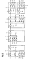
- FIG. 1 shows a flow diagram of a communication between a processing unit 1 and a peripheral module 2.
- the transmission between these two modules 1, 2 takes place via point-to-point connections between the communication ports 3, 4.
- the transmission between a transmitter 3 and a receiver 4 may be e.g. based on LVDS (Low Voltage Differential Signaling). This is a differential interface standard for high-speed data transmission (ANSI / TIA / EIA-644-1995, IEEE 1596.3-1996).
- LVDS Low Voltage Differential Signaling
- the individual characters which make up the data to be transmitted, are recoded into a larger character space.
- This can for example be done with an 8B / 10B coding, ie an 8-bit character is converted at the transmitter 3 by a coder into a 10-bit character and at the receiver 4 by a decoder back into an 8-bit character.
- an unused character stock remains, from which certain characters protrude due to their "safety margin".
- comma characters which, even with any combination of these characters and all other characters, do not create commas across character boundaries. These characters are therefore ideal for finding the character boundaries within the data stream.
- the standard idle character 5 is transmitted in the telegram pauses between ports 3, 4 of two modules. In order to the transmission link is also synchronized in the telegram pauses.
- the processing unit 1 sends a request telegram 6 to the peripheral module 2 (upper image in the figure) and receives a response telegram 7 from the peripheral module 2 (second image from above). If there is an event present in the peripheral module 2 that wishes to report this to the processing unit 1, it sends instead of the standard idle character 5 a signaling sequence 8 which is repeated until the processing unit 1 signals the peripheral module 2 by corresponding telegrams in that the message has arrived at the processing unit 1. Meanwhile, the processing unit 1 can also send another request 6 to the peripheral module 2 (second image from below). In this case, the peripheral module 2 can immediately return the response 7 to the request 6 of the processing unit 1, since the signaling sequence 8 can be interrupted at each character boundary.
- This consists of an alarm-idle character 9 and an alarm identifier 10.
- the alarm-idle character 9 is another character from the group of comma characters
- the alarm identifier 10 further information about the message in question such as the module address of the relevant peripheral module 2, a priority of the event message 8 and which message / information is present on the peripheral module 2 supplies.
- FIG. 3 shows an embodiment of the system according to the invention in a daisy-chain design.
- the system has a peripheral module 2 to the left of the processing unit 1 and further peripheral modules 2 to the right of the processing unit 1.
- each peripheral module 2 in this example, three different alarm messages 14-16 may be present. These are fed to a priority stage 13, which evaluates the signaling sequences 8 and forwards the signaling sequence 8 with the highest priority. If two signaling sequences 8 with the same priority exist, then a priority scheme defined on the system bus applies, which determines in this case which signaling sequence 8 is forwarded.
- the neighboring modules 2 and the processing unit 1 have a hold stage 12, which receives the incoming signaling sequences 8.
- the processing unit 1 has two hold stages 12, in which the incoming signaling sequences 8 are stored and supplied from here to the priority stage 13, which decides which of the possible alarm messages 14-16 is processed first.
- the system in addition to the processing unit 1 on the left in the image and the peripheral modules 2 on the right, the system also has a hub 17, by means of which the connection between the peripheral modules 2 and the processing unit 1 is established. Structure and operation of the peripheral modules 2 is described as in the outer peripheral modules 2 in the daisy-chain structure in Figure 3.
- the signaling sequences 8 sent by the peripheral modules 2 become stored in the hub 17 in each case a hold stage 12, ie, the hub 17 has a hold stage 12 for each peripheral module 2 and for each module slot on the backplane.
- These signaling sequences 8 are now forwarded with possible own alarm messages 14-16 of the hub 17 to the priority level 13 of the hub 17 for prioritization.
- the resulting signaling sequence 8, which is sent to the processing unit 1, is stored again in a sample stage 11 of the hub.
- only one signaling sequence 8 arrives in the processing unit 1, so that the processing unit 1, unlike the one described in the daisy-chain structure, has only one hold stage 12 and thus also does not require a priority stage 13.
- FIG. 5 shows an embodiment of the system according to the invention in a construction with two hubs 17.
- the structure essentially corresponds to that of FIG. 4, with an additional hub 17 being located to the left of the processing unit 1.
- the other peripheral modules 2 which can be connected to this additional hub 17.
- the processing unit 1 in the structure in this FIG. 5 requires two hold stages 12, in which the signaling sequences 8 sent by the two hubs 17 are stored. It follows that the processing unit 1 in the structure with two hubs 17 also requires a priority stage 13 for prioritizing the incoming signaling sequences 8.
- the processing unit 1 in the structure with two hubs 17 also requires a priority stage 13 for prioritizing the incoming signaling sequences 8.
- the invention relates to a method, a bus protocol, an I / O module, a processing unit, a hub and a system of said components for event signaling between at least one peripheral module and a processing unit by means of a system bus.
- the data to be transmitted is encoded into a larger character space, from which a standard idle character in Telegram pauses are used to synchronize a connection between transmitter and receiver.
- the invention has for its object to be able to signal a present at the peripheral modules message regardless of telegram traffic, which is initiated by the processing unit to the processing unit.
- an I / O module which wishes to signal an event to the processing unit sends to the processing unit, in a message pause, instead of the standard idle character, a signaling sequence consisting of an alarm-idle character and an alarm identifier. contains the information about the event in question as well as the module address of the peripheral module on which the event is present, the information about the event also being recoded into the larger character space.
Landscapes
- Engineering & Computer Science (AREA)
- Theoretical Computer Science (AREA)
- Physics & Mathematics (AREA)
- General Engineering & Computer Science (AREA)
- General Physics & Mathematics (AREA)
- Bus Control (AREA)
Abstract
Description
Die Erfindung betrifft ein Verfahren zur Ereignissignalisierung zwischen zumindest einem Peripheriemodul und einer Verarbeitungseinheit mittels eines Systembusses, wobei der Systembus von einem Systembus-Master betrieben wird, der von den Peripheriemodulen Daten lesen oder an diese senden kann, wobei sich die Daten aus einzelnen Zeichen zusammensetzen, die zur Übertragung in einer Bitübertragungsschicht bei einem Sender durch einen Kodierer in einen größeren Zeichenraum umkodiert und bei einem Empfänger durch einen Dekodierer wieder zurückgewandelt werden, wobei für die Datenübertragung ein Telegrammverfahren nach dem Request/Response-Paradigma verwendet wird, bei dem bestimmte Zeichen aus dem größeren Zeichenraum zur Kennzeichnung von Start und Ende eines Telegramms und ein Standard-Idle-Zeichen in Telegrammpausen zur Synchronisierung einer Verbindung zwischen dem Sender und dem Empfänger verwendet werden.The invention relates to a method for event signaling between at least one peripheral module and a processing unit by means of a system bus, wherein the system bus is operated by a system bus master which can read or send data from the peripheral modules, the data being composed of individual characters, which are transcribed for transmission in a physical layer at a transmitter by a coder in a larger character space and converted back at a receiver by a decoder, wherein for the data transmission, a telegram method according to the request / response paradigm is used in which certain characters from the larger character space for characterizing the start and end of a telegram and a standard idle character in telegram pauses used to synchronize a connection between the sender and the receiver.
Die Erfindung betrifft ferner ein Busprotokoll, das auf dem genannten Verfahren basiert, sowie ein Peripheriemodul, eine Verarbeitungseinheit und einen Hub zur Ereignissignalisierung nach dem genannten Verfahren. Schließlich betrifft die Erfindung ein System aus den genannten Komponenten, in dem das genannte Verfahren unter Verwendung des genannten Busprotokolls Anwendung findet.The invention further relates to a bus protocol based on said method and to a peripheral module, a processing unit and an event signaling hub according to said method. Finally, the invention relates to a system of said components in which said method finds application using said bus protocol.
Ein derartiges Verfahren bzw. ein derartiges System mit den genannten Komponenten unter Verwendung des genannten Busprotokolls kommt in allen Bereichen zum Einsatz, in denen Peripheriemodule mit einer Verarbeitungseinheit über einen Systembus kommunizieren, wie dies insbesondere in der Automatisierungstechnik der Fall ist. Dabei bestehen folgende Hauptanforderungen: Auf die Peripheriemodule muss vom Systembus-Master per Direktzugriff möglichst schnell und mit geringer Latenzzeit zugegriffen werden können, die Peripheriemodule sollen möglichst schnell anstehende Alarme bzw. anstehende Kommunikationsanforderungen an den Systembus-Master melden können und die Kommunikationsanbindung der Peripheriemodule muss kostengünstig realisierbar sein. Als Systembus-Master fungiert dabei entweder die (zentrale) Verarbeitungseinheit (CPU), die die Daten der Peripheriemodule bearbeitet, oder ein Interface-Modul, welches über einen Feldbus dezentral die Kopplung zwischen den Peripheriemodulen und der zentralen Verarbeitungseinheit herstellt. Die Peripheriemodule sind die Ein- und Ausgabemodule, die von dem Systembus-Master die Daten erhalten oder von denen der Systembus-Master Daten lesen kann. In der Automatisierungstechnik stellen die Peripheriemodule die Verbindung zum Automatisierungsprozess her. Weiterhin ist beispielsweise bei einer Verschaltung der Komponenten nach einem Backplane-Aufbau der Einsatz eines Hubs möglich, der sich bezüglich der Ereignissignalisierung wie ein Peripheriemodul verhält.Such a method and / or a system with the named components using said bus protocol is used in all areas in which peripheral modules communicate with a processing unit via a system bus, as is the case in particular in automation technology. The main requirements are as follows: The system module master must access the I / O modules as quickly as possible and with less speed via direct access Latency can be accessed, the peripheral modules should be able to report as soon as possible pending alarms or pending communication requirements to the system bus master and the communication connection of the peripheral modules must be cost-effectively feasible. In this case, the system bus master is either the (central) processing unit (CPU), which processes the data of the peripheral modules, or an interface module, which decentrally establishes the coupling between the peripheral modules and the central processing unit via a fieldbus. The peripheral modules are the input and output modules that receive the data from the system bus master or from which the system bus master can read data. In automation technology, the I / O modules connect to the automation process. Furthermore, for example, when connecting the components to a backplane structure, it is possible to use a hub which behaves like an I / O module with regard to event signaling.
Unabhängig von der Verschaltung folgt der Kommunikationsablauf auf dem Systembus der bekannten Vorgehensweise: Durch einen Scheduler im Systembus-Interface des Systembus-Masters werden die anstehenden Aufträge priorisiert und über den Systembus an die Peripheriemodule versendet. Die Peripheriemodule dürfen nur dann Daten auf den Bus senden, wenn sie eine Aufforderung von der CPU erhalten haben, d.h. der Systembus-Master spricht ein Peripheriemodul durch einen Request an und erwartet eine entsprechende Response. Aufgrund von Prozessoder Diagnoseereignissen müssen die Peripheriemodule aber auch von sich aus eine Meldung an die CPU absetzen können, die möglichst schnell zur CPU transportiert und dort verarbeitet werden muss. Da auf einem Systembus eine große Anzahl von Peripheriemodulen (typischerweise bis zu 64) gesteckt sein können, muss durch einen speziellen Mechanismus der Transport der Meldungen zur CPU geregelt werden, da im schlimmsten Fall alle Peripheriemodule gleichzeitig eine Meldung an die CPU absetzen wollen. Prinzipiell kann der Buszugriff der einzelnen Busteilnehmer/Stationen, falls sie eine Nachricht versenden wollen, auf unterschiedliche Art und Weise festgelegt werden.Regardless of the interconnection, the communication sequence on the system bus follows the familiar procedure: The pending jobs are prioritized by a scheduler in the system bus interface of the system bus master and sent to the I / O modules via the system bus. The I / O modules may only send data to the bus if they have received a request from the CPU, ie the system bus master responds to a peripheral module by means of a request and expects a corresponding response. Due to process or diagnostic events, the I / O modules must also be able to send a message to the CPU which must be transported to the CPU as quickly as possible and processed there. Since a large number of peripheral modules (typically up to 64) can be plugged into a system bus, the transport of the messages to the CPU must be controlled by a special mechanism since, in the worst case, all peripheral modules want to send a message to the CPU at the same time. In principle, the bus access of the individual bus stations / stations, if they have a Want to send a message in different ways.
Bei Profibus z.B. gibt es einen Token, der zwischen den Master-Stationen ausgetauscht wird. Nur die Station, die den Token hat, darf auf den Bus eine Nachricht senden. Alle anderen Stationen sind passiv. Dies bedeutet, dass Stationen, also die genannten Peripheriemodule, nur dann eine Nachricht an die CPU senden dürfen, falls sie den Token haben. Dies führt dazu, dass die Reaktionszeit durch den Umlauf des Tokens bestimmt wird. Das Tokenverfahren (Tokenring, -bus) arbeitet aktuell bis zu Baudraten von 100 MBit/s. Es ist kein System bekannt, das mit höheren Baudraten arbeitet.For Profibus e.g. There is a token exchanged between the master stations. Only the station that has the token is allowed to send a message to the bus. All other stations are passive. This means that stations, that is the mentioned peripheral modules, are only allowed to send a message to the CPU if they have the token. This results in that the reaction time is determined by the circulation of the token. The token method (token ring, -bus) currently works up to baud rates of 100 Mbit / s. There is no known system that operates at higher baud rates.
Profibus unterstützt auch ein Polling-Verfahren, bei dem der Master alle Slaves, also die genannten Peripheriemodule, abpollt und die Daten aus den Peripheriemodulen liest oder in die Peripheriemodule schreibt. Auch in diesem Fall hängt die Reaktions- bzw. Meldezeit vom Poll-Zyklus der CPU ab, bis ein Modul der CPU signalisieren kann, dass eine Alarm- oder eine Kommunikationsanforderung vorliegt.Profibus also supports a polling procedure in which the master polls all slaves, ie the mentioned peripheral modules, and reads the data from the I / O modules or writes them to the I / O modules. Also in this case, the response or reporting time depends on the polling cycle of the CPU until a module can signal to the CPU that an alarm or communication request is present.
Bei Ethernet haben sich bei 100 MBit/s die geswitchten Netze durchgesetzt. Der Durchsatz und die Reaktionszeit hängt dabei in starkem Maße von dem verfügbaren Telegrammspeicher in den einzelnen Switches und der Anordnung (Topologie) der Switches und der Teilnehmer ab. Jeder Teilnehmer darf zu jedem Zeitpunkt senden. Es gibt allerdings keine Garantie, wann die Nachricht beim Empfänger, der CPU im Falle einer Ereignissignalisierung, ankommt. Dies hängt von dem restlichen Telegrammaufkommen ab. Kommt es zu einer Kollision, da zwei Teilnehmer gleichzeitig senden, wird diese Kollision durch den Speicher im Switch aufgelöst. Die etwas später eintreffende Nachricht wird im Switch zwischengespeichert und nach dem Abschluss der ersten Nachricht versendet. Mittlerweile gibt es auch Systeme (z.B. PROFINET), die durch eine Planung die Kollision bei Ethernet verhindern, dies führt aber wieder dazu, dass die Teilnehmer ihre spontanen Kommunikationsanforderungen, wie z.B. Alarme, nur zu bestimmten Zeiten versenden dürfen. Ethernet bietet Baudraten von 10, 100 und 1000 MBit/s und darüber an.With Ethernet, the switched networks have prevailed at 100 Mbps. The throughput and the response time depend to a great extent on the available message memory in the individual switches and the arrangement (topology) of the switches and the nodes. Each participant may send at any time. However, there is no guarantee when the message arrives at the receiver, the CPU in case of event signaling. This depends on the remaining telegram volume. If there is a collision because two parties are transmitting at the same time, this collision is resolved by the memory in the switch. The message that arrives later will be cached in the switch and sent after the first message has been completed. Meanwhile there are also systems (eg PROFINET), which prevent the collision with Ethernet by a planning, but this leads again to the fact that the participants their spontaneous communication requirements, such as alarms, only allowed to ship at certain times. Ethernet offers baud rates of 10, 100, and 1000 Mbps and above.
Es gibt auch noch Systeme (CAN-basierte Lösungen), bei denen der Buszugriff und die Telegrammübertragung durch eine reine Prioritätssteuerung geregelt werden. Jedes Telegramm enthält ein Prio-Feld, das die Nachrichten eindeutig priorisiert. Die Buszugriffslogik wertet dieses Feld aus und lässt die Nachricht mit der höchsten Priorität passieren. Diese Art der Nachrichtenübermittlung ist bei Baudraten bis etwa 10 MBit/s machbar, darüber ist kein System bekannt, das mit einer derartigen Lösung arbeitet.There are also systems (CAN-based solutions) in which the bus access and the telegram transmission are controlled by a pure priority control. Each telegram contains a priority field, which clearly prioritizes the messages. The bus access logic evaluates this field and passes the message with the highest priority. This type of messaging is feasible at baud rates up to about 10 Mbps, no system is known about it, which works with such a solution.
Bei vielen Automatisierungssystemen wird für den Meldeweg von den Peripheriemodulen zur CPU eine zusätzliche Hardware-Leitung vorgesehen. Hier musste der Systembus-Master bei aktiver Leitung den Status aus den Peripheriemodulen auslesen und ermitteln, welche Baugruppe eine Meldung an die CPU absetzen möchte, worauf die CPU dann die Meldung aktiv aus dem Peripheriemodul auslesen konnte. Dies hatte eine hohe Latenzzeit zur Folge, da die CPU nicht sofort wusste, auf welchem Peripheriemodul welche Meldung vorliegt.In many automation systems, an additional hardware line is provided for the message path from the peripheral modules to the CPU. When the line was active, the system bus master had to read out the status from the I / O modules and determine which module would like to send a message to the CPU, whereupon the CPU could then actively read the message from the I / O module. This resulted in a high latency because the CPU did not immediately know which I / O module had which message.
Da die CPU nicht wissen kann, welche Baugruppe zu welchem Zeitpunkt eine Meldung an die CPU senden möchte, ist eine Lösung erforderlich, bei der unabhängig von der Telegrammbearbeitung durch die CPU eine Meldung von den Peripheriemodulen an die Verarbeitungseinheit übermittelt werden kann. Des Weiteren sollte der Systembus mit Baudraten von mehreren hundert MBit/s arbeiten können. Als ein der Erfindung zugrunde liegendes Verfahren bzw. System ist daher ein Telegrammverfahren nach dem Request/Response-Paradigma geeignet, bei dem die Daten, die sich aus einzelnen Zeichen zusammensetzen, zur Übertragung in einer Bitübertragungsschicht bei einem Sender durch einen Kodierer in einen größeren Zeichenraum umkodiert und bei einem Empfänger durch einen Dekodierer wieder zurückgewandelt werden und bestimmte Zeichen aus dem größeren Zeichenraum zur Kennzeichnung von Start und Ende eines Telegramms und ein Standard-Idle-Zeichen in Telegrammpausen zur Synchronisierung einer Verbindung zwischen dem Sender und dem Empfänger verwendet werden.Since the CPU can not know which module would like to send a message to the CPU at what point in time, a solution is required in which a message can be transmitted from the peripheral modules to the processing unit independently of the message processing by the CPU. Furthermore, the system bus should be able to work with baud rates of several hundred Mbps. As a method or system on which the invention is based, therefore, a telegram method according to the request / response paradigm is suitable in which the data, which are composed of individual characters, for transmission in a physical layer at a transmitter by a coder into a larger character space be recoded at a receiver by a decoder and certain characters from the larger character space to mark the start and end of a telegram and a standard idle character in telegram pauses used to synchronize a connection between the sender and the receiver.
Aus der
Auf der 8-Bit-Ebene sind maximal 256 Zeichen möglich, die durch die Umsetzung auf die 10 Bit auf 1024 Zeichen verteilt werden können. Die verwendeten Kodierungsregeln legen fest, dass die 256 Zeichen auf zwei disjunkte Zeichenräume im 10-Bit-Zeichenraum aufgeteilt werden, was 512 10-Bit-Zeichen belegt. Somit bleiben 512 Zeichen übrig, die nicht als Datenzeichen genutzt werden. Aus diesem zusätzlichen Zeichenvorrat ragen bestimmte Zeichen aufgrund ihres "Sicherheitsabstandes" zu anderen Zeichen heraus. Diese Zeichen werden dazu verwendet, um den Start und das Ende eines Telegramms zu kennzeichnen und in den Telegrammpausen die Verbindung zwischen dem Sendeport und dem Empfangsport synchronisiert zu halten. Unter diesen speziellen Zeichen gibt es eine weitere Klasse von Zeichen - auch Komma-Zeichen genannt -, die selbst bei jeder beliebigen Kombination aus diesen Zeichen und allen anderen Zeichen keine Kommas über Zeichengrenzen hinweg erzeugen. Diese Zeichen eignen sich deshalb hervorragend, um die Zeichengrenzen innerhalb des Datenstroms zu ermitteln. In dieser 8B/10B-Kodierung gibt es drei solcher Komma-Zeichen. Eines davon, das Standard-Idle-Zeichen, wird in den Telegrammpausen zwischen den Ports zweier Baugruppen übertragen. Damit ist die Übertragungsstrecke auch in den Telegrammpausen synchronisiert. Dies gilt für die Richtung von der CPU zu den Peripheriemodulen als auch für die Richtung von den Peripheriemodulen zur CPU.On the 8-bit level, a maximum of 256 characters are possible, which can be distributed by the conversion to the 10 bits to 1024 characters. The encoding rules used state that the 256 characters are split into two disjoint character spaces in 10-bit character space, occupying 512 10-bit characters. This leaves 512 characters that are not used as data characters. From this additional set of characters, certain characters stand out due to their "safety margin" to other characters. These characters are used to mark the start and end of a telegram and to keep the connection between the send port and the receive port synchronized in the telegram pauses. Among these special characters, there is another class of characters - also called comma characters - that will not produce commas across character boundaries, even with any combination of these characters and all other characters. These characters are therefore ideal for finding the character boundaries within the data stream. There are three such comma characters in this 8B / 10B encoding. One of these, the standard idle character, is transmitted in the telegram pauses between the ports of two modules. This is the transmission path also synchronized in the telegram pauses. This applies to the direction from the CPU to the peripheral modules as well as the direction from the peripheral modules to the CPU.
Diese 8B/10B-Kodierung ist eigentlich eine kombinierte 5B/6Bund 3B/4B-Kodierung. Die Gleichstromfreiheit und integrierte Synchronisation erkauft man sich jedoch mit einem 25% höheren Bedarf an Bandbreite. Mit der 64B/66B-Kodierung existiert eine Weiterentwicklung dieses Verfahrens, bei dem nur noch ca. 3% Bandbreite mehr benötigt wird.This 8B / 10B encoding is actually a combined 5B / 6B and 3B / 4B encoding. The DC-free and integrated synchronization, however, you buy with a 25% higher demand for bandwidth. With the 64B / 66B encoding exists a further development of this method, in which only about 3% bandwidth is needed more.
Der Erfindung liegt die Aufgabe zugrunde, ein Verfahren anzugeben, mit dem die Peripheriemodule unabhängig von dem Telegrammverkehr, der durch die Verarbeitungseinheit initiiert wird, eine vorliegende Meldung an die Verarbeitungseinheit signalisieren können. Der Erfindung liegt weiter die Aufgabe zugrunde, ein Busprotokoll anzugeben, das eine derartige Kommunikation zwischen den Peripheriemodulen und der Verarbeitungseinheit auf dem Systembus ermöglicht. Der Erfindung liegt ferner die Aufgabe zugrunde, ein Peripheriemodul, eine Verarbeitungseinheit und einen Hub sowie ein aus diesen Komponenten bestehendes System anzugeben, wobei die Komponenten Mittel zur Signalisierung einer bei den Peripheriemodulen vorliegenden Meldung an die Verarbeitungseinheit unabhängig von dem Telegrammverkehr, der durch die Verarbeitungseinheit initiiert wird, aufweisen.The invention has for its object to provide a method by which the peripheral modules, regardless of the telegram traffic, which is initiated by the processing unit, can signal a present message to the processing unit. Another object of the present invention is to provide a bus protocol which enables such communication between the peripheral modules and the processing unit on the system bus. The invention is further based on the object of specifying a peripheral module, a processing unit and a hub and an existing system consisting of these components, wherein the components means for signaling a present at the peripheral modules message to the processing unit regardless of the telegram traffic, initiated by the processing unit is, have.
Diese Aufgabe wird bei einem Verfahren der eingangs genannten Art dadurch gelöst, dass ein Peripheriemodul, das der Verarbeitungseinheit ein Ereignis signalisieren möchte, an die Verarbeitungseinheit in einer Telegrammpause anstelle des Standard-Idle-Zeichens eine Signalisierungssequenz sendet, die aus einem Alarm-Idle-Zeichen und einem Alarm-Identifier besteht, der Informationen über das betreffende Ereignis sowie die Modul-Adresse des Peripheriemoduls, auf dem das Ereignis vorliegt, enthält, wobei die Informationen über das Ereignis ebenfalls in den größeren Zeichenraum umkodiert werden.This object is achieved in a method of the type mentioned in that an I / O module that wants to signal the processing unit an event sends to the processing unit in a telegram pause instead of the standard idle character a signaling sequence consisting of an alarm-idle character and an alarm identifier containing information about the event in question as well as the module address of the peripheral module on which the event is present, the information about the Event also be recoded into the larger drawing space.
Die Aufgabe wird weiter durch ein Busprotokoll, einem Peripheriemodul, einer Verarbeitungseinheit, einem Hub und einem System der eingangs genannten Art mit den jeweils in den Ansprüchen 9, 12, 18, 23 bzw. 26 genannten Merkmalen gelöst.The object is further achieved by a bus protocol, a peripheral module, a processing unit, a hub and a system of the type mentioned above with the features mentioned in
Über die Signalisierungssequenz erhält die Verarbeitungseinheit die Information, dass von einem bestimmten Peripheriemodul eine Meldung vorliegt, die von der Verarbeitungseinheit abgeholt werden soll. Dadurch, dass das betreffende Peripheriemodul in den Telegrammpausen anstelle des Standard-Idle-Zeichens ein Alarm-Idle-Zeichen, gefolgt von weiteren Informationen im Alarm-Identifier, versenden, wird der Telegrammverkehr (Request/Response-Telegramme) funktional und zeitlich durch die Signalisierungssequenz praktisch nicht beeinflusst. Dies entlastet den Systembus-Master von Koordinierungsaufgaben. Die Verarbeitungseinheit kann anhand der Signalisierungssequenzen die unterschiedlichsten Informationen ermitteln. Z.B. erkennt die Verarbeitungseinheit sofort, von welchem Peripheriemodul welche Meldung anliegt. Des Weiteren kann mit diesem Mechanismus auf eine oder mehrere zusätzliche Hardware-Leitungen für die Signalisierung von Meldungen von den Peripheriemodulen an die Verarbeitungseinheit verzichtet werden.The processing unit receives the information via the signaling sequence that there is a message from a specific peripheral module which is to be fetched by the processing unit. As a result of the fact that the relevant peripheral module in the telegram pauses instead of the standard idle character sends an alarm-idle character, followed by further information in the alarm identifier, the telegram traffic (request / response telegrams) becomes functional and time-delayed by the signaling sequence practically unaffected. This relieves the system bus master of coordination tasks. The processing unit can determine the most varied information based on the signaling sequences. For example, the processing unit immediately recognizes from which peripheral module which message is present. Furthermore, this mechanism eliminates one or more additional hardware lines for signaling messages from the peripheral modules to the processing unit.
In einer vorteilhaften Ausführungsform wird die Signalisierungssequenz an einer beliebigen Stelle in der Zeichenkette unterbrochen, wenn ein Request- oder ein Response-Telegramm gesendet wird. Dies stellt sicher, dass die normale Datenübertragung nicht beeinflusst wird. Darüber hinaus kann durch diesen Mechanismus für die erste Signalisierungssequenz, die z.B. einen Prozess-Alarm anzeigt, eine berechenbare, deterministische Reaktionszeit angegeben werden. Diese setzt sich aus der reinen Durchleitezeit der Signalisierungssequenz und einer möglichen Latenzzeit, falls ein maximal langes Telegramm vor der Signalisierungssequenz übertragen werden muss, zusammen.In an advantageous embodiment, the signaling sequence is interrupted at any point in the character string when a request or a response message is sent. This ensures that the normal data transfer is not affected. In addition, this mechanism for the first signaling sequence, for example, indicates a process alarm, a calculable, deterministic response time can be specified. This consists of the pure transit time of the signaling sequence and a possible latency, if a maximum long telegram before the signaling sequence must be transmitted together.
In einer weiteren vorteilhaften Ausführungsform wird die Verarbeitungseinheit als Systembus-Master verwendet, wodurch auf ein zusätzliches Interface-Modul verzichtet werden kann.In a further advantageous embodiment, the processing unit is used as a system bus master, which eliminates the need for an additional interface module.
In einer weiteren vorteilhaften Ausführungsform wird alternativ ein Interface-Modul als Systembus-Master verwendet, das eine Kopplung zwischen den Peripheriemodulen und der Verarbeitungseinheit über einen Feldbus herstellt, wodurch eine Entlastung der Verarbeitungseinheit erzielt wird.In a further advantageous embodiment, an interface module is alternatively used as a system bus master, which establishes a coupling between the peripheral modules and the processing unit via a field bus, whereby a discharge of the processing unit is achieved.
In einer weiteren vorteilhaften Ausführungsform wird die Signalisierungssequenz solange vom Peripheriemodul gesendet, bis die Verarbeitungseinheit durch entsprechende Telegramme dem Peripheriemodul signalisiert, dass die Signalisierungssequenz bei der Verarbeitungseinheit angekommen ist, wodurch ein Höchstmaß an Sicherheit erreicht wird.In a further advantageous embodiment, the signaling sequence is sent by the peripheral module until the processing unit signals to the peripheral module through appropriate telegrams that the signaling sequence has arrived at the processing unit, whereby a maximum of security is achieved.
In weiteren vorteilhaften Ausführungsformen sind die Verarbeitungseinheit und die Peripheriemodule in einem Daisy-Chain- oder einem Backplane-Aufbau miteinander verschaltet. Dies sind die üblichen Grundaufbauformen eines Systembusses, die mit der Erfindung problemlos realisierbar sind.In further advantageous embodiments, the processing unit and the peripheral modules are interconnected in a daisy-chain or backplane configuration. These are the usual basic designs of a system bus, which can be easily realized with the invention.
In einer weiteren vorteilhaften Ausführungsform ist das Verfahren zur Ereignissignalisierung im Bereich der Automatisierungstechnik vorgesehen, wobei die Verarbeitungseinheit als speicherprogrammierbare Steuerung ausgebildet ist. Insbesondere in der Automatisierungstechnik besteht die Anforderung, dass die Peripheriemodule anstehende Alarme bzw. Kommunikationsanforderungen schnell an den Systembus-Master melden können, da die Peripheriemodule die Verbindung zum Automatisierungsprozess herstellen.In a further advantageous embodiment, the method is provided for event signaling in the field of automation technology, wherein the processing unit is designed as a programmable logic controller. In automation technology in particular, there is a requirement that the peripheral modules can quickly announce pending alarms or communication requests to the system bus master, since the peripheral modules establish the connection to the automation process.
In einer weiteren vorteilhaften Ausführungsform weist das Peripheriemodul eine Sample-Stufe zur Speicherung einer zu sendenden Signalisierungssequenz auf. Da nur eine Signalisierungssequenz gleichzeitig gesendet werden kann, muss von möglicherweise mehreren vorliegenden Ereignissen nach festzulegenden Regeln das als erste zu meldende Ereignis bestimmt werden, wobei die resultierende Signalisierungssequenz in der Sample-Stufe festgehalten wird.In a further advantageous embodiment, the peripheral module has a sample stage for storing a message to be sent Signaling sequence on. Since only one signaling sequence can be sent simultaneously, it may be necessary to determine the first event to be reported from possibly several present events in accordance with rules to be defined, with the resulting signaling sequence being recorded in the sample stage.
In einer weiteren vorteilhaften Ausführungsform weist das Peripheriemodul zumindest einen weiteren Sender und zumindest einen weiteren Empfänger zum Anschluss weiterer Peripheriemodule auf. Hierdurch wird eine Verschaltung nach dem Daisy-Chain-Aufbau ermöglicht, in dem die Verarbeitungseinheit und die Peripheriemodule in Serie miteinander verbunden sind. Bei einer solchen Verkettung muss dabei die Verarbeitungseinheit nicht zwingend an einem Ende der Reihe, sondern sie kann auch inmitten der Reihe vorliegen.In a further advantageous embodiment, the peripheral module has at least one further transmitter and at least one further receiver for connecting further peripheral modules. This allows a daisy-chain connection in which the processing unit and the peripheral modules are connected in series. In such a concatenation, the processing unit does not necessarily have to be at one end of the row, but it can also be present in the middle of the row.
In einer weiteren vorteilhaften Ausführungsform weist dabei das Peripheriemodul eine Hold-Stufe zur Speicherung von Signalisierungssequenzen von weiteren Peripheriemodulen auf. Bei möglicherweise zugleich vorliegenden eigenen Signalisierungssequenzen kann so nach festzulegenden Regeln das als erste zu meldende Ereignis bestimmt werden, dessen Signalisierungssequenz dann der Sample-Stufe zugeführt wird.In a further advantageous embodiment, the peripheral module has a hold stage for storing signaling sequences of further peripheral modules. In possibly simultaneously present own signaling sequences can be determined according to rules to be determined as the first event to be reported, the signaling sequence is then fed to the sample stage.
In einer weiteren vorteilhaften Ausführungsform weist dabei das Peripheriemodul eine Prioritäts-Stufe zur Bewertung sowohl der eigenen Signalisierungssequenzen als auch der von weiteren Peripheriemodulen und Weiterleitung der Signalisierungssequenz mit der höchsten Priorität auf. Die so priorisierten Signalisierungssequenzen weisen in ihrem Alarm-Identifier ein Feld für die zugewiesene Priorität auf, so dass die Wichtigkeit des entsprechenden Ereignisses direkt aus der Signalisierungssequenz abgelesen werden kann.In a further advantageous embodiment, the peripheral module has a priority level for evaluating both its own signaling sequences and those of other peripheral modules and forwarding the signaling sequence with the highest priority. The thus prioritized signaling sequences have in their alarm identifier a field for the assigned priority, so that the importance of the corresponding event can be read directly from the signaling sequence.
In einer weiteren vorteilhaften Ausführungsform ist durch die Prioritäts-Stufe bei Vorliegen von Signalisierungssequenzen gleicher Priorität eine durch ein auf dem Systembus geltendes Prioritätsschema festgelegte Signalisierungssequenz weiterleitbar, wodurch mögliche Konflikte vermieden werden.In a further advantageous embodiment, by the priority level in the presence of signaling sequences of the same priority by a valid on the system bus Priority scheme specified routing sequence forward, thereby avoiding possible conflicts.
In einer weiteren vorteilhaften Ausführungsform weist die Verarbeitungseinheit zumindest einen weiteren Sender und zumindest einen weiteren Empfänger zum Anschluss weiterer Peripheriemodule auf. Somit kann die Verarbeitungseinheit auch in einem Daisy-Chain-Aufbau zwischen zwei Peripheriemodule oder in einem Backplane-Aufbau ohne zusätzlichen Hub verschaltet werden.In a further advantageous embodiment, the processing unit has at least one further transmitter and at least one further receiver for connecting further peripheral modules. Thus, the processing unit can be interconnected in a daisy-chain design between two peripheral modules or in a backplane structure without additional hub.
In einer weiteren vorteilhaften Ausführungsform weist die Verarbeitungseinheit pro Empfänger eine Hold-Stufe zur Speicherung von Signalisierungssequenzen der Peripheriemodule auf. Bei möglicherweise zugleich vorliegenden Signalisierungssequenzen kann so nach festzulegenden Regeln das als erste zu bearbeitende Ereignis bestimmt werden.In a further advantageous embodiment, the processing unit has a hold stage for each receiver to store signaling sequences of the peripheral modules. If signaling sequences are present at the same time, then the event to be processed first can be determined according to rules to be defined.
In einer weiteren vorteilhaften Ausführungsform weist die Verarbeitungseinheit bei mehr als einer Hold-Stufe eine Prioritäts-Stufe zur Bewertung der Signalisierungssequenzen von den Peripheriemodulen und Verarbeitung der Signalisierungssequenz mit der höchsten Priorität auf.In a further advantageous embodiment, in more than one hold stage, the processing unit has a priority level for evaluating the signaling sequences from the peripheral modules and processing the highest priority signaling sequence.
In weiteren vorteilhaften Ausführungsformen weist auch der Hub eine Sample- und/oder Hold-Stufe zur Speicherung der zu sendenden und/oder empfangenen Signalisierungssequenzen auf.In further advantageous embodiments, the hub also has a sample and / or hold stage for storing the signaling sequences to be transmitted and / or received.
Im Folgenden wird die Erfindung anhand der in den Figuren dargestellten Ausführungsbeispiele näher beschrieben und erläutert. Es zeigen:
- FIG 1
- ein Ablaufdiagramm einer Kommunikation zwischen einer Verarbeitungseinheit und einem Peripheriemodul,
- FIG 2
- den Aufbau der erfindungsgemäßen Signalisierungssequenz,
- FIG 3
- eine Ausführungsform des erfindungsgemäßen Systems in einem Daisy-Chain-Aufbau,
- FIG 4
- eine Ausführungsform des erfindungsgemäßen Systems in einem Backplane-Aufbau,
- FIG 5
- eine Ausführungsform des erfindungsgemäßen Systems in einem Aufbau mit zwei Hubs.
- FIG. 1
- a flow chart of a communication between a processing unit and a peripheral module,
- FIG. 2
- the structure of the signaling sequence according to the invention,
- FIG. 3
- an embodiment of the system according to the invention in a daisy-chain construction,
- FIG. 4
- an embodiment of the system according to the invention in a backplane structure,
- FIG. 5
- an embodiment of the system according to the invention in a construction with two hubs.
FIG 1 zeigt ein Ablaufdiagramm einer Kommunikation zwischen einer Verarbeitungseinheit 1 und einem Peripheriemodul 2. Die Übertragung zwischen diesen zwei Baugruppen 1, 2 erfolgt über Punkt-zu-Punkt-Verbindungen zwischen den Kommunikationsports 3, 4. Für jede Übertragungsrichtung gibt es einen eigenen Übertragungskanal. Die Übertragung zwischen einem Sender 3 und einem Empfänger 4 kann dabei z.B. auf LVDS (Low Voltage Differential Signaling) basieren. Dies ist ein differentieller Schnittstellen-Standard für Hochgeschwindigkeits-Datenübertragung (ANSI/TIA/EIA-644-1995, IEEE 1596.3-1996). Die Leitungspaare zwischen zwei Ports sind unidirektional.1 shows a flow diagram of a communication between a
Ferner werden die einzelnen Zeichen, aus denen sich die zu übertragenen Daten zusammensetzen, in einen größeren Zeichenraum umkodiert. Dies kann beispielsweise mit einer 8B/10B-Kodierung geschehen, d.h. ein 8-Bit-Zeichen wird beim Sender 3 durch einen Kodierer in ein 10-Bit-Zeichen umgewandelt und beim Empfänger 4 durch einen Dekodierer wieder in ein 8-Bit-Zeichen. Somit bleibt ein nicht genutzter Zeichenvorrat übrig, aus dem bestimmte Zeichen aufgrund ihres "Sicherheitsabstandes" herausragen. Unter diesen Zeichen gibt es eine Klasse von Zeichen, so genannte Komma-Zeichen, die selbst bei jeder beliebigen Kombination aus diesen Zeichen und allen anderen Zeichen keine Kommas über Zeichengrenzen hinweg erzeugen. Diese Zeichen eignen sich deshalb hervorragend, um die Zeichengrenzen innerhalb des Datenstroms zu ermitteln. Eines davon, das Standard-Idle-Zeichen 5, wird in den Telegrammpausen zwischen den Ports 3, 4 zweier Baugruppen übertragen. Damit ist die Übertragungsstrecke auch in den Telegrammpausen synchronisiert.Furthermore, the individual characters, which make up the data to be transmitted, are recoded into a larger character space. This can for example be done with an 8B / 10B coding, ie an 8-bit character is converted at the
Die normale Kommunikation läuft nun so ab, dass die Verarbeitungseinheit 1 ein Request-Telegramm 6 an das Peripheriemodul 2 sendet (oberes Bild in der Figur) und vom Peripheriemodul 2 ein Response-Telegramm 7 zurückerhält (zweites Bild von oben). Liegt nun in dem Peripheriemodul 2 ein Ereignis vor, das dieses an die Verarbeitungseinheit 1 melden möchte, so schickt es anstelle des Standard-Idle-Zeichens 5 eine Signalisierungssequenz 8, die solange wiederholt wird, bis die Verarbeitungseinheit 1 dem Peripheriemodul 2 durch entsprechende Telegramme signalisiert, dass die Meldung bei der Verarbeitungseinheit 1 angekommen ist. Währenddessen kann die Verarbeitungseinheit 1 auch einen weiteren Request 6 an das Peripheriemodul 2 schicken (zweites Bild von unten). Dabei kann das Peripheriemodul 2 den Response 7 auf den Request 6 der Verarbeitungseinheit 1 sofort zurücksenden, da die Signalisierungssequenz 8 an jeder Zeichengrenze unterbrochen werden kann. Dies stellt sicher, dass die normale Datenübertragung nicht beeinflusst wird (unteres Bild in der Figur). Durch diesen Mechanismus kann für die erste Ereignismeldung 8 auch eine "worst-case"-Zeit angegeben werden, die nur durch die Durchleitezeit der Signalisierungssequenz 8 durch die Module 2 (im Falles eines Daisy-Chain-Aufbaus, s. Figur 3) und durch die Laufzeit eines maximal langen Telegrammes bestimmt wird.Normal communication now proceeds in such a way that the
FIG 2 zeigt den Aufbau der Signalisierungssequenz 8. Diese besteht aus einem Alarm-Idle-Zeichen 9 und einem Alarm-Identifier 10. Dabei handelt es sich bei dem Alarm-Idle-Zeichen 9 um ein weiteres Zeichen aus der Gruppe der Komma-Zeichen, während der Alarm-Identifier 10 weitere Informationen über die betreffende Meldung wie beispielsweise die Modul-Adresse des betreffenden Peripheriemoduls 2, eine Priorität der Ereignismeldung 8 und welche Meldung/Information auf dem Peripheriemodul 2 vorliegt, liefert.2 shows the structure of the
FIG 3 zeigt eine Ausführungsform des erfindungsgemäßen Systems in einem Daisy-Chain-Aufbau. Dabei weist das System im in der Figur gezeigten Beispiel ein Peripheriemodul 2 links von der Verarbeitungseinheit 1 und weitere Peripheriemodule 2 rechts von der Verarbeitungseinheit 1 auf. In jedem Peripheriemodul 2 können, in diesem Beispiel, drei verschiedene Alarm-Meldungen 14-16 vorliegen. Diese werden einer Prioritäts-Stufe 13 zugeführt, die die Signalisierungssequenzen 8 bewertet und die Signalisierungssequenz 8 mit der höchsten Priorität weiterleitet. Liegen zwei Signalisierungssequenzen 8 mit der gleichen Priorität vor, so gilt ein auf dem Systembus festgelegtes Prioritätsschema, dass in diesem Fall festlegt, welche Signalisierungssequenz 8 weitergeleitet wird. Die resultierende Signalisierungssequenz 8, die von dem Peripheriemodul 2 weitergeleitet wird, sei es an ein Nachbarmodul 2 oder an die Verarbeitungseinheit, wird in den jeweiligen Peripheriemodulen 2 in einer Sample-Stufe 11 festgehalten. Hierfür weisen die Nachbarmodule 2 und die Verarbeitungseinheit 1 eine Hold-Stufe 12 auf, die die ankommenden Signalisierungssequenzen 8 empfängt. Im Falle, dass die Signalisierungssequenzen 8 an ein Nachbarmodul 2 weitergeleitet werden, wird das in der Hold-Stufe 12 zusammen mit den eigenen möglichen Alarm-Meldungen 14-16 der Prioritäts-Stufe 13 zur Bewertung zugeführt. Die Verarbeitungseinheit 1 weist im gezeigten Beispiel zwei Hold-Stufen 12 auf, in denen die einlaufenden Signalisierungssequenzen 8 gespeichert und von hier der Prioritäts-Stufe 13 zugeführt werden, die entscheidet, welche der möglichen Alarm-Meldungen 14-16 zuerst bearbeitet wird.3 shows an embodiment of the system according to the invention in a daisy-chain design. In the example shown in the figure, the system has a
FIG 4 zeigt eine Ausführungsform des erfindungsgemäßen Systems in einem Backplane-Aufbau. Dabei weist das System neben der Verarbeitungseinheit 1 links im Bild und den Peripheriemodulen 2 rechts noch einen Hub 17 auf, durch den die Verbindung zwischen den Peripheriemodulen 2 und der Verarbeitungseinheit 1 hergestellt wird. Aufbau und Funktionsweise der Peripheriemodule 2 ist wie bei den äußeren Peripheriemodulen 2 im Daisy-Chain-Aufbau in Figur 3 beschrieben. Die von den Peripheriemodulen 2 gesendeten Signalisierungssequenzen 8 werden im Hub 17 in jeweils einer Hold-Stufe 12 gespeichert, d.h. der Hub 17 weist für jedes Peripheriemodul 2 bzw. für jeden Modul-Steckplatz auf der Backplane eine Hold-Stufe 12 auf. Diese Signalisierungssequenzen 8 werden nun mit möglicherweise eigenen Alarm-Meldungen 14-16 des Hub 17 an die Prioritäts-Stufe 13 des Hubs 17 zur Priorisierung weitergeleitet. Die resultierende Signalisierungssequenz 8, die an die Verarbeitungseinheit 1 gesendet wird, wird wieder in einer Sample-Stufe 11 des Hubs gespeichert. Somit kommt in der Verarbeitungseinheit 1 nur noch eine Signalisierungssequenz 8 an, so dass die Verarbeitungseinheit 1, im Gegensatz zu der im Daisy-Chain-Aufbau beschriebenen, nur eine Hold-Stufe 12 aufweist und also auch keine Prioritäts-Stufe 13 benötigt.4 shows an embodiment of the system according to the invention in a backplane structure. In this case, in addition to the
FIG 5 zeigt eine Ausführungsform des erfindungsgemäßen Systems in einem Aufbau mit zwei Hubs 17. Dabei entspricht der Aufbau im Wesentlichen dem aus Figur 4, wobei sich links von der Verarbeitungseinheit 1 noch ein zusätzlicher Hub 17 befindet. In der Figur 5 nicht dargestellt sind die weiteren Peripheriemodule 2, die an diesen zusätzlichen Hub 17 angeschlossen werden können. Im Unterschied zu der Verarbeitungseinheit 1 aus Figur 4 benötigt die Verarbeitungseinheit 1 bei dem Aufbau in dieser Figur 5 zwei Hold-Stufen 12, in denen die von den beiden Hubs 17 gesendeten Signalisierungssequenzen 8 gespeichert werden. Daraus folgt, dass die Verarbeitungseinheit 1 bei dem Aufbau mit zwei Hubs 17 auch eine Prioritäts-Stufe 13 zur Priorisierung der eingehenden Signalisierungssequenzen 8 benötigt. Für eine Erläuterung der weiteren Bezugszeichen wird auf die Ausführungen zu den vorhergehenden Figuren verwiesen.5 shows an embodiment of the system according to the invention in a construction with two
Zusammenfassend betrifft die Erfindung ein Verfahren, ein Busprotokoll, ein Peripheriemodul, eine Verarbeitungseinheit, einen Hub sowie ein System aus den genannten Komponenten zur Ereignissignalisierung zwischen zumindest einem Peripheriemodul und einer Verarbeitungseinheit mittels eines Systembusses. Hierbei werden die zu übertragenen Daten in einen größeren Zeichenraum kodiert, aus dem ein Standard-Idle-Zeichen in Telegrammpausen zur Synchronisierung einer Verbindung zwischen Sender und Empfänger verwendet wird. Der Erfindung liegt die Aufgabe zugrunde, eine bei den Peripheriemodulen vorliegende Meldung unabhängig vom Telegrammverkehr, der durch die Verarbeitungseinheit initiiert wird, an die Verarbeitungseinheit signalisieren zu können. Diese Aufgabe wird dadurch gelöst, dass ein Peripheriemodul, das der Verarbeitungseinheit ein Ereignis signalisieren möchte, an die Verarbeitungseinheit in einer Telegrammpause anstelle des Standard-Idle-Zeichens eine Signalisierungssequenz sendet, die aus einem Alarm-Idle-Zeichen und einem Alarm-Identifier besteht, der Informationen über das betreffende Ereignis sowie die Modul-Adresse des Peripheriemoduls, auf dem das Ereignis vorliegt, enthält, wobei die Informationen über das Ereignis ebenfalls in den größeren Zeichenraum umkodiert werden.In summary, the invention relates to a method, a bus protocol, an I / O module, a processing unit, a hub and a system of said components for event signaling between at least one peripheral module and a processing unit by means of a system bus. In this case, the data to be transmitted is encoded into a larger character space, from which a standard idle character in Telegram pauses are used to synchronize a connection between transmitter and receiver. The invention has for its object to be able to signal a present at the peripheral modules message regardless of telegram traffic, which is initiated by the processing unit to the processing unit. This object is achieved in that an I / O module which wishes to signal an event to the processing unit sends to the processing unit, in a message pause, instead of the standard idle character, a signaling sequence consisting of an alarm-idle character and an alarm identifier. contains the information about the event in question as well as the module address of the peripheral module on which the event is present, the information about the event also being recoded into the larger character space.
Claims (30)
dadurch gekennzeichnet,
dass ein Peripheriemodul (2), das der Verarbeitungseinheit (1) ein Ereignis signalisieren möchte, an die Verarbeitungseinheit (1) in einer Telegrammpause anstelle des Standard-Idle-Zeichens (5) eine Signalisierungssequenz (8) sendet, die aus einem Alarm-Idle-Zeichen (9) und einem Alarm-Identifier (10) besteht, der Informationen über das betreffende Ereignis sowie die Modul-Adresse des Peripheriemoduls (2), auf dem das Ereignis vorliegt, enthält, wobei die Informationen über das Ereignis ebenfalls in den größeren Zeichenraum umkodiert werden.A method of event signaling between at least one peripheral module (2) and a processing unit (1) by means of a system bus, wherein the system bus is operated by a system bus master that can read or send data from the peripheral modules (2), the data being composed of individual characters, which are transcribed for transmission in a physical layer at a transmitter (3) by a coder in a larger character space and converted back at a receiver (4) by a decoder, wherein for the data transmission, a telegram method according to the request / response -Paradigma is used in which certain characters from the larger character space for marking the start and end of a telegram and a standard idle character (5) in telegram pauses for synchronizing a connection between the transmitter (3) and the receiver (4) become,
characterized,
that a peripheral module (2), the processing unit (1) wishes to signal an event to the processing unit (1) sends a telegram break instead of the standard idle character (5) a signaling sequence (8), consisting of an alarm-Idle And an alarm identifier (10) containing information about the event in question as well as the module address of the peripheral module (2) on which the event is present, the information about the event also in the larger Character space be recoded.
wobei die Signalisierungssequenz (8) an einer beliebigen Stelle in der Zeichenkette unterbrochen wird, wenn ein Request- (6) oder ein Response-Telegramm (7) gesendet wird.Method according to claim 1,
wherein the signaling sequence (8) is interrupted at any point in the character string when a request (6) or a response telegram (7) is sent.
wobei die Verarbeitungseinheit (1) als Systembus-Master verwendet wird.Method according to claim 1 or 2,
wherein the processing unit (1) is used as a system bus master.
wobei ein Interface-Modul als Systembus-Master verwendet wird, das eine Kopplung zwischen den Peripheriemodulen (2) und der Verarbeitungseinheit (1) über einen Feldbusherstellt.Method according to claim 1 or 2,
wherein an interface module is used as a system bus master, which establishes a coupling between the peripheral modules (2) and the processing unit (1) via a fieldbus.
wobei die Signalisierungssequenz (8) solange vom Peripheriemodul (2) gesendet wird, bis die Verarbeitungseinheit (1) durch entsprechende Telegramme dem Peripheriemodul (2) signalisiert, dass die Signalisierungssequenz (8) bei der Verarbeitungseinheit (1) angekommen ist.Method according to one of the preceding claims,
wherein the signaling sequence (8) as long as the peripheral module (2) is sent until the processing unit (1) signals by appropriate telegrams to the peripheral module (2) that the signaling sequence (8) has arrived at the processing unit (1).
wobei die Verarbeitungseinheit (1) und die Peripheriemodule (2) in einem Daisy-Chain-Aufbau miteinander verschaltet sind.Method according to one of the preceding claims,
wherein the processing unit (1) and the peripheral modules (2) are interconnected in a daisy-chain configuration.
wobei die Verarbeitungseinheit (1) und die Peripheriemodule (2) in einem Backplane-Aufbau miteinander verschaltet sind.Method according to one of claims 1 to 5,
wherein the processing unit (1) and the peripheral modules (2) are interconnected in a backplane configuration.
wobei das Verfahren zur Ereignissignalisierung im Bereich der Automatisierungstechnik vorgesehen ist, wobei die Verarbeitungseinheit (1) als speicherprogrammierbare Steuerung ausgebildet ist.Method according to one of the preceding claims,
wherein the method is provided for event signaling in the field of automation technology, wherein the processing unit (1) is designed as a programmable logic controller.
dadurch gekennzeichnet,
dass in einer Telegrammpause anstelle des Standard-Idle-Zeichens (5) eine Signalisierungssequenz (8), die aus einem Alarm-Idle-Zeichen (9) und einem Alarm-Identifier (10) besteht, der Informationen über das betreffende Ereignis sowie die Modul-Adresse des Peripheriemoduls (2), auf dem das Ereignis vorliegt, enthält, wobei die Informationen über das Ereignis ebenfalls in den größeren Zeichenraum umkodiert werden, von einem Peripheriemodul (2), das der Verarbeitungseinheit (1) ein Ereignis signalisieren möchte, an die Verarbeitungseinheit (1) sendbar ist.A bus protocol for event signaling between at least one peripheral module (2) and a processing unit (1) on a system bus, the system bus being operated by a system bus master capable of reading or transmitting data from the peripheral modules (2), the data being composed of individual characters, which are transcribed for transmission in a physical layer at a transmitter (3) by a coder in a larger character space and converted back at a receiver (4) by a decoder, wherein for the data transmission, a telegram method according to the request / response Paradigma is used in which certain characters from the larger drawing space Labeling of start and end of a telegram and a standard idle character (5) in telegram pauses used to synchronize a connection between the transmitter (3) and the receiver (4)
characterized,
that in a telegram pause instead of the standard idle character (5) a signaling sequence (8) consisting of an alarm-idle character (9) and an alarm identifier (10), the information about the event and the module Address of the peripheral module (2) on which the event is present, wherein the information about the event is also recoded into the larger character space, from a peripheral module (2) that wants to signal the processing unit (1) an event to the Processing unit (1) is sendable.
wobei die Signalisierungssequenz (8) an einer beliebigen Zeichenkette unterbrechbar ist, wenn ein Request- (6) oder ein Response-Telegramm (7) gesendet wird.Bus protocol according to claim 9,
wherein the signaling sequence (8) is interruptible to any character string when a request (6) or a response telegram (7) is sent.
wobei die Signalisierungssequenz (8) solange vom Peripheriemodul (2) gesendet wird, bis die Verarbeitungseinheit (1) durch entsprechende Telegramme dem Peripheriemodul (2) signalisiert, dass die Signalisierungssequenz (8) bei der Verarbeitungseinheit (1) angekommen ist.Bus protocol according to claim 9 or 10,
wherein the signaling sequence (8) as long as the peripheral module (2) is sent until the processing unit (1) signals by appropriate telegrams to the peripheral module (2) that the signaling sequence (8) has arrived at the processing unit (1).
dadurch gekennzeichnet,
dass das Peripheriemodul (2) zur Ereignissignalisierung Mittel zum Senden einer Signalisierungssequenz (8) anstelle des Standard-Idle-Zeichens (5) an die Verarbeitungseinheit (1) aufweist, die aus einem Alarm-Idle-Zeichen (9) und einem Alarm-Identifier (10) besteht, der Informationen über das betreffende Ereignis sowie die Modul-Adresse des Peripheriemoduls (2) enthält, wobei die Informationen über das Ereignis ebenfalls in den größeren Zeichenraum umkodierbar sind.A peripheral module (2) for communicating with a processing unit (1) via a system bus, the peripheral module (2) having a transmitter (3) and a receiver (4) for transmitting or receiving data to or from a system bus master compose the data from individual characters that can be transcoded by a coder into a larger character space for transmission in a bit transmission layer at the transmitter (3) and back again by a decoder at the receiver (4), wherein for the data transmission a telegram method according to the request / response paradigm is usable, in which certain characters from the larger character space for marking the start and end of a telegram and a standard idle character (5) in telegram pauses for synchronizing a connection between the transmitter (3) and the receiver (4) can be used,
characterized,
in that the peripheral module (2) for event signaling comprises means for sending a signaling sequence (8) instead of the standard idle character (5) to the processing unit (1) consisting of an alarm-idle symbol (9) and an alarm identifier (10), which contains information about the event in question as well as the module address of the peripheral module (2), wherein the information about the event can also be recoded into the larger character space.
wobei das Peripheriemodul (2) eine Sample-Stufe (11) zur Speicherung einer zu sendenden Signalisierungssequenz (8) aufweist.Peripheral module (2) according to claim 12,
wherein the peripheral module (2) has a sample stage (11) for storing a signaling sequence (8) to be transmitted.
wobei das Peripheriemodul (2) zumindest einen weiteren Sender (3) und zumindest einen weiteren Empfänger (4) zum Anschluss weiterer Peripheriemodule (2) aufweist.Peripheral module (2) according to claim 12 or 13,
wherein the peripheral module (2) has at least one further transmitter (3) and at least one further receiver (4) for connecting further peripheral modules (2).
wobei das Peripheriemodul (2) eine Hold-Stufe (12) zur Speicherung von Signalisierungssequenzen (8) von weiteren Peripheriemodulen (2) aufweist.Peripheral module (2) according to claim 14,
wherein the peripheral module (2) has a hold stage (12) for storing signaling sequences (8) of further peripheral modules (2).
wobei das Peripheriemodul (2) eine Prioritäts-Stufe (13) zur Bewertung sowohl der eigenen Signalisierungssequenz (8) als auch der von weiteren Peripheriemodulen (2) und Weiterleitung der Signalisierungssequenz (8) mit der höchsten Priorität aufweist.Peripheral module (2) according to claim 15,
wherein the peripheral module (2) has a priority stage (13) for evaluating both the own signaling sequence (8) and that of further peripheral modules (2) and forwarding the signaling sequence (8) with the highest priority.
wobei durch die Prioritäts-Stufe (13) bei Vorliegen von Signalisierungssequenzen (8) gleicher Priorität eine durch ein auf dem Systembus geltendes Prioritätsschema festgelegte Signalisierungssequenz (8) weiterleitbar ist.Peripheral module (2) according to claim 16,
wherein, in the presence of signaling sequences (8) of the same priority, a priority sequence (13) can be used to forward a signaling sequence (8) established by a priority scheme valid on the system bus.
sind,
dadurch gekennzeichnet,
dass die Verarbeitungseinheit (1) Mittel zum Empfangen einer Signalisierungssequenz (8) anstelle des Standard-Idle-Zeichens (5) von den Peripheriemodulen (2) aufweist, die aus einem Alarm-Idle-Zeichen (9) und einem Alarm-Identifier (10) besteht, der Informationen über das betreffende Ereignis sowie die Modul-Adresse des Peripheriemoduls (2), auf dem das Ereignis vorliegt, enthält, wobei die Informationen über das Ereignis ebenfalls in den größeren Zeichenraum umkodierbar sind.A processing unit (1) for communicating with at least one peripheral module (2) via a system bus, the processing unit (1) having a transmitter (3) and a receiver (4) for transmitting or receiving data to or from the peripheral modules (2), wherein the data is composed of individual characters that can be transcoded by a coder into a larger character space for transmission in a physical layer at the transmitter (3) and back again by a decoder at the receiver (4), wherein a telegram method according to the request for the data transmission / Response paradigm, in which certain characters from the larger character space for marking the start and end of a telegram and a standard idle character (5) in telegram pauses for synchronizing a connection between the transmitter (3) and the receiver (4 ) usable
are,
characterized,
in that the processing unit (1) has means for receiving a signaling sequence (8) instead of the standard idle character (5) from the peripheral modules (2), which comprises an alarm-idle character (9) and an alarm identifier (10 ) containing information about the event in question as well as the module address of the peripheral module (2) on which the event is present, whereby the information about the event can also be recoded into the larger character space.
wobei die Verarbeitungseinheit (1) als Systembus-Master ausgebildet ist.Processing unit (1) according to claim 18,
wherein the processing unit (1) is designed as a system bus master.
wobei die Verarbeitungseinheit (1) zumindest einen weiteren Sender (3) und zumindest einen weiteren Empfänger (4) zum Anschluss weiterer Peripheriemodule (2) aufweist.Processing unit (1) according to claim 18 or 19,
wherein the processing unit (1) has at least one further transmitter (3) and at least one further receiver (4) for connecting further peripheral modules (2).
wobei die Verarbeitungseinheit (1) pro Empfänger (4) eine Hold-Stufe (12) zur Speicherung von Signalisierungssequenzen (8) der Peripheriemodule (2) aufweist.Processing unit (1) according to one of claims 18 to 20,
wherein the processing unit (1) has a hold stage (12) for each receiver (4) for storing signaling sequences (8) of the peripheral modules (2).
wobei die Verarbeitungseinheit (1) bei mehr als einer Hold-Stufe (12) eine Prioritäts-Stufe (13) zur Bewertung der Signalisierungssequenzen (8) von den Peripheriemodulen (2) und Verarbeitung der Signalisierungssequenz (8) mit der höchsten Priorität aufweist.Processing unit (1) according to claim 21,
wherein the processing unit (1) has, in more than one hold stage (12), a priority stage (13) for evaluating the signaling sequences (8) from the peripheral modules (2) and processing the highest priority signaling sequence (8).
dadurch gekennzeichnet,
dass der Hub (17) Mittel zum Empfangen einer Signalisierungssequenz (8) anstelle des Standard-Idle-Zeichens (5) von den Peripheriemodulen (2) und Mittel zum Senden einer Signalisierungssequenz (8) anstelle des Standard-Idle-Zeichens (5) an die Verarbeitungseinheit (1) aufweist, die aus einem Alarm-Idle-Zeichen (9) und einem Alarm-Identifier (10) besteht, der Informationen über das betreffende Ereignis sowie die Modul-Adresse des Peripheriemoduls (2), auf dem das Ereignis vorliegt, enthält, wobei die Informationen über das Ereignis ebenfalls in den größeren Zeichenraum umkodierbar sind, und dass der Hub (17) eine Prioritäts-Stufe (13) zur Bewertung sowohl der eigenen Signalisierungssequenz (8) als auch der von weiteren Peripheriemodulen (2) und Weiterleitung der Signalisierungssequenz (8) mit der höchsten Priorität aufweist.A hub (17) for connecting at least one peripheral module (2) to a processing unit (1) by means of a system bus, the hub (17) comprising a transmitter (3) and a receiver (4) for transmitting or receiving data to or from one System bus master and each connectable peripheral module (2) a transmitter (3) and a receiver (4) for sending or receiving data to or from the peripheral modules (2), wherein the data from individual characters composed for transmission in a bit transmission layer at the transmitter (3) by an encoder in a larger character space and can be recoded back at the receiver (4) by a decoder, wherein for the data transmission a telegram method according to the request / response paradigm is used, in which certain characters from the larger character space for marking the start and end of a telegram and a standard idle character (5) in telegram pauses for synchronizing a telegram Connection between the transmitter (3) and the receiver (4) are used,
characterized,
in that the hub (17) has means for receiving a signaling sequence (8) instead of the standard idle character (5) from the Peripheral modules (2) and means for sending a signaling sequence (8) instead of the standard idle character (5) to the processing unit (1), comprising an alarm-idle character (9) and an alarm identifier (10) consisting of information about the event in question as well as the module address of the peripheral module (2) on which the event is present, the information about the event also being re-encodable into the larger character space, and the hub (17) having a priority Stage (13) for evaluating both its own signaling sequence (8) and that of further peripheral modules (2) and forwarding the signaling sequence (8) with the highest priority.
wobei der Hub (17) eine Sample-Stufe (11) zur Speicherung einer zu sendenden Signalisierungssequenz (8) aufweist.Hub (17) according to claim 23,
wherein the hub (17) has a sample stage (11) for storing a signaling sequence (8) to be sent.
wobei der Hub (17) je anschließbarem Peripheriemodul (2) eine Hold-Stufe (12) zur Speicherung von Signalisierungssequenzen (8) von Peripheriemodulen (2) aufweist.Hub (17) according to claim 23 or 24,
wherein the hub (17) per connectable peripheral module (2) has a hold stage (12) for storing signaling sequences (8) of peripheral modules (2).
wobei das System eine Verarbeitungseinheit (1) nach einem der Ansprüche 18 bis 22 und zumindest ein Peripheriemodul (2) nach einem der Ansprüche 12 bis 17 aufweist.System for event signaling between peripheral modules (2) and a processing unit (1) by means of a system bus,
the system comprising a processing unit (1) according to any one of claims 18 to 22 and at least one peripheral module (2) according to any one of claims 12 to 17.
wobei die Verarbeitungseinheit (1) und die Peripheriemodule (2) eine Verschaltung nach einem Daisy-Chain-Aufbau aufweisen.System according to claim 26,
wherein the processing unit (1) and the peripheral modules (2) have a connection according to a daisy-chain structure.
wobei das System zumindest einen Hub (17) nach einem der Ansprüche 23 bis 25 aufweist.System according to claim 26,
the system comprising at least one hub (17) according to any one of claims 23 to 25.
wobei die Verarbeitungseinheit (1) und die Peripheriemodule (2) eine Verschaltung nach einem Backplane-Aufbau aufweisen.System according to claim 28,
wherein the processing unit (1) and the peripheral modules (2) have a backplane layout.
wobei das System zur Ereignissignalisierung im Bereich der Automatisierungstechnik vorgesehen ist, wobei die Verarbeitungseinheit (1) als speicherprogrammierbare Steuerung ausgebildet ist.System according to one of claims 26 to 29,
wherein the system is provided for event signaling in the field of automation technology, wherein the processing unit (1) is designed as a programmable logic controller.
Priority Applications (2)
| Application Number | Priority Date | Filing Date | Title |
|---|---|---|---|
| EP06012059A EP1868109A1 (en) | 2006-06-12 | 2006-06-12 | Event signalling between peripheral modules and a processing unit |
| US11/811,941 US8060672B2 (en) | 2006-06-12 | 2007-06-12 | Event signaling between peripheral modules and a processing unit |
Applications Claiming Priority (1)
| Application Number | Priority Date | Filing Date | Title |
|---|---|---|---|
| EP06012059A EP1868109A1 (en) | 2006-06-12 | 2006-06-12 | Event signalling between peripheral modules and a processing unit |
Publications (1)
| Publication Number | Publication Date |
|---|---|
| EP1868109A1 true EP1868109A1 (en) | 2007-12-19 |
Family
ID=37097346
Family Applications (1)
| Application Number | Title | Priority Date | Filing Date |
|---|---|---|---|
| EP06012059A Ceased EP1868109A1 (en) | 2006-06-12 | 2006-06-12 | Event signalling between peripheral modules and a processing unit |
Country Status (2)
| Country | Link |
|---|---|
| US (1) | US8060672B2 (en) |
| EP (1) | EP1868109A1 (en) |
Cited By (2)
| Publication number | Priority date | Publication date | Assignee | Title |
|---|---|---|---|---|
| EP2466805A1 (en) * | 2010-12-16 | 2012-06-20 | Pepperl & Fuchs GmbH | Method for transmitting data between two participants, converter for transmitting and receiving data and data transmission path |
| EP2523119A1 (en) * | 2011-05-13 | 2012-11-14 | Siemens Aktiengesellschaft | Serial data transmission method |
Families Citing this family (64)
| Publication number | Priority date | Publication date | Assignee | Title |
|---|---|---|---|---|
| EP2028797B1 (en) * | 2007-08-23 | 2010-02-24 | Siemens Aktiengesellschaft | Data transmission method |
| US8762666B2 (en) * | 2008-10-27 | 2014-06-24 | Lennox Industries, Inc. | Backup and restoration of operation control data in a heating, ventilation and air conditioning network |
| US8600559B2 (en) * | 2008-10-27 | 2013-12-03 | Lennox Industries Inc. | Method of controlling equipment in a heating, ventilation and air conditioning network |
| US8694164B2 (en) * | 2008-10-27 | 2014-04-08 | Lennox Industries, Inc. | Interactive user guidance interface for a heating, ventilation and air conditioning system |
| US8655491B2 (en) * | 2008-10-27 | 2014-02-18 | Lennox Industries Inc. | Alarm and diagnostics system and method for a distributed architecture heating, ventilation and air conditioning network |
| US8615326B2 (en) * | 2008-10-27 | 2013-12-24 | Lennox Industries Inc. | System and method of use for a user interface dashboard of a heating, ventilation and air conditioning network |
| US8655490B2 (en) * | 2008-10-27 | 2014-02-18 | Lennox Industries, Inc. | System and method of use for a user interface dashboard of a heating, ventilation and air conditioning network |
| US8855825B2 (en) | 2008-10-27 | 2014-10-07 | Lennox Industries Inc. | Device abstraction system and method for a distributed-architecture heating, ventilation and air conditioning system |
| US20100106957A1 (en) * | 2008-10-27 | 2010-04-29 | Lennox Industries Inc. | Programming and configuration in a heating, ventilation and air conditioning network |
| US8433446B2 (en) * | 2008-10-27 | 2013-04-30 | Lennox Industries, Inc. | Alarm and diagnostics system and method for a distributed-architecture heating, ventilation and air conditioning network |
| US20100107072A1 (en) * | 2008-10-27 | 2010-04-29 | Lennox Industries Inc. | System and method of use for a user interface dashboard of a heating, ventilation and air conditioning network |
| US8452906B2 (en) | 2008-10-27 | 2013-05-28 | Lennox Industries, Inc. | Communication protocol system and method for a distributed-architecture heating, ventilation and air conditioning network |
| US8295981B2 (en) * | 2008-10-27 | 2012-10-23 | Lennox Industries Inc. | Device commissioning in a heating, ventilation and air conditioning network |
| US8352081B2 (en) | 2008-10-27 | 2013-01-08 | Lennox Industries Inc. | Communication protocol system and method for a distributed-architecture heating, ventilation and air conditioning network |
| US9651925B2 (en) | 2008-10-27 | 2017-05-16 | Lennox Industries Inc. | System and method for zoning a distributed-architecture heating, ventilation and air conditioning network |
| US9152155B2 (en) * | 2008-10-27 | 2015-10-06 | Lennox Industries Inc. | Device abstraction system and method for a distributed-architecture heating, ventilation and air conditioning system |
| US8548630B2 (en) | 2008-10-27 | 2013-10-01 | Lennox Industries, Inc. | Alarm and diagnostics system and method for a distributed-architecture heating, ventilation and air conditioning network |
| US8442693B2 (en) | 2008-10-27 | 2013-05-14 | Lennox Industries, Inc. | System and method of use for a user interface dashboard of a heating, ventilation and air conditioning network |
| US8774210B2 (en) | 2008-10-27 | 2014-07-08 | Lennox Industries, Inc. | Communication protocol system and method for a distributed-architecture heating, ventilation and air conditioning network |
| US8463443B2 (en) * | 2008-10-27 | 2013-06-11 | Lennox Industries, Inc. | Memory recovery scheme and data structure in a heating, ventilation and air conditioning network |
| US20100106326A1 (en) * | 2008-10-27 | 2010-04-29 | Lennox Industries Inc. | Communication protocol system and method for a distributed-architecture heating, ventilation and air conditioning network |
| US8560125B2 (en) * | 2008-10-27 | 2013-10-15 | Lennox Industries | Communication protocol system and method for a distributed-architecture heating, ventilation and air conditioning network |
| US8452456B2 (en) * | 2008-10-27 | 2013-05-28 | Lennox Industries Inc. | System and method of use for a user interface dashboard of a heating, ventilation and air conditioning network |
| US8463442B2 (en) * | 2008-10-27 | 2013-06-11 | Lennox Industries, Inc. | Alarm and diagnostics system and method for a distributed architecture heating, ventilation and air conditioning network |
| US8255086B2 (en) * | 2008-10-27 | 2012-08-28 | Lennox Industries Inc. | System recovery in a heating, ventilation and air conditioning network |
| US9377768B2 (en) * | 2008-10-27 | 2016-06-28 | Lennox Industries Inc. | Memory recovery scheme and data structure in a heating, ventilation and air conditioning network |
| US8352080B2 (en) * | 2008-10-27 | 2013-01-08 | Lennox Industries Inc. | Communication protocol system and method for a distributed-architecture heating, ventilation and air conditioning network |
| US20100106312A1 (en) * | 2008-10-27 | 2010-04-29 | Lennox Industries Inc. | Alarm and diagnostics system and method for a distributed-architecture heating, ventilation and air conditioning network |
| US8994539B2 (en) * | 2008-10-27 | 2015-03-31 | Lennox Industries, Inc. | Alarm and diagnostics system and method for a distributed-architecture heating, ventilation and air conditioning network |
| US9432208B2 (en) | 2008-10-27 | 2016-08-30 | Lennox Industries Inc. | Device abstraction system and method for a distributed architecture heating, ventilation and air conditioning system |
| US8874815B2 (en) * | 2008-10-27 | 2014-10-28 | Lennox Industries, Inc. | Communication protocol system and method for a distributed architecture heating, ventilation and air conditioning network |
| US8239066B2 (en) * | 2008-10-27 | 2012-08-07 | Lennox Industries Inc. | System and method of use for a user interface dashboard of a heating, ventilation and air conditioning network |
| US20100106810A1 (en) * | 2008-10-27 | 2010-04-29 | Lennox Industries Inc. | Communication protocol system and method for a distributed-architecture heating, ventilation and air conditioning network |
| US9325517B2 (en) * | 2008-10-27 | 2016-04-26 | Lennox Industries Inc. | Device abstraction system and method for a distributed-architecture heating, ventilation and air conditioning system |
| US9678486B2 (en) * | 2008-10-27 | 2017-06-13 | Lennox Industries Inc. | Device abstraction system and method for a distributed-architecture heating, ventilation and air conditioning system |
| US8744629B2 (en) * | 2008-10-27 | 2014-06-03 | Lennox Industries Inc. | System and method of use for a user interface dashboard of a heating, ventilation and air conditioning network |
| US8977794B2 (en) * | 2008-10-27 | 2015-03-10 | Lennox Industries, Inc. | Communication protocol system and method for a distributed-architecture heating, ventilation and air conditioning network |
| US9268345B2 (en) * | 2008-10-27 | 2016-02-23 | Lennox Industries Inc. | System and method of use for a user interface dashboard of a heating, ventilation and air conditioning network |
| US8564400B2 (en) * | 2008-10-27 | 2013-10-22 | Lennox Industries, Inc. | Communication protocol system and method for a distributed-architecture heating, ventilation and air conditioning network |
| US9632490B2 (en) | 2008-10-27 | 2017-04-25 | Lennox Industries Inc. | System and method for zoning a distributed architecture heating, ventilation and air conditioning network |
| US8892797B2 (en) * | 2008-10-27 | 2014-11-18 | Lennox Industries Inc. | Communication protocol system and method for a distributed-architecture heating, ventilation and air conditioning network |
| US8725298B2 (en) * | 2008-10-27 | 2014-05-13 | Lennox Industries, Inc. | Alarm and diagnostics system and method for a distributed architecture heating, ventilation and conditioning network |
| US8437877B2 (en) * | 2008-10-27 | 2013-05-07 | Lennox Industries Inc. | System recovery in a heating, ventilation and air conditioning network |
| US8543243B2 (en) * | 2008-10-27 | 2013-09-24 | Lennox Industries, Inc. | System and method of use for a user interface dashboard of a heating, ventilation and air conditioning network |
| US8798796B2 (en) | 2008-10-27 | 2014-08-05 | Lennox Industries Inc. | General control techniques in a heating, ventilation and air conditioning network |
| US8661165B2 (en) * | 2008-10-27 | 2014-02-25 | Lennox Industries, Inc. | Device abstraction system and method for a distributed architecture heating, ventilation and air conditioning system |
| US8437878B2 (en) * | 2008-10-27 | 2013-05-07 | Lennox Industries Inc. | Alarm and diagnostics system and method for a distributed architecture heating, ventilation and air conditioning network |
| US8788100B2 (en) | 2008-10-27 | 2014-07-22 | Lennox Industries Inc. | System and method for zoning a distributed-architecture heating, ventilation and air conditioning network |
| US8600558B2 (en) * | 2008-10-27 | 2013-12-03 | Lennox Industries Inc. | System recovery in a heating, ventilation and air conditioning network |
| US9261888B2 (en) | 2008-10-27 | 2016-02-16 | Lennox Industries Inc. | System and method of use for a user interface dashboard of a heating, ventilation and air conditioning network |
| US8802981B2 (en) * | 2008-10-27 | 2014-08-12 | Lennox Industries Inc. | Flush wall mount thermostat and in-set mounting plate for a heating, ventilation and air conditioning system |
| USD648642S1 (en) | 2009-10-21 | 2011-11-15 | Lennox Industries Inc. | Thin cover plate for an electronic system controller |
| USD648641S1 (en) | 2009-10-21 | 2011-11-15 | Lennox Industries Inc. | Thin cover plate for an electronic system controller |
| US8260444B2 (en) | 2010-02-17 | 2012-09-04 | Lennox Industries Inc. | Auxiliary controller of a HVAC system |
| US8717181B2 (en) | 2010-07-29 | 2014-05-06 | Hill-Rom Services, Inc. | Bed exit alert silence with automatic re-enable |
| DE102011083476A1 (en) * | 2011-09-27 | 2013-03-28 | Robert Bosch Gmbh | Communication arrangement with multichannel logical communication over a physical transmission link for serial interchip data transmission |
| US9542347B2 (en) | 2013-03-16 | 2017-01-10 | Intel Corporation | Host interface crossbar for sensor hub |
| US9430414B2 (en) | 2013-03-16 | 2016-08-30 | Intel Corporation | Bus independent platform for sensor hub peripherals to provide coalescing of multiple reports |
| US10353837B2 (en) | 2013-09-09 | 2019-07-16 | Qualcomm Incorporated | Method and apparatus to enable multiple masters to operate in a single master bus architecture |
| US9996488B2 (en) | 2013-09-09 | 2018-06-12 | Qualcomm Incorporated | I3C high data rate (HDR) always-on image sensor 8-bit operation indicator and buffer over threshold indicator |
| US9690725B2 (en) | 2014-01-14 | 2017-06-27 | Qualcomm Incorporated | Camera control interface extension with in-band interrupt |
| EP3055929A1 (en) * | 2013-10-09 | 2016-08-17 | Qualcomm Incorporated | ERROR DETECTION CAPABILITY OVER CCIe PROTOCOL |
| US9684624B2 (en) | 2014-01-14 | 2017-06-20 | Qualcomm Incorporated | Receive clock calibration for a serial bus |
| EP3018958A1 (en) * | 2014-11-04 | 2016-05-11 | Siemens Aktiengesellschaft | Network assembly and method for prioritization of real time messages in a convergent network |
Citations (2)
| Publication number | Priority date | Publication date | Assignee | Title |
|---|---|---|---|---|
| WO2002088966A1 (en) * | 2001-04-26 | 2002-11-07 | The Boeing Company | Systems, methods, and bus controllers for creating an event trigger on a network bus |
| WO2005074226A1 (en) * | 2004-01-31 | 2005-08-11 | Elonics Limited | Method and system for communicating information witnin a physical link layer |
Family Cites Families (12)
| Publication number | Priority date | Publication date | Assignee | Title |
|---|---|---|---|---|
| US4486739A (en) | 1982-06-30 | 1984-12-04 | International Business Machines Corporation | Byte oriented DC balanced (0,4) 8B/10B partitioned block transmission code |
| US5613115A (en) * | 1991-12-09 | 1997-03-18 | Total Control Products, Inc. | Method for using PLC programming information to generate secondary functions such as diagnostics and operator interface |
| US6272190B1 (en) * | 1992-03-12 | 2001-08-07 | Ntp Incorporated | System for wireless transmission and receiving of information and method of operation thereof |
| AU748174B2 (en) * | 1997-04-01 | 2002-05-30 | Koninklijke Philips Electronics N.V. | Transmission system comprising means for transmitting a logo |
| DE19813923A1 (en) * | 1998-03-28 | 1999-10-14 | Telefunken Microelectron | Method for data transmission in a restraint system networked via a bus line |
| US6701405B1 (en) * | 1999-10-01 | 2004-03-02 | Hitachi, Ltd. | DMA handshake protocol |
| GB0031839D0 (en) * | 2000-12-29 | 2001-02-14 | Marconi Comm Ltd | A multi-service digital cross-connect |
| US7032045B2 (en) * | 2001-09-18 | 2006-04-18 | Invensys Systems, Inc. | Multi-protocol bus device |
| US7007107B1 (en) * | 2001-10-22 | 2006-02-28 | United Electronic Industries | Methods and apparatus for performing data acquisition and control |
| GB2396445B (en) * | 2002-12-19 | 2005-12-21 | Advanced Risc Mach Ltd | An interrupt controller and interrupt controlling method for prioritizing interrupt requests generated by a plurality of interrupt sources |
| US7633869B1 (en) * | 2004-10-18 | 2009-12-15 | Ubicom, Inc. | Automatic network traffic characterization |
| JP4442410B2 (en) * | 2004-12-15 | 2010-03-31 | セイコーエプソン株式会社 | Abnormality diagnosis system |
-
2006
- 2006-06-12 EP EP06012059A patent/EP1868109A1/en not_active Ceased
-
2007
- 2007-06-12 US US11/811,941 patent/US8060672B2/en not_active Expired - Fee Related
Patent Citations (2)
| Publication number | Priority date | Publication date | Assignee | Title |
|---|---|---|---|---|
| WO2002088966A1 (en) * | 2001-04-26 | 2002-11-07 | The Boeing Company | Systems, methods, and bus controllers for creating an event trigger on a network bus |
| WO2005074226A1 (en) * | 2004-01-31 | 2005-08-11 | Elonics Limited | Method and system for communicating information witnin a physical link layer |
Non-Patent Citations (2)
| Title |
|---|
| ROBERT W KEMBEL: "comprehensive fibre channel, chapters 1 and 9", 2003, NORTHWEST LEARNING ASSOCIATES, INC, TUCSON, ARIZONA, ISBN: 0-931863-83-2, XP002403930 * |
| ROBERT W KEMBEL: "In-Depth Fibre Channel Arbitrated Loop", 2003, NORTHWEST LEARNING ASSOCIATES, TUCSON, ARIZONA, XP002404066 * |
Cited By (2)
| Publication number | Priority date | Publication date | Assignee | Title |
|---|---|---|---|---|
| EP2466805A1 (en) * | 2010-12-16 | 2012-06-20 | Pepperl & Fuchs GmbH | Method for transmitting data between two participants, converter for transmitting and receiving data and data transmission path |
| EP2523119A1 (en) * | 2011-05-13 | 2012-11-14 | Siemens Aktiengesellschaft | Serial data transmission method |
Also Published As
| Publication number | Publication date |
|---|---|
| US20080005428A1 (en) | 2008-01-03 |
| US8060672B2 (en) | 2011-11-15 |
Similar Documents
| Publication | Publication Date | Title |
|---|---|---|
| EP1868109A1 (en) | Event signalling between peripheral modules and a processing unit | |
| DE69027362T2 (en) | Fairness algorithm for full duplex buffer insertion ring | |
| EP2936747B1 (en) | Data transmission using a protocol exception state | |
| EP1989598B1 (en) | Method, communication network, and control unit for the cyclical transmission of data | |
| EP2137893B1 (en) | Packet switching device and local communication network with such a packet switching device | |
| EP2413538B1 (en) | Prevention of transmission loops in a redundant ring network | |
| DE69021186T2 (en) | "Master-slave" industrial network with token transfer. | |
| EP3970324B1 (en) | Transmitting/receiving device and communication control device for a subscriber station of a serial bus system, and method for communication in a serial bus system | |
| DE102018221681A1 (en) | Subscriber station for a serial bus system and method for communication in a serial bus system | |
| DE69610874T2 (en) | Device for data transmission between a plurality of function modules in a local bus unit and an external ARINC-629 bus | |
| DE102006006509A1 (en) | Method for operating a network | |
| DE102007061724A1 (en) | Method for transmitting data in a cycle-based communication system | |
| DE102005035611C5 (en) | Bus architecture and method for data exchange | |
| DE112008004245B4 (en) | Communication management device, communication device and communication method | |
| EP1965549B1 (en) | Bus system and method for operating the bus system | |
| DE69323263T2 (en) | Crossbar switch for producing multiple backplane connection topologies in communication systems | |
| DE19911830A1 (en) | Procedure for managing access to a bus and bus system | |
| EP0185936B1 (en) | Interface circuit arrangement for connecting data sources with data sinks, and switching systems with such an interface circuit arrangement | |
| DE69021626T2 (en) | Embedded control technology for distributed control systems. | |
| WO1991007031A1 (en) | Controller bus system for a programmable flexible digital signal multiplexer | |
| EP3632054B1 (en) | Determination of nodes of a local data bus | |
| DE102020121644A1 (en) | Modular input and output station for an industrial automation system and/or industrial IoT system | |
| EP1554660B1 (en) | Method and device for transmitting messages over a data network | |
| EP0027557A2 (en) | Circuit arrangement for the transmission of digital signals between transmitting and receiving equipment operating with different data transmission modes and different data formats | |
| EP3963838B1 (en) | Network subscriber and automation network |
Legal Events
| Date | Code | Title | Description |
|---|---|---|---|
| PUAI | Public reference made under article 153(3) epc to a published international application that has entered the european phase |
Free format text: ORIGINAL CODE: 0009012 |
|
| AK | Designated contracting states |
Kind code of ref document: A1 Designated state(s): AT BE BG CH CY CZ DE DK EE ES FI FR GB GR HU IE IS IT LI LT LU LV MC NL PL PT RO SE SI SK TR |
|
| AX | Request for extension of the european patent |
Extension state: AL BA HR MK YU |
|
| 17P | Request for examination filed |
Effective date: 20080124 |
|
| 17Q | First examination report despatched |
Effective date: 20080225 |
|
| AKX | Designation fees paid |
Designated state(s): DE FR GB IT |
|
| STAA | Information on the status of an ep patent application or granted ep patent |
Free format text: STATUS: THE APPLICATION HAS BEEN REFUSED |
|
| 18R | Application refused |
Effective date: 20110417 |