EP1867962A1 - Flow sensor of the thermal type - Google Patents
Flow sensor of the thermal type Download PDFInfo
- Publication number
- EP1867962A1 EP1867962A1 EP07075369A EP07075369A EP1867962A1 EP 1867962 A1 EP1867962 A1 EP 1867962A1 EP 07075369 A EP07075369 A EP 07075369A EP 07075369 A EP07075369 A EP 07075369A EP 1867962 A1 EP1867962 A1 EP 1867962A1
- Authority
- EP
- European Patent Office
- Prior art keywords
- tube
- housing
- sensor tube
- housing parts
- sensor
- Prior art date
- Legal status (The legal status is an assumption and is not a legal conclusion. Google has not performed a legal analysis and makes no representation as to the accuracy of the status listed.)
- Granted
Links
- 238000011144 upstream manufacturing Methods 0.000 claims abstract description 8
- 239000004020 conductor Substances 0.000 claims abstract description 4
- 238000004512 die casting Methods 0.000 claims description 4
- 229910001092 metal group alloy Inorganic materials 0.000 claims description 3
- 230000007704 transition Effects 0.000 claims description 3
- 238000010276 construction Methods 0.000 description 8
- 238000004804 winding Methods 0.000 description 8
- 238000000034 method Methods 0.000 description 7
- 239000012530 fluid Substances 0.000 description 6
- 238000002247 constant time method Methods 0.000 description 2
- 230000000694 effects Effects 0.000 description 2
- 239000000463 material Substances 0.000 description 2
- 239000010935 stainless steel Substances 0.000 description 2
- 229910001220 stainless steel Inorganic materials 0.000 description 2
- 229910000611 Zinc aluminium Inorganic materials 0.000 description 1
- 230000002411 adverse Effects 0.000 description 1
- 229910045601 alloy Inorganic materials 0.000 description 1
- 239000000956 alloy Substances 0.000 description 1
- HXFVOUUOTHJFPX-UHFFFAOYSA-N alumane;zinc Chemical compound [AlH3].[Zn] HXFVOUUOTHJFPX-UHFFFAOYSA-N 0.000 description 1
- 238000009411 base construction Methods 0.000 description 1
- 238000005520 cutting process Methods 0.000 description 1
- 230000001419 dependent effect Effects 0.000 description 1
- 229920001971 elastomer Polymers 0.000 description 1
- 239000000806 elastomer Substances 0.000 description 1
- 239000011888 foil Substances 0.000 description 1
- 238000005304 joining Methods 0.000 description 1
- 239000007788 liquid Substances 0.000 description 1
- 238000004519 manufacturing process Methods 0.000 description 1
- 229920006327 polystyrene foam Polymers 0.000 description 1
- 238000007789 sealing Methods 0.000 description 1
Images


Classifications
-
- G—PHYSICS
- G01—MEASURING; TESTING
- G01F—MEASURING VOLUME, VOLUME FLOW, MASS FLOW OR LIQUID LEVEL; METERING BY VOLUME
- G01F1/00—Measuring the volume flow or mass flow of fluid or fluent solid material wherein the fluid passes through a meter in a continuous flow
- G01F1/68—Measuring the volume flow or mass flow of fluid or fluent solid material wherein the fluid passes through a meter in a continuous flow by using thermal effects
- G01F1/684—Structural arrangements; Mounting of elements, e.g. in relation to fluid flow
- G01F1/6847—Structural arrangements; Mounting of elements, e.g. in relation to fluid flow where sensing or heating elements are not disturbing the fluid flow, e.g. elements mounted outside the flow duct
-
- G—PHYSICS
- G01—MEASURING; TESTING
- G01F—MEASURING VOLUME, VOLUME FLOW, MASS FLOW OR LIQUID LEVEL; METERING BY VOLUME
- G01F15/00—Details of, or accessories for, apparatus of groups G01F1/00 - G01F13/00 insofar as such details or appliances are not adapted to particular types of such apparatus
- G01F15/14—Casings, e.g. of special material
-
- G—PHYSICS
- G01—MEASURING; TESTING
- G01F—MEASURING VOLUME, VOLUME FLOW, MASS FLOW OR LIQUID LEVEL; METERING BY VOLUME
- G01F15/00—Details of, or accessories for, apparatus of groups G01F1/00 - G01F13/00 insofar as such details or appliances are not adapted to particular types of such apparatus
- G01F15/18—Supports or connecting means for meters
Definitions
- the invention relates to a flow sensor of the thermal type having a U-shaped sensor tube with two legs and a connecting limb with two adjoining electrical resistance elements, and with a housing, which sensor tube has an inlet side where flow enters and an outlet side where flow exits.
- a flow sensor as described above is known from WO 03058180 .
- the flow sensor described therein comprises a U-shaped (capillary) sensor tube with a housing that is mounted on a base having two bores through which the legs of the U extend, said housing forming a chamber around exclusively that portion of the connecting limb of the U that supports the resistance elements.
- Thermal flowmeters with flow sensors having a capillary tube utilize the fact that heat transfer from the tube wall to a fluid (gas or liquid) flowing in the tube is a function of the mass flow rate, the difference between the fluid temperature and the wall temperature, and the specific heat capacity of the fluid.
- a wide variety of flow sensor configurations is used in mass flow controllers.
- a particular type of construction involves the use of a stainless steel flow tube with two or more resistance elements in thermally conductive contact with the flow tube.
- the resistance elements are typically manufactured from a material that has a high temperature coefficient of resistance.
- Each of the elements can act as a heater, as a temperature detector, or as both. At least one resistance element (the heater) is energized with an electric current so as to supply heat to the flow of fluid through the tube.
- the mass flow rate of the fluid through the tube can be derived from the temperature differences between the resistance elements.
- a first resistance element in a first position acts as a heater and as a temperature detector
- a second resistance element located in a second position upstream of the first position acts as a temperature detector.
- a control circuit serves to keep the temperature difference between the resistance elements at a fixed, predetermined value, the mass flow rate of the fluid flowing through the tube then being derived from data of the control circuit.
- This measuring method is known as the Constant Temperature (CT) method.
- the invention is also suitable for use with the TB (Thermal Balancing) method as described in EP 1 477 779 .
- the invention has for its object to provide a flow sensor of the type mentioned in the opening paragraph which opposes the influence of external temperature gradients so as to achieve that no or at least as small as possible a temperature gradient arises not only across the operational segment of the tube, i.e. the portion situated between the sides of the resistance elements that face away from one another, but also across the legs (and the bends joining the legs to the connecting limb) during operation.
- a flow sensor of the kind mentioned in the opening paragraph is for this purpose characterized in that the housing comprises a first and a second housing part of a thermally well-conducting material, each with an inner surface provided with cavities and with an outer surface, which housing parts are placed with their inner surfaces against each other, while the U-shaped sensor tube has a main surface that extends parallel to the inner surfaces, and the housing parts surround the connecting limb and the legs of the U-shaped sensor tube wherein said sensor tube is locally thermally clamped in between the housing parts in a first location situated between its inlet side and the upstream resistance element and is locally thermally clamped in between the housing parts in a second location situated between its outlet side and the downstream resistance element.
- a preferred embodiment is characterized in that the U-shaped sensor tube lies free between the housing parts between its inlet side and the upstream resistive element and between its outlet side and the downstream resistive element except for the locations where it is thermally clamped in.
- An embodiment which has the advantage of an effective thermal clamping-in is characterized in that the cavities in the inner surface of the first housing part and the cavities in the inner surface of the second housing part constitute channels that correspond with one another two-by-two, said channels being shallower in those locations where the sensor tube is thermally clamped in than they are elsewhere.
- the portion of the sensor tube lying between the portions of the electrical resistance elements that face away from one another i.e. the operational segment of the sensor tube
- the portion of the sensor tube lying between the portions of the electrical resistance elements that face away from one another i.e. the operational segment of the sensor tube
- a further embodiment is accordingly characterized in that the connecting limb of the U-shaped sensor tube with the resistance elements provided thereon is narrowly enclosed by the mutually facing cavities, i.e. channels, in the inner surfaces of the housing parts.
- An embodiment of the clamping-in is characterized in that the U-shaped sensor tube is locally thermally clamped in between the housing parts adjacent or at the transitions from the legs to the connecting limb (i.e. the bends).
- the clamping-in of the U-shaped sensor tube takes place at the areas of the bends or adjacent the bends. If the clamping-in takes place adjacent the bends, this may be at the sides facing the operational segment, but preferably such clamping-in takes place at the sides of the bends facing away from the operational segment.
- Another embodiment of the clamping-in is characterized in that the U-shaped sensor tube is locally thermally clamped in between the housing parts adjacent its inlet side and its outlet side. The occurrence of temperature gradients adjacent the inlet and outlet sides of the sensor tube is thus avoided. This is important especially where thicker tubes are used.
- An additional problem in measuring systems operating according to the CT principle is that an (undesirable) dip in the measuring signal occurs when there is a comparatively low rate of flow through the tube.
- a further embodiment is characterized in that in addition the connecting limb of the U-shaped sensor tube is thermally clamped in between the housing parts in a location between the two electrical resistance elements.
- This embodiment is of special importance in cases in which thermal clamping-in takes place in or adjacent the bends, in particular in combination with resistance elements of unequal values.
- each housing part comprises a base portion, and that the legs of the sensor tube are passed to the exterior through cavities arranged two-by-two opposite one another in said base portions.
- a further step towards automation is characterized in that the first and the second housing part are manufactured from a metal alloy by means of die casting. Die casting of the housing parts renders any grinding and/or cutting of the housing parts unnecessary.
- the exploded view of Fig. 1 shows the main components of a flow sensor 1 according to the invention.
- the flow sensor 1 comprises a first housing part 2 and a second housing part 3.
- the housing parts 2, 3 may be manufactured from a thermally well-conducting metal alloy, such as a zinc-aluminum alloy, by means of a die casting technique.
- the parts 2 and 3 fit in/on one another upon assembly, i.e. the inner surfaces 4 and 5 thereof lie on top of one another. They are centered by means of mortise and tenon joints.
- the tenons are formed by ridges 26, 26A on the inner surface of the housing part 2, and the mortises are formed by the openings in the housing part 3 that match the ridges.
- Reference numeral 6 denotes a sensor tube.
- This is a single-part capillary tube of stainless steel in this example with an external diameter of 0.3 mm and an internal diameter of 0.2 mm.
- the tube 6 is bent into a U-shape and has legs 7 and 8 that are interconnected by a connecting member 9.
- the leg 7 has an inlet side for receiving the flow ⁇ to be measured and the leg 8 has an outlet side for the flow ⁇ to be measured.
- the connecting member 9 supports resistance elements 10 and 11 which are in thermally well-conducting contact with the connecting member.
- the resistance elements are constructed as electrical windings provided around the connecting member 9. The invention, however, is not limited to this embodiment.
- the sensor tube 6 is laid with its electrical resistance elements 10, 11 in channels provided in the inner surface 4 of the housing part 2.
- the main surface of the U-shaped tube is thus parallel to the inner surface of the housing part 2 (and after assembly also to the inner surface of the housing part 3).
- the pattern of channels in the housing part 2 follows the U-shape of the tube 6.
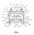
- the pattern of channels comprises channels of different widths and depths. All this is clearly shown in Fig. 2, which is a cross-sectional view from above of the housing part 2 of Fig. 1.
- the channels 12 and 13 (and also the channels 12A and 13A in the housing part 3) have a bottom which is raised with respect to that of the adjoining channels and on which the bends rest so as to obtain a local thermal clamping-in after assembly.
- a wider and deeper channel 16 is present between the channels 12 and 13.
- This channel 16 surrounds the operational segment of the U-shaped tube 6 after assembly, i.e. that portion of the connecting limb 9 that lies between the sides of the electrical windings 10 and 11 that face away from one another.
- the operational segment lies entirely free from the walls and bottom of the channel 16 in this example.
- the width and depth of the channel 16 are preferably such that the operational segment is narrowly enclosed so as to ensure that the air in the channel is stationary as much as possible during operation.
- the distance between the resistance elements and the wall of the channel 16 is, for example, of the order of a few tenths of a millimeter.
- the legs 7, 8 of the tube 6 are guided adjacent their ends 19, 20 through channels 21, 22 that have a slightly greater depth than the channels 12, 13. As a result, the distance between the ends is fixed, which facilitates, for example, the assembly together with other components of a mass flow controller.
- the ends 19, 20 extend through sealing elements (gaskets) 23, 24, which may be made from an elastomer material, to the exterior (cf Fig. 2).
- the channels 12, 13 and 12A, 13A, in which the bends are clamped in may advantageously have a flat bottom, and the channels 21, 22 and 21A, 22A, through which the tube ends are guided, may have a rounded bottom, but the invention is not limited to this.
- the sensor tube 6 is brought into thermal contact with the housing parts 2, 3, i.e. is thermally clamped in, at the areas of its bends when the second housing part 3, which preferably has a pattern of channels corresponding to the pattern of channels of the first housing part 2, is placed on the first housing part 2 during final assembly.
- the housing parts are for this purpose fastened to one another by means of bolts (not shown) which are turned through the housing part 3 into tapped holes in the housing part 2.
- bolts not shown
- the bends of the U-shaped tube 6 may become slightly deformed (flattened).
- the ends 19, 20 of the U-shaped tube 6 will project slightly from the assembled housing parts 2, 3 after assembly.
- the lower portions 30, 30' of the housing parts 2, 3 may be regarded as integrated base portions. They comprise fastening elements 31 and 31' provided with respective bores by means of which the housing parts 2, 3 can be mounted on a base of a mass flow controller.
- the channels in the inner surface 5 of the housing part 3 that correspond to the channels 12, 13, 16, 21, and 22 in the inner surface of the housing part 2 have been given the reference numerals 12A, 13A, 16A, 21A, and 22A.
- the housing parts 2, 3 each comprise, besides the pattern of channels for accommodating the U-shaped sensor tube, also a central cavity 25, 25A. These cavities offer space for providing a connection component such as a connection foil or a connection (printed circuit) board. Said connection component is visible in the construction of Fig. 2. At one side connection wires with the electrical windings are connected thereto, and at the other side thicker wires 27, 28, 29 provide the connection to external circuitry.
- the printed circuit board may be fastened to the legs. In case the sensor tube is comparatively thick, it may be thermally clamped in in the housing 'below' (adjacent the outer side of) the printed circuit board.
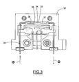
- Fig. 3 is a cross-sectional view of an alternative embodiment of the housing part 2 of Figs. 1 and 2.
- a channel 33 which encloses the operational segment 34 of the U-shaped sensor tube 35 in a location between the electrical resistance elements 36 and 37, is provided with an elevation 38 on which the operational segment 34 rests.
- U-shaped tube denotes any configuration of two legs interconnected by a connecting limb, for example also configurations in which the legs are closer together adjacent their ends than at the connecting limb.
- Figs. 1 to 3 show the clamping-in at the areas of the bends of the U-tube.
- the clamping-in may alternatively be achieved in respective locations between the bends and the ends of the electrical resistance elements, or in respective locations between the bends and the inlet and outlet sides of the legs.
- Fig. 4A is a diagrammatic longitudinal sectional view of a two-part housing 38 for a flow sensor according to the invention
- Fig. 4B is a cross-sectional view taken on the line IV in Fig. 4A
- a housing part 39 is shown, provided with recesses (channels) in which a U-shaped sensor tube 40, provided with two adjoining electrical resistance elements A and B, is accommodated.
- the sensor tube 40 has two bends 41 and 42. These lie free with the portions of the tube 40 provided with the resistance elements A, B in this embodiment (i.e. without making contact with the walls) inside respective recesses (channels) 43, 44 in the inner surface of the housing part 39.
- the tube 40 rests in a shallower recess 45 in the inner surface.
- a shallower recess is also present in the housing counterpart 39' (Fig. 4B), so that the tube 40 will be locally clamped in between the housing parts when the latter are assembled together, and heat from the tube can be directly transferred to the housing, as is desired for improving the CT method.
- Fig. 4A further shows that the U-shaped tube 40 has legs 46, 47 which are accommodated in shallow recesses 48, 49 at the sides of the bends 41, 42 remote from the respective resistance elements A, B, such that the legs are thermally clamped in below the bends when the housing part 39 is joined to a housing counterpart 39' (Fig. 4B), with the result that external temperature gradients cannot reach the operational segment of the tube 40, which lies between the sides of the resistance elements A and B that face away from one another.
- the sensor tube in Figs. 1 to 3 is thermally clamped in at the areas of the bends.
- the housing 38 comprising the housing parts 39 and 39' rests on a base 61.
- the legs 46, 47 of the tube 40 which extend freely through a central cavity 62, are passed to the exterior through ducts 50, 51 in the base 61.
- the base 61 may be a separate component or a component integral with the housing parts 39, 39'.
- the base 61 may be provided with elevations at its inside on which a printed circuit board with the necessary circuits may rest.
- Fig. 5A which is a diagrammatic longitudinal sectional view of a housing for a flow sensor according to the invention
- Fig. 5B which is a cross-sectional view taken on the line V in Fig. 5A
- the legs 52, 53 of the U-shaped tube 54 are clamped in over a greater length in that the legs 52, 53 are held in (shallow) channels 55, 56 which are longer than the channels 48, 49 in the construction of Figs. 4A, 4B.
- the channels 55, 56 in the inner surface of the housing part 60 extend from the lower sides of the bends right through to the base 59.
- a thermal clamping-in of the sensor tube 54 may again be provided between the resistance elements A' and B' also in this construction.
- U-shaped tube denotes any configuration of two legs interconnected by a connecting limb, for example also configurations in which the legs are closer together adjacent their ends than at the connecting limb.
- Figs. 1 to 3 show a clamping-in at the areas of the bends of the U-tube.
- the clamping-in may alternatively be provided in respective locations between the bends and the ends of the electrical resistance elements, or in respective locations between the bends and the inlet and outlet sides of the legs.
- the tube is preferably thermally clamped in there where the temperature profile just ends.
- a tube's clamping-in is dependent on the heat profile of the sensor (or in fact the windings thereof).
- FIG. 1 For specific aspects of the flow sensor according to the invention are: there are two windings (resistance elements) which are located next to one another on the connecting limb, preferably symmetrically with respect to the center of the connecting limb.
- the housing parts form a housing wherein the connecting leg lies uppermost during operation, such that a temperature gradient in the base (against which the sensor is tightly screwed) is evened out before the operational part of the sensor is reached.
- local clamping in denotes clamping in over a portion of the relevant available path, for example over a portion of the path between the inlet side of the sensor tube and the upstream resistance element or over a portion of the path between the outlet side of the sensor tube and the downstream resistance element.
Landscapes
- Physics & Mathematics (AREA)
- Fluid Mechanics (AREA)
- General Physics & Mathematics (AREA)
- Measuring Volume Flow (AREA)
- Control Of Combustion (AREA)
Abstract
Description
- The invention relates to a flow sensor of the thermal type having a U-shaped sensor tube with two legs and a connecting limb with two adjoining electrical resistance elements, and with a housing, which sensor tube has an inlet side where flow enters and an outlet side where flow exits.
- A flow sensor as described above is known from
WO 03058180 - Thermal flowmeters with flow sensors having a capillary tube utilize the fact that heat transfer from the tube wall to a fluid (gas or liquid) flowing in the tube is a function of the mass flow rate, the difference between the fluid temperature and the wall temperature, and the specific heat capacity of the fluid. A wide variety of flow sensor configurations is used in mass flow controllers. A particular type of construction, for example, involves the use of a stainless steel flow tube with two or more resistance elements in thermally conductive contact with the flow tube. The resistance elements are typically manufactured from a material that has a high temperature coefficient of resistance. Each of the elements can act as a heater, as a temperature detector, or as both. At least one resistance element (the heater) is energized with an electric current so as to supply heat to the flow of fluid through the tube. When two heaters are energized with a constant power, the mass flow rate of the fluid through the tube can be derived from the temperature differences between the resistance elements. In an alternative method, a first resistance element in a first position acts as a heater and as a temperature detector, and a second resistance element located in a second position upstream of the first position acts as a temperature detector. A control circuit serves to keep the temperature difference between the resistance elements at a fixed, predetermined value, the mass flow rate of the fluid flowing through the tube then being derived from data of the control circuit. This measuring method is known as the Constant Temperature (CT) method.
- The invention, however, is also suitable for use with the TB (Thermal Balancing) method as described in
EP 1 477 779 . - It is a problem with the measuring methods and systems mentioned above that inaccuracies in the measuring signal may occur in the case of a comparatively low flow rate through the tube. The inventors ascribe this to the fact that thermal mass flowmeters are often used in surroundings where temperature gradients may arise across (portions of) the sensor tube and/or across the resistance elements. In the construction known from
WO 03058180 - The invention has for its object to provide a flow sensor of the type mentioned in the opening paragraph which opposes the influence of external temperature gradients so as to achieve that no or at least as small as possible a temperature gradient arises not only across the operational segment of the tube, i.e. the portion situated between the sides of the resistance elements that face away from one another, but also across the legs (and the bends joining the legs to the connecting limb) during operation.
- According to the invention, a flow sensor of the kind mentioned in the opening paragraph is for this purpose characterized in that the housing comprises a first and a second housing part of a thermally well-conducting material, each with an inner surface provided with cavities and with an outer surface, which housing parts are placed with their inner surfaces against each other, while the U-shaped sensor tube has a main surface that extends parallel to the inner surfaces, and the housing parts surround the connecting limb and the legs of the U-shaped sensor tube wherein said sensor tube is locally thermally clamped in between the housing parts in a first location situated between its inlet side and the upstream resistance element and is locally thermally clamped in between the housing parts in a second location situated between its outlet side and the downstream resistance element.
- It is found that the problem of temperature gradients arising across (portions of) the sensor tube can be solved to a high degree in that the sensor tube is locally thermally clamped in between two housing parts made of a thermally well-conducting material, such that the housing surrounds the connecting limb with the two electrical resistance elements, the bends, and the legs of the sensor tube. To achieve a good operation, a preferred embodiment is characterized in that the U-shaped sensor tube lies free between the housing parts between its inlet side and the upstream resistive element and between its outlet side and the downstream resistive element except for the locations where it is thermally clamped in.
- An embodiment which has the advantage of an effective thermal clamping-in is characterized in that the cavities in the inner surface of the first housing part and the cavities in the inner surface of the second housing part constitute channels that correspond with one another two-by-two, said channels being shallower in those locations where the sensor tube is thermally clamped in than they are elsewhere.
- The portion of the sensor tube lying between the portions of the electrical resistance elements that face away from one another (i.e. the operational segment of the sensor tube) can be located in mutually facing channels in the inner surfaces of dimensions such that the tube (with windings) lies free of the housing parts.
- If the cavities (channels) are so wide that a flow of air can occur around the operational tube segment during operation (denoted the chimney effect), however, it may be advisable to provide polystyrene foam in the space surrounding this tube portion. A disadvantage of this is, however, that it is found to counteract a fast operation of the sensor.
- A further embodiment is accordingly characterized in that the connecting limb of the U-shaped sensor tube with the resistance elements provided thereon is narrowly enclosed by the mutually facing cavities, i.e. channels, in the inner surfaces of the housing parts.
- The fact that the channels narrowly enclose the tube with windings serves to ensure that the air around the tube is stationary during operation, so that no heat flow around the sensor (giving rise to the so-termed chimney effect) will occur.
- An embodiment of the clamping-in is characterized in that the U-shaped sensor tube is locally thermally clamped in between the housing parts adjacent or at the transitions from the legs to the connecting limb (i.e. the bends). In other words: the clamping-in of the U-shaped sensor tube takes place at the areas of the bends or adjacent the bends. If the clamping-in takes place adjacent the bends, this may be at the sides facing the operational segment, but preferably such clamping-in takes place at the sides of the bends facing away from the operational segment.
- Another embodiment of the clamping-in is characterized in that the U-shaped sensor tube is locally thermally clamped in between the housing parts adjacent its inlet side and its outlet side. The occurrence of temperature gradients adjacent the inlet and outlet sides of the sensor tube is thus avoided. This is important especially where thicker tubes are used.
- An additional problem in measuring systems operating according to the CT principle is that an (undesirable) dip in the measuring signal occurs when there is a comparatively low rate of flow through the tube.
- To prevent this dip, a further embodiment is characterized in that in addition the connecting limb of the U-shaped sensor tube is thermally clamped in between the housing parts in a location between the two electrical resistance elements. This embodiment is of special importance in cases in which thermal clamping-in takes place in or adjacent the bends, in particular in combination with resistance elements of unequal values.
- The provision of a thermal contact between the tube and the housing parts in a location between the two resistance elements ensures that in this location any heat generated by the heater and flowing through the tube wall is discharged towards the housing, so that it cannot reach the upstream temperature detector, i.e. cannot adversely influence the latter. The dip mentioned above is caused by such undesirable influences.
- An additional feature of the invention is the characteristic that each housing part comprises a base portion, and that the legs of the sensor tube are passed to the exterior through cavities arranged two-by-two opposite one another in said base portions. This embodiment renders possible an automated manufacture of the sensor as well as an automated placement of the sensor on a base construction of a mass flow controller.
- A further step towards automation is characterized in that the first and the second housing part are manufactured from a metal alloy by means of die casting. Die casting of the housing parts renders any grinding and/or cutting of the housing parts unnecessary.
- Some embodiments of the invention will now be explained in more detail by way of example with reference to the drawings, in which:
- Fig. 1
- is an exploded perspective view of the sensor tube and the two housing parts of a flow sensor according to the invention;
- Fig. 2
- is a cross-sectional view of one of the housing parts of Fig. 1 with the sensor tube of Fig. 1 mounted therein;
- Fig. 3
- is a cross-sectional view of an alternative embodiment of a housing part for a flow sensor according to the invention;
- Fig. 4A
- is a diagrammatic longitudinal sectional view of a two-
part housing 38 for a flow sensor according to the invention; - Fig. 4B
- is a cross-sectional view taken on the line IV in Fig. 4A;
- Fig. 5A
- is a longitudinal sectional view of an alternative housing for a flow sensor according to the invention; and
- Fig. 5B
- is a cross-sectional view taken on the line V in Fig. 5A.
- The exploded view of Fig. 1 shows the main components of a flow sensor 1 according to the invention. The flow sensor 1 comprises a
first housing part 2 and asecond housing part 3. Thehousing parts parts inner surfaces 4 and 5 thereof lie on top of one another. They are centered by means of mortise and tenon joints. In the present case the tenons are formed byridges housing part 2, and the mortises are formed by the openings in thehousing part 3 that match the ridges. This renders it possible to carry out an automation process whereby the housing parts are supplied on a tray, the sensor tube is placed in one of the housing parts, and the housing parts are snapped into one another by means of a robot. -
Reference numeral 6 denotes a sensor tube. This is a single-part capillary tube of stainless steel in this example with an external diameter of 0.3 mm and an internal diameter of 0.2 mm. Thetube 6 is bent into a U-shape and haslegs member 9. Theleg 7 has an inlet side for receiving the flow Φ to be measured and theleg 8 has an outlet side for the flow Φ to be measured. The connectingmember 9 supportsresistance elements member 9. The invention, however, is not limited to this embodiment. During assembly thesensor tube 6 is laid with itselectrical resistance elements housing part 2. The main surface of the U-shaped tube is thus parallel to the inner surface of the housing part 2 (and after assembly also to the inner surface of the housing part 3). The pattern of channels in thehousing part 2 follows the U-shape of thetube 6. The pattern of channels comprises channels of different widths and depths. All this is clearly shown in Fig. 2, which is a cross-sectional view from above of thehousing part 2 of Fig. 1. - The
channels bends channels 12 and 13 (and also thechannels deeper channel 16 is present between thechannels channel 16 surrounds the operational segment of theU-shaped tube 6 after assembly, i.e. that portion of the connectinglimb 9 that lies between the sides of theelectrical windings channel 16 in this example. The width and depth of thechannel 16 are preferably such that the operational segment is narrowly enclosed so as to ensure that the air in the channel is stationary as much as possible during operation. The distance between the resistance elements and the wall of thechannel 16 is, for example, of the order of a few tenths of a millimeter. Thelegs tube 6 are guided adjacent theirends channels channels - The
channels channels - The
sensor tube 6 is brought into thermal contact with thehousing parts second housing part 3, which preferably has a pattern of channels corresponding to the pattern of channels of thefirst housing part 2, is placed on thefirst housing part 2 during final assembly. The housing parts are for this purpose fastened to one another by means of bolts (not shown) which are turned through thehousing part 3 into tapped holes in thehousing part 2. During clamping, the bends of theU-shaped tube 6 may become slightly deformed (flattened). The ends 19, 20 of theU-shaped tube 6 will project slightly from the assembledhousing parts channels channels 21 A, 22A, they have a fixed mutual distance at the exterior of the housing, so that the sensor 1 can be readily mounted on a base unit of a mass flow controller. Thelower portions 30, 30' of thehousing parts fastening elements 31 and 31' provided with respective bores by means of which thehousing parts inner surface 5 of thehousing part 3 that correspond to thechannels reference numerals - The
housing parts central cavity thicker wires - Fig. 3 is a cross-sectional view of an alternative embodiment of the
housing part 2 of Figs. 1 and 2. - The difference with the fig. 2 construction is that in this case a
channel 33, which encloses theoperational segment 34 of theU-shaped sensor tube 35 in a location between theelectrical resistance elements elevation 38 on which theoperational segment 34 rests. When thehousing part 32 is assembled together with a housing counterpart having a corresponding pattern of channels (not shown), thetube 35 will be thermally clamped in at a location between theelectrical resistance elements - In this manner heat is transferred from the tube to the housing between the
windings housing part 32 and that of thehousing counterpart 33 to be closer to thesensor 36 than to the heater 37 (preferably as close as possible to the sensor 36) so as to prevent any undesirable influence of theheater 37 on thesensor 36. All this is explained further with reference to Fig. 4. - The expression "U-shaped tube" denotes any configuration of two legs interconnected by a connecting limb, for example also configurations in which the legs are closer together adjacent their ends than at the connecting limb.
- Figs. 1 to 3 show the clamping-in at the areas of the bends of the U-tube. The clamping-in may alternatively be achieved in respective locations between the bends and the ends of the electrical resistance elements, or in respective locations between the bends and the inlet and outlet sides of the legs.
- Fig. 4A is a diagrammatic longitudinal sectional view of a two-
part housing 38 for a flow sensor according to the invention, and Fig. 4B is a cross-sectional view taken on the line IV in Fig. 4A. Ahousing part 39 is shown, provided with recesses (channels) in which aU-shaped sensor tube 40, provided with two adjoining electrical resistance elements A and B, is accommodated. Thesensor tube 40 has twobends tube 40 provided with the resistance elements A, B in this embodiment (i.e. without making contact with the walls) inside respective recesses (channels) 43, 44 in the inner surface of thehousing part 39. Between therecesses tube 40 rests in ashallower recess 45 in the inner surface. Such a shallower recess is also present in the housing counterpart 39' (Fig. 4B), so that thetube 40 will be locally clamped in between the housing parts when the latter are assembled together, and heat from the tube can be directly transferred to the housing, as is desired for improving the CT method. - Fig. 4A further shows that the
U-shaped tube 40 haslegs 46, 47 which are accommodated inshallow recesses bends housing part 39 is joined to a housing counterpart 39' (Fig. 4B), with the result that external temperature gradients cannot reach the operational segment of thetube 40, which lies between the sides of the resistance elements A and B that face away from one another. For comparison: the sensor tube in Figs. 1 to 3 is thermally clamped in at the areas of the bends. - As Figs. 4A and 4B show, the
housing 38 comprising thehousing parts 39 and 39' rests on abase 61. Thelegs 46, 47 of thetube 40, which extend freely through acentral cavity 62, are passed to the exterior throughducts base 61. The base 61 may be a separate component or a component integral with thehousing parts 39, 39'. The base 61 may be provided with elevations at its inside on which a printed circuit board with the necessary circuits may rest. - Fig. 5A, which is a diagrammatic longitudinal sectional view of a housing for a flow sensor according to the invention, and Fig. 5B, which is a cross-sectional view taken on the line V in Fig. 5A, present an alternative to the construction shown in Figs. 4A and 4B, in which alternative the
legs U-shaped tube 54 are clamped in over a greater length in that thelegs channels channels - In Fig. 5A, the
channels housing part 60 extend from the lower sides of the bends right through to thebase 59. As in the construction of Fig. 4, a thermal clamping-in of thesensor tube 54 may again be provided between the resistance elements A' and B' also in this construction. - The expression "U-shaped tube" denotes any configuration of two legs interconnected by a connecting limb, for example also configurations in which the legs are closer together adjacent their ends than at the connecting limb.
- Figs. 1 to 3 show a clamping-in at the areas of the bends of the U-tube. The clamping-in may alternatively be provided in respective locations between the bends and the ends of the electrical resistance elements, or in respective locations between the bends and the inlet and outlet sides of the legs.
- Generally speaking, the tube is preferably thermally clamped in there where the temperature profile just ends. In other words: a tube's clamping-in is dependent on the heat profile of the sensor (or in fact the windings thereof).
- Further specific aspects of the flow sensor according to the invention are: there are two windings (resistance elements) which are located next to one another on the connecting limb, preferably symmetrically with respect to the center of the connecting limb. The housing parts form a housing wherein the connecting leg lies uppermost during operation, such that a temperature gradient in the base (against which the sensor is tightly screwed) is evened out before the operational part of the sensor is reached.
- The expression "local clamping in" herein denotes clamping in over a portion of the relevant available path, for example over a portion of the path between the inlet side of the sensor tube and the upstream resistance element or over a portion of the path between the outlet side of the sensor tube and the downstream resistance element.
Claims (10)
- A flow sensor (1) of the thermal type having a U-shaped sensor tube (6) with two legs (7,8) and a connecting limb (9) with two adjoining electrical resistance elements (10,11), and with a housing, which sensor tube (6) has an inlet side (19) where flow enters and an outlet side (20) where flow exits,
characterized in that the housing comprises a first and a second housing part (2,3) of a thermally well-conducting material, each with an inner surface (4,5) provided with cavities and with an outer surface, which housing parts are placed with their inner surfaces (4,5) against each other, while the U-shaped sensor tube (6) has a main surface that extends parallel to the inner surfaces (4,5), and the housing parts (2,3) surround the connecting limb (9) and the legs (7,8) of the U-shaped sensor tube (6) wherein said sensor tube (6) is locally thermally clamped in between the housing parts (2,3) in a first location situated between its inlet side (19) and the upstream resistance element (10) and is locally thermally clamped in between the housing parts (2,3) in a second location situated between its outlet side (20) and the downstream resistance element (11). - A flow sensor as claimed in claim 1,
characterized in that the U-shaped sensor tube (6) makes no contact with the housing parts (2,3) between its inlet side (19) and the upstream resistance element (10) and between its outlet side (20) and the downstream resistance element (11), except for those locations where it is thermally clamped in. - A flow sensor as claimed in claim 1,
characterized in that the cavities in the inner surface (4) of the first housing part (2) and the cavities in the inner surface (5) of the second housing part (3) constitute channels that correspond with one another two-by-two, said channels being shallower in those locations where the sensor tube (6) is thermally clamped in than they are elsewhere. - A flow sensor as claimed in claim 1, 2, or 3,
characterized in that the connecting limb (9) of the U-shaped sensor tube (6) with the resistance elements (10,11) provided thereon is narrowly enclosed by the mutually facing cavities, i.e. channels, in the inner surfaces of the housing parts (2,3). - A flow sensor as claimed in claim 1,
characterized in that the U-shaped sensor tube (6) is locally thermally clamped in between the housing parts (2,3) adjacent or at the transitions (14,15) from the legs (7,8) to the connecting limb (9) (the bends). - A flow sensor as claimed in claim 1,
characterized in that the U-shaped sensor tube (6) is locally thermally clamped in between the housing parts (2,3) adjacent its inlet and its outlet side (19,20). - A flow sensor as claimed in claim 1,
characterized in that in addition the connecting limb (9) of the U-shaped sensor tube (6) is thermally clamped in between the housing parts (2,3) in a location between the two electrical resistance elements (10,11). - A flow sensor as claimed in claim 7, wherein the U-shaped sensor tube (6) is
locally thermally clamped in adjacent or at the transitions (14,15) between the legs (7.8) and the connecting limb (9). - A flow sensor as claimed in claim 1,
characterized in that each housing part (2,3) comprises a base portion (30, 301), and in that the legs (7,8) of the sensor tube are passed to the exterior through cavities (21,22; 21A,22A) arranged two-by-two opposite one another in said base portions. - A flow sensor as claimed in claim 1,
characterized in that the first and the second housing part (2,3) are manufactured from a metal alloy by means of die casting.
Applications Claiming Priority (1)
| Application Number | Priority Date | Filing Date | Title |
|---|---|---|---|
| NL1032007A NL1032007C2 (en) | 2006-06-14 | 2006-06-14 | Thermal sensor flow sensor. |
Publications (2)
| Publication Number | Publication Date |
|---|---|
| EP1867962A1 true EP1867962A1 (en) | 2007-12-19 |
| EP1867962B1 EP1867962B1 (en) | 2010-03-17 |
Family
ID=37685940
Family Applications (1)
| Application Number | Title | Priority Date | Filing Date |
|---|---|---|---|
| EP07075369A Not-in-force EP1867962B1 (en) | 2006-06-14 | 2007-05-15 | Flow sensor of the thermal type |
Country Status (8)
| Country | Link |
|---|---|
| US (1) | US7437928B2 (en) |
| EP (1) | EP1867962B1 (en) |
| JP (1) | JP2007333735A (en) |
| AT (1) | ATE461432T1 (en) |
| DE (1) | DE602007005306D1 (en) |
| DK (1) | DK1867962T3 (en) |
| ES (1) | ES2340724T3 (en) |
| NL (1) | NL1032007C2 (en) |
Cited By (7)
| Publication number | Priority date | Publication date | Assignee | Title |
|---|---|---|---|---|
| WO2010045172A1 (en) * | 2008-10-13 | 2010-04-22 | Advanced Energy Industries, Inc. | Mass flow controller and method of operating the same |
| NL2011975C2 (en) * | 2013-12-17 | 2015-06-18 | Berkin Bv | FLOW MEASURING DEVICE OF THE THERMAL TYPE. |
| WO2015112009A1 (en) | 2014-01-23 | 2015-07-30 | Berkin B.V. | Flow measurement system and method for determining at least one property of a medium |
| CN106768113A (en) * | 2016-12-09 | 2017-05-31 | 北京七星华创电子股份有限公司 | A kind of fluid conveys measurement apparatus |
| WO2019235928A1 (en) | 2018-06-08 | 2019-12-12 | Berkin B.V. | Pressure-insensitive thermal type flow meter |
| FR3096452A1 (en) * | 2019-05-22 | 2020-11-27 | Buerkert Werke Gmbh & Co. Kg | Mass flow sensor assembly and method of manufacturing a mass flow sensor assembly |
| WO2022025762A1 (en) | 2020-07-30 | 2022-02-03 | Berkin B.V. | Thermal-type flow sensor with a thermally conductive frame element in the form of a printed circuit board (pcb) |
Families Citing this family (5)
| Publication number | Priority date | Publication date | Assignee | Title |
|---|---|---|---|---|
| US9791307B2 (en) * | 2015-03-06 | 2017-10-17 | Alicat Scientific, Inc. | Systems and methods for detecting flow of a fluid |
| JP2017101955A (en) * | 2015-11-30 | 2017-06-08 | アズビル株式会社 | Measuring apparatus and method for manufacturing measuring apparatus |
| KR102403432B1 (en) * | 2016-03-11 | 2022-05-30 | 히타치 긴조쿠 가부시키가이샤 | A thermal mass flow sensor, a method for manufacturing the thermal mass flow sensor, and a thermal mass flow meter using the thermal mass flow sensor |
| WO2018180387A1 (en) * | 2017-03-30 | 2018-10-04 | 株式会社フジキン | Mass flow sensor, mass flow meter provided with mass flow sensor, and mass flow controller provided with mass flow sensor |
| JP7467887B2 (en) * | 2019-11-01 | 2024-04-16 | オムロン株式会社 | Plant Biosensor |
Citations (5)
| Publication number | Priority date | Publication date | Assignee | Title |
|---|---|---|---|---|
| US4517838A (en) * | 1982-11-12 | 1985-05-21 | Ohkura Electric Co., Ltd. | Thermal mass flow meter |
| US4815280A (en) * | 1986-05-27 | 1989-03-28 | Stec Inc. | Thermal flow meter |
| US5191793A (en) | 1984-03-12 | 1993-03-09 | Tylan Corporation | Fluid mass flow meter device with reduced attitude sensitivity |
| WO2003058180A1 (en) | 2001-12-21 | 2003-07-17 | Mks Instruments, Inc. | Apparatus and method for thermal management of a mass flow controller |
| EP1477779A1 (en) | 2003-05-13 | 2004-11-17 | Berkin B.V. | Mass flowmeter |
Family Cites Families (3)
| Publication number | Priority date | Publication date | Assignee | Title |
|---|---|---|---|---|
| JP3047184B2 (en) * | 1989-11-27 | 2000-05-29 | 株式会社エステック | Mass flow meter |
| WO1991019959A1 (en) * | 1990-06-14 | 1991-12-26 | Unit Instruments, Inc. | Thermal mass flow sensor |
| US5792952A (en) * | 1996-05-23 | 1998-08-11 | Varian Associates, Inc. | Fluid thermal mass flow sensor |
-
2006
- 2006-06-14 NL NL1032007A patent/NL1032007C2/en not_active IP Right Cessation
-
2007
- 2007-05-15 AT AT07075369T patent/ATE461432T1/en active
- 2007-05-15 EP EP07075369A patent/EP1867962B1/en not_active Not-in-force
- 2007-05-15 DK DK07075369.4T patent/DK1867962T3/en active
- 2007-05-15 DE DE602007005306T patent/DE602007005306D1/en active Active
- 2007-05-15 ES ES07075369T patent/ES2340724T3/en active Active
- 2007-05-18 US US11/798,983 patent/US7437928B2/en active Active
- 2007-05-31 JP JP2007145880A patent/JP2007333735A/en active Pending
Patent Citations (5)
| Publication number | Priority date | Publication date | Assignee | Title |
|---|---|---|---|---|
| US4517838A (en) * | 1982-11-12 | 1985-05-21 | Ohkura Electric Co., Ltd. | Thermal mass flow meter |
| US5191793A (en) | 1984-03-12 | 1993-03-09 | Tylan Corporation | Fluid mass flow meter device with reduced attitude sensitivity |
| US4815280A (en) * | 1986-05-27 | 1989-03-28 | Stec Inc. | Thermal flow meter |
| WO2003058180A1 (en) | 2001-12-21 | 2003-07-17 | Mks Instruments, Inc. | Apparatus and method for thermal management of a mass flow controller |
| EP1477779A1 (en) | 2003-05-13 | 2004-11-17 | Berkin B.V. | Mass flowmeter |
Cited By (13)
| Publication number | Priority date | Publication date | Assignee | Title |
|---|---|---|---|---|
| WO2010045172A1 (en) * | 2008-10-13 | 2010-04-22 | Advanced Energy Industries, Inc. | Mass flow controller and method of operating the same |
| NL2011975C2 (en) * | 2013-12-17 | 2015-06-18 | Berkin Bv | FLOW MEASURING DEVICE OF THE THERMAL TYPE. |
| WO2015093941A1 (en) * | 2013-12-17 | 2015-06-25 | Berkin B.V. | Thermal type flow meter |
| US10302475B2 (en) | 2013-12-17 | 2019-05-28 | Berkin B.V. | Thermal flow meter having a cover element that surrounds an insulated housing |
| US10648935B2 (en) | 2014-01-23 | 2020-05-12 | Berkin B.V. | Flow measurement system and method for determining at least one property of a medium |
| WO2015112009A1 (en) | 2014-01-23 | 2015-07-30 | Berkin B.V. | Flow measurement system and method for determining at least one property of a medium |
| CN106768113A (en) * | 2016-12-09 | 2017-05-31 | 北京七星华创电子股份有限公司 | A kind of fluid conveys measurement apparatus |
| WO2019235928A1 (en) | 2018-06-08 | 2019-12-12 | Berkin B.V. | Pressure-insensitive thermal type flow meter |
| FR3096452A1 (en) * | 2019-05-22 | 2020-11-27 | Buerkert Werke Gmbh & Co. Kg | Mass flow sensor assembly and method of manufacturing a mass flow sensor assembly |
| US11821776B2 (en) | 2019-05-22 | 2023-11-21 | Buerkert Werke Gmbh & Co. Kg | Mass flow sensor assembly and method of manufacturing a mass flow sensor assembly |
| DE102020112464B4 (en) | 2019-05-22 | 2024-03-21 | Burkert S.A.S. | Mass flow sensor assembly and method for producing a mass flow sensor assembly |
| WO2022025762A1 (en) | 2020-07-30 | 2022-02-03 | Berkin B.V. | Thermal-type flow sensor with a thermally conductive frame element in the form of a printed circuit board (pcb) |
| NL2026167B1 (en) | 2020-07-30 | 2022-04-08 | Berkin Bv | Thermal-type flow sensor with a thermally conductive frame element in the form of a printed circuit board (PCB) |
Also Published As
| Publication number | Publication date |
|---|---|
| US20070295079A1 (en) | 2007-12-27 |
| JP2007333735A (en) | 2007-12-27 |
| ES2340724T3 (en) | 2010-06-08 |
| NL1032007C2 (en) | 2007-12-17 |
| US7437928B2 (en) | 2008-10-21 |
| EP1867962B1 (en) | 2010-03-17 |
| DE602007005306D1 (en) | 2010-04-29 |
| DK1867962T3 (en) | 2010-06-28 |
| ATE461432T1 (en) | 2010-04-15 |
Similar Documents
| Publication | Publication Date | Title |
|---|---|---|
| US7437928B2 (en) | Flow sensor of the thermal type | |
| US6971274B2 (en) | Immersible thermal mass flow meter | |
| AU2008306946B2 (en) | Heating device with an integrated thermoblock for a beverage preparation machine | |
| US7059184B2 (en) | Split-flow-type flow sensor device | |
| CN202757246U (en) | Thick-film heater | |
| US9696191B2 (en) | Thermal, flow measuring device | |
| JP3953535B2 (en) | Apparatus for measuring the mass of a fluid medium | |
| CN111201423B (en) | Miniature flow sensor with shield | |
| CN110192087B (en) | Housing for flow measuring device and flow measuring device with such housing | |
| KR102277609B1 (en) | Thermal type flow meter | |
| US20230134684A1 (en) | Modular heater assembly with interchangeable auxiliary sensing junctions | |
| JP4537067B2 (en) | Apparatus and method for thermal management of mass flow controller | |
| TWI266865B (en) | Apparatus and method for thermal isolation of thermal mass flow sensor | |
| WO2018160620A1 (en) | Breath sensor | |
| WO2018116641A1 (en) | Gas sensor | |
| EP0927617A1 (en) | Hot runner nozzle | |
| US20200348160A1 (en) | Flow laminator | |
| JP5833403B2 (en) | Fluid mechanism and support member constituting the fluid mechanism | |
| TWI261666B (en) | Apparatus and method for thermal dissipation in a thermal mass flow sensor | |
| US12416531B2 (en) | Temperature sensor, temperature detection device and image formation device | |
| KR200479937Y1 (en) | Sensor device for Heating Apparatus | |
| EP3183525A1 (en) | Continuous-flow water heating assembly and production method | |
| JP6082082B2 (en) | Fluid mechanism and support member constituting the fluid mechanism | |
| EP3985314A1 (en) | Controller and actuator for a heat exchanger valve | |
| US7880482B2 (en) | Sensor mechanism and method for the production thereof |
Legal Events
| Date | Code | Title | Description |
|---|---|---|---|
| PUAI | Public reference made under article 153(3) epc to a published international application that has entered the european phase |
Free format text: ORIGINAL CODE: 0009012 |
|
| AK | Designated contracting states |
Kind code of ref document: A1 Designated state(s): AT BE BG CH CY CZ DE DK EE ES FI FR GB GR HU IE IS IT LI LT LU LV MC MT NL PL PT RO SE SI SK TR |
|
| AX | Request for extension of the european patent |
Extension state: AL BA HR MK YU |
|
| 17P | Request for examination filed |
Effective date: 20080508 |
|
| 17Q | First examination report despatched |
Effective date: 20080630 |
|
| AKX | Designation fees paid |
Designated state(s): AT BE BG CH CY CZ DE DK EE ES FI FR GB GR HU IE IS IT LI LT LU LV MC MT NL PL PT RO SE SI SK TR |
|
| GRAP | Despatch of communication of intention to grant a patent |
Free format text: ORIGINAL CODE: EPIDOSNIGR1 |
|
| GRAS | Grant fee paid |
Free format text: ORIGINAL CODE: EPIDOSNIGR3 |
|
| GRAA | (expected) grant |
Free format text: ORIGINAL CODE: 0009210 |
|
| AK | Designated contracting states |
Kind code of ref document: B1 Designated state(s): AT BE BG CH CY CZ DE DK EE ES FI FR GB GR HU IE IS IT LI LT LU LV MC MT NL PL PT RO SE SI SK TR |
|
| REG | Reference to a national code |
Ref country code: GB Ref legal event code: FG4D |
|
| REG | Reference to a national code |
Ref country code: CH Ref legal event code: EP |
|
| REG | Reference to a national code |
Ref country code: IE Ref legal event code: FG4D |
|
| REG | Reference to a national code |
Ref country code: CH Ref legal event code: NV Representative=s name: ISLER & PEDRAZZINI AG |
|
| REF | Corresponds to: |
Ref document number: 602007005306 Country of ref document: DE Date of ref document: 20100429 Kind code of ref document: P |
|
| REG | Reference to a national code |
Ref country code: NL Ref legal event code: T3 |
|
| REG | Reference to a national code |
Ref country code: SE Ref legal event code: TRGR |
|
| REG | Reference to a national code |
Ref country code: ES Ref legal event code: FG2A Ref document number: 2340724 Country of ref document: ES Kind code of ref document: T3 |
|
| REG | Reference to a national code |
Ref country code: DK Ref legal event code: T3 |
|
| PG25 | Lapsed in a contracting state [announced via postgrant information from national office to epo] |
Ref country code: LT Free format text: LAPSE BECAUSE OF FAILURE TO SUBMIT A TRANSLATION OF THE DESCRIPTION OR TO PAY THE FEE WITHIN THE PRESCRIBED TIME-LIMIT Effective date: 20100317 |
|
| LTIE | Lt: invalidation of european patent or patent extension |
Effective date: 20100317 |
|
| PG25 | Lapsed in a contracting state [announced via postgrant information from national office to epo] |
Ref country code: SI Free format text: LAPSE BECAUSE OF FAILURE TO SUBMIT A TRANSLATION OF THE DESCRIPTION OR TO PAY THE FEE WITHIN THE PRESCRIBED TIME-LIMIT Effective date: 20100317 Ref country code: PL Free format text: LAPSE BECAUSE OF FAILURE TO SUBMIT A TRANSLATION OF THE DESCRIPTION OR TO PAY THE FEE WITHIN THE PRESCRIBED TIME-LIMIT Effective date: 20100317 Ref country code: FI Free format text: LAPSE BECAUSE OF FAILURE TO SUBMIT A TRANSLATION OF THE DESCRIPTION OR TO PAY THE FEE WITHIN THE PRESCRIBED TIME-LIMIT Effective date: 20100317 Ref country code: LV Free format text: LAPSE BECAUSE OF FAILURE TO SUBMIT A TRANSLATION OF THE DESCRIPTION OR TO PAY THE FEE WITHIN THE PRESCRIBED TIME-LIMIT Effective date: 20100317 |
|
| PG25 | Lapsed in a contracting state [announced via postgrant information from national office to epo] |
Ref country code: RO Free format text: LAPSE BECAUSE OF FAILURE TO SUBMIT A TRANSLATION OF THE DESCRIPTION OR TO PAY THE FEE WITHIN THE PRESCRIBED TIME-LIMIT Effective date: 20100317 Ref country code: GR Free format text: LAPSE BECAUSE OF FAILURE TO SUBMIT A TRANSLATION OF THE DESCRIPTION OR TO PAY THE FEE WITHIN THE PRESCRIBED TIME-LIMIT Effective date: 20100618 Ref country code: EE Free format text: LAPSE BECAUSE OF FAILURE TO SUBMIT A TRANSLATION OF THE DESCRIPTION OR TO PAY THE FEE WITHIN THE PRESCRIBED TIME-LIMIT Effective date: 20100317 Ref country code: CY Free format text: LAPSE BECAUSE OF FAILURE TO SUBMIT A TRANSLATION OF THE DESCRIPTION OR TO PAY THE FEE WITHIN THE PRESCRIBED TIME-LIMIT Effective date: 20100317 |
|
| PG25 | Lapsed in a contracting state [announced via postgrant information from national office to epo] |
Ref country code: CZ Free format text: LAPSE BECAUSE OF FAILURE TO SUBMIT A TRANSLATION OF THE DESCRIPTION OR TO PAY THE FEE WITHIN THE PRESCRIBED TIME-LIMIT Effective date: 20100317 Ref country code: BG Free format text: LAPSE BECAUSE OF FAILURE TO SUBMIT A TRANSLATION OF THE DESCRIPTION OR TO PAY THE FEE WITHIN THE PRESCRIBED TIME-LIMIT Effective date: 20100617 Ref country code: IS Free format text: LAPSE BECAUSE OF FAILURE TO SUBMIT A TRANSLATION OF THE DESCRIPTION OR TO PAY THE FEE WITHIN THE PRESCRIBED TIME-LIMIT Effective date: 20100717 Ref country code: SK Free format text: LAPSE BECAUSE OF FAILURE TO SUBMIT A TRANSLATION OF THE DESCRIPTION OR TO PAY THE FEE WITHIN THE PRESCRIBED TIME-LIMIT Effective date: 20100317 |
|
| PG25 | Lapsed in a contracting state [announced via postgrant information from national office to epo] |
Ref country code: MC Free format text: LAPSE BECAUSE OF NON-PAYMENT OF DUE FEES Effective date: 20100531 |
|
| PLBE | No opposition filed within time limit |
Free format text: ORIGINAL CODE: 0009261 |
|
| STAA | Information on the status of an ep patent application or granted ep patent |
Free format text: STATUS: NO OPPOSITION FILED WITHIN TIME LIMIT |
|
| PG25 | Lapsed in a contracting state [announced via postgrant information from national office to epo] |
Ref country code: PT Free format text: LAPSE BECAUSE OF FAILURE TO SUBMIT A TRANSLATION OF THE DESCRIPTION OR TO PAY THE FEE WITHIN THE PRESCRIBED TIME-LIMIT Effective date: 20100719 |
|
| 26N | No opposition filed |
Effective date: 20101220 |
|
| PG25 | Lapsed in a contracting state [announced via postgrant information from national office to epo] |
Ref country code: IT Free format text: LAPSE BECAUSE OF NON-PAYMENT OF DUE FEES Effective date: 20100515 |
|
| PG25 | Lapsed in a contracting state [announced via postgrant information from national office to epo] |
Ref country code: IE Free format text: LAPSE BECAUSE OF NON-PAYMENT OF DUE FEES Effective date: 20100515 Ref country code: MT Free format text: LAPSE BECAUSE OF FAILURE TO SUBMIT A TRANSLATION OF THE DESCRIPTION OR TO PAY THE FEE WITHIN THE PRESCRIBED TIME-LIMIT Effective date: 20100317 |
|
| PG25 | Lapsed in a contracting state [announced via postgrant information from national office to epo] |
Ref country code: HU Free format text: LAPSE BECAUSE OF FAILURE TO SUBMIT A TRANSLATION OF THE DESCRIPTION OR TO PAY THE FEE WITHIN THE PRESCRIBED TIME-LIMIT Effective date: 20100918 |
|
| PG25 | Lapsed in a contracting state [announced via postgrant information from national office to epo] |
Ref country code: TR Free format text: LAPSE BECAUSE OF FAILURE TO SUBMIT A TRANSLATION OF THE DESCRIPTION OR TO PAY THE FEE WITHIN THE PRESCRIBED TIME-LIMIT Effective date: 20100317 |
|
| REG | Reference to a national code |
Ref country code: DE Ref legal event code: R082 Ref document number: 602007005306 Country of ref document: DE Representative=s name: HOFFMANN - EITLE, DE Ref country code: DE Ref legal event code: R082 Ref document number: 602007005306 Country of ref document: DE Representative=s name: HOFFMANN - EITLE PATENT- UND RECHTSANWAELTE PA, DE |
|
| PGFP | Annual fee paid to national office [announced via postgrant information from national office to epo] |
Ref country code: LU Payment date: 20150528 Year of fee payment: 9 |
|
| PGFP | Annual fee paid to national office [announced via postgrant information from national office to epo] |
Ref country code: ES Payment date: 20150527 Year of fee payment: 9 Ref country code: DK Payment date: 20150520 Year of fee payment: 9 Ref country code: SE Payment date: 20150520 Year of fee payment: 9 |
|
| PGFP | Annual fee paid to national office [announced via postgrant information from national office to epo] |
Ref country code: BE Payment date: 20150520 Year of fee payment: 9 Ref country code: AT Payment date: 20150521 Year of fee payment: 9 Ref country code: IT Payment date: 20150525 Year of fee payment: 9 |
|
| REG | Reference to a national code |
Ref country code: FR Ref legal event code: PLFP Year of fee payment: 10 |
|
| PG25 | Lapsed in a contracting state [announced via postgrant information from national office to epo] |
Ref country code: BE Free format text: LAPSE BECAUSE OF NON-PAYMENT OF DUE FEES Effective date: 20160531 |
|
| PG25 | Lapsed in a contracting state [announced via postgrant information from national office to epo] |
Ref country code: LU Free format text: LAPSE BECAUSE OF NON-PAYMENT OF DUE FEES Effective date: 20160515 |
|
| REG | Reference to a national code |
Ref country code: DK Ref legal event code: EBP Effective date: 20160531 |
|
| REG | Reference to a national code |
Ref country code: AT Ref legal event code: MM01 Ref document number: 461432 Country of ref document: AT Kind code of ref document: T Effective date: 20160515 |
|
| PG25 | Lapsed in a contracting state [announced via postgrant information from national office to epo] |
Ref country code: SE Free format text: LAPSE BECAUSE OF NON-PAYMENT OF DUE FEES Effective date: 20160516 Ref country code: IT Free format text: LAPSE BECAUSE OF NON-PAYMENT OF DUE FEES Effective date: 20160515 Ref country code: AT Free format text: LAPSE BECAUSE OF NON-PAYMENT OF DUE FEES Effective date: 20160515 |
|
| REG | Reference to a national code |
Ref country code: FR Ref legal event code: PLFP Year of fee payment: 11 |
|
| PG25 | Lapsed in a contracting state [announced via postgrant information from national office to epo] |
Ref country code: DK Free format text: LAPSE BECAUSE OF NON-PAYMENT OF DUE FEES Effective date: 20160531 |
|
| REG | Reference to a national code |
Ref country code: FR Ref legal event code: PLFP Year of fee payment: 12 |
|
| PG25 | Lapsed in a contracting state [announced via postgrant information from national office to epo] |
Ref country code: ES Free format text: LAPSE BECAUSE OF NON-PAYMENT OF DUE FEES Effective date: 20160516 |
|
| REG | Reference to a national code |
Ref country code: ES Ref legal event code: FD2A Effective date: 20181204 |
|
| PGFP | Annual fee paid to national office [announced via postgrant information from national office to epo] |
Ref country code: FR Payment date: 20200522 Year of fee payment: 14 Ref country code: NL Payment date: 20200527 Year of fee payment: 14 Ref country code: DE Payment date: 20200520 Year of fee payment: 14 Ref country code: CH Payment date: 20200520 Year of fee payment: 14 |
|
| PGFP | Annual fee paid to national office [announced via postgrant information from national office to epo] |
Ref country code: GB Payment date: 20200527 Year of fee payment: 14 |
|
| REG | Reference to a national code |
Ref country code: DE Ref legal event code: R119 Ref document number: 602007005306 Country of ref document: DE |
|
| REG | Reference to a national code |
Ref country code: CH Ref legal event code: PL |
|
| REG | Reference to a national code |
Ref country code: NL Ref legal event code: MM Effective date: 20210601 |
|
| GBPC | Gb: european patent ceased through non-payment of renewal fee |
Effective date: 20210515 |
|
| PG25 | Lapsed in a contracting state [announced via postgrant information from national office to epo] |
Ref country code: CH Free format text: LAPSE BECAUSE OF NON-PAYMENT OF DUE FEES Effective date: 20210531 Ref country code: LI Free format text: LAPSE BECAUSE OF NON-PAYMENT OF DUE FEES Effective date: 20210531 |
|
| PG25 | Lapsed in a contracting state [announced via postgrant information from national office to epo] |
Ref country code: GB Free format text: LAPSE BECAUSE OF NON-PAYMENT OF DUE FEES Effective date: 20210515 Ref country code: DE Free format text: LAPSE BECAUSE OF NON-PAYMENT OF DUE FEES Effective date: 20211201 |
|
| PG25 | Lapsed in a contracting state [announced via postgrant information from national office to epo] |
Ref country code: NL Free format text: LAPSE BECAUSE OF NON-PAYMENT OF DUE FEES Effective date: 20210601 Ref country code: FR Free format text: LAPSE BECAUSE OF NON-PAYMENT OF DUE FEES Effective date: 20210531 |