EP1867901A2 - Valve - Google Patents
Valve Download PDFInfo
- Publication number
- EP1867901A2 EP1867901A2 EP20070109970 EP07109970A EP1867901A2 EP 1867901 A2 EP1867901 A2 EP 1867901A2 EP 20070109970 EP20070109970 EP 20070109970 EP 07109970 A EP07109970 A EP 07109970A EP 1867901 A2 EP1867901 A2 EP 1867901A2
- Authority
- EP
- European Patent Office
- Prior art keywords
- winding portion
- winding
- coil spring
- valve
- valve element
- Prior art date
- Legal status (The legal status is an assumption and is not a legal conclusion. Google has not performed a legal analysis and makes no representation as to the accuracy of the status listed.)
- Granted
Links
- 238000004804 winding Methods 0.000 claims abstract description 313
- 239000000446 fuel Substances 0.000 claims description 82
- 239000012530 fluid Substances 0.000 claims description 12
- 125000006850 spacer group Chemical group 0.000 claims description 12
- 229910000639 Spring steel Inorganic materials 0.000 claims description 4
- 239000002828 fuel tank Substances 0.000 description 12
- 238000005452 bending Methods 0.000 description 7
- 238000010586 diagram Methods 0.000 description 5
- 238000007789 sealing Methods 0.000 description 5
- 230000000694 effects Effects 0.000 description 4
- 238000002474 experimental method Methods 0.000 description 3
- 230000007423 decrease Effects 0.000 description 2
- 239000002184 metal Substances 0.000 description 2
- 238000000034 method Methods 0.000 description 2
- 239000011347 resin Substances 0.000 description 2
- 229920005989 resin Polymers 0.000 description 2
- 240000006829 Ficus sundaica Species 0.000 description 1
- 238000005219 brazing Methods 0.000 description 1
- 238000002485 combustion reaction Methods 0.000 description 1
- 238000004891 communication Methods 0.000 description 1
- 230000000052 comparative effect Effects 0.000 description 1
- 230000003247 decreasing effect Effects 0.000 description 1
- 238000004519 manufacturing process Methods 0.000 description 1
- 239000000463 material Substances 0.000 description 1
- 230000002093 peripheral effect Effects 0.000 description 1
- 238000003466 welding Methods 0.000 description 1
Images


Classifications
-
- F—MECHANICAL ENGINEERING; LIGHTING; HEATING; WEAPONS; BLASTING
- F16—ENGINEERING ELEMENTS AND UNITS; GENERAL MEASURES FOR PRODUCING AND MAINTAINING EFFECTIVE FUNCTIONING OF MACHINES OR INSTALLATIONS; THERMAL INSULATION IN GENERAL
- F16K—VALVES; TAPS; COCKS; ACTUATING-FLOATS; DEVICES FOR VENTING OR AERATING
- F16K1/00—Lift valves or globe valves, i.e. cut-off apparatus with closure members having at least a component of their opening and closing motion perpendicular to the closing faces
- F16K1/32—Details
-
- F—MECHANICAL ENGINEERING; LIGHTING; HEATING; WEAPONS; BLASTING
- F16—ENGINEERING ELEMENTS AND UNITS; GENERAL MEASURES FOR PRODUCING AND MAINTAINING EFFECTIVE FUNCTIONING OF MACHINES OR INSTALLATIONS; THERMAL INSULATION IN GENERAL
- F16K—VALVES; TAPS; COCKS; ACTUATING-FLOATS; DEVICES FOR VENTING OR AERATING
- F16K15/00—Check valves
- F16K15/02—Check valves with guided rigid valve members
- F16K15/025—Check valves with guided rigid valve members the valve being loaded by a spring
- F16K15/026—Check valves with guided rigid valve members the valve being loaded by a spring the valve member being a movable body around which the medium flows when the valve is open
-
- F—MECHANICAL ENGINEERING; LIGHTING; HEATING; WEAPONS; BLASTING
- F02—COMBUSTION ENGINES; HOT-GAS OR COMBUSTION-PRODUCT ENGINE PLANTS
- F02M—SUPPLYING COMBUSTION ENGINES IN GENERAL WITH COMBUSTIBLE MIXTURES OR CONSTITUENTS THEREOF
- F02M37/00—Apparatus or systems for feeding liquid fuel from storage containers to carburettors or fuel-injection apparatus; Arrangements for purifying liquid fuel specially adapted for, or arranged on, internal-combustion engines
- F02M37/0011—Constructional details; Manufacturing or assembly of elements of fuel systems; Materials therefor
- F02M37/0023—Valves in the fuel supply and return system
- F02M37/0029—Pressure regulator in the low pressure fuel system
-
- F—MECHANICAL ENGINEERING; LIGHTING; HEATING; WEAPONS; BLASTING
- F16—ENGINEERING ELEMENTS AND UNITS; GENERAL MEASURES FOR PRODUCING AND MAINTAINING EFFECTIVE FUNCTIONING OF MACHINES OR INSTALLATIONS; THERMAL INSULATION IN GENERAL
- F16F—SPRINGS; SHOCK-ABSORBERS; MEANS FOR DAMPING VIBRATION
- F16F1/00—Springs
- F16F1/02—Springs made of steel or other material having low internal friction; Wound, torsion, leaf, cup, ring or the like springs, the material of the spring not being relevant
- F16F1/04—Wound springs
- F16F1/12—Attachments or mountings
- F16F1/123—Attachments or mountings characterised by the ends of the spring being specially adapted, e.g. to form an eye for engagement with a radial insert
-
- F—MECHANICAL ENGINEERING; LIGHTING; HEATING; WEAPONS; BLASTING
- F16—ENGINEERING ELEMENTS AND UNITS; GENERAL MEASURES FOR PRODUCING AND MAINTAINING EFFECTIVE FUNCTIONING OF MACHINES OR INSTALLATIONS; THERMAL INSULATION IN GENERAL
- F16F—SPRINGS; SHOCK-ABSORBERS; MEANS FOR DAMPING VIBRATION
- F16F1/00—Springs
- F16F1/02—Springs made of steel or other material having low internal friction; Wound, torsion, leaf, cup, ring or the like springs, the material of the spring not being relevant
- F16F1/04—Wound springs
- F16F1/12—Attachments or mountings
- F16F1/125—Attachments or mountings where the end coils of the spring engage an axial insert
-
- F—MECHANICAL ENGINEERING; LIGHTING; HEATING; WEAPONS; BLASTING
- F16—ENGINEERING ELEMENTS AND UNITS; GENERAL MEASURES FOR PRODUCING AND MAINTAINING EFFECTIVE FUNCTIONING OF MACHINES OR INSTALLATIONS; THERMAL INSULATION IN GENERAL
- F16F—SPRINGS; SHOCK-ABSORBERS; MEANS FOR DAMPING VIBRATION
- F16F1/00—Springs
- F16F1/02—Springs made of steel or other material having low internal friction; Wound, torsion, leaf, cup, ring or the like springs, the material of the spring not being relevant
- F16F1/04—Wound springs
- F16F1/12—Attachments or mountings
- F16F1/126—Attachments or mountings comprising an element between the end coil of the spring and the support proper, e.g. an elastomeric annulus
-
- F—MECHANICAL ENGINEERING; LIGHTING; HEATING; WEAPONS; BLASTING
- F16—ENGINEERING ELEMENTS AND UNITS; GENERAL MEASURES FOR PRODUCING AND MAINTAINING EFFECTIVE FUNCTIONING OF MACHINES OR INSTALLATIONS; THERMAL INSULATION IN GENERAL
- F16K—VALVES; TAPS; COCKS; ACTUATING-FLOATS; DEVICES FOR VENTING OR AERATING
- F16K1/00—Lift valves or globe valves, i.e. cut-off apparatus with closure members having at least a component of their opening and closing motion perpendicular to the closing faces
- F16K1/32—Details
- F16K1/34—Cutting-off parts, e.g. valve members, seats
- F16K1/36—Valve members
-
- F—MECHANICAL ENGINEERING; LIGHTING; HEATING; WEAPONS; BLASTING
- F16—ENGINEERING ELEMENTS AND UNITS; GENERAL MEASURES FOR PRODUCING AND MAINTAINING EFFECTIVE FUNCTIONING OF MACHINES OR INSTALLATIONS; THERMAL INSULATION IN GENERAL
- F16K—VALVES; TAPS; COCKS; ACTUATING-FLOATS; DEVICES FOR VENTING OR AERATING
- F16K17/00—Safety valves; Equalising valves, e.g. pressure relief valves
- F16K17/02—Safety valves; Equalising valves, e.g. pressure relief valves opening on surplus pressure on one side; closing on insufficient pressure on one side
- F16K17/04—Safety valves; Equalising valves, e.g. pressure relief valves opening on surplus pressure on one side; closing on insufficient pressure on one side spring-loaded
-
- F—MECHANICAL ENGINEERING; LIGHTING; HEATING; WEAPONS; BLASTING
- F02—COMBUSTION ENGINES; HOT-GAS OR COMBUSTION-PRODUCT ENGINE PLANTS
- F02M—SUPPLYING COMBUSTION ENGINES IN GENERAL WITH COMBUSTIBLE MIXTURES OR CONSTITUENTS THEREOF
- F02M37/00—Apparatus or systems for feeding liquid fuel from storage containers to carburettors or fuel-injection apparatus; Arrangements for purifying liquid fuel specially adapted for, or arranged on, internal-combustion engines
- F02M37/0047—Layout or arrangement of systems for feeding fuel
- F02M37/0052—Details on the fuel return circuit; Arrangement of pressure regulators
- F02M37/0058—Returnless fuel systems, i.e. the fuel return lines are not entering the fuel tank
-
- Y—GENERAL TAGGING OF NEW TECHNOLOGICAL DEVELOPMENTS; GENERAL TAGGING OF CROSS-SECTIONAL TECHNOLOGIES SPANNING OVER SEVERAL SECTIONS OF THE IPC; TECHNICAL SUBJECTS COVERED BY FORMER USPC CROSS-REFERENCE ART COLLECTIONS [XRACs] AND DIGESTS
- Y10—TECHNICAL SUBJECTS COVERED BY FORMER USPC
- Y10T—TECHNICAL SUBJECTS COVERED BY FORMER US CLASSIFICATION
- Y10T137/00—Fluid handling
- Y10T137/7722—Line condition change responsive valves
- Y10T137/7837—Direct response valves [i.e., check valve type]
- Y10T137/7904—Reciprocating valves
- Y10T137/7922—Spring biased
- Y10T137/7929—Spring coaxial with valve
Definitions
- the invention relates to a coil spring of a valve, in particular, a coil spring of a valve that is provided in a passage through which fluid is delivered from a tank by a pump, and that adjusts the pressure of the fluid, for example, a valve that adjusts the pressure of fuel supplied from a fuel tank to the injector of an internal combustion engine by a fuel pump.
- a fuel supply system of a vehicle or the like which is a system for supplying fluid, includes a fuel passage 5 that connects a fuel tank 1, a fuel pump 2, and the injectors 6 of an engine, as shown in FIG. 17.
- the fuel in the fuel tank 1 is supplied to the injectors 6 of the engine via filters 3 and 4 by the fuel pump 2 provided in the fuel tank 1.
- the pressure of the fuel in the fuel passage 5 fluctuates according to, for example, the operating state of the engine. Therefore, a pressure adjusting valve 8, which adjusts the pressure of the fuel to a predetermined value, is provided in the fuel supply system.
- the pressure adjusting valve 8 is provided in a branch passage 7 that extends from the fuel passage 5. When the pressure in the fuel supply system is equal to or above the predetermined value, the pressure adjusting valve 8 is opened to return the fuel to the fuel tank 1.
- FIG. 16 shows an example of a conventional pressure adjusting valve 10.
- the pressure adjusting valve 10 includes a case 11, a valve element 14, and a coil spring 16.
- the case 11 is a member that forms the framework of the pressure adjusting valve 10.
- the case 11 includes a fuel inlet 12, and a fuel outlet 13.
- a valve seat 18 is formed near the fuel inlet 12 on the inner surface of the case 11.
- a spring bearing portion 17 is formed in the bottom portion of the case 11.
- the valve element 14 includes a cylindrical portion 15.
- the valve element 14 is moved upward and downward in the case 11 while the cylindrical portion 15 is moved along the inner surface of the case 11.
- the coil spring 16 is provided between the inner bottom surface of the valve element 14 and the spring bearing portion 17.
- the coil spring 16 constantly presses the valve element 14 toward the fuel inlet 12 so that the end of the valve element 14 contacts the valve seat 18, and communication between the fuel supply system and the fuel tank 1 is interrupted.
- the coil spring 16 is pressed downward by the valve element 14.
- the valve element 14 is moved away from the valve seat 18, and accordingly, excess fuel is returned into the fuel tank 1.
- the cylindrical portion 15, which is moved along the inner surface of the case 11, is provided. Therefore, the axis of the valve element 14 is not deviated from the axis of the valve seat 18, and appropriate sealing is provided between the valve element 14 and the valve seat 18.
- the axis of the valve element 14 is slightly inclined due to fit dimension tolerance and shape tolerance. Accordingly, the valve element 14 is not moved smoothly.
- the pressure of the fuel at a valve opening time differs from the pressure of the fuel at a valve closing time.
- the fit portion, which is moved along the inner surface of the case needs to be formed with high dimension accuracy. This increases the cost (refer to Japanese Patent Application Publication No. 8-320074 ( JP-A-8-320074 ).
- a poppet valve which includes a conic valve element as shown in FIG. I, is available.
- the valve element 34 does not include a member that is moved along the inner surface of a case, and the valve element 34 is supported by a coil spring 40.
- the valve element 34 opens a fuel inlet, the valve element 34 is supported by one end of the coil spring 40 such that the valve element 34 is floated.
- the coil spring 40 makes the valve element 34 contact a valve seat 31b,
- the valve element has a conical shape. Even if the axis of the valve element is slightly deviated or inclined with respect to the axis of the seat valve when the valve element contacts the valve seat to close the fuel inlet, appropriate sealing is provided.
- measures are taken, for example, so that the quality of the material of the coil spring is uniform, and the entire coil spring has a uniform diameter
- no particular consideration has been given to a measure to be taken so that a load is uniformly applied to the entire circumference of the coil spring when the coil spring extends or contracts. For example, no particular consideration has been given to how the upper and lower effective winding ends in the upper side and lower side of the coil spring should be arranged in the plan view. Accordingly, when the conventional coil spring extends or contracts, the axis of the coil spring tends to be deviated or inclined with respect to the axis of the valve seat.
- the axis of the conventional coil spring tends to be deviated or inclined with respect to the axis of the valve seat when the conventional coil spring extends or contracts. If the axis of the coil spring is deviated or inclined with respect to the axis of the valve seat when the coil spring extends or contracts, the axis of the valve element is also deviated or inclined with respect to the axis of the valve seat when the valve element opens or closes the fuel inlet.
- the pressure of the fuel when the valve element opens the fuel inlet differs from the pressure of the fuel when the valve element closes the fuel inlet, or appropriate sealing is not provided between the valve element and the valve seat. As a result, it is not possible to sufficiently satisfy the need of accurately adjusting the pressure of the fuel.
- a valve includes a valve element, a valve seat, a coil spring, and a spring bearing portion,
- the coil spring provided between the valve element and the spring bearing portion, presses the valve element toward the valve seat.
- An effective upper winding end of the coil spring and an effective lower winding end of the coil spring are offset from each other by 180 degrees in a plan view.
- adjacent winding portions of the coil spring may be provided not to contact each other.
- the coil spring includes a first winding portion that contacts the valve element, a second winding portion that is continuous with the first winding portion, a third winding portion that contacts the spring bearing portion, and a fourth winding portion that is continuous with the third winding portion.
- positions of the effective upper winding end and the effective lower winding end may be maintained by disposing the first winding portion and the second winding portion such that the first winding portion and the second winding portion do not contact each other, and the third winding portion, and by disposing the fourth winding portion such that the third winding portion and the fourth winding portion do not contact each other.
- the coil spring includes a first winding portion that contacts the valve element, a second winding portion that is continuous with the first winding portion, a third winding portion that contacts the spring bearing portion, and a fourth winding portion that is continuous with the third winding portion.
- the first winding portion and the second winding portion may be disposed such that a clearance between the first winding portion and the second winding portion is maintained when the valve element is moved in a movement range
- the third winding portion and the fourth winding portion may be disposed such that a clearance between the third winding portion and the fourth winding portion is maintained when the valve element is moved in the movement range.
- the valve in the valve according to the third or fourth aspect, may has a first spacer disposed between the first winding portion and the second winding portion, and/or a second spacer disposed between the third winding portion and the fourth winding portion.
- the coil spring may include an open-end constant-pitch spring, an upper support member that is attached to an upper-end winding portion of the open-end constant-pitch spring, and a lower support member that is attached to a lower-end winding portion of the open-end constant-pitch spring.
- the upper support member and the lower support member are opposite to each other through the open-end constant-pitch spring, and an upper spiral surface is formed on a surface of the upper support member, and a lower spiral surface is formed on a surface of the lower support member, the surface of the upper support member and the surface of the lower support member being opposite to each other.
- an upper protrusion may be formed in the upper support member such that the upper protrusion extends in parallel with the upper spiral surface, and there is a distance shorter than the pitch between the upper protrusion and the upper spiral surface; and a lower protrusion may be formed in the lower support member such that the lower protrusion extends in parallel with the lower spiral surface, and there is the distance shorter than the pitch between the lower protrusion and the lower spiral surface.
- the coil spring may be an open-end constant-pitch spring that has a rectangular cross section that has a long side extending in an axial direction of the coil spring, and a short side extending in a radial direction of the coil spring, and a flat surface portion may be formed in each of the upper-end winding portion and the lower-end winding portion.
- the coil spring may be formed by forming a spiral opening that has a constant pitch on an outer periphery of a spring steel pipe.
- the valve in the valve according to any one of the first to the tenth aspects, may be disposed in a passage through which fluid is delivered from a tank by a pump.
- a pressure of the fluid in the passage is equal to or lower than a predetermined value, the valve element contacts the valve seat to close the passage, and when the pressure of the fluid is higher than the predetermined value, the valve element is moved away from the valve seat to open the passage.
- the valve in the valve according to any one of the first to the tenth aspects, is used in a fuel system of a vehicle.
- the characteristic of a load is made substantially uniform on the circumference of the valve in the plan view.
- the valve element of the valve is maintained in a perpendicular position. Therefore, when the valve element is moved in the movement range to adjust the pressure of the fluid, the axis of the valve element remains substantially the same as the axis of the inlet for the fluid.
- an effective upper winding end and an effective lower winding end are offset from each other by 180 degrees in a plan view. Therefore, the load applied from the valve element is made substantially uniform on the entire circumference of the coil spring in the plan view.
- the valve element of the valve is maintained in the perpendicular position. Therefore, when the valve element is moved in the movement range, the axis of the valve element remains substantially the same as the axis of the inlet for the fluid. Also, it is possible to reduce the difference between the pressure of the fuel at a valve opening time and the pressure of the fuel at a valve closing time, and to improve the sealing performance at the valve closing time. Further, a member which is moved along the inner surface of the case of the valve does not need to be formed in the valve element with high dimension accuracy. This decreases the production cost.
- FIG. 1 shows a pressure adjusting valve that includes a coil spring according to a first embodiment of the invention.
- FIG. 2 is a cross sectional view of the coil spring according to the first embodiment, in which an upper effective winding end and a lower effective winding end are offset from each other by 180 degrees (i.e., by 0.5 turn), according to the first embodiment.
- FIG. 3 is a plan view of the coil spring.
- FIG. 4 is a cross sectional view taken along the line IV-IV in FIG. 3.
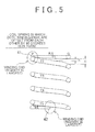
- FIG. 5 is a cross sectional view of a coil spring in which a lower effective winding end is offset from an upper effective winding end by 90 degrees (0.25 turn), in comparison with the coil spring shown in FIG. 4.
- the pressure adjusting valve 30 according to the first embodiment is denoted by reference numeral 8 in FIG. 17.
- the pressure adjusting valve 8 is disposed in the fuel tank 1 such that the pressure adjusting valve 8 is communicated with the fuel passage 5 that connects the fuel pump 2 to the injectors 6 of the engine.
- the pressure adjusting valve 8 returns excess fuel into the fuel tank 1, and appropriately adjusts the pressure of the fuel supplied to the injectors 6 to a predetermined value.
- the pressure adjusting valve 30 includes a case 32, a spring bearing portion 33, the valve element 34, and the coil spring 40.
- the case 32 is a hollow member in which a space 32a is formed. An opening is formed in the top of the case 32, and an opening is formed in the bottom of the case 32.
- a fuel inlet 31 a is formed at the end of the hollow portion of the case 32.
- a valve seat 31 b which has a truncated conical shape, is formed in the inner periphery of the lower end portion of the fuel inlet 31a. The fuel in the fuel supply system is supplied to the space 32a through the fuel inlet 31a, as shown by the arrow.
- the spring bearing portion 33 is attached to the inner peripheral surface of the lower portion of the case 32 by pressure.
- a fuel outlet 33a is formed in the center portion of the spring bearing portion 33.
- the excess fuel in the fuel supply system is returned to the fuel tank 1 through the fuel outlet 33a as shown by the arrow.
- a step portion 33b is formed in the inner bottom surface of the spring bearing portion 33 to surround the fuel outlet 33a. The step portion 33b supports the coil spring 40.
- the valve element 34 is a poppet valve, and has a conical portion 34a at the end of the valve element 34.
- the conical portion 34a faces the valve seat 31b that has a substantially truncated conical shape.
- the valve element 34 contacts the valve seat 31b. Because the surface of the conical portion 34a has a conical shape, even if the axis of the valve element 34 is slightly deviated with respect to the axis of the valve seat 31b, appropriate sealing is provided between the valve element 34 and the valve seat 31b.
- the coil spring 40 will be described.
- the coil spring 40 is a known spring formed by winding a rod-like member, which has a substantially uniform diameter, in a coil state.
- the upper end surface and the lower end surface are horizontal and parallel to each other.
- a flat surface portion is formed on each of the upper end surface and the lower end surface.
- the coil spring 40 includes a first winding portion T1, a second winding portion T2, a third winding portion T3, a fourth winding portion T4, a fifth winding portion T5, and a sixth winding portion T6 in a direction from the upper portion to the lower portion of the coil spring 40.
- the first winding portion T1 includes the upper winding end 41.
- the sixth winding portion T6 includes the lower winding end 42.
- the first winding portion T1 that is an upper-end winding portion is bent toward the second winding portion T2 so that the upper winding end 41 of the first winding portion T6 is positioned near the second winding portion T2, or the upper winding end 41 contacts the second winding portion T2.
- the upper surface of the first winding portion T1 is ground to be horizontal.
- the flat surface portion is formed on the upper surface of the first winding portion T1.
- the sixth winding portion T6 that is a lower-end winding portion is bent toward the fifth winding portion T5 so that the lower winding end 42 of the sixth winding portion T6 is positioned near the fifth winding portion T5, or the lower winding end 42 contacts the fifth winding portion T5.
- the lower surface of the sixth winding portion T6 is ground to be horizontal.
- the flat surface portion is formed on the lower surface of the sixth winding portion T6.
- FIG. 3 shows a plan view of the coil spring 40.
- a border between the horizontal surface, which is the flat surface portion, and an arc surface is denoted by reference numeral 45.
- a large area between the upper winding end 41 and the border 45, which is positioned on the right side shows the horizontal surface 43 that has been ground.
- a small area between the border 45 and the upper winding end 41, which is positioned on the left side shows the arc surface 44 that has not been ground.
- FIG. 4 is a cross sectional view taken along the line IV-IV in FIG. 3.
- the line IV-IV in FIG. 3 is equivalent to the line a-a in FIG. 2.
- the line b-b is orthogonal to the line IV-IV in FIG. 3, and the line b-b in FIG. 3 is equivalent to the line b-b in FIG. 2.
- the coil spring 40 is disposed between the step portion 34b of the valve element 34 and the step portion 33b of the spring bearing portion 33.
- the coil spring 40 makes the valve element 34 contact the valve seat 31b to prevent the fuel in the fuel passage from returning into the fuel tank 1.
- the coil spring 40 is pressed, and the valve element 34 is moved away from the valve seat 31b while the valve element 34 resists the spring force of the coil spring 40.
- the excess fuel in the fuel passage returns into the fuel tank 1.
- valve element 34 When the pressure adjusting valve 30 is opened, the valve element 34 is supported by one end of the coil spring 40 (i.e., the sixth winding portion T6 in FIG. 4, which is the lower-end winding portion) such that the valve element 34 is floated.
- the valve element 34 is moved in an extremely narrow movement range, for example, the movement range of 0 to approximately 0.3 mm.
- the upper effective winding end as referred to P of T2 and the lower effective winding end as referred to Q1 of T5 are offset from each other, for example, by 90 degrees, i.e., by 0.25 turn in the clockwise direction. As a result, it was found that the rigidities at the points differ from each other, as shown in FIG. 6B.
- the distance between the first winding portion T1 and the second winding portion T2 is approximately zero at point P, "h” at point R (or point S), and "H” at point Q.
- the distance "H” is longer than the distance "h”.
- the distance between the first winding portion T1 and the second winding portion T2 is shortest at point P of T2 at which the first winding portion T1 contacts the second winding portion T2, and the upper effective winding end is positioned.
- the distance between the fifth winding portion T5 and the sixth winding portion T6 is shortest at point Q 1 of T5 at which the fifth winding portion T5 contacts the sixth winding portion T6, and the lower effective winding end is positioned. Therefore, when the coil spring is pressed, the rigidity at point P and point R1 is larger than the rigidity at any other point. Thus, when the valve element 34 is moved upward or downward, the axis of the valve element 34 is deviated or inclined with respect to the axis of the valve seat 31b. As a result, the pressure of the fuel at a valve opening time differs from the pressure of the fuel at a valve closing time, as shown in FIG. 7 described later. Accordingly, the pressure of the fuel cannot be appropriately adjusted.
- the upper effective winding end as referred to P of T2 and the lower effective winding end as referred to Q1 of T5 are offset from each other by 180 degrees in the plan view, as shown in FIG. 4. Because the upper effective winding end as referred to P of T2 and the lower effective winding end as referred to Q1 of T5 are opposite to each other in the radial direction in the plan view, a load is substantially uniformly applied to the circumference of the coil spring 40 in the plan view. In FIG.
- the distance between the first winding portion T1 and the second winding portion T2 is substantially zero at point P of T2 at which the upper effective winding end is positioned, and the rigidity of the first winding portion T1 and the second winding portion T2 is largest at point P.
- the distance between the first winding portion T1 and the second winding portion T2 is "H" and longest at point Q that is opposite to point P, and the rigidity of the first winding portion T1 and the second winding portion T2 is smallest at point Q.
- the distance between the fifth winding portion T5 and the sixth winding portion T6 is substantially zero at point Q1 of T5 at which the lower effective winding end is positioned, and the rigidity of the fifth winding portion T5 and the sixth winding portion T6 is largest at point Q1.
- the distance between the fifth winding portion T5 and the sixth winding portion T6 is "H" and longest at point P1 that is opposite to point Q1, and the rigidity of the fifth winding portion T5 and the sixth winding portion T6 is smallest at point Q1.
- the rigidity of the coil spring 40 in the axial direction at point P is substantially the same as the rigidity of the coil spring 40 in the axial direction at point Q, although the rigidity of the upper portion (the first winding portion T1 and the second winding portion T2) is larger than the rigidity of the lower portion (the fifth winding portion T5 and the sixth winding portion T6) at point P, while the rigidity of the upper portion is smaller than the rigidity of the lower portion at point Q.
- FIG. 6A shows the result of the experiment conducted using the coil spring 40 according to the first embodiment. That is, FIG. 6A shows a change in the spring load at each of points P, R, Q, and S in accordance with the bending amount. As shown in FIG. 6A, the characteristic of the spring load at each of points P, R, Q, and S is substantially uniform.
- FIG. 7 shows experimental data showing that the difference between the pressure of the fuel at the valve opening time and the pressure of the fuel at the valve closing time (i.e. hysteresis characteristics) is reduced.
- the horizontal axis indicates the flow rate of the fuel
- the vertical axis indicates the difference between the pressure of the fuel at the valve opening time and the pressure of the fuel at the valve closing time.
- the difference between the pressure of the fuel at the valve opening time and the pressure of the fuel at the valve closing time is reduced to substantially zero, as shown by the squares in FIG. 7.
- the valve element 34 is moved upward and downward along the axis of the valve seat 31b. As a result, it is possible to reduce the difference between the pressure of the fuel at the valve opening time and the pressure of the fuel at the valve closing time, and appropriately adjust the pressure of the fuel.
- the above-described coil spring 40 is a so-called "closed-end coil spring" in which the upper winding end 41 contacts the second winding portion T2. Similarly, the lower winding end 42 contacts the fifth winding portion T5.
- the first winding portion T1 and the second winding portion T2 will be mainly described.
- the first winding portion T1 is a region that does not have a spring action, and supports the valve element 34 (i,e., a region called "a turn-end").
- the region of the coil spring 40 between the position at which the first winding portion T1 contacts the second winding portion T2, and the position at which the fifth winding portion T5 contacts the sixth winding portion T6 has a spring action.
- the position at which the first winding portion T1 contacts the second winding portion T2 is regarded as "an effective upper winding end", and the position at which the fifth winding portion T5 contacts the sixth winding portion T6 is regarded as "an effective lower winding end”.
- the region between the effective upper winding end and the effective lower winding end is regarded as "an effective winding region”.
- the upper winding end 41 is positioned above the effective upper winding end, In the plan view, the effective upper winding end and the upper winding end 41 are at the same position.
- FIGS. 15A to 15C show changes in the effective winding region between the first winding portion T1 and the second winding portion T2.
- FIG. 15A shows the state of the coil spring 40 when the coil spring 40 is set and the bending amount is zero.
- FIG. 15B shows the state of the coil spring 40 when the bending amount is small.
- FIG. 15C shows the state of the coil spring 40 when the bending amount is large.
- the contact portion where the upper winding end 41 contacts the second winding portion T2 i.e., the effective upper winding end is at the leftmost position, and the entire region on the right side of the contact portion is the effective winding region.
- the effective winding region extends to the contact portion where the fifth winding portion T5 contacts the sixth winding portion T6.
- the above-described problem is caused because the contact portions, i.e., the positions of the effective upper and lower winding ends are moved, and the effective winding region is reduced.
- attention is focused on the effective upper and lower winding ends. That is, the effective upper and lower winding ends are offset from each other by 180 degrees in the plan view.
- the effective upper and lower winding ends are prevented from moving, to prevent the decrease in the effective winding region of the coil spring 40 when the valve element 34 is operated.
- the invention may be applied not only to the closed-end coil spring, but also to a so-called open-end constant-pitch spring that is an open-end spring with a constant pitch.
- FIG. 8 shows a coil spring 40a that is a closed-end coil spring, as well as the coil spring 40 shown in FIG. 2.
- wedge-shaped spacers 49 are fixed by brazing, welding, or the like between the first winding portion T1, which is the turn-end, and the second winding portion T2, and between the sixth winding portion T6, which is the turn-end, and the fifth winding portion T5.
- Each spacer 49 has the largest thickness S 1.
- the position at which the upper spacer 49 has the largest thickness S1 is offset from the position at which the lower spacer 49 has the largest thickness S by 180 degrees in the plan view.
- the position at which the upper spacer 49 has the largest thickness S1 is the position of the effective upper winding end
- the position at which the lower spacer 49 has the largest thickness S1 is the position of the effective lower winding end.
- FIG. 15D shows the state of the coil spring 40a.
- the gap S1 which is equal to the largest thickness of the spacer 49, is formed.
- the positions of the gaps S 1 are regarded as the positions of the contact portions. That is, the positions of the gaps S 1 are the positions of the effective upper and lower winding ends.
- the adjacent winding portions between the effective upper and lower winding ends do not contact each other, and therefore, the effective winding region is not changed when the valve element 34 is operated. This makes it possible to obtain the desired effect of accurately adjusting the pressure of the fuel.
- FIG. 9 shows a third embodiment in which the so-called open-end constant-pitch spring is used.
- a coil spring unit 54 is used.
- the coil spring unit 54 includes one coil spring 50 and two support members 55.
- the coil spring unit 54 may be regarded as "the coil spring".
- FIG. 9 shows only the upper end portion of the coil spring unit 54, the lower end portion of the coil spring unit 54 is similar to the upper end portion.
- the coil spring 50 is the so-called open-end constant-pitch spring.
- FIG. 10A is a front view of the support member 55.
- FIG. 10B is a rear view of the support member 55.
- the support member 55 is made of metal or resin.
- the support member 55 includes a flange portion 56 at the upper end, and a column portion 57 at the lower end.
- a horizontal flat surface portion 56a is formed on the upper surface of the flange portion 56.
- a spiral surface 59 is formed on the lower surface of the flange portion 56, as shown in FIGS. 9 and 10A and 10B.
- the spiral surface 59 has a predetermined length (substantially the same length as that of the first winding portion T1 in FIG. 9), and extends downward from an upper start portion 58.
- the column portion 57 is a cylindrical member including a hollow portion 57a.
- the hollow portion 57a extends from the top of the column portion 57 to the bottom of the column portion 57.
- the outer periphery of the column portion 57 is fitted in the inner periphery of the coil spring 50.
- the first winding portion T1 is fitted to the column portion 57 such that the upper winding end 50a of the coil spring 50 contacts the start portion 58.
- each of the first winding portion T1 and the lower-end winding portion is used as a supported portion that is supported by the support member 55.
- the valve element 34 is fitted in the hollow portion 57a that extends from the top to the bottom of the column portion 57.
- the valve element 34 may be integrally formed on the upper surface of the support member 55. With this configuration, it is possible to reduce the number of components, and the number of man-hours required in an assembly process.
- the position of each of the upper and lower effective winding ends is the position of the border between the region of the coil spring 50 that closely contacts the spiral surface 59 and the region of the coil spring 50 that does not closely contact the spiral surface 59, that is, the position shown by the arrow P in FIG. 9. That is, in this embodiment, the positions of the effective upper and lower winding ends P are offset from each other by 180 degrees in the plan view. As a result, a gap S2 is formed at the position of the effective upper end P as shown in FIG. 9, and at the position, which is offset from the effective upper end P by 180 degrees in the plan view, of the effective lower end, a gap is also formed.
- the upper winding end 50a and the lower winding end may be, or may not be offset from each other by 180 degrees in the plan view.
- FIG. 11 shows a fourth embodiment in which the so-called open-end constant-pitch spring is used, as in the third embodiment shown in FIG. 9.
- a coil spring unit 60 is used.
- the coil spring unit 60 includes one coil spring 50 and two support members 61.
- the coil spring unit 60 may be regarded as "the coil spring".
- FIG. 11 shows only the upper end portion of the coil spring unit 60, the lower end portion of the coil spring unit 60 is similar to the upper end portion.
- FIG. 12A is a front view of the support member 61.
- FIG. 12B is a rear view of the support member 61.
- the support member 61 is made of metal or resin.
- the support member 61 having a columnar shape includes a hollow portion 61b that extends from the top to the bottom of the support member 61.
- a horizontal flat surface portion 61a is formed on the upper surface of the support member 61.
- a spiral surface 62 is formed along the outer periphery of the support member 61.
- the spiral surface 62 has a predetermined length (substantially the same length as that of the first winding portion T1 in FIG. 11), and extends downward from an upper start portion 63.
- a protrusion 64 is formed to extend along a circumferential direction, and in parallel with the spiral surface 62. There is a gap S3 between the upper surface of the second winding portion T2 and a portion of the lower surface of the protrusion 64, which is at the same position as the start portion 63 in the plan view.
- the first winding portion T1 is fitted to the spiral surface 62 such that the upper winding end 50a of the coil spring 50 contacts the start portion 63.
- Each of the first winding portion T1 and the lower-end winding portion is used as a supported portion that is supported by the support portion 61.
- valve element 34 When the coil spring unit 60 is used, the valve element 34 is fitted in the hollow portion 61b that extends from the top to the bottom of the support member 61.
- the valve element 34 may be integrally formed on the upper surface of the support member 61. With this configuration, it is possible to reduce the number of components, and the number of man-hours required in an assembly process.
- the position of each of the upper and lower effective winding ends is the position of the border between the region of the coil spring 50 that closely contacts the spiral surface 62 and the region of the coil spring 50 that does not closely contact the spiral surface 62, that is, the position shown by the arrow Q in FIG. 11. That is, in this embodiment, the positions of the effective upper and lower winding ends Q are offset from each other by 180 degrees in the plan view. As a result, a gap S3 is formed at the position of the effective upper end Q as shown in FIG. 11, and at the position, which is offset from the effective upper winding end Q by 180 degrees in the plan view, of the lower winding end, a gap is formed.
- the upper winding end 50a and the lower winding end may be, or may not be offset from each other by 180 degrees in the plan view.
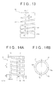
- FIG. 13 shows a fifth embodiment in which a coil spring 80 is formed using a spring steel pipe.
- the coil spring 80 is formed by forming a spiral opening 81 on the spring steel pipe that has a cylindrical shape.
- the spiral opening 81 has a constant pitch.
- the coil spring 80 includes the first winding portion T1 that is the turn-end, the second winding portion T2, the third winding portion T3, the fourth winding portion T4, the fifth winding portion T5, and the sixth winding portion T6 that is the turn-end, in the direction from the upper portion to the lower portion of the coil spring 80.
- the valve element 34 is fitted in an opening that extends from the top to the bottom of the coil spring 80.
- the valve element 34 may be integrally formed on the upper surface of the coil spring 80.
- the coil spring 80 is the open-end constant-pitch spring.
- the positions of the effective upper and lower winding ends are the positions of the upper end 81a and the lower end 81b of the spiral opening 81 shown in FIG. 13.
- the positions of the upper end 81a and the lower end 81b are offset from each other by 180 degrees in the plan view.
- a gap S4 is formed at the position of the upper end 81a, as shown in FIG. 13, and at the position of the lower end 81b.
- FIGS. 14A and 14B show a sixth embodiment in which a coil spring 70 is used.
- the coil spring 70 is the so-called open-end constant-pitch spring.
- a horizontal flat surface portion 71 is formed on the upper surface of the first winding portion T1 that is the turn-end.
- the horizontal flat surface portion 71 is also formed on the lower surface of the sixth winding portion T6 that is the turn-end.
- the coil spring 70 has a rectangular cross section.
- the coil spring 70 satisfies the equations, b > a, and b ⁇ (5 / 8) p, wherein “b” represents the length of the coil spring 70 in the axial direction, “a” represents the length of the coil spring 70 in the radial direction, and “p” represents the pitch.
- the flat surface portion 71 is formed in the range of at least 225 degrees on the upper surface of the first winding portion T1.
- the flat surface portion 71 may be formed in any range, as long as the axis of the valve element 34 is not inclined when the valve element 34 is operated.
- the flat surface portion 71 may be formed in the range of at least 180 degrees.
- the range in which the flat surface portion is formed may be applied to each of the above-described embodiments.
- the effective upper winding end is an inclination start portion 72a that is the border between the horizontal flat surface portion 71 of the first winding portion T1, on which the valve element 34 is placed, and an inclination portion 72 that is continuous with the flat surface portion 71.
- the effective lower winding end is an inclination start portion 72b that is the border between the horizontal flat surface portion 71 of the sixth winding portion T6, which contacts the spring bearing portion 33, and the inclination portion 72 that is continuous with the flat surface portion 71.
- the coil spring 70 is formed such that the inclination start portions 72a and 72b are offset from each other by 180 degrees.
- the flat surface portion 71 and the inclination portion 72 are continuous with each other. That is, means for forming a space is not used in this embodiment, unlike the embodiments shown in FIGS. 8, 9, 11, and 13. Therefore, there may be concern that the inclination start portions 72a and 72b may be moved when the valve element 34 is operated, as described with reference to FIGS. 15A to 15C.
- the coil spring 70 used in the embodiment is the so-called open-end constant-pitch spring, a wide angle ⁇ is maintained between the first winding portion T1 and the second winding portion T2, as shown in FIG. 15E, even when the valve element 34 is operated.
- the coil spring 70 has a rectangular cross section.
- the coil spring 70 may have, for example, an oval cross section,
- the invention is not limited to the configurations in the above-described embodiments.
- the design may be appropriately changed in the scope of the invention.
- the valve element that has a sphere shape, a flat shape, or an arc shape may be used.
- the pressure adjusting valve may be used not only for a vehicle, but also for the other applications.
Landscapes
- Engineering & Computer Science (AREA)
- General Engineering & Computer Science (AREA)
- Mechanical Engineering (AREA)
- Chemical & Material Sciences (AREA)
- Combustion & Propulsion (AREA)
- Springs (AREA)
- Fuel-Injection Apparatus (AREA)
- Safety Valves (AREA)
- Check Valves (AREA)
- Compressor (AREA)
Abstract
Description
- The invention relates to a coil spring of a valve, in particular, a coil spring of a valve that is provided in a passage through which fluid is delivered from a tank by a pump, and that adjusts the pressure of the fluid, for example, a valve that adjusts the pressure of fuel supplied from a fuel tank to the injector of an internal combustion engine by a fuel pump.
- A fuel supply system of a vehicle or the like, which is a system for supplying fluid, includes a
fuel passage 5 that connects afuel tank 1, afuel pump 2, and theinjectors 6 of an engine, as shown in FIG. 17. The fuel in thefuel tank 1 is supplied to theinjectors 6 of the engine viafilters 3 and 4 by thefuel pump 2 provided in thefuel tank 1. In this case, the pressure of the fuel in thefuel passage 5 fluctuates according to, for example, the operating state of the engine. Therefore, apressure adjusting valve 8, which adjusts the pressure of the fuel to a predetermined value, is provided in the fuel supply system. Thepressure adjusting valve 8 is provided in abranch passage 7 that extends from thefuel passage 5. When the pressure in the fuel supply system is equal to or above the predetermined value, thepressure adjusting valve 8 is opened to return the fuel to thefuel tank 1. - FIG. 16 shows an example of a conventional
pressure adjusting valve 10. Thepressure adjusting valve 10 includes acase 11, avalve element 14, and acoil spring 16. Thecase 11 is a member that forms the framework of thepressure adjusting valve 10. Thecase 11 includes afuel inlet 12, and afuel outlet 13. Avalve seat 18 is formed near thefuel inlet 12 on the inner surface of thecase 11. Aspring bearing portion 17 is formed in the bottom portion of thecase 11. - The
valve element 14 includes acylindrical portion 15. Thevalve element 14 is moved upward and downward in thecase 11 while thecylindrical portion 15 is moved along the inner surface of thecase 11. Thecoil spring 16 is provided between the inner bottom surface of thevalve element 14 and thespring bearing portion 17. Thecoil spring 16 constantly presses thevalve element 14 toward thefuel inlet 12 so that the end of thevalve element 14 contacts thevalve seat 18, and communication between the fuel supply system and thefuel tank 1 is interrupted. However, when the pressure of the fuel in the fuel supply system is equal to or above the predetermined value, thecoil spring 16 is pressed downward by thevalve element 14. As a result, thevalve element 14 is moved away from thevalve seat 18, and accordingly, excess fuel is returned into thefuel tank 1. In thepressure adjusting valve 10, thecylindrical portion 15, which is moved along the inner surface of thecase 11, is provided. Therefore, the axis of thevalve element 14 is not deviated from the axis of thevalve seat 18, and appropriate sealing is provided between thevalve element 14 and thevalve seat 18. On the other hand, the axis of thevalve element 14 is slightly inclined due to fit dimension tolerance and shape tolerance. Accordingly, thevalve element 14 is not moved smoothly. As a result, the pressure of the fuel at a valve opening time differs from the pressure of the fuel at a valve closing time. Also, the fit portion, which is moved along the inner surface of the case, needs to be formed with high dimension accuracy. This increases the cost (refer toJapanese Patent Application Publication No. 8-320074 JP-A-8-320074 - To solve such a problem, for example, a poppet valve, which includes a conic valve element as shown in FIG. I, is available. In the poppet valve, the
valve element 34 does not include a member that is moved along the inner surface of a case, and thevalve element 34 is supported by acoil spring 40. When thevalve element 34 opens a fuel inlet, thevalve element 34 is supported by one end of thecoil spring 40 such that thevalve element 34 is floated. Also, when thevalve element 34 closes the fuel inlet, thecoil spring 40 makes thevalve element 34 contact avalve seat 31b, - In such a poppet valve, the valve element has a conical shape. Even if the axis of the valve element is slightly deviated or inclined with respect to the axis of the seat valve when the valve element contacts the valve seat to close the fuel inlet, appropriate sealing is provided. Thus, although measures are taken, for example, so that the quality of the material of the coil spring is uniform, and the entire coil spring has a uniform diameter, no particular consideration has been given to a measure to be taken so that a load is uniformly applied to the entire circumference of the coil spring when the coil spring extends or contracts. For example, no particular consideration has been given to how the upper and lower effective winding ends in the upper side and lower side of the coil spring should be arranged in the plan view. Accordingly, when the conventional coil spring extends or contracts, the axis of the coil spring tends to be deviated or inclined with respect to the axis of the valve seat.
- In recent years, it has become necessary to more accurately control the supply of fuel in a vehicle or the like. Accordingly, it has become necessary to more accurately adjust the pressure of the fuel using the pressure adjusting valve. However, as described above, the axis of the conventional coil spring tends to be deviated or inclined with respect to the axis of the valve seat when the conventional coil spring extends or contracts. If the axis of the coil spring is deviated or inclined with respect to the axis of the valve seat when the coil spring extends or contracts, the axis of the valve element is also deviated or inclined with respect to the axis of the valve seat when the valve element opens or closes the fuel inlet. If the axis of the valve element is deviated or inclined, for example, the pressure of the fuel when the valve element opens the fuel inlet differs from the pressure of the fuel when the valve element closes the fuel inlet, or appropriate sealing is not provided between the valve element and the valve seat. As a result, it is not possible to sufficiently satisfy the need of accurately adjusting the pressure of the fuel.
- It is an object of the invention to provide a valve in which the characteristic of a load is uniform on the entire circumference of a coil spring in a plan view.
- To achieve the above-described object, the following configurations are employed according to the invention.
- According to a first aspect of the invention, a valve includes a valve element, a valve seat, a coil spring, and a spring bearing portion, The coil spring, provided between the valve element and the spring bearing portion, presses the valve element toward the valve seat. An effective upper winding end of the coil spring and an effective lower winding end of the coil spring are offset from each other by 180 degrees in a plan view.
- According to a second aspect of the invention, in the valve according to the first aspect, when the valve element is moved in a movement range, adjacent winding portions of the coil spring may be provided not to contact each other.
- According to a third aspect of the invention, in the valve according to the second or third aspect, the coil spring includes a first winding portion that contacts the valve element, a second winding portion that is continuous with the first winding portion, a third winding portion that contacts the spring bearing portion, and a fourth winding portion that is continuous with the third winding portion. When the valve element is moved in the movement range, positions of the effective upper winding end and the effective lower winding end may be maintained by disposing the first winding portion and the second winding portion such that the first winding portion and the second winding portion do not contact each other, and the third winding portion, and by disposing the fourth winding portion such that the third winding portion and the fourth winding portion do not contact each other.
- According to a fourth aspect of the invention, in the valve according to the first or second aspect, the coil spring includes a first winding portion that contacts the valve element, a second winding portion that is continuous with the first winding portion, a third winding portion that contacts the spring bearing portion, and a fourth winding portion that is continuous with the third winding portion. The first winding portion and the second winding portion may be disposed such that a clearance between the first winding portion and the second winding portion is maintained when the valve element is moved in a movement range, and the third winding portion and the fourth winding portion may be disposed such that a clearance between the third winding portion and the fourth winding portion is maintained when the valve element is moved in the movement range.
- According to a fifth aspect of the invention, in the valve according to the third or fourth aspect, the valve may has a first spacer disposed between the first winding portion and the second winding portion, and/or a second spacer disposed between the third winding portion and the fourth winding portion.
- According to a sixth aspect of the invention, in the valve according to any one of the first to fourth aspects, the coil spring may include an open-end constant-pitch spring, an upper support member that is attached to an upper-end winding portion of the open-end constant-pitch spring, and a lower support member that is attached to a lower-end winding portion of the open-end constant-pitch spring. The upper support member and the lower support member are opposite to each other through the open-end constant-pitch spring, and an upper spiral surface is formed on a surface of the upper support member, and a lower spiral surface is formed on a surface of the lower support member, the surface of the upper support member and the surface of the lower support member being opposite to each other. There is a distance equivalent to a pitch of the open-end constant-pitch spring between a start portion of the upper spiral surface and a portion of the upper spiral surface, which is at a same position as the start portion of the upper spiral surface in the plan view. There is the distance equivalent to the pitch of the open-end constant-pitch spring between a start portion of the lower spiral surface and a portion of the lower spiral surface, which is at a same position as the start portion of the lower spiral surface in the plan view. The upper spiral surface receives the upper-end winding portion of the open-end constant-pitch spring, and the lower spiral surface receives the lower-end winding portion of the open-end constant-pitch spring.
- According to a seventh aspect of the invention, in the valve according to the sixth aspect, an upper protrusion may be formed in the upper support member such that the upper protrusion extends in parallel with the upper spiral surface, and there is a distance shorter than the pitch between the upper protrusion and the upper spiral surface; and a lower protrusion may be formed in the lower support member such that the lower protrusion extends in parallel with the lower spiral surface, and there is the distance shorter than the pitch between the lower protrusion and the lower spiral surface.
- According to an eighth aspect of the invention, in the valve according to any one of the first to the sixth aspects, the coil spring may be an open-end constant-pitch spring that has a rectangular cross section that has a long side extending in an axial direction of the coil spring, and a short side extending in a radial direction of the coil spring, and a flat surface portion may be formed in each of the upper-end winding portion and the lower-end winding portion.
- According to a ninth aspect of the invention, in the valve according to any one of the first to the sixth aspects, the coil spring may be formed by forming a spiral opening that has a constant pitch on an outer periphery of a spring steel pipe.
- According to a tenth aspect of the invention, in the valve according to any one of the first to the tenth aspects, the valve may be disposed in a passage through which fluid is delivered from a tank by a pump. When a pressure of the fluid in the passage is equal to or lower than a predetermined value, the valve element contacts the valve seat to close the passage, and when the pressure of the fluid is higher than the predetermined value, the valve element is moved away from the valve seat to open the passage.
- According to an eleventh aspect of the invention, in the valve according to any one of the first to the tenth aspects, the valve is used in a fuel system of a vehicle.
- With this configuration, the characteristic of a load is made substantially uniform on the circumference of the valve in the plan view. Thus, the valve element of the valve is maintained in a perpendicular position. Therefore, when the valve element is moved in the movement range to adjust the pressure of the fluid, the axis of the valve element remains substantially the same as the axis of the inlet for the fluid.
- According to the aspects of the invention, an effective upper winding end and an effective lower winding end are offset from each other by 180 degrees in a plan view. Therefore, the load applied from the valve element is made substantially uniform on the entire circumference of the coil spring in the plan view. Thus, the valve element of the valve is maintained in the perpendicular position. Therefore, when the valve element is moved in the movement range, the axis of the valve element remains substantially the same as the axis of the inlet for the fluid. Also, it is possible to reduce the difference between the pressure of the fuel at a valve opening time and the pressure of the fuel at a valve closing time, and to improve the sealing performance at the valve closing time. Further, a member which is moved along the inner surface of the case of the valve does not need to be formed in the valve element with high dimension accuracy. This decreases the production cost.
- The foregoing and further objects, features and advantages of the invention will become apparent from the following description of preferred embodiments with reference to the accompanying drawings, wherein like numerals are used to represent like elements and wherein:
- FIG. 1 is a cross sectional view of a pressure adjusting valve according to the invention;
- FIG. 2 is a perspective view of a coil spring according to the invention, in which upper and lower effective winding ends are offset from each other by 180 degrees (0.5 turn), when the coil spring is set;
- FIG. 3 is a plan view of the coil spring according to the invention, in which upper and lower effective winding ends are offset from each other by 180 degrees, when the coil spring is set;
- FIG. 4 is a cross sectional view taken along the line IV-IV in FIG. 3;
- FIG. 5 is a cross sectional view of a coil spring in which upper and lower effective winding ends are offset from each other by 90 degrees (0.25 turn), when the coil spring is set;
- FIG. 6A is a diagram showing the characteristic of the coil spring according to the invention, and FIG. 6B is a diagram showing the characteristic of the coil spring shown in FIG. 5;
- FIG. 7 is a comparative diagram showing differences in the pressure of fuel when the coil spring according to the invention is used, and when the coil spring shown in FIG. 5 is used;
- FIG. 8 is a partial cross sectional view of a coil spring according to the invention, in which effective upper and lower winding ends are offset from each other by 180 degrees;
- FIG 9 is a partial cross sectional view of another coil spring according to the invention, in which effective upper and lower winding ends are offset from each other by 180 degrees;
- FIG. 10A is a front view of a support member shown in FIG. 9, and FIG. 10B is a rear view of the support member shown in FIG. 9;
- FIG. 11 is a partial cross sectional view of another coil spring according to the invention, in which effective upper and lower winding ends are offset from each other by 180 degrees;
- FIG. 12A is a front view of a support member shown in FIG. 11, and FIG. 12B is a rear view of the support member shown in FIG. 11;
- FIG. 13 is a front view of another coil spring according to the invention, in which effective upper and lower spring ends are offset from each other by 180 degrees;
- FIG. 14A and FIG. 14B are a cross sectional view and a front view of another coil spring according to the invention, in which effective upper and lower spring ends are offset from each other by 180 degrees;
- FIGS. 15A to 15E are diagrams showing changes in an effective winding region between a first winding portion T1 and a second winding portion T2 in accordance with a bending amount, according to the invention;
- FIG. 16 is a cross sectional view of a conventional pressure adjusting valve; and
- FIG. 17 is a schematic diagram showing a fuel supply system of a vehicle.
- FIG. 1 shows a pressure adjusting valve that includes a coil spring according to a first embodiment of the invention. FIG. 2 is a cross sectional view of the coil spring according to the first embodiment, in which an upper effective winding end and a lower effective winding end are offset from each other by 180 degrees (i.e., by 0.5 turn), according to the first embodiment. FIG. 3 is a plan view of the coil spring. FIG. 4 is a cross sectional view taken along the line IV-IV in FIG. 3. FIG. 5 is a cross sectional view of a coil spring in which a lower effective winding end is offset from an upper effective winding end by 90 degrees (0.25 turn), in comparison with the coil spring shown in FIG. 4.
- The
pressure adjusting valve 30 according to the first embodiment is denoted byreference numeral 8 in FIG. 17. Thepressure adjusting valve 8 is disposed in thefuel tank 1 such that thepressure adjusting valve 8 is communicated with thefuel passage 5 that connects thefuel pump 2 to theinjectors 6 of the engine. For example, thepressure adjusting valve 8 returns excess fuel into thefuel tank 1, and appropriately adjusts the pressure of the fuel supplied to theinjectors 6 to a predetermined value. - The
pressure adjusting valve 30 includes acase 32, aspring bearing portion 33, thevalve element 34, and thecoil spring 40. Thecase 32 is a hollow member in which aspace 32a is formed. An opening is formed in the top of thecase 32, and an opening is formed in the bottom of thecase 32. Afuel inlet 31 a is formed at the end of the hollow portion of thecase 32. Avalve seat 31 b, which has a truncated conical shape, is formed in the inner periphery of the lower end portion of thefuel inlet 31a. The fuel in the fuel supply system is supplied to thespace 32a through thefuel inlet 31a, as shown by the arrow. - The
spring bearing portion 33 is attached to the inner peripheral surface of the lower portion of thecase 32 by pressure. Afuel outlet 33a is formed in the center portion of thespring bearing portion 33. The excess fuel in the fuel supply system is returned to thefuel tank 1 through thefuel outlet 33a as shown by the arrow. Astep portion 33b is formed in the inner bottom surface of thespring bearing portion 33 to surround thefuel outlet 33a. Thestep portion 33b supports thecoil spring 40. - The
valve element 34 is a poppet valve, and has aconical portion 34a at the end of thevalve element 34. Theconical portion 34a faces thevalve seat 31b that has a substantially truncated conical shape. When thepressure adjusting valve 30 is closed, thevalve element 34 contacts thevalve seat 31b. Because the surface of theconical portion 34a has a conical shape, even if the axis of thevalve element 34 is slightly deviated with respect to the axis of thevalve seat 31b, appropriate sealing is provided between thevalve element 34 and thevalve seat 31b. - The
coil spring 40 will be described. Thecoil spring 40 is a known spring formed by winding a rod-like member, which has a substantially uniform diameter, in a coil state. The upper end surface and the lower end surface are horizontal and parallel to each other. Thus, a flat surface portion is formed on each of the upper end surface and the lower end surface. More specifically, as shown in FIG. 4, thecoil spring 40 includes a first winding portion T1, a second winding portion T2, a third winding portion T3, a fourth winding portion T4, a fifth winding portion T5, and a sixth winding portion T6 in a direction from the upper portion to the lower portion of thecoil spring 40. The first winding portion T1 includes the upper windingend 41. The sixth winding portion T6 includes the lower windingend 42. In thecoil spring 40, the first winding portion T1 that is an upper-end winding portion is bent toward the second winding portion T2 so that the upper windingend 41 of the first winding portion T6 is positioned near the second winding portion T2, or the upper windingend 41 contacts the second winding portion T2. In addition, the upper surface of the first winding portion T1 is ground to be horizontal. Thus, the flat surface portion is formed on the upper surface of the first winding portion T1. Similarly, the sixth winding portion T6 that is a lower-end winding portion is bent toward the fifth winding portion T5 so that the lower windingend 42 of the sixth winding portion T6 is positioned near the fifth winding portion T5, or the lower windingend 42 contacts the fifth winding portion T5. In addition, the lower surface of the sixth winding portion T6 is ground to be horizontal. Thus, the flat surface portion is formed on the lower surface of the sixth winding portion T6. - FIG. 3 shows a plan view of the
coil spring 40. In FIG. 3, a border between the horizontal surface, which is the flat surface portion, and an arc surface is denoted byreference numeral 45. In FIG. 3, a large area between the upper windingend 41 and theborder 45, which is positioned on the right side, shows thehorizontal surface 43 that has been ground. A small area between theborder 45 and the upper windingend 41, which is positioned on the left side, shows thearc surface 44 that has not been ground. FIG. 4 is a cross sectional view taken along the line IV-IV in FIG. 3. The line IV-IV in FIG. 3 is equivalent to the line a-a in FIG. 2. The line b-b is orthogonal to the line IV-IV in FIG. 3, and the line b-b in FIG. 3 is equivalent to the line b-b in FIG. 2. - The
coil spring 40 is disposed between thestep portion 34b of thevalve element 34 and thestep portion 33b of thespring bearing portion 33. When the pressure of the fuel in the fuel passage is equal to or lower than the predetermined value, thecoil spring 40 makes thevalve element 34 contact thevalve seat 31b to prevent the fuel in the fuel passage from returning into thefuel tank 1. When the pressure of the fuel in the fuel passage is higher than the predetermined value, thecoil spring 40 is pressed, and thevalve element 34 is moved away from thevalve seat 31b while thevalve element 34 resists the spring force of thecoil spring 40. Thus, the excess fuel in the fuel passage returns into thefuel tank 1. When thepressure adjusting valve 30 is opened, thevalve element 34 is supported by one end of the coil spring 40 (i.e., the sixth winding portion T6 in FIG. 4, which is the lower-end winding portion) such that thevalve element 34 is floated. Thevalve element 34 is moved in an extremely narrow movement range, for example, the movement range of 0 to approximately 0.3 mm. - No particular consideration has been given to the positional relation between the upper effective winding end as referred to P of T2, and the lower effective winding end as referred to Q1 of T5. An experiment was conducted on rigidities at point P (i.e., 0-degree position with respect to the winding end), point R (i.e., 90-degree position with respect to the winding end), point Q (i.e., 180-degree position with respect to the winding end), and point S (i.e., 270-degree position with respect to the winding end) in FIG. 3, with respect to the bending amount of the coil spring, In this experiment, the coil spring shown in FIG. 5 was used. In the coil spring shown in FIG. 5, the upper effective winding end as referred to P of T2 and the lower effective winding end as referred to Q1 of T5 are offset from each other, for example, by 90 degrees, i.e., by 0.25 turn in the clockwise direction. As a result, it was found that the rigidities at the points differ from each other, as shown in FIG. 6B.
- The reasons why the rigidities at the points differ from each other are considered to be as follows. In FIG. 5, the distance between the first winding portion T1 and the second winding portion T2 is approximately zero at point P, "h" at point R (or point S), and "H" at point Q. The distance "H" is longer than the distance "h". Thus, the distance between the first winding portion T1 and the second winding portion T2 is shortest at point P of T2 at which the first winding portion T1 contacts the second winding portion T2, and the upper effective winding end is positioned. The distance between the fifth winding portion T5 and the sixth winding portion T6 is shortest at
point Q 1 of T5 at which the fifth winding portion T5 contacts the sixth winding portion T6, and the lower effective winding end is positioned. Therefore, when the coil spring is pressed, the rigidity at point P and point R1 is larger than the rigidity at any other point. Thus, when thevalve element 34 is moved upward or downward, the axis of thevalve element 34 is deviated or inclined with respect to the axis of thevalve seat 31b. As a result, the pressure of the fuel at a valve opening time differs from the pressure of the fuel at a valve closing time, as shown in FIG. 7 described later. Accordingly, the pressure of the fuel cannot be appropriately adjusted. - In the
coil spring 40 according to one embodiment of the invention, the upper effective winding end as referred to P of T2 and the lower effective winding end as referred to Q1 of T5 are offset from each other by 180 degrees in the plan view, as shown in FIG. 4. Because the upper effective winding end as referred to P of T2 and the lower effective winding end as referred to Q1 of T5 are opposite to each other in the radial direction in the plan view, a load is substantially uniformly applied to the circumference of thecoil spring 40 in the plan view. In FIG. 4, the distance between the first winding portion T1 and the second winding portion T2 is substantially zero at point P of T2 at which the upper effective winding end is positioned, and the rigidity of the first winding portion T1 and the second winding portion T2 is largest at point P. The distance between the first winding portion T1 and the second winding portion T2 is "H" and longest at point Q that is opposite to point P, and the rigidity of the first winding portion T1 and the second winding portion T2 is smallest at point Q. The distance between the fifth winding portion T5 and the sixth winding portion T6 is substantially zero at point Q1 of T5 at which the lower effective winding end is positioned, and the rigidity of the fifth winding portion T5 and the sixth winding portion T6 is largest at point Q1. The distance between the fifth winding portion T5 and the sixth winding portion T6 is "H" and longest at point P1 that is opposite to point Q1, and the rigidity of the fifth winding portion T5 and the sixth winding portion T6 is smallest at point Q1. - Thus, because the upper effective winding end as referred to P of T2 and the lower effective winding end as referred to
Q 1 of T5 are offset from each other by 180 degrees in the plan view, the rigidity of thecoil spring 40 in the axial direction at point P is substantially the same as the rigidity of thecoil spring 40 in the axial direction at point Q, although the rigidity of the upper portion (the first winding portion T1 and the second winding portion T2) is larger than the rigidity of the lower portion (the fifth winding portion T5 and the sixth winding portion T6) at point P, while the rigidity of the upper portion is smaller than the rigidity of the lower portion at point Q. Further, the distance between the first winding portion T1 and the second winding portion T2 at point R is substantially the same as the distance between the first winding portion T1 and the second winding portion T2 at point S. The distance between the fifth winding portion T5 and the sixth winding portion T6 at point R1 is substantially the same as the distance between the fifth winding portion T5 and the sixth winding portion T6 at point S1. Therefore, the rigidity of thecoil spring 40 in the axial direction at point R is substantially the same as the rigidity of thecoil spring 40 in the axial direction at point S. FIG. 6A shows the result of the experiment conducted using thecoil spring 40 according to the first embodiment. That is, FIG. 6A shows a change in the spring load at each of points P, R, Q, and S in accordance with the bending amount. As shown in FIG. 6A, the characteristic of the spring load at each of points P, R, Q, and S is substantially uniform. - FIG. 7 shows experimental data showing that the difference between the pressure of the fuel at the valve opening time and the pressure of the fuel at the valve closing time (i.e. hysteresis characteristics) is reduced. In FIG. 7, the horizontal axis indicates the flow rate of the fuel, and the vertical axis indicates the difference between the pressure of the fuel at the valve opening time and the pressure of the fuel at the valve closing time. When using the coil spring in which the upper effective winding end and the lower effective winding end are offset from each other by 90 degrees, the pressure of the fuel at the valve opening time greatly differs from the pressure of the fuel at the valve closing time, as shown by the circles in FIG. 7. In contrast, when using the
coil spring 40 according to the first embodiment, in which the upper effective winding end and the lower effective winding end are offset from each other by 180 degrees, the difference between the pressure of the fuel at the valve opening time and the pressure of the fuel at the valve closing time is reduced to substantially zero, as shown by the squares in FIG. 7. By using thecoil spring 40 according to the first embodiment, thevalve element 34 is moved upward and downward along the axis of thevalve seat 31b. As a result, it is possible to reduce the difference between the pressure of the fuel at the valve opening time and the pressure of the fuel at the valve closing time, and appropriately adjust the pressure of the fuel. - The above-described
coil spring 40 is a so-called "closed-end coil spring" in which the upper windingend 41 contacts the second winding portion T2. Similarly, the lower windingend 42 contacts the fifth winding portion T5. Hereinafter, however, the first winding portion T1 and the second winding portion T2 will be mainly described. In such a closed-end coil spring, the first winding portion T1 is a region that does not have a spring action, and supports the valve element 34 (i,e., a region called "a turn-end"). The region of thecoil spring 40 between the position at which the first winding portion T1 contacts the second winding portion T2, and the position at which the fifth winding portion T5 contacts the sixth winding portion T6 has a spring action. The position at which the first winding portion T1 contacts the second winding portion T2 is regarded as "an effective upper winding end", and the position at which the fifth winding portion T5 contacts the sixth winding portion T6 is regarded as "an effective lower winding end". Thus, the region between the effective upper winding end and the effective lower winding end is regarded as "an effective winding region". The upper windingend 41 is positioned above the effective upper winding end, In the plan view, the effective upper winding end and the upper windingend 41 are at the same position. - The action of the closed-end coil spring will be described with reference to FIGS. 15A to 15C. After the
valve element 34 is set, the lower surface of the upper windingend 41 contacts the upper surface of the second winding portion T2. Similarly, the upper surface of the lower windingend 42 contacts the lower surface of the fifth winding portion T5. However, hereinafter, the first winding portion T1 and the second winding portion T2 will be mainly described. When thevalve element 34 is operated, thecoil spring 40 is pressed downward, and the pitch is decreased. The clearance between the first winding portion T1 and the second winding portion T2 changes as shown in FIGS. 15A to 15C. - FIGS. 15A to 15C show changes in the effective winding region between the first winding portion T1 and the second winding portion T2. FIG. 15A shows the state of the
coil spring 40 when thecoil spring 40 is set and the bending amount is zero. FIG. 15B shows the state of thecoil spring 40 when the bending amount is small. FIG. 15C shows the state of thecoil spring 40 when the bending amount is large, In FIG 15A in which the bending amount is zero, the contact portion where the upper windingend 41 contacts the second winding portion T2, i.e., the effective upper winding end is at the leftmost position, and the entire region on the right side of the contact portion is the effective winding region. In this case, the effective winding region extends to the contact portion where the fifth winding portion T5 contacts the sixth winding portion T6. There are a variable pitch angle region and a constant pitch angle region between the upper windingend 41 and the second winding portion T2. - When the
valve element 34 is slightly moved downward, that is, when the state of thecoil spring 40 is changed from the state shown in FIG. 15A to the state shown in FIG. 15B, both of the clearance in the variable pitch angle region and the clearance in the constant pitch angle region are reduced. As a result, the contact portion moves rightward, and the effective winding region is reduced. When thevalve element 34 is further moved downward, that is, when the state of the coil spring is changed from the state shown in FIG. 15B to the state shown in FIG. 15C, both of the clearance in the variable pitch angle region and the clearance in the constant pitch angle region are further reduced. As a result, the contact portion is further moved rightward, and the effective winding region is further reduced. Thus, the load is unevenly applied to thecoil spring 40, and the axis of thevalve element 34 is deviated with respect to the axis of thevalve seat 31b. - Even if the coil springs 40 are formed to satisfy the above-described condition, it is difficult to set all the coil springs 40 in the same state in the
valve elements 34. Thus, the position of the contact portion may vary among the products, and accordingly accuracy may vary among the products. Hereinafter, embodiments in which such a problem is prevented will be described, - The above-described problem is caused because the contact portions, i.e., the positions of the effective upper and lower winding ends are moved, and the effective winding region is reduced. In the embodiments described below, attention is focused on the effective upper and lower winding ends. That is, the effective upper and lower winding ends are offset from each other by 180 degrees in the plan view. In addition, the effective upper and lower winding ends are prevented from moving, to prevent the decrease in the effective winding region of the
coil spring 40 when thevalve element 34 is operated. Thus, the invention may be applied not only to the closed-end coil spring, but also to a so-called open-end constant-pitch spring that is an open-end spring with a constant pitch. - FIG. 8 shows a
coil spring 40a that is a closed-end coil spring, as well as thecoil spring 40 shown in FIG. 2. In thecoil spring 40a, wedge-shapedspacers 49 are fixed by brazing, welding, or the like between the first winding portion T1, which is the turn-end, and the second winding portion T2, and between the sixth winding portion T6, which is the turn-end, and the fifth winding portion T5. Eachspacer 49 has thelargest thickness S 1. The position at which theupper spacer 49 has the largest thickness S1 is offset from the position at which thelower spacer 49 has the largest thickness S by 180 degrees in the plan view. That is, in this case, the position at which theupper spacer 49 has the largest thickness S1 is the position of the effective upper winding end, and the position at which thelower spacer 49 has the largest thickness S1 is the position of the effective lower winding end. At each of the positions, there is a gap S1. As a result, even if thecoil spring 40a is deformed when thevalve element 34 is operated, the adjacent winding portions between the effective upper and lower winding ends do not contact each other, and the effective upper and lower winding ends are not moved. - FIG. 15D shows the state of the
coil spring 40a. As shown in FIG. 15D, because the wedge-shapedspacer 49 is provided between the first winding portion T1 and the second winding portion T2, the gap S1, which is equal to the largest thickness of thespacer 49, is formed. The positions of the gaps S 1 are regarded as the positions of the contact portions. That is, the positions of the gaps S 1 are the positions of the effective upper and lower winding ends. As a result, the adjacent winding portions between the effective upper and lower winding ends do not contact each other, and therefore, the effective winding region is not changed when thevalve element 34 is operated. This makes it possible to obtain the desired effect of accurately adjusting the pressure of the fuel. - FIG. 9 shows a third embodiment in which the so-called open-end constant-pitch spring is used. In this embodiment, a
coil spring unit 54 is used. Thecoil spring unit 54 includes onecoil spring 50 and twosupport members 55. Thecoil spring unit 54 may be regarded as "the coil spring". Although FIG. 9 shows only the upper end portion of thecoil spring unit 54, the lower end portion of thecoil spring unit 54 is similar to the upper end portion. - The
coil spring 50 is the so-called open-end constant-pitch spring. FIG. 10A is a front view of thesupport member 55. FIG. 10B is a rear view of thesupport member 55. Thesupport member 55 is made of metal or resin. Thesupport member 55 includes aflange portion 56 at the upper end, and acolumn portion 57 at the lower end. A horizontalflat surface portion 56a is formed on the upper surface of theflange portion 56. Aspiral surface 59 is formed on the lower surface of theflange portion 56, as shown in FIGS. 9 and 10A and 10B. Thespiral surface 59 has a predetermined length (substantially the same length as that of the first winding portion T1 in FIG. 9), and extends downward from anupper start portion 58. There is a distance equivalent to the pitch of thecoil spring 50 between thestart portion 58 of thespiral surface 59 and a portion of thespiral surface 59, which is at the same position as thestart portion 58 in the plan view. - The
column portion 57 is a cylindrical member including ahollow portion 57a. Thehollow portion 57a extends from the top of thecolumn portion 57 to the bottom of thecolumn portion 57. The outer periphery of thecolumn portion 57 is fitted in the inner periphery of thecoil spring 50. The first winding portion T1 is fitted to thecolumn portion 57 such that the upper windingend 50a of thecoil spring 50 contacts thestart portion 58. In this case, each of the first winding portion T1 and the lower-end winding portion is used as a supported portion that is supported by thesupport member 55. When thecoil spring unit 54 is used, thevalve element 34 is fitted in thehollow portion 57a that extends from the top to the bottom of thecolumn portion 57. Thevalve element 34 may be integrally formed on the upper surface of thesupport member 55. With this configuration, it is possible to reduce the number of components, and the number of man-hours required in an assembly process. - In this embodiment, the position of each of the upper and lower effective winding ends is the position of the border between the region of the
coil spring 50 that closely contacts thespiral surface 59 and the region of thecoil spring 50 that does not closely contact thespiral surface 59, that is, the position shown by the arrow P in FIG. 9. That is, in this embodiment, the positions of the effective upper and lower winding ends P are offset from each other by 180 degrees in the plan view. As a result, a gap S2 is formed at the position of the effective upper end P as shown in FIG. 9, and at the position, which is offset from the effective upper end P by 180 degrees in the plan view, of the effective lower end, a gap is also formed. Thus, even if thecoil spring 50 is deformed when thevalve element 34 is operated, the adjacent winding portions between the effective upper and lower winding ends do not contact each other, and the positions of the effective upper and lower winding ends are not moved. Therefore, it is possible to obtain the desired effect of accurately adjusting the pressure of the fuel. In this embodiment, the upper windingend 50a and the lower winding end (not shown) may be, or may not be offset from each other by 180 degrees in the plan view. - FIG. 11 shows a fourth embodiment in which the so-called open-end constant-pitch spring is used, as in the third embodiment shown in FIG. 9. In the fourth embodiment, a
coil spring unit 60 is used. Thecoil spring unit 60 includes onecoil spring 50 and twosupport members 61. Thecoil spring unit 60 may be regarded as "the coil spring". Although FIG. 11 shows only the upper end portion of thecoil spring unit 60, the lower end portion of thecoil spring unit 60 is similar to the upper end portion. - The
coil spring 50 is the same as thecoil spring 50 shown in FIG. 9, that is, thecoil spring 50 is the so-called open-end constant pitch spring. FIG. 12A is a front view of thesupport member 61. FIG. 12B is a rear view of thesupport member 61. Thesupport member 61 is made of metal or resin. Thesupport member 61 having a columnar shape includes ahollow portion 61b that extends from the top to the bottom of thesupport member 61. A horizontalflat surface portion 61a is formed on the upper surface of thesupport member 61. Aspiral surface 62 is formed along the outer periphery of thesupport member 61. Thespiral surface 62 has a predetermined length (substantially the same length as that of the first winding portion T1 in FIG. 11), and extends downward from anupper start portion 63. - As shown in FIG. 11, a
protrusion 64 is formed to extend along a circumferential direction, and in parallel with thespiral surface 62. There is a gap S3 between the upper surface of the second winding portion T2 and a portion of the lower surface of theprotrusion 64, which is at the same position as thestart portion 63 in the plan view. The first winding portion T1 is fitted to thespiral surface 62 such that the upper windingend 50a of thecoil spring 50 contacts thestart portion 63. Each of the first winding portion T1 and the lower-end winding portion is used as a supported portion that is supported by thesupport portion 61. When thecoil spring unit 60 is used, thevalve element 34 is fitted in thehollow portion 61b that extends from the top to the bottom of thesupport member 61. Thevalve element 34 may be integrally formed on the upper surface of thesupport member 61. With this configuration, it is possible to reduce the number of components, and the number of man-hours required in an assembly process. - In this embodiment, the position of each of the upper and lower effective winding ends is the position of the border between the region of the
coil spring 50 that closely contacts thespiral surface 62 and the region of thecoil spring 50 that does not closely contact thespiral surface 62, that is, the position shown by the arrow Q in FIG. 11. That is, in this embodiment, the positions of the effective upper and lower winding ends Q are offset from each other by 180 degrees in the plan view. As a result, a gap S3 is formed at the position of the effective upper end Q as shown in FIG. 11, and at the position, which is offset from the effective upper winding end Q by 180 degrees in the plan view, of the lower winding end, a gap is formed. Thus, even if thecoil spring 50 is deformed when thevalve element 34 is operated, the adjacent winding portions between the effective upper and lower winding ends do not contact each other, and the positions of the effective upper and lower winding ends are not moved. Therefore, it is possible to obtain the desired effect of accurately adjusting the pressure of the fuel. In this embodiment, the upper windingend 50a and the lower winding end (not shown) may be, or may not be offset from each other by 180 degrees in the plan view. - FIG. 13 shows a fifth embodiment in which a
coil spring 80 is formed using a spring steel pipe. Thecoil spring 80 is formed by forming aspiral opening 81 on the spring steel pipe that has a cylindrical shape. Thespiral opening 81 has a constant pitch. Thecoil spring 80 includes the first winding portion T1 that is the turn-end, the second winding portion T2, the third winding portion T3, the fourth winding portion T4, the fifth winding portion T5, and the sixth winding portion T6 that is the turn-end, in the direction from the upper portion to the lower portion of thecoil spring 80. When thecoil spring 80 is used, thevalve element 34 is fitted in an opening that extends from the top to the bottom of thecoil spring 80. Thevalve element 34 may be integrally formed on the upper surface of thecoil spring 80. - In this embodiment, the
coil spring 80 is the open-end constant-pitch spring. The positions of the effective upper and lower winding ends are the positions of theupper end 81a and thelower end 81b of thespiral opening 81 shown in FIG. 13. In this embodiment, the positions of theupper end 81a and thelower end 81b are offset from each other by 180 degrees in the plan view. As a result, a gap S4 is formed at the position of theupper end 81a, as shown in FIG. 13, and at the position of thelower end 81b. Thus, even if thecoil spring 80 is deformed when thevalve element 34 is operated, the adjacent winding portions between the effective upper and lower winding ends do not contact each other, and the positions of the effective upper and lower winding ends are not moved. Therefore, it is possible to obtain the desired effect of accurately adjusting the pressure of the fuel. - FIGS. 14A and 14B show a sixth embodiment in which a
coil spring 70 is used. Thecoil spring 70 is the so-called open-end constant-pitch spring. In thecoil spring 70, a horizontalflat surface portion 71 is formed on the upper surface of the first winding portion T1 that is the turn-end. The horizontalflat surface portion 71 is also formed on the lower surface of the sixth winding portion T6 that is the turn-end. Thecoil spring 70 has a rectangular cross section. Thecoil spring 70 satisfies the equations, b > a, and b ≥ (5 / 8) p, wherein "b" represents the length of thecoil spring 70 in the axial direction, "a" represents the length of thecoil spring 70 in the radial direction, and "p" represents the pitch. Theflat surface portion 71 is formed in the range of at least 225 degrees on the upper surface of the first winding portion T1. Theflat surface portion 71 may be formed in any range, as long as the axis of thevalve element 34 is not inclined when thevalve element 34 is operated. For example, theflat surface portion 71 may be formed in the range of at least 180 degrees. However, it is preferable to form theflat surface portion 71 in the range of at least 225 degrees to ensure the stability of thevalve element 34. The range in which the flat surface portion is formed may be applied to each of the above-described embodiments. - In this embodiment, the effective upper winding end is an
inclination start portion 72a that is the border between the horizontalflat surface portion 71 of the first winding portion T1, on which thevalve element 34 is placed, and aninclination portion 72 that is continuous with theflat surface portion 71. The effective lower winding end is aninclination start portion 72b that is the border between the horizontalflat surface portion 71 of the sixth winding portion T6, which contacts thespring bearing portion 33, and theinclination portion 72 that is continuous with theflat surface portion 71. Thecoil spring 70 is formed such that theinclination start portions - In this embodiment, the
flat surface portion 71 and theinclination portion 72 are continuous with each other. That is, means for forming a space is not used in this embodiment, unlike the embodiments shown in FIGS. 8, 9, 11, and 13. Therefore, there may be concern that theinclination start portions valve element 34 is operated, as described with reference to FIGS. 15A to 15C. However, because thecoil spring 70 used in the embodiment is the so-called open-end constant-pitch spring, a wide angle θ is maintained between the first winding portion T1 and the second winding portion T2, as shown in FIG. 15E, even when thevalve element 34 is operated. Thus, when thevalve element 34 is operated, theinclination start portions coil spring 70 has a rectangular cross section. However, thecoil spring 70 may have, for example, an oval cross section, - The invention is not limited to the configurations in the above-described embodiments. The design may be appropriately changed in the scope of the invention. For example, the valve element that has a sphere shape, a flat shape, or an arc shape may be used. Also, the pressure adjusting valve may be used not only for a vehicle, but also for the other applications.
Claims (12)
- A valve comprising a valve element (34), a valve seat (31b), a coil spring (40), and a spring bearing portion (33), wherein the coil spring (40), provided between the valve element (34) and the spring bearing portion (33), presses the valve element (34) toward the valve seat (31b), characterized in that:an effective upper winding end (P of T2) of the coil spring and an effective lower winding end (Q1 of T5) of the coil spring are offset from each other by 180 degrees in a plan view.
- The valve according to claim 1, wherein:when the valve element is moved in a movement range, adjacent winding portions of the coil spring do not contact each other.
- The valve according to claim 1 or 2, wherein:the coil spring includes a first winding portion (T1) that contacts the valve element, a second winding portion (T2) that is continuous with the first winding portion, a third winding portion (T6) that contacts the spring bearing portion, and a fourth winding portion (T5) that is continuous with the third winding portion; andwhen the valve element is moved in the movement range, positions of the effective upper winding end and the effective lower winding end are maintained by disposing the first winding portion (T1) and the second winding portion (T2) such that the first winding portion and the second winding portion do not contact each other, and the third winding portion (T6), and by disposing the fourth winding portion (T5) such that the third winding portion and the fourth winding portion do not contact each other.
- The valve according to claim 1 or 2, wherein:the coil spring includes a first winding portion (T1) that contacts the valve element, a second winding portion (T2) that is continuous with the first winding portion, a third winding portion (T6) that contacts the spring bearing portion, and a fourth winding portion (T5) that is continuous with the third winding portion; andthe first winding portion (T1) and the second winding portion (T2) are disposed such that a clearance between the first winding portion and the second winding portion is maintained when the valve element is moved in a movement range, and the third winding portion (T6) and the fourth winding portion (T5) are disposed such that a clearance between the third winding portion and the fourth winding portion is maintained when the valve element is moved in the movement range.
- The valve according to claim 3 or 4, further comprising
a first spacer (49) disposed between the first winding portion and the second winding portion. - The valve according to any one of claims 3 to 5, further comprising
a second spacer (49) disposed between the third winding portion and the fourth winding portion. - The valve according to any one of claims 1 to 4, wherein:the coil spring includes an open-end constant-pitch spring (50), an upper support member (55) that is attached to an upper-end winding portion of the open-end constant-pitch spring, and a lower support member that is attached to a lower-end winding portion of the open-end constant-pitch spring;the upper support member (55) and the lower support member are opposite to each other through the open-end constant-pitch spring (50);an upper spiral surface (59; 62) is formed on a surface of the upper support member, and a lower spiral surface is formed on a surface of the lower support member, the surface of the upper support member and the surface of the lower support member being opposite to each other;there is a distance equivalent to a pitch of the open-end constant-pitch spring between a start portion (58; 63) of the upper spiral surface (55) and a portion (Y; Z) of the upper spiral surface, which is at a same position as the start portion of the upper spiral surface in the plan view;there is the distance equivalent to the pitch of the open-end constant-pitch spring between a start portion of the lower spiral surface and a portion of the lower spiral surface, which is at a same position as the start portion of the lower spiral surface in the plan view; andthe upper spiral surface receives the upper-end winding portion of the open-end constant-pitch spring, and the lower spiral surface receives the lower-end winding portion of the open-end constant-pitch spring.
- The valve according to claim 7, wherein:an upper protrusion (64) is formed in the upper support member (55) such that the upper protrusion extends in parallel with the upper spiral surface (59; 62), and there is a distance shorter than the pitch between the upper protrusion and the upper spiral surface; anda lower protrusion is formed in the lower support member such that the lower protrusion extends in parallel with the lower spiral surface, and there is the distance shorter than the pitch between the lower protrusion and the lower spiral surface,
- The valve according to any one of claims 1 to 4, where the coil spring is an open-end constant-pitch spring (70) that has a rectangular cross section that has a long side extending in an axial direction of the coil spring, and a short side extending in a radial direction of the coil spring, and a flat surface portion (71) is formed in each of the upper-end winding portion and the lower-end winding portion.
- The valve according to any one of claims 1 to 4, wherein the coil spring (80) is formed by forming a spiral opening (81) that has a constant pitch (S4) on an outer periphery of a spring steel pipe.
- The valve according to any one of claims I to 10, wherein:the valve is disposed in a passage through which fluid is delivered from a tank by a pump; andwhen a pressure of the fluid in the passage is equal to or lower than a predetermined value, the valve element contacts the valve seat to close the passage, andwhen the pressure of the fluid is higher than the predetermined value, the valve element is moved away from the valve seat to open the passage.
- The valve according to any one of claims 1 to 11, wherein
the valve is used in a fuel system of a vehicle.
Applications Claiming Priority (2)
| Application Number | Priority Date | Filing Date | Title |
|---|---|---|---|
| JP2006162974 | 2006-06-13 | ||
| JP2007108851A JP4870015B2 (en) | 2006-06-13 | 2007-04-18 | Pressure regulating valve |
Publications (3)
| Publication Number | Publication Date |
|---|---|
| EP1867901A2 true EP1867901A2 (en) | 2007-12-19 |
| EP1867901A3 EP1867901A3 (en) | 2008-02-27 |
| EP1867901B1 EP1867901B1 (en) | 2018-09-05 |
Family
ID=38474011
Family Applications (1)
| Application Number | Title | Priority Date | Filing Date |
|---|---|---|---|
| EP07109970.9A Ceased EP1867901B1 (en) | 2006-06-13 | 2007-06-11 | Valve |
Country Status (6)
| Country | Link |
|---|---|
| US (1) | US7832422B2 (en) |
| EP (1) | EP1867901B1 (en) |
| JP (1) | JP4870015B2 (en) |
| KR (1) | KR20070118975A (en) |
| AU (1) | AU2007202722A1 (en) |
| BR (1) | BRPI0702652A (en) |
Cited By (2)
| Publication number | Priority date | Publication date | Assignee | Title |
|---|---|---|---|---|
| WO2013079480A1 (en) * | 2011-11-30 | 2013-06-06 | Bombardier Transportation Gmbh | Coil spring device for a vehicle |
| FR3048456A1 (en) * | 2016-03-03 | 2017-09-08 | Delphi Int Operations Luxembourg Sarl | INJECTOR NEEDLE SPRING |
Families Citing this family (15)
| Publication number | Priority date | Publication date | Assignee | Title |
|---|---|---|---|---|
| US8152909B2 (en) * | 2009-04-01 | 2012-04-10 | Bruker Chemical Analysis B.V. | Gas chromatography check valve and system |
| JP2011038566A (en) * | 2009-08-07 | 2011-02-24 | Kyosan Denki Co Ltd | Valve device |
| JP2011102617A (en) * | 2009-11-11 | 2011-05-26 | Nhk Spring Co Ltd | Pressure reducing valve apparatus |
| JP5351914B2 (en) * | 2011-02-24 | 2013-11-27 | 日信工業株式会社 | Brake hydraulic pressure control device for vehicles |
| US9073526B2 (en) | 2010-03-31 | 2015-07-07 | Nissin Kogyo Co., Ltd. | Brake fluid pressure control device for vehicle |
| JP5724407B2 (en) * | 2011-01-27 | 2015-05-27 | 株式会社リコー | Lubricant supply device, process cartridge, and image forming apparatus |
| WO2013115057A1 (en) * | 2012-01-31 | 2013-08-08 | ジヤトコ株式会社 | Automatic transmission control valve body structure |
| JP2016008678A (en) * | 2014-06-25 | 2016-01-18 | アイシン・エィ・ダブリュ株式会社 | Coil spring and hydraulic control equipment using coil spring |
| EP3168514B1 (en) | 2015-11-16 | 2020-11-04 | Danfoss Power Solutions ApS | Hydraulic overpressure valve and hydraulic machine |
| JP6652238B2 (en) * | 2016-11-01 | 2020-02-19 | 日立オートモティブシステムズ株式会社 | Vehicle-mounted equipment having a biasing structure using a coil spring |
| CN106402629B (en) * | 2016-12-20 | 2019-01-29 | 湖南机油泵股份有限公司 | Anti- clamping stagnation high voltage protective pressure limiting valve and lubricating oil pump |
| FR3074554B1 (en) * | 2017-12-05 | 2020-08-14 | Safran Aircraft Engines | HYDRAULIC CIRCUIT VALVE WITH CONSTANT PRESSURE DROP |
| JP2021011841A (en) * | 2019-07-04 | 2021-02-04 | 株式会社デンソー | Sealing valve of evaporation fuel treatment device |
| JP7545350B2 (en) * | 2021-03-05 | 2024-09-04 | 日立Astemo株式会社 | Electromagnetic fuel injection valve |
| AU2022201570A1 (en) * | 2021-03-24 | 2022-10-13 | AirSpayce Pty Ltd | A fluid-damped valve |
Citations (11)
| Publication number | Priority date | Publication date | Assignee | Title |
|---|---|---|---|---|
| US3662950A (en) * | 1970-08-06 | 1972-05-16 | Harold A Mcintosh | Pressure and temperature relief valve |
| FR2318349A1 (en) * | 1975-07-18 | 1977-02-11 | Papousek Robert | Telescopic vehicle shock absorber - has spiral preloading spring surrounding damper body with adjustable mounting |
| JPS5646128A (en) * | 1979-08-22 | 1981-04-27 | Chuo Spring Co Ltd | Cushion for coil spring |
| JPS62258236A (en) * | 1986-05-01 | 1987-11-10 | Nhk Spring Co Ltd | Valve spring for engine |
| US5246215A (en) * | 1989-06-16 | 1993-09-21 | Nhk Spring Co., Ltd. | Spring seat member with notch for ground spring end |
| US5477829A (en) * | 1994-08-08 | 1995-12-26 | Ford Motor Company | Automotive returnless fuel system pressure valve |
| DE19746231A1 (en) * | 1996-10-21 | 1998-04-30 | Hyundai Motor Co Ltd | Venting device for fuel container |
| DE19948446A1 (en) * | 1999-10-08 | 2001-04-12 | Continental Teves Ag & Co Ohg | Spring for inlet valve of pump mounted in controlled braking system has length which does not alter in proportion to force exerted on it |
| US20030172973A1 (en) * | 2002-03-12 | 2003-09-18 | Surpass Industry Co., Ltd. | Check valve |
| US20050218572A1 (en) * | 2002-12-27 | 2005-10-06 | Eiichi Soga | Closed end type coiled spring with reduced initial deflection |
| EP1672241A1 (en) * | 2004-12-16 | 2006-06-21 | Yamaha Hatsudoki Kabushiki Kaisha | Spacer for coil spring |
Family Cites Families (11)
| Publication number | Priority date | Publication date | Assignee | Title |
|---|---|---|---|---|
| US380651A (en) * | 1888-04-03 | waldoef | ||
| US1751261A (en) * | 1928-10-03 | 1930-03-18 | Everlasting Valve Co | Spring |
| FR2379731A1 (en) * | 1977-02-08 | 1978-09-01 | Snecma | LINEAR SPRING |
| DE2856632A1 (en) * | 1978-12-29 | 1980-07-10 | Brueninghaus Gmbh Stahlwerke | CYLINDRICAL SCREW PRESSURE SPRING |
| JPS6024989B2 (en) * | 1981-08-19 | 1985-06-15 | 株式会社東芝 | Analog square calculation circuit |
| JPH0231032A (en) * | 1988-04-29 | 1990-02-01 | Honda Motor Co Ltd | Spring device |
| US5533548A (en) | 1995-05-18 | 1996-07-09 | Caterpillar Inc. | Valving interface for a poppet valve |
| US5794657A (en) * | 1997-02-07 | 1998-08-18 | Oberg; Gordon D. | Safety check valve for fuel delivery system |
| JP3936427B2 (en) * | 1997-04-08 | 2007-06-27 | Nskワーナー株式会社 | Compression coil spring |
| JP2002227898A (en) * | 2001-02-06 | 2002-08-14 | Tomoe Corp | Base isolating damper |
| DE10218022A1 (en) * | 2002-04-23 | 2003-11-06 | Bosch Gmbh Robert | Fuel injection device for an internal combustion engine |
-
2007
- 2007-04-18 JP JP2007108851A patent/JP4870015B2/en not_active Expired - Fee Related
- 2007-06-08 US US11/808,346 patent/US7832422B2/en not_active Expired - Fee Related
- 2007-06-11 EP EP07109970.9A patent/EP1867901B1/en not_active Ceased
- 2007-06-12 KR KR1020070057486A patent/KR20070118975A/en not_active Application Discontinuation
- 2007-06-13 AU AU2007202722A patent/AU2007202722A1/en not_active Abandoned
- 2007-06-13 BR BRPI0702652-8A patent/BRPI0702652A/en not_active Application Discontinuation
Patent Citations (11)
| Publication number | Priority date | Publication date | Assignee | Title |
|---|---|---|---|---|
| US3662950A (en) * | 1970-08-06 | 1972-05-16 | Harold A Mcintosh | Pressure and temperature relief valve |
| FR2318349A1 (en) * | 1975-07-18 | 1977-02-11 | Papousek Robert | Telescopic vehicle shock absorber - has spiral preloading spring surrounding damper body with adjustable mounting |
| JPS5646128A (en) * | 1979-08-22 | 1981-04-27 | Chuo Spring Co Ltd | Cushion for coil spring |
| JPS62258236A (en) * | 1986-05-01 | 1987-11-10 | Nhk Spring Co Ltd | Valve spring for engine |
| US5246215A (en) * | 1989-06-16 | 1993-09-21 | Nhk Spring Co., Ltd. | Spring seat member with notch for ground spring end |
| US5477829A (en) * | 1994-08-08 | 1995-12-26 | Ford Motor Company | Automotive returnless fuel system pressure valve |
| DE19746231A1 (en) * | 1996-10-21 | 1998-04-30 | Hyundai Motor Co Ltd | Venting device for fuel container |
| DE19948446A1 (en) * | 1999-10-08 | 2001-04-12 | Continental Teves Ag & Co Ohg | Spring for inlet valve of pump mounted in controlled braking system has length which does not alter in proportion to force exerted on it |
| US20030172973A1 (en) * | 2002-03-12 | 2003-09-18 | Surpass Industry Co., Ltd. | Check valve |
| US20050218572A1 (en) * | 2002-12-27 | 2005-10-06 | Eiichi Soga | Closed end type coiled spring with reduced initial deflection |
| EP1672241A1 (en) * | 2004-12-16 | 2006-06-21 | Yamaha Hatsudoki Kabushiki Kaisha | Spacer for coil spring |
Non-Patent Citations (1)
| Title |
|---|
| Chironis, Nicholas P.: "Spring Design and Application", 1 January 1961 (1961-01-01), McGraw-Hill Book Company, Inc., New York page p. 35,48, * |
Cited By (2)
| Publication number | Priority date | Publication date | Assignee | Title |
|---|---|---|---|---|
| WO2013079480A1 (en) * | 2011-11-30 | 2013-06-06 | Bombardier Transportation Gmbh | Coil spring device for a vehicle |
| FR3048456A1 (en) * | 2016-03-03 | 2017-09-08 | Delphi Int Operations Luxembourg Sarl | INJECTOR NEEDLE SPRING |
Also Published As
| Publication number | Publication date |
|---|---|
| JP4870015B2 (en) | 2012-02-08 |
| EP1867901B1 (en) | 2018-09-05 |
| JP2008020061A (en) | 2008-01-31 |
| BRPI0702652A (en) | 2008-02-19 |
| EP1867901A3 (en) | 2008-02-27 |
| KR20070118975A (en) | 2007-12-18 |
| US20080042092A1 (en) | 2008-02-21 |
| US7832422B2 (en) | 2010-11-16 |
| AU2007202722A1 (en) | 2008-01-03 |
Similar Documents
| Publication | Publication Date | Title |
|---|---|---|
| EP1867901A2 (en) | Valve | |
| KR102114554B1 (en) | Valve for a high-pressure pump for a motor vehicle, and method for producing a valve for a high-pressure pump | |
| JP5149624B2 (en) | Pressure control device | |
| US9109556B2 (en) | Fuel injection device | |
| US9605638B2 (en) | Filter for a fluid injection valve, fluid injection valve and method for producing a filter for a fluid injection valve | |
| US7175112B2 (en) | Fuel injection valve | |
| US6802298B2 (en) | Pressure control valve for controlling operation of fuel injector | |
| US20040177884A1 (en) | Simple structure of fuel pressure regulator designed to minimize pressure loss | |
| EP1688339B1 (en) | Damper valve and hydraulic power steering apparatus | |
| US20090140079A1 (en) | Valve assembly for an injection valve and injection valve | |
| JP2014514507A (en) | Valve device for controlling or metering fluid | |
| EP1674715A1 (en) | Injector | |
| US5857491A (en) | Valve arrangement | |
| US20090301438A1 (en) | Fuel rail of a combustion engine | |
| US8695899B2 (en) | Fuel injector | |
| CN104685202A (en) | Nozzle assembly for fluid injector and fluid injector | |
| JP4146483B2 (en) | Fuel injection valve | |
| US20140246102A1 (en) | Flow control valve | |
| CN1594869A (en) | Fuel injection valve | |
| JP2008157277A (en) | Piston valve | |
| EP2910770B1 (en) | Filter assembly and fuel injector | |
| JP2020041643A (en) | Relief valve | |
| US20060043220A1 (en) | Gaseous fuel injector | |
| US6371391B1 (en) | Fuel injection valve | |
| CN113167203A (en) | Fuel injection valve |
Legal Events
| Date | Code | Title | Description |
|---|---|---|---|
| PUAI | Public reference made under article 153(3) epc to a published international application that has entered the european phase |
Free format text: ORIGINAL CODE: 0009012 |
|
| AK | Designated contracting states |
Kind code of ref document: A2 Designated state(s): AT BE BG CH CY CZ DE DK EE ES FI FR GB GR HU IE IS IT LI LT LU LV MC MT NL PL PT RO SE SI SK TR |
|
| AX | Request for extension of the european patent |
Extension state: AL BA HR MK YU |
|
| PUAL | Search report despatched |
Free format text: ORIGINAL CODE: 0009013 |
|
| AK | Designated contracting states |
Kind code of ref document: A3 Designated state(s): AT BE BG CH CY CZ DE DK EE ES FI FR GB GR HU IE IS IT LI LT LU LV MC MT NL PL PT RO SE SI SK TR |
|
| AX | Request for extension of the european patent |
Extension state: AL BA HR MK YU |
|
| 17P | Request for examination filed |
Effective date: 20080529 |
|
| AKX | Designation fees paid |
Designated state(s): DE |
|
| 17Q | First examination report despatched |
Effective date: 20090622 |
|
| GRAP | Despatch of communication of intention to grant a patent |
Free format text: ORIGINAL CODE: EPIDOSNIGR1 |
|
| INTG | Intention to grant announced |
Effective date: 20180412 |
|
| RIN1 | Information on inventor provided before grant (corrected) |
Inventor name: KIMURA, AKIHIRO Inventor name: ENDOH, TADAO |
|
| GRAS | Grant fee paid |
Free format text: ORIGINAL CODE: EPIDOSNIGR3 |
|
| GRAA | (expected) grant |
Free format text: ORIGINAL CODE: 0009210 |
|
| AK | Designated contracting states |
Kind code of ref document: B1 Designated state(s): DE |
|
| RIN1 | Information on inventor provided before grant (corrected) |
Inventor name: KIMURA, AKIHIRO Inventor name: ENDOH, TADAO |
|
| REG | Reference to a national code |
Ref country code: DE Ref legal event code: R096 Ref document number: 602007055997 Country of ref document: DE |
|
| REG | Reference to a national code |
Ref country code: DE Ref legal event code: R084 Ref document number: 602007055997 Country of ref document: DE |
|
| REG | Reference to a national code |
Ref country code: DE Ref legal event code: R097 Ref document number: 602007055997 Country of ref document: DE |
|
| PLBE | No opposition filed within time limit |
Free format text: ORIGINAL CODE: 0009261 |
|
| STAA | Information on the status of an ep patent application or granted ep patent |
Free format text: STATUS: NO OPPOSITION FILED WITHIN TIME LIMIT |
|
| 26N | No opposition filed |
Effective date: 20190606 |
|
| PGFP | Annual fee paid to national office [announced via postgrant information from national office to epo] |
Ref country code: DE Payment date: 20200618 Year of fee payment: 14 |
|
| REG | Reference to a national code |
Ref country code: DE Ref legal event code: R119 Ref document number: 602007055997 Country of ref document: DE |
|
| PG25 | Lapsed in a contracting state [announced via postgrant information from national office to epo] |
Ref country code: DE Free format text: LAPSE BECAUSE OF NON-PAYMENT OF DUE FEES Effective date: 20220101 |