EP1867877A1 - Gas turbine compressor - Google Patents
Gas turbine compressor Download PDFInfo
- Publication number
- EP1867877A1 EP1867877A1 EP06425408A EP06425408A EP1867877A1 EP 1867877 A1 EP1867877 A1 EP 1867877A1 EP 06425408 A EP06425408 A EP 06425408A EP 06425408 A EP06425408 A EP 06425408A EP 1867877 A1 EP1867877 A1 EP 1867877A1
- Authority
- EP
- European Patent Office
- Prior art keywords
- axis
- compressor according
- ring
- adjustment ring
- spherical body
- Prior art date
- Legal status (The legal status is an assumption and is not a legal conclusion. Google has not performed a legal analysis and makes no representation as to the accuracy of the status listed.)
- Withdrawn
Links
Images


Classifications
-
- F—MECHANICAL ENGINEERING; LIGHTING; HEATING; WEAPONS; BLASTING
- F04—POSITIVE - DISPLACEMENT MACHINES FOR LIQUIDS; PUMPS FOR LIQUIDS OR ELASTIC FLUIDS
- F04D—NON-POSITIVE-DISPLACEMENT PUMPS
- F04D27/00—Control, e.g. regulation, of pumps, pumping installations or pumping systems specially adapted for elastic fluids
- F04D27/02—Surge control
- F04D27/0246—Surge control by varying geometry within the pumps, e.g. by adjusting vanes
-
- F—MECHANICAL ENGINEERING; LIGHTING; HEATING; WEAPONS; BLASTING
- F01—MACHINES OR ENGINES IN GENERAL; ENGINE PLANTS IN GENERAL; STEAM ENGINES
- F01D—NON-POSITIVE DISPLACEMENT MACHINES OR ENGINES, e.g. STEAM TURBINES
- F01D17/00—Regulating or controlling by varying flow
- F01D17/10—Final actuators
- F01D17/12—Final actuators arranged in stator parts
- F01D17/14—Final actuators arranged in stator parts varying effective cross-sectional area of nozzles or guide conduits
- F01D17/16—Final actuators arranged in stator parts varying effective cross-sectional area of nozzles or guide conduits by means of nozzle vanes
- F01D17/162—Final actuators arranged in stator parts varying effective cross-sectional area of nozzles or guide conduits by means of nozzle vanes for axial flow, i.e. the vanes turning around axes which are essentially perpendicular to the rotor centre line
-
- F—MECHANICAL ENGINEERING; LIGHTING; HEATING; WEAPONS; BLASTING
- F04—POSITIVE - DISPLACEMENT MACHINES FOR LIQUIDS; PUMPS FOR LIQUIDS OR ELASTIC FLUIDS
- F04D—NON-POSITIVE-DISPLACEMENT PUMPS
- F04D29/00—Details, component parts, or accessories
- F04D29/40—Casings; Connections of working fluid
- F04D29/52—Casings; Connections of working fluid for axial pumps
- F04D29/54—Fluid-guiding means, e.g. diffusers
- F04D29/56—Fluid-guiding means, e.g. diffusers adjustable
- F04D29/563—Fluid-guiding means, e.g. diffusers adjustable specially adapted for elastic fluid pumps
-
- F—MECHANICAL ENGINEERING; LIGHTING; HEATING; WEAPONS; BLASTING
- F05—INDEXING SCHEMES RELATING TO ENGINES OR PUMPS IN VARIOUS SUBCLASSES OF CLASSES F01-F04
- F05D—INDEXING SCHEME FOR ASPECTS RELATING TO NON-POSITIVE-DISPLACEMENT MACHINES OR ENGINES, GAS-TURBINES OR JET-PROPULSION PLANTS
- F05D2220/00—Application
- F05D2220/30—Application in turbines
- F05D2220/32—Application in turbines in gas turbines
- F05D2220/321—Application in turbines in gas turbines for a special turbine stage
- F05D2220/3213—Application in turbines in gas turbines for a special turbine stage an intermediate stage of the turbine
-
- F—MECHANICAL ENGINEERING; LIGHTING; HEATING; WEAPONS; BLASTING
- F05—INDEXING SCHEMES RELATING TO ENGINES OR PUMPS IN VARIOUS SUBCLASSES OF CLASSES F01-F04
- F05D—INDEXING SCHEME FOR ASPECTS RELATING TO NON-POSITIVE-DISPLACEMENT MACHINES OR ENGINES, GAS-TURBINES OR JET-PROPULSION PLANTS
- F05D2250/00—Geometry
- F05D2250/20—Three-dimensional
- F05D2250/24—Three-dimensional ellipsoidal
- F05D2250/241—Three-dimensional ellipsoidal spherical
Definitions
- the present invention relates to a gas turbine compressor.
- a gas turbine compressor of the type identified above comprises a plurality of stages including a first fixed stage comprising a plurality of first adjustable vanes and a further fixed stage, which comprises an inner ring extending about a first axis; an outer ring arranged about the inner ring and coaxial with the inner ring; and a plurality of second adjustable vanes, each of which extends about a second axis in essentially radial direction with respect to the first axis between the inner ring and the outer ring.
- a gas turbine compressor is crossed by a flow of air in axial direction: the function of the first fixed stage is to convey and orient the flow of air so as to optimise the action of the flow of air on a first impeller arranged directly downstream of the first fixed stage. Similarly, the function of the further fixed stage is to convey and orient the flow of air so as to optimise the action of the flow of air on a further impeller arranged directly downstream of the further fixed stage.
- the orientation of the flow of air is obtained by adjusting the orientation of the first vanes in the first fixed stage and the orientation of the second vanes in the further fixed stage.
- a gas turbine compressor of the known type is equipped with an adjusting device which allows to simultaneously adjust the orientation of the first vanes and of the second vanes.
- This adjusting device has been proven inadequate because it requires the identification of a half-measure adjustment position: in other words, an optimal orientation of the first vanes does not correspond to an optimal orientation of the second vanes. For this reason, the functions of the compressor, and consequently of the gas turbine, cannot be optimised.
- the adjusting device of the known type requires to adapt the shape and dimensions of the further fixed stage to the structure of the adjustment device.
- a gas turbine compressor is made according to the present invention; the compressor comprising a first fixed stage comprising a plurality of first adjustable vanes and a further fixed stage comprising a plurality of first adjustable vanes and a further fixed stage, which comprises an inner ring extending about a first axis; an outer ring arranged about the inner ring and coaxial with the inner ring; and a plurality of second adjustable vanes, each of which extends along a second axis in an essentially radial direction with respect to the first axis and between the inner ring and the outer ring; the compressor being characterised in that each of the second vanes is adjustable about the corresponding second axis independently from the first adjustable vanes.
- the flow of air may be independently oriented and optimised along the first and the further fixed stage in order to optimise the efficiency and functions of the compressor.
- the compressor comprises an adjusting device adapted to solely adjust the orientation of the second vanes comprising: a plurality of levers, each of which is fixed to a corresponding second vane and is turnable about the second axis to adjust said second vane; an adjustment ring turnable about the first axis; and a plurality of ball joints, each of which is adapted to connect a corresponding lever to the adjustment ring.
- Each ball joint allows to ensure an accurate, clearance-free coupling between the corresponding lever and the adjustment ring.
- each ball joint comprises: a ball joint body coupled to a corresponding lever; and a housing element of said spherical body; said housing element being fixed to the adjustment ring.
- Assembly of the adjusting device is particularly simply thanks to the ball joint fastening to the adjustment ring.
- each housing element comprises: a first bushing provided with a face adapted to be coupled by shape with the spherical body; a second bushing provided with a face adapted to be coupled by shape with the spherical body; and elastic means for elastically fastening the spherical body between the first and second bushings.
- a compressor of the axial type which extends along an axis A1 and comprises a first stage 2; a second stage 3; and a shaft 4 which extends along axis A1 and is turnable about axis A1.
- Compressor 1 comprises a casing C having an essentially tapered shape in which a flow of air is conveyed.
- the first stage 2 comprises a first fixed stage 5, and a first impeller 6, which is arranged directly downstream of the first fixed stage 5 and is fitted on shaft 4;
- the second stage 3 comprises a second fixed stage 7 and an impeller 8, which is arranged directly downstream of the second fixed stage 7 and is keyed on shaft 4.
- the first fixed stage 5 comprises an inner ring 9, an outer ring 10 coaxial with inner ring 9, and a plurality of vanes 11, each of which extends between the inner ring 9 and the outer ring 10.
- the second fixed stage 7 comprises an inner ring 12 extending about the first axis A1; and an outer ring 13 arranged about inner ring 12 and coaxial with inner ring 12; and a plurality of vanes 14, each of which extends between inner ring 12 and outer ring 13 and is turnable about an axis A2, which is arranged in an essentially radial direction with respect to the first axis A1 and between inner ring 12 and outer ring 13.
- each of the vanes 11 is adjustable about an axis A3 arranged in essentially radial direction with respect to axis A1.
- Vanes 14 are adjustable about the corresponding axis A2 in unison and independently from the first adjustable vanes 11.
- each vane 14 is turnably fitted to inner ring 12 and outer ring 13.
- each vane 14 presents two pins 15 and 16 aligned along axis A2 and accommodated in respective seats 17 and 18 made respectively in the inner ring 12 and in the outer ring 13.
- Compressor 1 comprises an adjusting device 19, which comprises: an adjustment ring 20, which extends about outer ring 13 and is turnably mounted about first axis A1; a plurality of ball joints 21, each of which is fitted on adjustment ring 20; a plurality of levers 22, each of which is fixed to a pin 16 of a corresponding vane 14; and a plurality of pins 23, each of which is integral with a corresponding lever 22 and is slidingly coupled to a corresponding ball joint 21.
- Lever 22 has a first end fixed to pin 16 of the corresponding vane 14 and is arranged perpendicularly to axis A2, and a second end which is fixed to the corresponding pin 23, which is essentially parallel to axis A2.
- the adjustment ring 20 is fitted on a plurality of bearings 24 (only one of which is shown in figure 2), which are evenly distributed about axis A1 and about casing C and are fitted on respective supports 25 fixed to casing C.
- Adjustment ring 20 has a toothed segment 26 and a plurality of seats 27 uniformly distributed about axis A1.
- Adjustment ring 20 rests on bearings 25, which in addition to ensuring low-friction rotation of adjustment ring 20 about axis A1, allow adjustment ring 20 to slide in a direction parallel to axis A1 with respect to bearings 24.
- Adjusting device 19 further comprises a drive member 28 adapted to turn a pinion 29, which turns about an axis A4 parallel to axis A1 and engages the toothed segment 26 to selectively turn in one direction or in the opposite direction of the adjustment ring 20.
- each seat 27 extends about an axis A5 perpendicular to axis A1 and is formed in the thickness of adjustment ring 20, is a through-hole and presents an annular locator wall.
- each ball joint 21 comprises a spherical body 3 provided with a through-hole 31 (fig. 4) for slidingly accommodating corresponding pin 23; and a housing element 32 of the spherical body 30, which comprises: a first bushing 33 (fig. 4) provided with a face adapted to be coupled by shape with the spherical body 30; a second bushing 34 provided with a face adapted to be coupled by shape with the spherical body 30; and springs 35 for elastically fastening the spherical body 30 between the first and second bushings 33 and 34.
- housing element 32 is essentially cup-shaped and comprises a side wall 36 provided with an outer threading, and a bottom wall which is essentially defined by first bushing 33. Each housing element 32 is fastened in a corresponding (threaded) seat 17 of adjustment ring 20.
- First bushing 33 presents a through-hole for allowing the insertion of a corresponding pin 23, while second bushing 34 is provided with a through-hole for allowing the passage of pin 23, is capable of sliding along the housing element 32 and is guided by the side wall 36.
- Housing element 32 comprises a plate 37, which is fixed within side wall 36 so as to form a locator for the elastic means which are compressed between plate 37 and the second bushing 34; and a snap ring 38 (figures 3 and 5) engaged in an annular seat arranged along cylindrical wall 36 to lock plate 37.
- springs 35 are counterpoised Belleville springs.
- Each housing element 32 has an essentially cylindrical shape and is fastened in a corresponding appropriately threaded seat 27 of adjustment ring 20.
- First bushing 33 is abuttingly arranged against the annular locator wall of seat 27, while corresponding spherical body 30 is slidingly coupled to a corresponding pin 23.
- adjustment ring 20 is selectively turned about axis A1 in both directions of rotation by means of drive member 28 and pinion 29 to determine the simultaneous and agreeing rotation of all vanes 14 about their axes A2 independently from vanes 11.
- Adjustment ring 20 may take a plurality of operative positions about the first operative reference position I.
- a second operative position is shown by II in figures 4 and 5.
- the rotation of the adjustment ring 20 between the first operative position I and the second operative position II determines at the same time:
- the adjusting device 19 is a kinematic system with a single degree of freedom and therefore the shift of an element of the kinematic chain determines the shift of the other elements of the kinematic chain.
- pin 23 is perpendicular to corresponding axis A2; axis A5 of corresponding seat 27 is parallel to axis A1; and lever 22 slides along axis A2 with respect to corresponding vane 14.
- adjustment ring 20 may be secured so as to prevent shifts along axis A1.
- adjusting device 19 does not require specific structural changes which respect to a fixed stage compressor provided with non-adjustable vanes: indeed, adjusting device 19 requires seats 17 and 18 to be made respectively in inner ring 12 and in outer ring 13 and to fix supports 25 of bearings 24 on casing C. Some additional mechanical machining is therefore required. Furthermore, adjusting device 19 according to the present invention is compact in size.
Landscapes
- Engineering & Computer Science (AREA)
- Mechanical Engineering (AREA)
- General Engineering & Computer Science (AREA)
- Physics & Mathematics (AREA)
- Geometry (AREA)
- Structures Of Non-Positive Displacement Pumps (AREA)
Abstract
Description
- The present invention relates to a gas turbine compressor.
- Generally, a gas turbine compressor of the type identified above comprises a plurality of stages including a first fixed stage comprising a plurality of first adjustable vanes and a further fixed stage, which comprises an inner ring extending about a first axis; an outer ring arranged about the inner ring and coaxial with the inner ring; and a plurality of second adjustable vanes, each of which extends about a second axis in essentially radial direction with respect to the first axis between the inner ring and the outer ring.
- A gas turbine compressor is crossed by a flow of air in axial direction: the function of the first fixed stage is to convey and orient the flow of air so as to optimise the action of the flow of air on a first impeller arranged directly downstream of the first fixed stage. Similarly, the function of the further fixed stage is to convey and orient the flow of air so as to optimise the action of the flow of air on a further impeller arranged directly downstream of the further fixed stage.
- The orientation of the flow of air is obtained by adjusting the orientation of the first vanes in the first fixed stage and the orientation of the second vanes in the further fixed stage.
- For this purpose, a gas turbine compressor of the known type is equipped with an adjusting device which allows to simultaneously adjust the orientation of the first vanes and of the second vanes.
- This adjusting device has been proven inadequate because it requires the identification of a half-measure adjustment position: in other words, an optimal orientation of the first vanes does not correspond to an optimal orientation of the second vanes. For this reason, the functions of the compressor, and consequently of the gas turbine, cannot be optimised.
- Furthermore, the adjusting device of the known type requires to adapt the shape and dimensions of the further fixed stage to the structure of the adjustment device.
- It is the object of the present invention to make a gas turbine compressor comprising a first fixed stage having a plurality of first adjustable vanes and a further fixed stage having a plurality of second adjustable vanes which is free from the drawbacks of the prior art and is simple and cost-effective to make.
- A gas turbine compressor is made according to the present invention; the compressor comprising a first fixed stage comprising a plurality of first adjustable vanes and a further fixed stage comprising a plurality of first adjustable vanes and a further fixed stage, which comprises an inner ring extending about a first axis; an outer ring arranged about the inner ring and coaxial with the inner ring; and a plurality of second adjustable vanes, each of which extends along a second axis in an essentially radial direction with respect to the first axis and between the inner ring and the outer ring; the compressor being characterised in that each of the second vanes is adjustable about the corresponding second axis independently from the first adjustable vanes.
- According to the present invention, the flow of air may be independently oriented and optimised along the first and the further fixed stage in order to optimise the efficiency and functions of the compressor.
- According to a preferred embodiment of the invention, the compressor comprises an adjusting device adapted to solely adjust the orientation of the second vanes comprising: a plurality of levers, each of which is fixed to a corresponding second vane and is turnable about the second axis to adjust said second vane; an adjustment ring turnable about the first axis; and a plurality of ball joints, each of which is adapted to connect a corresponding lever to the adjustment ring.
- Each ball joint allows to ensure an accurate, clearance-free coupling between the corresponding lever and the adjustment ring.
- According to a further preferred embodiment of the invention, each ball joint comprises: a ball joint body coupled to a corresponding lever; and a housing element of said spherical body; said housing element being fixed to the adjustment ring.
- Assembly of the adjusting device is particularly simply thanks to the ball joint fastening to the adjustment ring.
- According to a further embodiment of the present invention, each housing element comprises: a first bushing provided with a face adapted to be coupled by shape with the spherical body; a second bushing provided with a face adapted to be coupled by shape with the spherical body; and elastic means for elastically fastening the spherical body between the first and second bushings.
- In this way, an automatic clearance take-up system is created for cancelling any ball joint clearance and eliminating possible vibrations.
- For a better understanding of the present invention, a preferred embodiment thereof will now be described only by way of non-limitative example, and with reference to the accompanying drawings, in which:
- figure 1 is a longitudinal section schematic view, with parts removed for clarity, of a portion of a gas turbine compressor made according to the present invention;
- figure 2 is a longitudinal section schematic view, on magnified scale and with parts removed for clarity, of a detail of the compressor in figure 1;
- figure 3 is an exploded view, with parts removed for clarity and parts in section, of an adjusting device of the compressor in figure 1;
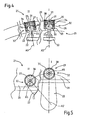
- figure 4 is a frontal view of a detail with parts removed for clarity and parts in section, of a detail in figure 2 in a first operative position I and a second operative position II; and
- figure 5 is a side view of a detail with parts removed for clarity and parts in section, of the detail in figure 2 in a first operative position I and a second operative position II.
- With reference to figure 1, it is indicated as a whole by 1 a compressor of the axial type which extends along an axis A1 and comprises a first stage 2; a second stage 3; and a shaft 4 which extends along axis A1 and is turnable about axis A1.
Compressor 1 comprises a casing C having an essentially tapered shape in which a flow of air is conveyed. The first stage 2 comprises a first fixed stage 5, and a first impeller 6, which is arranged directly downstream of the first fixed stage 5 and is fitted on shaft 4; the second stage 3 comprises a secondfixed stage 7 and an impeller 8, which is arranged directly downstream of the secondfixed stage 7 and is keyed on shaft 4. The first fixed stage 5 comprises an inner ring 9, anouter ring 10 coaxial with inner ring 9, and a plurality ofvanes 11, each of which extends between the inner ring 9 and theouter ring 10. - The second
fixed stage 7 comprises aninner ring 12 extending about the first axis A1; and anouter ring 13 arranged aboutinner ring 12 and coaxial withinner ring 12; and a plurality ofvanes 14, each of which extends betweeninner ring 12 andouter ring 13 and is turnable about an axis A2, which is arranged in an essentially radial direction with respect to the first axis A1 and betweeninner ring 12 andouter ring 13. Similarly, each of thevanes 11 is adjustable about an axis A3 arranged in essentially radial direction with respect to axis A1. -
Vanes 14 are adjustable about the corresponding axis A2 in unison and independently from the firstadjustable vanes 11. For this purpose and with reference to figure 2, eachvane 14 is turnably fitted toinner ring 12 andouter ring 13. In the case in point in figure 2, eachvane 14 presents twopins respective seats inner ring 12 and in theouter ring 13. -
Compressor 1 comprises anadjusting device 19, which comprises: anadjustment ring 20, which extends aboutouter ring 13 and is turnably mounted about first axis A1; a plurality ofball joints 21, each of which is fitted onadjustment ring 20; a plurality oflevers 22, each of which is fixed to apin 16 of acorresponding vane 14; and a plurality ofpins 23, each of which is integral with acorresponding lever 22 and is slidingly coupled to acorresponding ball joint 21. - Each
vane 14,corresponding lever 22, andcorresponding pin 23 are connected so as to form a rigid element.Lever 22 has a first end fixed topin 16 of thecorresponding vane 14 and is arranged perpendicularly to axis A2, and a second end which is fixed to thecorresponding pin 23, which is essentially parallel to axis A2. - The
adjustment ring 20 is fitted on a plurality of bearings 24 (only one of which is shown in figure 2), which are evenly distributed about axis A1 and about casing C and are fitted onrespective supports 25 fixed to casingC. Adjustment ring 20 has atoothed segment 26 and a plurality ofseats 27 uniformly distributed about axis A1.Adjustment ring 20 rests onbearings 25, which in addition to ensuring low-friction rotation ofadjustment ring 20 about axis A1, allowadjustment ring 20 to slide in a direction parallel to axis A1 with respect tobearings 24. - Adjusting
device 19 further comprises adrive member 28 adapted to turn apinion 29, which turns about an axis A4 parallel to axis A1 and engages thetoothed segment 26 to selectively turn in one direction or in the opposite direction of theadjustment ring 20. - With reference to figure 3, each
seat 27 extends about an axis A5 perpendicular to axis A1 and is formed in the thickness ofadjustment ring 20, is a through-hole and presents an annular locator wall. - With reference to figure 4, each
ball joint 21 comprises a spherical body 3 provided with a through-hole 31 (fig. 4) for slidingly accommodatingcorresponding pin 23; and ahousing element 32 of thespherical body 30, which comprises: a first bushing 33 (fig. 4) provided with a face adapted to be coupled by shape with thespherical body 30; asecond bushing 34 provided with a face adapted to be coupled by shape with thespherical body 30; andsprings 35 for elastically fastening thespherical body 30 between the first andsecond bushings - With reference to figure 4,
housing element 32 is essentially cup-shaped and comprises aside wall 36 provided with an outer threading, and a bottom wall which is essentially defined by first bushing 33. Eachhousing element 32 is fastened in a corresponding (threaded)seat 17 ofadjustment ring 20. -
First bushing 33 presents a through-hole for allowing the insertion of acorresponding pin 23, whilesecond bushing 34 is provided with a through-hole for allowing the passage ofpin 23, is capable of sliding along thehousing element 32 and is guided by theside wall 36. -
Housing element 32 comprises aplate 37, which is fixed withinside wall 36 so as to form a locator for the elastic means which are compressed betweenplate 37 and thesecond bushing 34; and a snap ring 38 (figures 3 and 5) engaged in an annular seat arranged alongcylindrical wall 36 to lockplate 37. - In the case in point in figure 4,
springs 35 are counterpoised Belleville springs. - Each
housing element 32 has an essentially cylindrical shape and is fastened in a corresponding appropriately threadedseat 27 ofadjustment ring 20.First bushing 33 is abuttingly arranged against the annular locator wall ofseat 27, while correspondingspherical body 30 is slidingly coupled to acorresponding pin 23. - In use,
adjustment ring 20 is selectively turned about axis A1 in both directions of rotation by means ofdrive member 28 andpinion 29 to determine the simultaneous and agreeing rotation of allvanes 14 about their axes A2 independently fromvanes 11. - With reference to a
single vane 14 and to figures 4 and 5, the rotations ofadjustment ring 20 are minor about a first operative reference position shown in figures 4 and 5 and indicated byI. Adjustment ring 20 may take a plurality of operative positions about the first operative reference position I. A second operative position is shown by II in figures 4 and 5. As may be noted in figures 4 and 5, the rotation of theadjustment ring 20 between the first operative position I and the second operative position II determines at the same time: - a) a rotation of lever about axis A2;
- b) a rotation of
vane 14 about axis A2 due to the rotation oflever 22; - c) a shift of
adjustment ring 20 in a direction parallel to axis A1 with respect to bearing 24 due to the fact that the distance between axis A2 and corresponding axis A5 ofseat 27 ofadjustment ring 20 is reduced in direction parallel to axis A1; - d) a sliding of
pin 23 within thespherical body 30 caused by the reduction of the distance betweenlever 22 andadjustment ring 20; and - e) a rotation of
spherical body 30 with respect to the first andsecond bushings pin 23 within the spherical body. - In other words, the adjusting
device 19 is a kinematic system with a single degree of freedom and therefore the shift of an element of the kinematic chain determines the shift of the other elements of the kinematic chain. - According to an embodiment not shown in the attached figures,
pin 23 is perpendicular to corresponding axis A2; axis A5 ofcorresponding seat 27 is parallel to axis A1; and lever 22 slides along axis A2 with respect tocorresponding vane 14. According to this embodiment (not shown),adjustment ring 20 may be secured so as to prevent shifts along axis A1. - In addition to the advantages described above, the
compressor 1 described and claimed is particularly advantageous because adjustingdevice 19 does not require specific structural changes which respect to a fixed stage compressor provided with non-adjustable vanes: indeed, adjustingdevice 19 requiresseats inner ring 12 and inouter ring 13 and to fix supports 25 ofbearings 24 on casing C. Some additional mechanical machining is therefore required. Furthermore, adjustingdevice 19 according to the present invention is compact in size.
Claims (19)
- A gas turbine compressor comprises a first fixed stage (5) comprising a plurality of first adjustable vanes (11) and further fixed stage (7), which comprises an inner ring (12) extending about a first axis (A1); an outer ring (13) arranged about the inner ring (12) and coaxial with the inner ring (12); and a plurality of second adjustable vanes (14), each of which extends along a second axis (A2) in an essentially radial direction with respect to the first axis (A1) and between the inner ring (12) and the outer ring (13); the compressor being characterised in that each of the second vanes (14) is adjustable about the corresponding second axis (A2) independently from the first adjustable vanes (11).
- A compressor according to claim 1, characterised in that it comprises an adjusting device (19) adapted to solely adjust the orientation of the second vanes (14) and comprising: a plurality of levers (22), each of which is fixed to a corresponding second vane (14) and is turnable about the second axis (A2) to adjust said second vane (14); an adjustment ring (20) turnable about the first axis (A1); and a plurality of ball joints (21), each of which is adapted to connect a corresponding lever (22) to the adjustment ring (20).
- A compressor according to claim 3, characterised in that it comprises a casing (C) and in that the adjustment ring (20) is arranged about said casing (C).
- A compressor according to claim 3, characterised in that the adjustment ring (20) is fitted on bearings (24) fitted on supports (25) fixed to casing (C).
- A compressor according to one of the claims from 2 to 4, characterised in that each lever (22) is integral with a pin (23); each ball joint (21) being slidingly engaged by corresponding pin (23) along pin (23) itself.
- A compressor according to claim 5, characterised in that each lever (22) is perpendicular to corresponding axis (A2); each pin (23) being essentially parallel to corresponding axis (A2).
- A compressor according to claim 6, characterised in that each vane (14) forms a single rigid element with corresponding lever (22) and corresponding pin (23).
- A compressor according to one of the claims from 5 to 7, characterised in that each ball joint (21) comprises a spherical body (30) provided with a through-hole (31) to slidingly accommodate corresponding pin (23).
- A compressor according to any one of the claims from 2 to 8, characterised in that said adjustment ring (20) is mobile in a direction parallel to the first axis (A1) .
- A compressor according to any one of the preceding claims, characterised in that each ball joint (21) comprises: a spherical body (30) coupled to a corresponding lever (22); and a housing element (32) of said spherical body (30); said housing element (32) being fixed to said adjustment ring (20).
- A compressor according to claim 10, characterised in that each housing element (32) comprises: a first bushing (33) provided with a face adapted to be coupled by shape with the spherical body (30); a second bushing (34) provided with a face adapted to be coupled by shape with spherical body (30); and elastic means (35) for elastically fastening spherical body (30) between the first and second bushings (33, 34).
- A compressor according to claim 11, characterised in that each housing element (32) comprises a cylindrical side wall (36) integral with the first bushing (33); the second bushing (34) being mobile within said side wall (36) and being guided by said side wall (36).
- A compressor according to claim 12, characterised in that each ball joint (21) comprises a plate (37) fixed within side wall (36) so as to form a locator for elastic means (35) which are arranged between said plate (37) and the second bushing (38).
- A compressor according to claim 13, characterised in that said elastic means (35) are Belleville springs.
- A compressor according to claim 14, characterised in that said Belleville springs are reciprocally counterpoised.
- A compressor according to any of the preceding claims from 12 to 15, characterised in that each ball joint (21) comprises a snap ring (38) engaged in an annular seat arranged within side wall (36) to lock said plate (37).
- A compressor according to any of the preceding claims from 2 to 16, characterised in that adjustment ring (20) comprises a plurality of seats (27) uniformly arranged about the first axis (A1), each ball joint (21) being fixed into a corresponding seat (27).
- A compressor according to any one of the preceding claims from 2 to 17, characterised in that it comprises a pinion (29) selectively turnable about a third axis (A4) parallel to the first axis (A1) ; adjustment ring (20) comprising a toothed segment (26) meshing with said pinion (29).
- A compressor according to any one of the preceding claims, characterised in that said further fixed stage (3) is the second fixed stage.
Priority Applications (4)
| Application Number | Priority Date | Filing Date | Title |
|---|---|---|---|
| EP06425408A EP1867877A1 (en) | 2006-06-16 | 2006-06-16 | Gas turbine compressor |
| JP2009514816A JP2009540210A (en) | 2006-06-16 | 2007-06-15 | Gas turbine compressor |
| PCT/EP2007/055982 WO2007144430A1 (en) | 2006-06-16 | 2007-06-15 | Gas turbine compressor |
| US12/304,871 US8075253B2 (en) | 2006-06-16 | 2007-06-15 | Gas turbine compressor |
Applications Claiming Priority (1)
| Application Number | Priority Date | Filing Date | Title |
|---|---|---|---|
| EP06425408A EP1867877A1 (en) | 2006-06-16 | 2006-06-16 | Gas turbine compressor |
Publications (1)
| Publication Number | Publication Date |
|---|---|
| EP1867877A1 true EP1867877A1 (en) | 2007-12-19 |
Family
ID=37622050
Family Applications (1)
| Application Number | Title | Priority Date | Filing Date |
|---|---|---|---|
| EP06425408A Withdrawn EP1867877A1 (en) | 2006-06-16 | 2006-06-16 | Gas turbine compressor |
Country Status (4)
| Country | Link |
|---|---|
| US (1) | US8075253B2 (en) |
| EP (1) | EP1867877A1 (en) |
| JP (1) | JP2009540210A (en) |
| WO (1) | WO2007144430A1 (en) |
Cited By (1)
| Publication number | Priority date | Publication date | Assignee | Title |
|---|---|---|---|---|
| US8251646B2 (en) | 2008-04-30 | 2012-08-28 | Rolls-Royce Deutschland Ltd & Co Kg | Rotating unit for an axial-flow compressor |
Families Citing this family (8)
| Publication number | Priority date | Publication date | Assignee | Title |
|---|---|---|---|---|
| US8714916B2 (en) * | 2010-09-28 | 2014-05-06 | General Electric Company | Variable vane assembly for a turbine compressor |
| US20120134783A1 (en) * | 2010-11-30 | 2012-05-31 | General Electric Company | System and method for operating a compressor |
| CN102606223B (en) * | 2011-01-24 | 2014-12-17 | 中国石油化工集团公司 | Flue gas turbine |
| US8909454B2 (en) * | 2011-04-08 | 2014-12-09 | General Electric Company | Control of compression system with independently actuated inlet guide and/or stator vanes |
| JP5747703B2 (en) * | 2011-07-13 | 2015-07-15 | 株式会社Ihi | Turbo compressor |
| EP2971596B1 (en) | 2013-03-10 | 2020-07-15 | Rolls-Royce Corporation | Gas turbine engine and corresponding method |
| CN113803274B (en) * | 2021-11-19 | 2022-03-04 | 中国航发上海商用航空发动机制造有限责任公司 | Axial compressor and turbofan engine |
| DE102024002279A1 (en) * | 2024-07-12 | 2026-01-15 | MTU Aero Engines AG | Turbomachinery adjusting ring assembly |
Citations (7)
| Publication number | Priority date | Publication date | Assignee | Title |
|---|---|---|---|---|
| EP0274931A2 (en) * | 1986-12-17 | 1988-07-20 | Societe Nationale D'etude Et De Construction De Moteurs D'aviation "Snecma" | Adjusting device for the stator vanes of a turbo machine |
| EP0381399A2 (en) * | 1989-02-02 | 1990-08-08 | Hitachi, Ltd. | Vane controller |
| FR2688827A1 (en) * | 1992-03-18 | 1993-09-24 | Snecma | Variable-pitch stator vane control system for a turbojet |
| EP0795681A1 (en) * | 1996-03-14 | 1997-09-17 | Societe Nationale D'etude Et De Construction De Moteurs D'aviation "Snecma" | Actuation mechanism for variable inlet vanes in turbomachine compressor |
| EP1031703A2 (en) * | 1999-02-23 | 2000-08-30 | ROLLS-ROYCE plc | Operating arrangements for stator vanes |
| GB2399865A8 (en) * | 2003-03-28 | 2005-05-16 | Rolls Royce Plc | Improvements in or relating to control of variablestator vanes in a gas turbine engine |
| GB2410530A (en) * | 2004-01-27 | 2005-08-03 | Rolls Royce Plc | Electrically actuated stator vane arrangement |
Family Cites Families (6)
| Publication number | Priority date | Publication date | Assignee | Title |
|---|---|---|---|---|
| JPS5979099A (en) * | 1982-10-27 | 1984-05-08 | Hitachi Ltd | Stationary blade attaching angle changing device in axial flow machine |
| JPH0462399U (en) * | 1990-10-01 | 1992-05-28 | ||
| US5165845A (en) * | 1991-11-08 | 1992-11-24 | United Technologies Corporation | Controlling stall margin in a gas turbine engine during acceleration |
| GB9421047D0 (en) * | 1994-10-11 | 1994-12-07 | Ricardo Aerospace Ltd | Turbines |
| JPH11210699A (en) * | 1998-01-30 | 1999-08-03 | Mitsubishi Heavy Ind Ltd | Setting method of variable stationary vane angle in axial flow compressor |
| FR2858371B1 (en) * | 2003-07-31 | 2005-09-30 | Snecma Moteurs | IMPROVED DEVICE FOR SETTING RECTIFIERS OF A TURBOJET COMPRESSOR |
-
2006
- 2006-06-16 EP EP06425408A patent/EP1867877A1/en not_active Withdrawn
-
2007
- 2007-06-15 WO PCT/EP2007/055982 patent/WO2007144430A1/en not_active Ceased
- 2007-06-15 JP JP2009514816A patent/JP2009540210A/en active Pending
- 2007-06-15 US US12/304,871 patent/US8075253B2/en not_active Expired - Fee Related
Patent Citations (7)
| Publication number | Priority date | Publication date | Assignee | Title |
|---|---|---|---|---|
| EP0274931A2 (en) * | 1986-12-17 | 1988-07-20 | Societe Nationale D'etude Et De Construction De Moteurs D'aviation "Snecma" | Adjusting device for the stator vanes of a turbo machine |
| EP0381399A2 (en) * | 1989-02-02 | 1990-08-08 | Hitachi, Ltd. | Vane controller |
| FR2688827A1 (en) * | 1992-03-18 | 1993-09-24 | Snecma | Variable-pitch stator vane control system for a turbojet |
| EP0795681A1 (en) * | 1996-03-14 | 1997-09-17 | Societe Nationale D'etude Et De Construction De Moteurs D'aviation "Snecma" | Actuation mechanism for variable inlet vanes in turbomachine compressor |
| EP1031703A2 (en) * | 1999-02-23 | 2000-08-30 | ROLLS-ROYCE plc | Operating arrangements for stator vanes |
| GB2399865A8 (en) * | 2003-03-28 | 2005-05-16 | Rolls Royce Plc | Improvements in or relating to control of variablestator vanes in a gas turbine engine |
| GB2410530A (en) * | 2004-01-27 | 2005-08-03 | Rolls Royce Plc | Electrically actuated stator vane arrangement |
Cited By (1)
| Publication number | Priority date | Publication date | Assignee | Title |
|---|---|---|---|---|
| US8251646B2 (en) | 2008-04-30 | 2012-08-28 | Rolls-Royce Deutschland Ltd & Co Kg | Rotating unit for an axial-flow compressor |
Also Published As
| Publication number | Publication date |
|---|---|
| US8075253B2 (en) | 2011-12-13 |
| WO2007144430A1 (en) | 2007-12-21 |
| US20090208329A1 (en) | 2009-08-20 |
| JP2009540210A (en) | 2009-11-19 |
Similar Documents
| Publication | Publication Date | Title |
|---|---|---|
| US8075253B2 (en) | Gas turbine compressor | |
| US7771161B2 (en) | Adjustable guide device | |
| US2999630A (en) | Compressor | |
| US10711688B2 (en) | Variable flow rate valve mechanism and turbocharger | |
| CN1865740B (en) | Motor-operated valve | |
| JP5911863B2 (en) | Device for controlling the pivot blades of a turbomachine | |
| US6779971B2 (en) | Turbine | |
| EP2818666B1 (en) | Turbocharger with turbine nozzle vanes and an annular rotary bypass valve | |
| JPS62258124A (en) | Link mechanism for displacing stator vane integral ring in circumferential direction | |
| US10641125B2 (en) | Nozzle drive mechanism, turbocharger, and variable-capacity turbocharger | |
| CN104813036A (en) | Centrifugal compressor | |
| US20100126168A1 (en) | Turbocharger with variable turbine nozzle actuated by hydraulic and mechanical spring forces | |
| CN1497148B (en) | Method and apparatus for controlling fluid flow in a gas turbine engine | |
| US20180328271A1 (en) | Nozzle drive mechanism, turbocharger, variable capacity turbocharger | |
| ES2285356T3 (en) | GUIDE SYSTEM OF THE EXTERNAL PIVOT OF A WING WITH VARIABLE STREET ANGLE, OF TURBOMAQUINA STATOR. | |
| CN114270050B (en) | Rocker arm for a variable adjustment device of a turbomachine | |
| EP1620638A1 (en) | Control valve and parts of a turbocharger and a turbocharger boosting system comprising the same | |
| CN112555194B (en) | Volute assembly and turbocharger | |
| CN117287420A (en) | Stator blade adjustment mechanism and aero-engine | |
| JP5804481B2 (en) | Actuator for exhaust gas turbocharger | |
| GB2392956A (en) | Controlling inlet to turbocharger turbine | |
| CN114278615B (en) | Flexibly connected diffuser structure based on cam transmission | |
| US11906053B2 (en) | Valve device and method for manufacturing the same | |
| JP2020531723A (en) | Variable guide mechanism for turbines, turbines for exhaust gas turbochargers, and exhaust gas turbochargers | |
| JP2018179231A (en) | Valve positioner |
Legal Events
| Date | Code | Title | Description |
|---|---|---|---|
| PUAI | Public reference made under article 153(3) epc to a published international application that has entered the european phase |
Free format text: ORIGINAL CODE: 0009012 |
|
| AK | Designated contracting states |
Kind code of ref document: A1 Designated state(s): AT BE BG CH CY CZ DE DK EE ES FI FR GB GR HU IE IS IT LI LT LU LV MC NL PL PT RO SE SI SK TR |
|
| AX | Request for extension of the european patent |
Extension state: AL BA HR MK YU |
|
| 17P | Request for examination filed |
Effective date: 20080618 |
|
| AKX | Designation fees paid |
Designated state(s): AT BE BG CH CY CZ DE DK EE ES FI FR GB GR HU IE IS IT LI LT LU LV MC NL PL PT RO SE SI SK TR |
|
| STAA | Information on the status of an ep patent application or granted ep patent |
Free format text: STATUS: THE APPLICATION IS DEEMED TO BE WITHDRAWN |
|
| 18D | Application deemed to be withdrawn |
Effective date: 20130103 |