EP1867519A2 - Tool for extracting the plug socket in tubular outlets - Google Patents
Tool for extracting the plug socket in tubular outlets Download PDFInfo
- Publication number
- EP1867519A2 EP1867519A2 EP07380100A EP07380100A EP1867519A2 EP 1867519 A2 EP1867519 A2 EP 1867519A2 EP 07380100 A EP07380100 A EP 07380100A EP 07380100 A EP07380100 A EP 07380100A EP 1867519 A2 EP1867519 A2 EP 1867519A2
- Authority
- EP
- European Patent Office
- Prior art keywords
- tool
- socket
- pins
- plug socket
- extracting
- Prior art date
- Legal status (The legal status is an assumption and is not a legal conclusion. Google has not performed a legal analysis and makes no representation as to the accuracy of the status listed.)
- Granted
Links
Images


Classifications
-
- H—ELECTRICITY
- H01—ELECTRIC ELEMENTS
- H01R—ELECTRICALLY-CONDUCTIVE CONNECTIONS; STRUCTURAL ASSOCIATIONS OF A PLURALITY OF MUTUALLY-INSULATED ELECTRICAL CONNECTING ELEMENTS; COUPLING DEVICES; CURRENT COLLECTORS
- H01R13/00—Details of coupling devices of the kinds covered by groups H01R12/70 or H01R24/00 - H01R33/00
- H01R13/62—Means for facilitating engagement or disengagement of coupling parts or for holding them in engagement
- H01R13/629—Additional means for facilitating engagement or disengagement of coupling parts, e.g. aligning or guiding means, levers, gas pressure electrical locking indicators, manufacturing tolerances
- H01R13/633—Additional means for facilitating engagement or disengagement of coupling parts, e.g. aligning or guiding means, levers, gas pressure electrical locking indicators, manufacturing tolerances for disengagement only
Definitions
- the present invention relates to a tool which has been especially designed for extracting the plug socket in tubular outlets, especially in those forming part of the electric lighter of automotive vehicles, the evident purpose of which is the disassembly of said sockets for repairing or replacing them.
- the object of the invention is to achieve a reliable tool which ensures the extraction of a plug socket of the type mentioned above virtually instantaneously.
- the wall of the sockets has anchoring windows which house external fastening clamps, as well as retention shapes or windows for retaining the outlet or electric lighter.
- the tool proposed by the invention resolves in a fully satisfactory manner the drawbacks described above, ensuring full operative effectiveness for such tool.
- the tool of the invention focuses its features on the fact that within the mentioned sleeve, the device carrying the pins for unlocking and dragging the plug socket incorporates a cylindrical cam integral with the handle of the tool, but it is able to rotate a certain angle in relation to the sleeve carrying the mentioned pins.
- said cam is inoperative in relation to the pins when introducing the tool inside the plug socket, whereas a subsequent rotation provided to the handle, once the pins are located in their housings in the plug socket, causes said pins to be supported on the cam, whereby the radial retraction thereof is absolutely impossible, and therefore the accidental decoupling of the tool and the plug socket is also impossible until the complete extraction of latter occurs, at which time rotating the cam in the opposite direction allows the decoupling.
- this relative rotation movement between the sleeve and the cam is carried out as a result of the existence at the closed bottom of said sleeve, the end opposite to its pins, of a central hole traversed by a shaft relating the cam with the handle, as well as the existence of a second eccentric, slit-shaped hole with the curve corresponding to its spacing from said shaft, being incorporated therein a pivot which functions as a stop for the angular movement on the slit-shaped hole or guide, allowing a rotational angle of preferably 90°.
- the invention therefore provides a tool which allows carrying out in an easy, fast and safe manner the disassembly or extraction of the plug socket in tubular- shaped outlets of the type described.
- the tool consists of an assembly of pins (5) and (6), located according to equiangularly distributed generating lines of an imaginary cylinder, which pins are connected at one of their ends and as one piece to a common considerably disc-shaped core (7), and at their other end ending in tabs (8) and (9), respectively, intended for acting respectively on the shapes (3) and (4) the plug socket.
- the one-piece assembly formed by the pins (5) and (6) is fixed at its end opposite to the tabs (8) and (9) to a handle (10), being axially integral therewith, functioning in an inner space defined by the pins (5) and (6) a cylindrical cam (11) which the invention is essentially based on, which cam, as can be especially seen in Figure 6, is able to act on the pins (5) and (6) by means of its angular or rotational movement, and accordingly project outwardly and firmly stabilize the tabs (8) and (9) in a locking position on the anchoring windows (3) and the retention windows or shapes (4) of the plug socket, ensuring the unlocking of the external fastening clamps (12), as shown in Figure 7, and the locking of the tabs (9) in the retention shapes (4), as shown in turn in Figure 8.
- said cam is integral with the handle (10) through a central shaft (13), as can be seen especially in Figure 5, this cam (11) and handle (10) assembly being able to rotate in relation to the sleeve (7-5-6) with limited movement, specifically limited by a lug (14) projecting from the inner base of the cam (2) or, as in the embodiment shown in Figure 5, from the corresponding base of the handle (10), and functioning in a groove (15) in the base (7) of the sleeve (5-6).
- Figure 7 shows how, after introducing the tool in the tubular plug socket, given a possible ineffectiveness of the tabs (8), such that the external clamps (12) maintain a locking situation on the rear edge (14) of the windows (3), the radial pressure of the cam (11) on the pins (5) when the handle (10) is rotated would force said external clamps (12) to move until the windows (3) are completely freed, and in a similar manner, as can in turn be inferred from Figure 8, due to a possible tendency of the tabs (9) of the tool to decouple from the shapes (4) of the tubular plug socket due to the radial retraction of the pins (6), this retraction would be impossible due to the support of the cylindrical cam (11) on said pins (6).
Landscapes
- Manufacturing Of Electrical Connectors (AREA)
- Coupling Device And Connection With Printed Circuit (AREA)
- Hand Tools For Fitting Together And Separating, Or Other Hand Tools (AREA)
Abstract
Description
- The present invention relates to a tool which has been especially designed for extracting the plug socket in tubular outlets, especially in those forming part of the electric lighter of automotive vehicles, the evident purpose of which is the disassembly of said sockets for repairing or replacing them.
- The object of the invention is to achieve a reliable tool which ensures the extraction of a plug socket of the type mentioned above virtually instantaneously.
- As is well known, the vast majority of automobiles incorporate in the dashboard or in any other suitable and easy to access area an embedded tubular plug socket, such that only the outline of its opening is visible, this plug socket usually being usable to provide power to the electric lighter of the vehicle, although other devices can be coupled thereto which are provided with a suitable connector, such as for example mobile telephone chargers, navigating devices, flashlights, etc.
- To fix these plug sockets to the dashboard of the vehicle, the wall of the sockets has anchoring windows which house external fastening clamps, as well as retention shapes or windows for retaining the outlet or electric lighter.
- When this type of outlets malfunction, the disassembly of the socket is complicated because it is necessary to withdraw the external fastening clamps, such that the socket is released and can be extracted from the housing in which it is assembled, simultaneously pulling on the plug socket, i.e. acting simultaneously on two groups of elements with two different instruments, which involves a complicated and tedious operation, so much so that on many occasions it is necessary to access the rear part of the dashboard or area in which the plug socket is assembled.
- In trying to solve this problem, the applicant of this patent is the holder of utility model U200502845, which discloses a tool for extracting the socket of tubular outlets, carried out in a type of a "plug-in" sleeve in the tubular base, extending through one of its ends into a hand grip and incorporating at its other end a series of independent axial pins, some of which are intended to enter the retention windows or shapes for retaining the socket, and others in the anchoring windows thereof, such that when the tool is introduced in the plug socket, and when the tool reaches its limit position, the pins thereof act on the fastening clamps, moving them out of the windows and causing the socket to be released, while at the same time other pins are coupled to the retention shapes and allows extracting the plug socket by means of pulling on the tool.
- This solution, which is perfectly valid from the theoretical point of view, in practice has functional problems derived from the fact that many times said pins are not able to remain stable by themselves in their working position, such that sometimes the fastening clamps are not completely out of the windows, whereby the effective release situation of the plug socket does not occur, and other times the pins that have to act on the retention shapes are not duly inserted in such shapes and, when pulling on the tool, slide with respect to the plug socket without causing the extraction thereof.
- The tool proposed by the invention resolves in a fully satisfactory manner the drawbacks described above, ensuring full operative effectiveness for such tool.
- To that end, more specifically and based on a basic structure similar to that of the aforementioned utility model, the tool of the invention focuses its features on the fact that within the mentioned sleeve, the device carrying the pins for unlocking and dragging the plug socket incorporates a cylindrical cam integral with the handle of the tool, but it is able to rotate a certain angle in relation to the sleeve carrying the mentioned pins. More specifically, said cam is inoperative in relation to the pins when introducing the tool inside the plug socket, whereas a subsequent rotation provided to the handle, once the pins are located in their housings in the plug socket, causes said pins to be supported on the cam, whereby the radial retraction thereof is absolutely impossible, and therefore the accidental decoupling of the tool and the plug socket is also impossible until the complete extraction of latter occurs, at which time rotating the cam in the opposite direction allows the decoupling.
- According to another feature of the invention this relative rotation movement between the sleeve and the cam is carried out as a result of the existence at the closed bottom of said sleeve, the end opposite to its pins, of a central hole traversed by a shaft relating the cam with the handle, as well as the existence of a second eccentric, slit-shaped hole with the curve corresponding to its spacing from said shaft, being incorporated therein a pivot which functions as a stop for the angular movement on the slit-shaped hole or guide, allowing a rotational angle of preferably 90°.
- The invention therefore provides a tool which allows carrying out in an easy, fast and safe manner the disassembly or extraction of the plug socket in tubular- shaped outlets of the type described.
- To complement the description which is being made and for the purpose of aiding to better understand the features of the invention according to a preferred practical embodiment thereof, a set of drawings is attached as an integral part of said description which with an illustrative and non-limiting manner shows the following:
- Figure 1 shows a perspective view of a tool for extracting plug sockets in tubular outlets, carried out according to the object of the present invention.
- Figure 2 shows another perspective view of the same tool from a perspective opposite to that of the previous figure, but the handle of the tool has been eliminated in order to more clearly show its structure.
- Figure 3 shows a partial perspective view of a plug socket for tubular outlets, showing the tool of the previous figures, also partially, coupled thereto.
- Figure 4 shows another perspective view of the assembly shown in the previous figure, from a perspective opposite to that of said figure and fully showing both the tool and the plug socket.
- Figure 5 shows a side elevational and longitudinal and diametric section view of the assembly shown in the previous figure.
- Figure 6 shows an axial view of the tool from its end opposite to its handle.
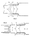
- Figures 7 and 8 show respective schematic longitudinal section views of the plug socket with the extraction tool introduced therein, according to section lines A-A and B-B of Figure 3, respectively.
- In view of the described figures and especially Figures 3 and 4, it can be seen how the tool proposed by the invention is applied to plug sockets (1) assembled on the dashboard (2) of the vehicle or on any other suitable area thereof, said socket (1) being provided on its wall with anchoring windows (3), generally two in number, located in diametrically opposing positions, and two other retention windows or shapes (4), also located in diametrically opposing positions and shifted 90° in relation to the aforementioned windows, for the lighter or outlet in question.
- The tool consists of an assembly of pins (5) and (6), located according to equiangularly distributed generating lines of an imaginary cylinder, which pins are connected at one of their ends and as one piece to a common considerably disc-shaped core (7), and at their other end ending in tabs (8) and (9), respectively, intended for acting respectively on the shapes (3) and (4) the plug socket.
- The one-piece assembly formed by the pins (5) and (6) is fixed at its end opposite to the tabs (8) and (9) to a handle (10), being axially integral therewith, functioning in an inner space defined by the pins (5) and (6) a cylindrical cam (11) which the invention is essentially based on, which cam, as can be especially seen in Figure 6, is able to act on the pins (5) and (6) by means of its angular or rotational movement, and accordingly project outwardly and firmly stabilize the tabs (8) and (9) in a locking position on the anchoring windows (3) and the retention windows or shapes (4) of the plug socket, ensuring the unlocking of the external fastening clamps (12), as shown in Figure 7, and the locking of the tabs (9) in the retention shapes (4), as shown in turn in Figure 8.
- To actuate the cam (11), said cam is integral with the handle (10) through a central shaft (13), as can be seen especially in Figure 5, this cam (11) and handle (10) assembly being able to rotate in relation to the sleeve (7-5-6) with limited movement, specifically limited by a lug (14) projecting from the inner base of the cam (2) or, as in the embodiment shown in Figure 5, from the corresponding base of the handle (10), and functioning in a groove (15) in the base (7) of the sleeve (5-6).
- Therefore, as can be seen especially in Figure 6, when the tabs (8) and (9) have reached the windows (3) and (4) of the tubular plug socket, a 90° rotation of the cam (11), limited by the guide defined by the groove or slit (15) and the lug (14) functioning therein, causes a wedging of said tabs in the working position, making the functional failure of the tool absolutely impossible because both the retraction of the retention clamps (12) of the dashboard fixing the plug socket (1) and the locking of said plug socket to the tool for the extraction thereof is secured.
- Figure 7 shows how, after introducing the tool in the tubular plug socket, given a possible ineffectiveness of the tabs (8), such that the external clamps (12) maintain a locking situation on the rear edge (14) of the windows (3), the radial pressure of the cam (11) on the pins (5) when the handle (10) is rotated would force said external clamps (12) to move until the windows (3) are completely freed, and in a similar manner, as can in turn be inferred from Figure 8, due to a possible tendency of the tabs (9) of the tool to decouple from the shapes (4) of the tubular plug socket due to the radial retraction of the pins (6), this retraction would be impossible due to the support of the cylindrical cam (11) on said pins (6).
Claims (2)
- A tool for extracting the plug socket in tubular outlets, especially in outlets forming part of electric lighters in automotive vehicles and having in their wall anchoring windows receiving external fastening clamps, and retention windows or shapes in the socket, of the type carried out in a sleeve closed at one of its ends, the cylindrical surface of which is carried out in two pairs of pins ending in equiangularly distributed tabs, two of them intended to be coupled in the anchoring windows of the outlet and to act on the external fastening clamps for unlocking the socket, and other two intended to act on the retention shapes for dragging and extracting said socket, characterized in that there is arranged inside said sleeve a cylindrical cam actuated from the handle of the tool, which cylindrical cam allows, according to its angular position, retracting the pins from the sleeve during the operation for implementing the tool in the plug socket, and causing the radial propulsion of said pins when it is rotated and supported thereon, securing and locking them in the operative position.
- A tool for extracting the plug socket in tubular outlets according to claim 1, characterized in that the mentioned cam is axially fixed to the handle of the tool with the aid of a shaft centrally traversing the closed base of the sleeve, which base in turn incorporates an arched slit or groove having a concentric trajectory with the mentioned shaft and in the which a pivot functions, said pivot projecting from the cam or from the handle indistinctly, such that said pivot limits the angular movement of the cam and establishes the two extreme operative and inoperative situations thereof.
Applications Claiming Priority (1)
| Application Number | Priority Date | Filing Date | Title |
|---|---|---|---|
| ES200601329U ES1063141Y (en) | 2006-06-08 | 2006-06-08 | TOOL FOR EXTRACTION OF THE PLUG BASE IN TUBULAR POWER OUTLETS |
Publications (3)
| Publication Number | Publication Date |
|---|---|
| EP1867519A2 true EP1867519A2 (en) | 2007-12-19 |
| EP1867519A3 EP1867519A3 (en) | 2009-11-25 |
| EP1867519B1 EP1867519B1 (en) | 2011-06-29 |
Family
ID=37054901
Family Applications (1)
| Application Number | Title | Priority Date | Filing Date |
|---|---|---|---|
| EP20070380100 Not-in-force EP1867519B1 (en) | 2006-06-08 | 2007-04-11 | Tool for extracting the plug socket in tubular outlets |
Country Status (2)
| Country | Link |
|---|---|
| EP (1) | EP1867519B1 (en) |
| ES (2) | ES1063141Y (en) |
Family Cites Families (1)
| Publication number | Priority date | Publication date | Assignee | Title |
|---|---|---|---|---|
| ES1061955Y (en) * | 2005-12-29 | 2006-08-01 | Seat Sa | TOOL FOR EXTRACTION OF THE BASE OF TUBULAR POWER SOCKETS. |
-
2006
- 2006-06-08 ES ES200601329U patent/ES1063141Y/en not_active Expired - Fee Related
-
2007
- 2007-04-11 ES ES07380100T patent/ES2369611T3/en active Active
- 2007-04-11 EP EP20070380100 patent/EP1867519B1/en not_active Not-in-force
Also Published As
| Publication number | Publication date |
|---|---|
| ES1063141U (en) | 2006-10-01 |
| EP1867519A3 (en) | 2009-11-25 |
| ES1063141Y (en) | 2007-01-01 |
| EP1867519B1 (en) | 2011-06-29 |
| ES2369611T3 (en) | 2011-12-02 |
Similar Documents
| Publication | Publication Date | Title |
|---|---|---|
| EP3179148B1 (en) | Lock mechanism for tubular body | |
| JP5154739B2 (en) | Toggle bolt fastener for heavy objects and method of disassembling | |
| US8147173B2 (en) | Adapter for operating a keyhole saw on a driving machine | |
| CA2722450C (en) | Locking mechanism | |
| SE533221C2 (en) | Connection device for media cables | |
| US20090160138A1 (en) | Tool holder for a machine tool, in particular for a hand-held power tool | |
| US9914176B2 (en) | Rotary tool | |
| US20130134684A1 (en) | Electric screwdriver | |
| EP2011697A3 (en) | Flat cable connector with locking clip and centering mechanism | |
| JP6550264B2 (en) | Fastening chuck with fast exchange function and tightening mechanism | |
| EP2745981B1 (en) | Planetary gear alignment and indexing method and associated tool | |
| US12577975B2 (en) | Fastening apparatus and method for fastening components to bolts | |
| JPH11294420A (en) | Auxiliary equipment mounting structure | |
| CN102729225B (en) | Quick clamping mechanism | |
| EP1867519B1 (en) | Tool for extracting the plug socket in tubular outlets | |
| KR20070100906A (en) | Cylinder lock assembly | |
| US7431308B2 (en) | Tool-holding chuck for equipping a rotating machine, provided with sequenced radial and axial locking means | |
| CN111432947A (en) | Sewer cable decoupling tool | |
| CN203684353U (en) | Locking mechanism | |
| EP3209895A1 (en) | Ball pin connector | |
| EP2229509B1 (en) | Nozzle vane and crank arm assembly and assembling method | |
| JP4355075B2 (en) | Steering column anti-theft device for automobile | |
| JP3151636U (en) | Rapid joint structure | |
| CN102345654A (en) | Engagement member with fastening pin and method for interconnecting two components | |
| KR20160003976U (en) | Lockable socket |
Legal Events
| Date | Code | Title | Description |
|---|---|---|---|
| PUAI | Public reference made under article 153(3) epc to a published international application that has entered the european phase |
Free format text: ORIGINAL CODE: 0009012 |
|
| AK | Designated contracting states |
Kind code of ref document: A2 Designated state(s): AT BE BG CH CY CZ DE DK EE ES FI FR GB GR HU IE IS IT LI LT LU LV MC MT NL PL PT RO SE SI SK TR |
|
| AX | Request for extension of the european patent |
Extension state: AL BA HR MK YU |
|
| 17P | Request for examination filed |
Effective date: 20070411 |
|
| PUAL | Search report despatched |
Free format text: ORIGINAL CODE: 0009013 |
|
| AK | Designated contracting states |
Kind code of ref document: A3 Designated state(s): AT BE BG CH CY CZ DE DK EE ES FI FR GB GR HU IE IS IT LI LT LU LV MC MT NL PL PT RO SE SI SK TR |
|
| AX | Request for extension of the european patent |
Extension state: AL BA HR MK RS |
|
| 17Q | First examination report despatched |
Effective date: 20100614 |
|
| AKX | Designation fees paid |
Designated state(s): DE ES FR GB IT |
|
| GRAP | Despatch of communication of intention to grant a patent |
Free format text: ORIGINAL CODE: EPIDOSNIGR1 |
|
| GRAS | Grant fee paid |
Free format text: ORIGINAL CODE: EPIDOSNIGR3 |
|
| GRAA | (expected) grant |
Free format text: ORIGINAL CODE: 0009210 |
|
| AK | Designated contracting states |
Kind code of ref document: B1 Designated state(s): DE ES FR GB IT |
|
| REG | Reference to a national code |
Ref country code: GB Ref legal event code: FG4D |
|
| REG | Reference to a national code |
Ref country code: DE Ref legal event code: R096 Ref document number: 602007015496 Country of ref document: DE Effective date: 20110825 |
|
| REG | Reference to a national code |
Ref country code: ES Ref legal event code: FG2A Ref document number: 2369611 Country of ref document: ES Kind code of ref document: T3 Effective date: 20111202 |
|
| PLBE | No opposition filed within time limit |
Free format text: ORIGINAL CODE: 0009261 |
|
| STAA | Information on the status of an ep patent application or granted ep patent |
Free format text: STATUS: NO OPPOSITION FILED WITHIN TIME LIMIT |
|
| 26N | No opposition filed |
Effective date: 20120330 |
|
| REG | Reference to a national code |
Ref country code: DE Ref legal event code: R097 Ref document number: 602007015496 Country of ref document: DE Effective date: 20120330 |
|
| GBPC | Gb: european patent ceased through non-payment of renewal fee |
Effective date: 20120411 |
|
| REG | Reference to a national code |
Ref country code: FR Ref legal event code: ST Effective date: 20121228 |
|
| PG25 | Lapsed in a contracting state [announced via postgrant information from national office to epo] |
Ref country code: GB Free format text: LAPSE BECAUSE OF NON-PAYMENT OF DUE FEES Effective date: 20120411 |
|
| REG | Reference to a national code |
Ref country code: DE Ref legal event code: R119 Ref document number: 602007015496 Country of ref document: DE Effective date: 20121101 |
|
| PG25 | Lapsed in a contracting state [announced via postgrant information from national office to epo] |
Ref country code: FR Free format text: LAPSE BECAUSE OF NON-PAYMENT OF DUE FEES Effective date: 20120430 Ref country code: IT Free format text: LAPSE BECAUSE OF NON-PAYMENT OF DUE FEES Effective date: 20120411 |
|
| REG | Reference to a national code |
Ref country code: ES Ref legal event code: FD2A Effective date: 20130716 |
|
| PG25 | Lapsed in a contracting state [announced via postgrant information from national office to epo] |
Ref country code: ES Free format text: LAPSE BECAUSE OF NON-PAYMENT OF DUE FEES Effective date: 20120412 |
|
| PG25 | Lapsed in a contracting state [announced via postgrant information from national office to epo] |
Ref country code: DE Free format text: LAPSE BECAUSE OF FAILURE TO SUBMIT A TRANSLATION OF THE DESCRIPTION OR TO PAY THE FEE WITHIN THE PRESCRIBED TIME-LIMIT Effective date: 20121101 |