EP1867473A1 - Functional composite material wherein piezoelectric fiber having metal core is embedded - Google Patents
Functional composite material wherein piezoelectric fiber having metal core is embedded Download PDFInfo
- Publication number
- EP1867473A1 EP1867473A1 EP06715113A EP06715113A EP1867473A1 EP 1867473 A1 EP1867473 A1 EP 1867473A1 EP 06715113 A EP06715113 A EP 06715113A EP 06715113 A EP06715113 A EP 06715113A EP 1867473 A1 EP1867473 A1 EP 1867473A1
- Authority
- EP
- European Patent Office
- Prior art keywords
- composite material
- functional composite
- groove
- metal
- substrate
- Prior art date
- Legal status (The legal status is an assumption and is not a legal conclusion. Google has not performed a legal analysis and makes no representation as to the accuracy of the status listed.)
- Granted
Links
- 229910052751 metal Inorganic materials 0.000 title claims abstract description 102
- 239000002184 metal Substances 0.000 title claims abstract description 102
- 239000002131 composite material Substances 0.000 title claims abstract description 95
- 239000000835 fiber Substances 0.000 title claims abstract description 90
- 239000000758 substrate Substances 0.000 claims abstract description 76
- 238000004519 manufacturing process Methods 0.000 claims abstract description 19
- 229910052782 aluminium Inorganic materials 0.000 claims description 34
- XAGFODPZIPBFFR-UHFFFAOYSA-N aluminium Chemical compound [Al] XAGFODPZIPBFFR-UHFFFAOYSA-N 0.000 claims description 34
- 238000007731 hot pressing Methods 0.000 claims description 26
- RYGMFSIKBFXOCR-UHFFFAOYSA-N Copper Chemical compound [Cu] RYGMFSIKBFXOCR-UHFFFAOYSA-N 0.000 claims description 22
- 229910052802 copper Inorganic materials 0.000 claims description 21
- 239000010949 copper Substances 0.000 claims description 21
- 239000000956 alloy Substances 0.000 claims description 19
- 229910045601 alloy Inorganic materials 0.000 claims description 18
- 238000000034 method Methods 0.000 claims description 16
- 230000007613 environmental effect Effects 0.000 abstract description 4
- 239000000463 material Substances 0.000 description 23
- 239000011159 matrix material Substances 0.000 description 22
- 239000006023 eutectic alloy Substances 0.000 description 14
- 238000002474 experimental method Methods 0.000 description 9
- 238000005516 engineering process Methods 0.000 description 7
- 230000005496 eutectics Effects 0.000 description 6
- 238000006073 displacement reaction Methods 0.000 description 5
- 230000005684 electric field Effects 0.000 description 5
- 150000002739 metals Chemical class 0.000 description 5
- 238000006243 chemical reaction Methods 0.000 description 3
- 230000000052 comparative effect Effects 0.000 description 3
- 230000006378 damage Effects 0.000 description 3
- 239000007791 liquid phase Substances 0.000 description 3
- 238000005259 measurement Methods 0.000 description 3
- 230000008018 melting Effects 0.000 description 3
- 238000002844 melting Methods 0.000 description 3
- 230000008901 benefit Effects 0.000 description 2
- 230000015572 biosynthetic process Effects 0.000 description 2
- 239000004918 carbon fiber reinforced polymer Substances 0.000 description 2
- 230000003247 decreasing effect Effects 0.000 description 2
- 239000003733 fiber-reinforced composite Substances 0.000 description 2
- 229910052745 lead Inorganic materials 0.000 description 2
- 239000000203 mixture Substances 0.000 description 2
- 239000013307 optical fiber Substances 0.000 description 2
- 238000010587 phase diagram Methods 0.000 description 2
- BASFCYQUMIYNBI-UHFFFAOYSA-N platinum Substances [Pt] BASFCYQUMIYNBI-UHFFFAOYSA-N 0.000 description 2
- 239000010935 stainless steel Substances 0.000 description 2
- 229910001220 stainless steel Inorganic materials 0.000 description 2
- 229910052719 titanium Inorganic materials 0.000 description 2
- 230000001131 transforming effect Effects 0.000 description 2
- 229910052726 zirconium Inorganic materials 0.000 description 2
- 230000015556 catabolic process Effects 0.000 description 1
- 239000004020 conductor Substances 0.000 description 1
- 239000011889 copper foil Substances 0.000 description 1
- 230000035080 detection of muscle activity involved in regulation of muscle adaptation Effects 0.000 description 1
- 230000000694 effects Effects 0.000 description 1
- 239000011888 foil Substances 0.000 description 1
- 230000036541 health Effects 0.000 description 1
- 230000006872 improvement Effects 0.000 description 1
- 238000011835 investigation Methods 0.000 description 1
- 238000007733 ion plating Methods 0.000 description 1
- 239000007769 metal material Substances 0.000 description 1
- 238000012544 monitoring process Methods 0.000 description 1
- 230000003287 optical effect Effects 0.000 description 1
- 230000000737 periodic effect Effects 0.000 description 1
- 230000002093 peripheral effect Effects 0.000 description 1
- 239000012071 phase Substances 0.000 description 1
- 238000007747 plating Methods 0.000 description 1
- 230000009467 reduction Effects 0.000 description 1
- 230000004044 response Effects 0.000 description 1
- 238000004544 sputter deposition Methods 0.000 description 1
- 238000007740 vapor deposition Methods 0.000 description 1
Images


Classifications
-
- H10N30/702—
-
- H—ELECTRICITY
- H10—SEMICONDUCTOR DEVICES; ELECTRIC SOLID-STATE DEVICES NOT OTHERWISE PROVIDED FOR
- H10N—ELECTRIC SOLID-STATE DEVICES NOT OTHERWISE PROVIDED FOR
- H10N30/00—Piezoelectric or electrostrictive devices
- H10N30/01—Manufacture or treatment
- H10N30/03—Assembling devices that include piezoelectric or electrostrictive parts
-
- H—ELECTRICITY
- H10—SEMICONDUCTOR DEVICES; ELECTRIC SOLID-STATE DEVICES NOT OTHERWISE PROVIDED FOR
- H10N—ELECTRIC SOLID-STATE DEVICES NOT OTHERWISE PROVIDED FOR
- H10N30/00—Piezoelectric or electrostrictive devices
- H10N30/01—Manufacture or treatment
- H10N30/09—Forming piezoelectric or electrostrictive materials
- H10N30/092—Forming composite materials
-
- H—ELECTRICITY
- H10—SEMICONDUCTOR DEVICES; ELECTRIC SOLID-STATE DEVICES NOT OTHERWISE PROVIDED FOR
- H10N—ELECTRIC SOLID-STATE DEVICES NOT OTHERWISE PROVIDED FOR
- H10N30/00—Piezoelectric or electrostrictive devices
- H10N30/60—Piezoelectric or electrostrictive devices having a coaxial cable structure
-
- H—ELECTRICITY
- H10—SEMICONDUCTOR DEVICES; ELECTRIC SOLID-STATE DEVICES NOT OTHERWISE PROVIDED FOR
- H10N—ELECTRIC SOLID-STATE DEVICES NOT OTHERWISE PROVIDED FOR
- H10N30/00—Piezoelectric or electrostrictive devices
- H10N30/80—Constructional details
- H10N30/85—Piezoelectric or electrostrictive active materials
- H10N30/852—Composite materials, e.g. having 1-3 or 2-2 type connectivity
-
- Y—GENERAL TAGGING OF NEW TECHNOLOGICAL DEVELOPMENTS; GENERAL TAGGING OF CROSS-SECTIONAL TECHNOLOGIES SPANNING OVER SEVERAL SECTIONS OF THE IPC; TECHNICAL SUBJECTS COVERED BY FORMER USPC CROSS-REFERENCE ART COLLECTIONS [XRACs] AND DIGESTS
- Y10—TECHNICAL SUBJECTS COVERED BY FORMER USPC
- Y10T—TECHNICAL SUBJECTS COVERED BY FORMER US CLASSIFICATION
- Y10T428/00—Stock material or miscellaneous articles
- Y10T428/12—All metal or with adjacent metals
- Y10T428/12493—Composite; i.e., plural, adjacent, spatially distinct metal components [e.g., layers, joint, etc.]
- Y10T428/12535—Composite; i.e., plural, adjacent, spatially distinct metal components [e.g., layers, joint, etc.] with additional, spatially distinct nonmetal component
- Y10T428/12611—Oxide-containing component
- Y10T428/12618—Plural oxides
-
- Y—GENERAL TAGGING OF NEW TECHNOLOGICAL DEVELOPMENTS; GENERAL TAGGING OF CROSS-SECTIONAL TECHNOLOGIES SPANNING OVER SEVERAL SECTIONS OF THE IPC; TECHNICAL SUBJECTS COVERED BY FORMER USPC CROSS-REFERENCE ART COLLECTIONS [XRACs] AND DIGESTS
- Y10—TECHNICAL SUBJECTS COVERED BY FORMER USPC
- Y10T—TECHNICAL SUBJECTS COVERED BY FORMER US CLASSIFICATION
- Y10T428/00—Stock material or miscellaneous articles
- Y10T428/249921—Web or sheet containing structurally defined element or component
- Y10T428/249924—Noninterengaged fiber-containing paper-free web or sheet which is not of specified porosity
- Y10T428/249927—Fiber embedded in a metal matrix
Definitions
- the present invention relates to a functional composite material in which a piezoelectric fiber is embedded and a method for manufacturing the same.
- Patent Documents 1 and 2 Examples of conventional technologies of embedding a fiber in a metal matrix material and transforming it into a composite material include Patent Documents 1 and 2 described below.
- Patent Document 1 described below discloses a technology of manufacturing a functional composite material with an optical fiber embedded in a metal matrix material.
- Patent Document 2 described below discloses a technology of manufacturing a functional composite material with a long-fiber reinforced composite material and short-fiber reinforced composite material embedded in a metal matrix material.
- Patent Document 3 discloses a functional composite material with a PZT fiber having a metal core embedded so as to function as a quick response sensor and actuator.
- the PZT fiber having a metal core is a fiber with a piezoelectric material containing elements such as Pb, Zr, Ti formed around the metal core such as Pt.
- Patent Document 1 is designed to embed an optical fiber and not to embed a piezoelectric fiber having a metal core
- Patent Document 2 is designed to embed a reinforced fiber and not to embed a piezoelectric fiber having a metal core.
- a piezoelectric fiber having a metal core is very brittle, furthermore highly reactive with metals such as aluminum and it is extremely difficult to adopt a metal as a matrix material when embedding the piezoelectric fiber having a metal core, and therefore adopting a metal as a matrix has not ever been realized.
- the technology described in Patent Document 3 described above also uses carbon fiber reinforced plastic as a matrix material, which is not a metal.
- the piezoelectric fiber When a piezoelectric fiber having a metal core is used as a sensor or an actuator, the piezoelectric fiber is used with a voltage applied between the metal core inside and a conductive material outside, and therefore the voltage can be applied more effectively and therefore the function as the actuator can be expected to improve dramatically when the piezoelectric fiber is embedded in a metal material than when it is embedded in carbon fiber reinforced plastic.
- the method for manufacturing a functional composite material includes a step of forming an insert layer on a first metal substrate in which a groove is formed, a step of placing a piezoelectric fiber having a metal core on the first metal substrate, and a step of hot-pressing the insert layer between the first substrate and a second substrate using the second substrate. This allows, for the first time, the brittle piezoelectric fiber to be embedded in a metal matrix such as aluminum.
- the above described means more preferably uses, but not limited to, aluminum or an alloy thereof for the first metal substrate and the second metal substrate and uses copper or an alloy thereof for the insert layer.
- Aluminum is a light and high-strength material and a desirable material for the actuator, and use of copper for the insert layer makes it possible to cause a eutectic point to fall below 933 K, which is the melting point of aluminum, lower the temperature of hot pressing and further reduce damage to the piezoelectric fiber.
- the thickness of the aluminum substrate is believed to be decreased approximately 4 times that of the insert layer, and it is thereby possible to manufacture a better functional composite material by setting the depth of the groove within this range.
- setting the depth of the groove to within 7 times can prevent embrittlement (reduction of strength) caused by the insert layer remaining in the matrix as a eutectic alloy even after hot pressing, which is desirable.
- the temperature in the hot-pressing step is preferably set to, but not limited to, higher than 853 K and lower than 893 K. This is because a temperature of 893 K or higher may lead to a rupture of the PZT fiber, while a temperature of 853 K or lower may cause a large quantity of eutectic alloy of aluminum and copper to remain around the piezoelectric fiber reducing the strength as the structural material.
- the pressure in the hot-pressing step is more preferably set to, but not limited to, within a range higher than 1.1 MPa and lower than 4.4 MPa and still more preferably not lower than 1.5 MPa and not higher than 4 MPa.
- the method for manufacturing a functional composite material includes a step of forming an insert layer in a first substrate, a step of forming a groove in the first substrate in which the insert layer is formed, a step of placing a piezoelectric fiber having a metal core on the first substrate in which the groove is formed and a step of hot-pressing a second substrate and the first substrate.
- the first metal substrate and the second metal substrate are more preferably made of, but not limited to, aluminum or an alloy thereof, the insert layer is made of copper or an alloy thereof and the depth of the groove is deeper than the diameter of the piezoelectric fiber placed in the groove by not less than 4 times and not more than 7 times the thickness of the insert layer.
- the first metal substrate and the second metal substrate are more preferably made of, but not limited to, aluminum or an alloy thereof, the insert layer is made of copper or an alloy thereof and the temperature in the hot-pressing step is higher than 853 K and lower than 893 K.
- the hot-pressing step is more preferably performed at, but not limited to, a pressure higher than 1.1 MPa and lower than 4.4 MPa and still more preferably not lower than 1.5 MPa and not higher than 4 MPa.
- a piezoelectric fiber having a metal core is embedded in aluminum or an alloy thereof. This allows the functions as the sensor and the actuator to be exerted.
- Figure 1 shows an outline of steps of manufacturing a functional composite material (hereinafter, referred to as a "functional composite material”) according to this embodiment.
- the steps of manufacturing this functional composite material include a step of forming an insert layer 2 on a first metal substrate 3 ( Figure 1(A)), a step of forming a groove 4 in the first substrate 3 on which the insert layer 2 is formed using a groove forming fiber 1 ( Figure 1(B)), a step of placing a piezoelectric fiber 5 having a metal core 5a in the groove 4 of the first metal substrate 3 ( Figure 1(C)) and a step of hot-pressing the first substrate 3 and a second substrate 6 using the second substrate 6 ( Figure 1(D)).
- the present specification expresses the "first metal substrate” and the "second metal substrate”, but these are naming for the pair of metal substrates for convenience' sake and have not particularly restrictive meanings.
- the present specification expresses the first and second metal substrates which are hot-pressed and bonded together as a "metal matrix material.”
- the thicknesses of the first metal substrate 3 and the second metal substrate 6 are adjustable as appropriate considering the diameter of the piezoelectric fiber 5 to be embedded and the functions as the actuator and not limited, but the thicknesses preferably fall within a range of 0.3 mm to several tens of mm, or more preferably within a range of 0.3 mm to 2 mm from the standpoint of a high-volume and multilayered structure.
- the groove 4 is formed in the first metal substrate 3 and the piezoelectric fiber 5 is placed there.
- Various methods may be used as the method for forming the groove 4, and one of examples is a method whereby a stainless steel fiber corresponding to the depth of the groove to be created is placed on the metal substrate and a pressure is applied thereto to form the groove 4 ( Figure 1(A)).
- the formation of the groove 4 can be performed after forming the insert layer 2 as shown in Figure 1 or directly performed on the surface of the first metal substrate 3 before forming the insert layer 2.
- the “depth of the groove” in the present specification refers to the length from the surface of the first metal substrate 3 in which the groove 4 is formed to the lowest point of the groove 4 at which the groove 4 is formed and when referring to the depth of the groove 4, the thickness of the insert layer 2 is not considered.
- the depth of the groove 4 is adjustable as appropriate according to the diameter or the like of the piezoelectric fiber 5 embedded and not limited, but the depth is more preferably greater than the diameter of the piezoelectric fiber 5 placed in the groove 4 by not less than 4 times and not more than 7 times the thickness of the insert layer 2.
- the depth of the groove can be measured from the cross section of the substrate using an optical microscope or can also be measured using a laser displacement meter.
- the insert layer 2 reacts with those substrates and thereby functions as a bonding layer and also functions as a protection layer by filling the gap between the groove and the piezoelectric fiber.
- copper or an alloy thereof is preferable as a metal for the insert layer 2 though other metals can also be used if they are conductive, and not limited to copper or an alloy thereof.
- the insert layer 2 can be formed using various methods. For example, publicly known ordinary methods such as placing a thin foil on the substrate, a sputtering method, a plating method, a vapor deposition method, an ion plating method can be used therefor.
- the thickness of the insert layer a thickness that allows the first and second metal substrates 3, 6 to be bonded together through hot pressing is required, but the thickness should not be so large as to obstruct the function as the functional material (strength as the structural material) and is preferably, but not limited to, not less than 5 ⁇ m and not more than 20 ⁇ m, for example.
- the piezoelectric fiber 5 having the metal core 5a is a fiber having a structure in which a linear metal core is placed in the vicinity of the center and the periphery thereof is coated with a piezoelectric material, and is preferably, but not limited to, a PZT fiber having a metal core from the standpoint of production.
- the PZT fiber having a metal core is a platinum core coated with a piezoelectric material containing a metal or metals such as Pb, Zr, Ti.
- the cross section of the piezoelectric fiber preferably has, but not limited to, a nearly circular shape in consideration of the distance between the metal matrix and the metal core.
- the diameter of the piezoelectric fiber is, but not particularly limited to, not less than 50 ⁇ m and not more than 1 mm and more preferably within a range of not less than 50 ⁇ m and not more than 0.5 mm and the diameter of the metal core is more preferably within a range of not less than 10 ⁇ m and not more than 100 ⁇ m.
- Figure 3 shows a cross section of the PZT fiber having a metal core as an example.
- the step of hot-pressing the first metal substrate 3 and the second metal substrate 6 between which the insert layer 2 is sandwiched is adjustable as appropriate depending on the material to be selected and the piezoelectric fiber 5a.
- the temperature therefor is preferably, but is not limited to, within a range higher than 853 K and lower than 893 K.
- the melting point can be lowered to 821 K which is the eutectic point when aluminum and copper are used, but too a low temperature may cause a large amount of eutectic alloy to remain in the matrix even after hot pressing and may reduce the function as the functional composite material. Therefore the temperature is preferably higher than 853 K.
- the temperature is preferably less than 893 K.
- the pressure in this case is preferably not lower than a pressure that allows the substrate to be bonded and within a pressure range in which the piezoelectric fiber is not destroyed, preferably not lower than 1.1 MPa and not higher than 4.4 MPa, more preferably not lower than 1.5 MPa and not higher than 4 MPa.
- the duration of hot pressing is preferably within a range not less than 5 minutes and not more than one hour.
- a very brittle piezoelectric fiber, particularly PZT fiber can be embedded in the metal matrix.
- the number of piezoelectric fibers 5 embedded in this functional composite material may be one, but may also be plural to improve the functionality as the functional composite material.
- This cross-sectional view is shown in Figure 4. Since this functional composite material contains the metal core 5a in the piezoelectric fiber 5 and the matrix material is also metal, distortion can be caused in the piezoelectric fiber by applying an electric field between these metals. This distortion acts on the matrix consequently and causes the matrix to operate so as to stretch or shorten the piezoelectric fiber in the direction in which the piezoelectric fiber is deformed.
- a functional composite material according to the present embodiment was actually manufactured.
- aluminum was used for the first and second metal substrates and copper was used for the insert layer.
- Aluminum as the first substrate was assumed to be 1.5 mm in thickness, 15 mm in length and 30 mm in width. A copper foil of 10 ⁇ m in thickness was then overlapped as the insert layer.
- a PZT fiber of approximately 200 ⁇ m in diameter was placed in the groove and a second metal substrate made of aluminum of 1.5 mm in thickness, 15 mm in width, 30 mm in length was hot-pressed for 2.4 ks at a pressure of 2.2 MPa and at 873 K.
- Figure 6 shows a cross-sectional view of the resulting functional composite material.
- the PZT fiber existed satisfactorily without being destroyed and a eutectic alloy was also removed sufficiently, resulting in a good functional composite material.
- FIGS 7(A) and (B) show an outline of the apparatus for this confirming experiment.
- the apparatus for this confirming experiment has a vibration plate 7 (aluminum (A1050P-H24), 200 mm x 50 mm x 1 mm) and a vise 8 to fix this vibration plate 7, and a coil 9 and the functional composite material 10 produced above are further arranged on the vibration plate 7.
- an arbitrary waveform generator 11 and an amplifier 12 are connected to the coil 9. It is possible to cause the vibration plate 7 to vibrate periodically by applying a periodic voltage to the coil 9 to make it interact with a magnet placed so as to face the coil 9.
- Figure 8 shows the result of this measurement.
- a voltage having 15 Hz and amplitude of 10 V is applied to the coil.
- the horizontal axis in Figure 8 shows a time scale and the vertical axis shows an output (voltage).
- Figures 9(A) and 9(B) show an apparatus for this confirming experiment.
- the apparatus for this confirming experiment is the same as that for the above described confirming experiment but differs in that it uses a lock-in amplifier 15 instead of the amplifier 12 and the oscilloscope 14 in Figure 7(B). This result is shown in Figure 10.
- the phase changes by 180 degrees before and after a resonance frequency (around 34.5 Hz) of this functional composite material and it could be thereby confirmed that this functional material generated an output through a piezoelectric effect not by disturbance such as an input voltage.
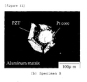
- a functional composite material example with no insert layer was manufactured as a comparative example. Substantially the same structure as that of Functional Composite Material Example 1 was adopted except in that the temperature was set to 873 K and the pressure was set to 16.4 MPa. Figure 11 shows a cross-sectional view thereof. This shows that since no insert layer was formed, the PZT fiber could not withstand a high press pressure and was destroyed completely. It could be confirmed that the formation of the insert layer was indispensable.
- This Example 2 was manufactured under substantially the same condition as that of Functional Composite Material Example 1 except in that the temperature of hot pressing was set to 893 K.
- Figure 12 shows a cross-sectional view of the resulting functional composite material. Though the eutectic alloy was removed sufficiently in this functional composite material, a rupture as shown in Figure 13 was observed. This seems to be attributable to the fact that the high temperature caused the aluminum matrix to soften, and this induced a flow in the direction of the fiber and thereby induced a crack in the piezoelectric material.
- This Example 3 was manufactured under substantially the same condition as that of Functional Composite Material Example 1 except in that the temperature of hot pressing was set to 853 K.
- Figure 14 shows a cross-sectional view of the resulting functional composite material. Though no rupture of the PZT fiber was observed in this functional composite material, it could be confirmed that a large quantity of eutectic alloy remained in the matrix because the temperature was low.
- the hot-pressing temperature was preferably higher than 853 K and lower than 893 K.
- This Example 4 was manufactured under substantially the same condition as that of Functional Composite Material 1 except in that the diameter of the PZT fiber was set to approximately 200 ⁇ m, the depth of the groove was set to 230 ⁇ m and the insert layer was set to 10 ⁇ m.
- Figure 15 shows a cross-sectional view of the resulting functional composite material. It could be confirmed that the PZT fiber was destroyed in this functional composite material. This seems to be attributable to the fact that a eutectic alloy was formed by aluminum and copper, the surface of the aluminum substrate became a liquid phase, and the liquid phase flowed with the result that the depth of the groove decreased, the PZT fiber was directly pushed against the metal substrate and a pressure at more than a tolerable level was applied. That is, it was found that the depth of the groove is preferably larger than the diameter of the PZT fiber by more than 3 times the thickness of the insert layer.
- This Material 5 was manufactured under substantially the same condition as that of Functional Composite Material 4 except in that the depth of the groove was set to 300 ⁇ m.
- Figure 16 shows a cross-sectional view of this functional composite material. It could be confirmed that the PZT fiber having a metal core was sound in this functional composite material. However, since the groove was deep more than necessary, voids remained around the piezoelectric fiber and moreover the eutectic alloy of aluminum and copper could not be effectively removed and allowed to remain. That is, it was found that the depth of the groove is preferably smaller than 10 times the thickness of the insert layer.
- This Material 6 was manufactured under substantially the same condition as that of Functional Composite Material 5 except in that the depth of the groove was set to 280 ⁇ m. It could be confirmed that the PZT fiber having a metal core was sound in this functional composite material. However, since the groove was deep more than necessary as in the case of the above described example, the eutectic alloy of aluminum and copper could not be effectively removed and allowed to remain. That is, it was found that the depth of the groove is preferably smaller than 8 times the thickness of the insert layer.
- This Material 7 was manufactured under substantially the same condition as that of Functional Composite Material 1 except in that the hot-pressing pressure was set to 3.3 MPa.
- the PZT fiber existed satisfactorily without being destroyed as shown in above Figure 6, the eutectic alloy was also removed sufficiently and the material was proven to be a good functional composite material.
- This Material 8 was manufactured under substantially the same condition as that of Functional Composite Material 1 except in that the hot-pressing pressure was set to 4.4 MPa. It could be confirmed that the PZT fiber was destroyed in this functional composite material. This seems to be attributable to the fact that the pressure was too high and it was found that the pressure is preferably lower than 4.4 MPa.
- This Material 9 was manufactured under substantially the same condition as that of Functional Composite Material 1 except in that the hot-pressing pressure was set to 1.1 MPa. It could be confirmed that the eutectic alloy could not be sufficiently discharged out of the material and allowed to remain, and that voids remained around the piezoelectric fiber. This seems to be attributable to the fact that the pressure was too low and that the pressure is preferably higher than 1.1 MPa.
- this embodiment allows a very brittle piezoelectric fiber, PZT fiber in particular, to be embedded in the metal matrix material.
- the insert layer was formed on the first substrate, but it is also possible to form the insert layer only on the second substrate side and perform hot pressing. This prevents the insert layer from being formed in the groove and has an advantage that the adjustment of the depth of the groove becomes easier and an advantage that it is possible to reduce the remaining eutectic alloy compared to the above described embodiments. Furthermore, as another embodiment, it is also possible to form insert layers on both the first and second substrates.
- the present invention it is possible to realize a functional composite material with a piezoelectric fiber having a metal core embedded in a metal and provide a functional composite material adaptable to environmental changes. Since the functional composite material of the present invention can be used to detect and suppress vibration produced in a structure, it can be used to suppress noise. The present invention can also be used to detect cracks produced outside and inside a structure and used for health monitoring such as an advance detection of fatigue breakdown.
Landscapes
- Engineering & Computer Science (AREA)
- Chemical & Material Sciences (AREA)
- Composite Materials (AREA)
- Materials Engineering (AREA)
- Manufacturing & Machinery (AREA)
- Laminated Bodies (AREA)
- Manufacture Of Alloys Or Alloy Compounds (AREA)
- Pressure Welding/Diffusion-Bonding (AREA)
Abstract
Description
- The present invention relates to a functional composite material in which a piezoelectric fiber is embedded and a method for manufacturing the same.
- Ever since a functional composite material adaptable to environmental changes by embedding various types of fiber or the like in a matrix material and transforming it into a composite material was proposed, investigations have been carried out actively toward the realization thereof.
- Examples of conventional technologies of embedding a fiber in a metal matrix material and transforming it into a composite material include
Patent Documents -
Patent Document 1 described below discloses a technology of manufacturing a functional composite material with an optical fiber embedded in a metal matrix material. Furthermore,Patent Document 2 described below discloses a technology of manufacturing a functional composite material with a long-fiber reinforced composite material and short-fiber reinforced composite material embedded in a metal matrix material. - On the other hand, Patent Document 3 described below discloses a functional composite material with a PZT fiber having a metal core embedded so as to function as a quick response sensor and actuator. The PZT fiber having a metal core is a fiber with a piezoelectric material containing elements such as Pb, Zr, Ti formed around the metal core such as Pt.
- Patent Document 1:
Japanese Patent Laid-Open No. 2001-82918 JP 2001-82918 A - Patent Document 2:
Japanese Patent Laid-Open No. 2002-283487 JP 2002-283487 A - Patent Document 3:
Japanese Patent Laid-Open No. 2003-328266 JP 2001-328266 A - However, the technology described in
Patent Document 1 above is designed to embed an optical fiber and not to embed a piezoelectric fiber having a metal core, and the technology described inPatent Document 2 is designed to embed a reinforced fiber and not to embed a piezoelectric fiber having a metal core. A piezoelectric fiber having a metal core is very brittle, furthermore highly reactive with metals such as aluminum and it is extremely difficult to adopt a metal as a matrix material when embedding the piezoelectric fiber having a metal core, and therefore adopting a metal as a matrix has not ever been realized. The technology described in Patent Document 3 described above also uses carbon fiber reinforced plastic as a matrix material, which is not a metal.
When a piezoelectric fiber having a metal core is used as a sensor or an actuator, the piezoelectric fiber is used with a voltage applied between the metal core inside and a conductive material outside, and therefore the voltage can be applied more effectively and therefore the function as the actuator can be expected to improve dramatically when the piezoelectric fiber is embedded in a metal material than when it is embedded in carbon fiber reinforced plastic. - Therefore, in view of the above described problems, it is an object of the present invention to provide a manufacturing method for realizing a functional composite material with a brittle piezoelectric fiber having a metal core embedded in a metal.
- The method for manufacturing a functional composite material according to one means for achieving the above described object includes a step of forming an insert layer on a first metal substrate in which a groove is formed, a step of placing a piezoelectric fiber having a metal core on the first metal substrate, and a step of hot-pressing the insert layer between the first substrate and a second substrate using the second substrate. This allows, for the first time, the brittle piezoelectric fiber to be embedded in a metal matrix such as aluminum.
- Furthermore, the above described means more preferably uses, but not limited to, aluminum or an alloy thereof for the first metal substrate and the second metal substrate and uses copper or an alloy thereof for the insert layer. Aluminum is a light and high-strength material and a desirable material for the actuator, and use of copper for the insert layer makes it possible to cause a eutectic point to fall below 933 K, which is the melting point of aluminum, lower the temperature of hot pressing and further reduce damage to the piezoelectric fiber.
- Furthermore, the above described means more preferably deepens the depth of the groove, but not limited to, more than the diameter of the piezoelectric fiber by not less than 4 times and not more than 7 times the thickness of the insert layer. This is realized as a result of giving thought to the fact that aluminum and copper become an alloy of a eutectic composition or a composition similar thereto, reducing the thickness of the aluminum substrate. Specifically, when the copper insert layer undergoes eutectic reaction with aluminum to become an alloy in a liquid phase, the thickness of the aluminum substrate is believed to be decreased approximately 4 times that of the insert layer, and it is thereby possible to manufacture a better functional composite material by setting the depth of the groove within this range. Furthermore, setting the depth of the groove to within 7 times can prevent embrittlement (reduction of strength) caused by the insert layer remaining in the matrix as a eutectic alloy even after hot pressing, which is desirable.
- In the above described means, the temperature in the hot-pressing step is preferably set to, but not limited to, higher than 853 K and lower than 893 K. This is because a temperature of 893 K or higher may lead to a rupture of the PZT fiber, while a temperature of 853 K or lower may cause a large quantity of eutectic alloy of aluminum and copper to remain around the piezoelectric fiber reducing the strength as the structural material. In this case, the pressure in the hot-pressing step is more preferably set to, but not limited to, within a range higher than 1.1 MPa and lower than 4.4 MPa and still more preferably not lower than 1.5 MPa and not higher than 4 MPa.
- Furthermore, the method for manufacturing a functional composite material according to another means for achieving the above described object includes a step of forming an insert layer in a first substrate, a step of forming a groove in the first substrate in which the insert layer is formed, a step of placing a piezoelectric fiber having a metal core on the first substrate in which the groove is formed and a step of hot-pressing a second substrate and the first substrate.
- Furthermore, in the above described means, the first metal substrate and the second metal substrate are more preferably made of, but not limited to, aluminum or an alloy thereof, the insert layer is made of copper or an alloy thereof and the depth of the groove is deeper than the diameter of the piezoelectric fiber placed in the groove by not less than 4 times and not more than 7 times the thickness of the insert layer.
- Furthermore, in the above described means, the first metal substrate and the second metal substrate are more preferably made of, but not limited to, aluminum or an alloy thereof, the insert layer is made of copper or an alloy thereof and the temperature in the hot-pressing step is higher than 853 K and lower than 893 K.
- Furthermore, in the above described means, the hot-pressing step is more preferably performed at, but not limited to, a pressure higher than 1.1 MPa and lower than 4.4 MPa and still more preferably not lower than 1.5 MPa and not higher than 4 MPa.
- Furthermore, as for the functional composite material according to another means for attaining the above described object, a piezoelectric fiber having a metal core is embedded in aluminum or an alloy thereof. This allows the functions as the sensor and the actuator to be exerted.
- As described above, it is possible to provide a functional composite material with a piezoelectric fiber having a metal core embedded in a metal and a method for producing the same.
-
- Figure 1 shows an outline of steps of manufacturing a functional composite material according to an embodiment of the present invention;
- Figure 2 shows a phase diagram of aluminum and copper;
- Figure 3 is a cross-sectional view of a piezoelectric fiber;
- Figure 4 shows an outline of the functional composite material when a plurality of piezoelectric fibers are embedded;
- Figure 5 shows a conventional technology (Patent Document 3);
- Figure 6 is a cross-sectional view of the functional composite material example 1;
- Figures 7(A) and 7(B) show an apparatus for an experiment for confirming the functions on the functional composite material example 1;
- Figure 8 shows a measurement result by the apparatus in Figure 7;
- Figures 9(A) and 9(B) show an apparatus for an experiment for confirming the functions on the functional composite material example 1;
- Figure 10 shows a measurement result by the apparatus in Figure 9;
- Figure 11 is a cross-sectional view of the functional composite material in Comparative Example 1;
- Figure 12 is a cross-sectional view of Functional Composite Material Example 2;
- Figure 13 is a cross-sectional view of another part of Functional Composite Material Example 2;
- Figure 14 is a cross-sectional view of Functional Composite Material Example 3;
- Figure 15 is a cross-sectional view of Functional Composite Material Example 4; and
- Figure 16 is a cross-sectional view of
Functional Composite Material 5. - 1 ... fiber, 2 ... insert layer, 3 ... first metal substrate, 4 ... groove, 5 ... piezoelectric fiber, 5a ... metal core, 6 ... second substrate, 7 ... vibration plate, 8 ... vise, 9 ... coil, 10...
- Hereinafter, the best mode of carrying out the present invention will be explained.
- Figure 1 shows an outline of steps of manufacturing a functional composite material (hereinafter, referred to as a "functional composite material") according to this embodiment. The steps of manufacturing this functional composite material include a step of forming an
insert layer 2 on a first metal substrate 3 (Figure 1(A)), a step of forming agroove 4 in the first substrate 3 on which theinsert layer 2 is formed using a groove forming fiber 1 (Figure 1(B)), a step of placing apiezoelectric fiber 5 having ametal core 5a in thegroove 4 of the first metal substrate 3 (Figure 1(C)) and a step of hot-pressing the first substrate 3 and asecond substrate 6 using the second substrate 6 (Figure 1(D)). - For the first and
second metal substrates 3, 6, other metals can also be used if they allow thepiezoelectric fiber 5 having themetal core 5a to be embedded and are conductive, are not limited, but aluminum or an alloy material thereof is preferable. The present specification expresses the "first metal substrate" and the "second metal substrate", but these are naming for the pair of metal substrates for convenience' sake and have not particularly restrictive meanings. Furthermore, the present specification expresses the first and second metal substrates which are hot-pressed and bonded together as a "metal matrix material." The thicknesses of the first metal substrate 3 and thesecond metal substrate 6 are adjustable as appropriate considering the diameter of thepiezoelectric fiber 5 to be embedded and the functions as the actuator and not limited, but the thicknesses preferably fall within a range of 0.3 mm to several tens of mm, or more preferably within a range of 0.3 mm to 2 mm from the standpoint of a high-volume and multilayered structure. - The
groove 4 is formed in the first metal substrate 3 and thepiezoelectric fiber 5 is placed there. Various methods may be used as the method for forming thegroove 4, and one of examples is a method whereby a stainless steel fiber corresponding to the depth of the groove to be created is placed on the metal substrate and a pressure is applied thereto to form the groove 4 (Figure 1(A)). The formation of thegroove 4 can be performed after forming theinsert layer 2 as shown in Figure 1 or directly performed on the surface of the first metal substrate 3 before forming theinsert layer 2. The "depth of the groove" in the present specification refers to the length from the surface of the first metal substrate 3 in which thegroove 4 is formed to the lowest point of thegroove 4 at which thegroove 4 is formed and when referring to the depth of thegroove 4, the thickness of theinsert layer 2 is not considered. The depth of thegroove 4 is adjustable as appropriate according to the diameter or the like of thepiezoelectric fiber 5 embedded and not limited, but the depth is more preferably greater than the diameter of thepiezoelectric fiber 5 placed in thegroove 4 by not less than 4 times and not more than 7 times the thickness of theinsert layer 2. The depth of the groove can be measured from the cross section of the substrate using an optical microscope or can also be measured using a laser displacement meter. - When the first and
second metal substrates 3, 6 are hot-pressed, theinsert layer 2 reacts with those substrates and thereby functions as a bonding layer and also functions as a protection layer by filling the gap between the groove and the piezoelectric fiber.
When aluminum is used for the substrate, copper or an alloy thereof is preferable as a metal for theinsert layer 2 though other metals can also be used if they are conductive, and not limited to copper or an alloy thereof.
Theinsert layer 2 can be formed using various methods. For example, publicly known ordinary methods such as placing a thin foil on the substrate, a sputtering method, a plating method, a vapor deposition method, an ion plating method can be used therefor. As the thickness of the insert layer, a thickness that allows the first andsecond metal substrates 3, 6 to be bonded together through hot pressing is required, but the thickness should not be so large as to obstruct the function as the functional material (strength as the structural material) and is preferably, but not limited to, not less than 5 µm and not more than 20 µm, for example. - When aluminum is used for the first and
second metal substrates 3, 6 and copper is used for theinsert layer 2 as the above described preferable example, it is possible to perform hot pressing at a lower temperature and at a lower pressure, to suppress reaction between aluminum and the piezoelectric material, and to prevent the brittle piezoelectric fiber from being destroyed. More specifically, using aluminum and copper makes it possible to produce eutectic reaction through hot pressing, to lower the melting point (821 K), and to reduce damage to the piezoelectric fiber (Figure 2 shows a phase diagram and the encircled parts in the figure become the eutectic points). - The
piezoelectric fiber 5 having themetal core 5a according to this embodiment is a fiber having a structure in which a linear metal core is placed in the vicinity of the center and the periphery thereof is coated with a piezoelectric material, and is preferably, but not limited to, a PZT fiber having a metal core from the standpoint of production. The PZT fiber having a metal core is a platinum core coated with a piezoelectric material containing a metal or metals such as Pb, Zr, Ti.
The cross section of the piezoelectric fiber preferably has, but not limited to, a nearly circular shape in consideration of the distance between the metal matrix and the metal core.
Furthermore, the diameter of the piezoelectric fiber is, but not particularly limited to, not less than 50 µm and not more than 1 mm and more preferably within a range of not less than 50 µm and not more than 0.5 mm and the diameter of the metal core is more preferably within a range of not less than 10 µm and not more than 100 µm. Here, Figure 3 shows a cross section of the PZT fiber having a metal core as an example. - Next, the step of hot-pressing the first metal substrate 3 and the
second metal substrate 6 between which theinsert layer 2 is sandwiched is adjustable as appropriate depending on the material to be selected and thepiezoelectric fiber 5a. When aluminum is used for the metal substrate and copper is used for theinsert layer 2, the temperature therefor is preferably, but is not limited to, within a range higher than 853 K and lower than 893 K.
As shown in Figure 2, the melting point can be lowered to 821 K which is the eutectic point when aluminum and copper are used, but too a low temperature may cause a large amount of eutectic alloy to remain in the matrix even after hot pressing and may reduce the function as the functional composite material. Therefore the temperature is preferably higher than 853 K. On the other hand, when the temperature is too high, the eutectic alloy can be effectively removed from the inside of the matrix but the peripheral metal matrix material may soften, intolerable stress may be applied to the piezoelectric fiber, leading to a destruction of the piezoelectric fiber.
Therefore the temperature is preferably less than 893 K. The pressure in this case is preferably not lower than a pressure that allows the substrate to be bonded and within a pressure range in which the piezoelectric fiber is not destroyed, preferably not lower than 1.1 MPa and not higher than 4.4 MPa, more preferably not lower than 1.5 MPa and not higher than 4 MPa. Furthermore, the duration of hot pressing is preferably within a range not less than 5 minutes and not more than one hour. - According to this embodiment as described above, a very brittle piezoelectric fiber, particularly PZT fiber can be embedded in the metal matrix.
- The number of
piezoelectric fibers 5 embedded in this functional composite material may be one, but may also be plural to improve the functionality as the functional composite material. This cross-sectional view is shown in Figure 4. Since this functional composite material contains themetal core 5a in thepiezoelectric fiber 5 and the matrix material is also metal, distortion can be caused in the piezoelectric fiber by applying an electric field between these metals. This distortion acts on the matrix consequently and causes the matrix to operate so as to stretch or shorten the piezoelectric fiber in the direction in which the piezoelectric fiber is deformed.
Especially, since the functional composite material described in above Patent Document 3 (see Figure 5) adopted a structure in which electrodes were arranged in a comb-like form and an electric field was applied between the comb-like electrodes and the electric field was thereby applied to the piezoelectric fiber, the area where the electric field could be applied inside the piezoelectric fiber was limited.
However, in the case of the inventive functional composite material, since the matrix material itself in which the piezoelectric fiber is embedded is a metal having extremely high conductivity, it is possible to widely apply an electric field inside the piezoelectric fiber, considerably improve efficiency and a dramatic functional improvement can be expected. - A functional composite material according to the present embodiment was actually manufactured. In this functional composite material example, aluminum was used for the first and second metal substrates and copper was used for the insert layer.
- Aluminum as the first substrate was assumed to be 1.5 mm in thickness, 15 mm in length and 30 mm in width. A copper foil of 10 µm in thickness was then overlapped as the insert layer.
- Next, a stainless steel fiber of 300 µm in diameter was pushed against the first substrate in which this insert layer was provided to form a groove of 250 µm in depth. The width of the groove was 300 µm.
- Next, a PZT fiber of approximately 200 µm in diameter was placed in the groove and a second metal substrate made of aluminum of 1.5 mm in thickness, 15 mm in width, 30 mm in length was hot-pressed for 2.4 ks at a pressure of 2.2 MPa and at 873 K. Figure 6 shows a cross-sectional view of the resulting functional composite material. In the case of this functional composite material, the PZT fiber existed satisfactorily without being destroyed and a eutectic alloy was also removed sufficiently, resulting in a good functional composite material.
- Furthermore, a confirming experiment was conducted to prove the function of the functional composite material produced here. Figures 7(A) and (B) show an outline of the apparatus for this confirming experiment. As shown in Figure 7(A), the apparatus for this confirming experiment has a vibration plate 7 (aluminum (A1050P-H24), 200 mm x 50 mm x 1 mm) and a
vise 8 to fix thisvibration plate 7, and a coil 9 and the functionalcomposite material 10 produced above are further arranged on thevibration plate 7. Furthermore, as shown in Figure 7(B), an arbitrary waveform generator 11 and anamplifier 12 are connected to the coil 9. It is possible to cause thevibration plate 7 to vibrate periodically by applying a periodic voltage to the coil 9 to make it interact with a magnet placed so as to face the coil 9.
The displacement caused through vibration of the diaphragm was measured using alaser displacement meter 13, and the output of thislaser displacement meter 13 and the output of the arbitrary waveform generator 11 were observed using anoscilloscope 14. Figure 8 shows the result of this measurement.
A voltage having 15 Hz and amplitude of 10 V is applied to the coil. The horizontal axis in Figure 8 shows a time scale and the vertical axis shows an output (voltage). - It could be confirmed from the result of Figure 8 that the shape of the output from the laser displacement meter substantially matched the shape of the output of the functional composite material. In this way, it could be confirmed that the output of this functional composite material corresponds to the pressure from outside or the like and that this functional composite material can be made to function without impairing the electric characteristic of the piezoelectric fiber.
- Furthermore, another confirming experiment on the functional composite material was conducted. Figures 9(A) and 9(B) show an apparatus for this confirming experiment. The apparatus for this confirming experiment is the same as that for the above described confirming experiment but differs in that it uses a lock-in
amplifier 15 instead of theamplifier 12 and theoscilloscope 14 in Figure 7(B). This result is shown in Figure 10. - As shown in Figure 10, according to this functional composite material, the phase changes by 180 degrees before and after a resonance frequency (around 34.5 Hz) of this functional composite material and it could be thereby confirmed that this functional material generated an output through a piezoelectric effect not by disturbance such as an input voltage.
- A functional composite material example with no insert layer was manufactured as a comparative example. Substantially the same structure as that of Functional Composite Material Example 1 was adopted except in that the temperature was set to 873 K and the pressure was set to 16.4 MPa.
Figure 11 shows a cross-sectional view thereof. This shows that since no insert layer was formed, the PZT fiber could not withstand a high press pressure and was destroyed completely. It could be confirmed that the formation of the insert layer was indispensable. - This Example 2 was manufactured under substantially the same condition as that of Functional Composite Material Example 1 except in that the temperature of hot pressing was set to 893 K. Figure 12 shows a cross-sectional view of the resulting functional composite material. Though the eutectic alloy was removed sufficiently in this functional composite material, a rupture as shown in Figure 13 was observed. This seems to be attributable to the fact that the high temperature caused the aluminum matrix to soften, and this induced a flow in the direction of the fiber and thereby induced a crack in the piezoelectric material.
- This Example 3 was manufactured under substantially the same condition as that of Functional Composite Material Example 1 except in that the temperature of hot pressing was set to 853 K. Figure 14 shows a cross-sectional view of the resulting functional composite material. Though no rupture of the PZT fiber was observed in this functional composite material, it could be confirmed that a large quantity of eutectic alloy remained in the matrix because the temperature was low.
- From the above results, it could be confirmed that the hot-pressing temperature was preferably higher than 853 K and lower than 893 K.
- This Example 4 was manufactured under substantially the same condition as that of
Functional Composite Material 1 except in that the diameter of the PZT fiber was set to approximately 200 µm, the depth of the groove was set to 230 µm and the insert layer was set to 10 µm. Figure 15 shows a cross-sectional view of the resulting functional composite material. It could be confirmed that the PZT fiber was destroyed in this functional composite material. This seems to be attributable to the fact that a eutectic alloy was formed by aluminum and copper, the surface of the aluminum substrate became a liquid phase, and the liquid phase flowed with the result that the depth of the groove decreased, the PZT fiber was directly pushed against the metal substrate and a pressure at more than a tolerable level was applied. That is, it was found that the depth of the groove is preferably larger than the diameter of the PZT fiber by more than 3 times the thickness of the insert layer. - This
Material 5 was manufactured under substantially the same condition as that ofFunctional Composite Material 4 except in that the depth of the groove was set to 300 µm. Figure 16 shows a cross-sectional view of this functional composite material. It could be confirmed that the PZT fiber having a metal core was sound in this functional composite material. However, since the groove was deep more than necessary, voids remained around the piezoelectric fiber and moreover the eutectic alloy of aluminum and copper could not be effectively removed and allowed to remain. That is, it was found that the depth of the groove is preferably smaller than 10 times the thickness of the insert layer. - This
Material 6 was manufactured under substantially the same condition as that ofFunctional Composite Material 5 except in that the depth of the groove was set to 280 µm. It could be confirmed that the PZT fiber having a metal core was sound in this functional composite material. However, since the groove was deep more than necessary as in the case of the above described example, the eutectic alloy of aluminum and copper could not be effectively removed and allowed to remain. That is, it was found that the depth of the groove is preferably smaller than 8 times the thickness of the insert layer. - This
Material 7 was manufactured under substantially the same condition as that ofFunctional Composite Material 1 except in that the hot-pressing pressure was set to 3.3 MPa. In the functional composite material, the PZT fiber existed satisfactorily without being destroyed as shown in above Figure 6, the eutectic alloy was also removed sufficiently and the material was proven to be a good functional composite material. - This
Material 8 was manufactured under substantially the same condition as that ofFunctional Composite Material 1 except in that the hot-pressing pressure was set to 4.4 MPa. It could be confirmed that the PZT fiber was destroyed in this functional composite material. This seems to be attributable to the fact that the pressure was too high and it was found that the pressure is preferably lower than 4.4 MPa. - This Material 9 was manufactured under substantially the same condition as that of
Functional Composite Material 1 except in that the hot-pressing pressure was set to 1.1 MPa. It could be confirmed that the eutectic alloy could not be sufficiently discharged out of the material and allowed to remain, and that voids remained around the piezoelectric fiber. This seems to be attributable to the fact that the pressure was too low and that the pressure is preferably higher than 1.1 MPa. - These
Materials Functional Composite Material 1 except in that the depth of the groove was set to 240, 260 or 270 µm. In all the functional composite materials, the PZT fiber existed satisfactorily without being destroyed as shown in above Figure 6, the eutectic alloy was also removed sufficiently and the materials were proven to be good functional composite materials. - As described above, this embodiment allows a very brittle piezoelectric fiber, PZT fiber in particular, to be embedded in the metal matrix material.
- In the above described embodiments, the insert layer was formed on the first substrate, but it is also possible to form the insert layer only on the second substrate side and perform hot pressing. This prevents the insert layer from being formed in the groove and has an advantage that the adjustment of the depth of the groove becomes easier and an advantage that it is possible to reduce the remaining eutectic alloy compared to the above described embodiments. Furthermore, as another embodiment, it is also possible to form insert layers on both the first and second substrates.
Industrial Applicability - According to the present invention, it is possible to realize a functional composite material with a piezoelectric fiber having a metal core embedded in a metal and provide a functional composite material adaptable to environmental changes. Since the functional composite material of the present invention can be used to detect and suppress vibration produced in a structure, it can be used to suppress noise. The present invention can also be used to detect cracks produced outside and inside a structure and used for health monitoring such as an advance detection of fatigue breakdown.
Claims (7)
- A method for manufacturing a functional composite material, comprising:a step of forming an insert layer on a first substrate;a step of forming a groove in the first substrate in which the insert layer is formed;a step of placing a piezoelectric fiber having a metal core on the first substrate in which the groove is formed; anda step of hot pressing a second substrate and the first substrate.
- The method for manufacturing a functional composite material according to claim 1, wherein the first metal substrate and the second metal substrate are made of aluminum or an alloy thereof,
the insert layer is made of copper or an alloy thereof, and
a depth of the groove is greater than a diameter of the piezoelectric fiber provided in the groove by not less than 4 times and not more than 7 times the thickness of the insert layer. - The method for manufacturing a functional composite material according to claim 1, wherein the first metal substrate and the second metal substrate are made of aluminum or an alloy thereof, the insert layer is made of copper or an alloy thereof, and
the temperature in the step of hot pressing is higher than 853 K and lower than 893 K. - The method for manufacturing a functional composite material according to claim 2 or 3, wherein the pressure in the step of hot pressing is higher than 1.1 MPa and lower than 4.4 MPa.
- A functional composite material comprising a piezoelectric fiber having a metal core embedded in aluminum or an alloy thereof to thereby allow sensor and actuator functions to be exerted.
- A method for manufacturing a functional composite material, comprising:a step of forming an insert layer on a first metal substrate in which a groove is formed;a step of placing a piezoelectric fiber having a metal core in the first metal substrate; anda step of hot pressing a second metal substrate and the first metal substrate.
- The method for manufacturing a functional composite material according to claim 6, wherein the first metal substrate and the second metal substrate are made of aluminum or an alloy thereof,
the insert layer is made of copper or an alloy thereof, and
a depth of the groove is greater than a diameter of the piezoelectric fiber provided in the groove by not less than 4 times and not more than 7 times the thickness of the insert layer.
Applications Claiming Priority (2)
| Application Number | Priority Date | Filing Date | Title |
|---|---|---|---|
| JP2005059552A JP4719897B2 (en) | 2005-03-03 | 2005-03-03 | Functional composite material with embedded piezoelectric fiber with metal core |
| PCT/JP2006/304004 WO2006100885A1 (en) | 2005-03-03 | 2006-03-02 | Functional composite material wherein piezoelectric fiber having metal core is embedded |
Publications (3)
| Publication Number | Publication Date |
|---|---|
| EP1867473A1 true EP1867473A1 (en) | 2007-12-19 |
| EP1867473A4 EP1867473A4 (en) | 2009-11-25 |
| EP1867473B1 EP1867473B1 (en) | 2011-11-02 |
Family
ID=37023561
Family Applications (1)
| Application Number | Title | Priority Date | Filing Date |
|---|---|---|---|
| EP20060715113 Not-in-force EP1867473B1 (en) | 2005-03-03 | 2006-03-02 | Functional composite material wherein piezoelectric fiber having metal core is embedded |
Country Status (5)
| Country | Link |
|---|---|
| US (2) | US20090220818A1 (en) |
| EP (1) | EP1867473B1 (en) |
| JP (1) | JP4719897B2 (en) |
| KR (1) | KR101141657B1 (en) |
| WO (1) | WO2006100885A1 (en) |
Families Citing this family (6)
| Publication number | Priority date | Publication date | Assignee | Title |
|---|---|---|---|---|
| WO2008053925A1 (en) * | 2006-11-01 | 2008-05-08 | National University Corporation Chiba University | Method for producing functional composite material |
| JP5740599B2 (en) * | 2010-09-03 | 2015-06-24 | 国立研究開発法人産業技術総合研究所 | Liquid viscosity measuring device using piezoelectric fiber composite material and liquid viscosity measuring method using the device |
| CN102097583B (en) * | 2010-11-29 | 2013-08-21 | 南京航空航天大学 | Method for packaging piezoelectric ceramic fiber containing metal core |
| CN102110772A (en) * | 2010-11-29 | 2011-06-29 | 南京航空航天大学 | Preparation method of piezoelectric ceramic fiber intelligent interlayer |
| KR101473137B1 (en) * | 2012-10-18 | 2014-12-15 | 가부시키가이샤 아사히 | Method for producing mixed metal material, method for producing die, method for producing metallurgical product and mixed metal material |
| US10001421B2 (en) * | 2013-10-25 | 2018-06-19 | Board Of Regents, The University Of Texas System | Method for fabricating a pressure sensor |
Citations (4)
| Publication number | Priority date | Publication date | Assignee | Title |
|---|---|---|---|---|
| DE4033091C1 (en) * | 1990-10-18 | 1992-03-12 | Messerschmitt-Boelkow-Blohm Gmbh, 8012 Ottobrunn, De | Controlling elastic characteristics of sensor - by embedding electrostrictive fibres in electroconductive matrix on non-conductive matrix e.g. of silicon carbide |
| DE10135962C1 (en) * | 2001-07-24 | 2003-06-26 | Fraunhofer Ges Forschung | Production of a controlled deformable functional element comprises applying an actuator on an exposed metallic material surface of a metallic substrate, and surrounding the actuator |
| EP1331284A1 (en) * | 2002-01-21 | 2003-07-30 | National Institute of Advanced Industrial Science and Technology | Lead zirconate titanate fiber and use for actuators and sensors |
| DE10315425A1 (en) * | 2003-04-03 | 2004-10-14 | Volkswagen Ag | Manufacture of component with piezoelectric elements for sensor or actuator, has element and insulating coating of electrodes embedded in metal matrix |
Family Cites Families (28)
| Publication number | Priority date | Publication date | Assignee | Title |
|---|---|---|---|---|
| US3372470A (en) * | 1964-07-17 | 1968-03-12 | Avco Corp | Process for making composite conductors |
| JPS449119B1 (en) * | 1966-07-08 | 1969-04-26 | ||
| US3748721A (en) * | 1970-03-18 | 1973-07-31 | Trw Inc | Method of making composites |
| US3737976A (en) * | 1971-04-15 | 1973-06-12 | Whittaker Corp | Method of forming filament reinforced metallic sheets |
| US3795042A (en) * | 1972-08-22 | 1974-03-05 | United Aircraft Corp | Method for producing composite materials |
| US4116689A (en) * | 1975-12-24 | 1978-09-26 | General Dynamics Corporation | Material and method for securing boron filaments to each other and to a substrate and cutting tools therefrom |
| US4260441A (en) * | 1978-05-10 | 1981-04-07 | United Technologies Corporation | Quick bond composite and process |
| JPS57121110A (en) * | 1981-01-20 | 1982-07-28 | Nippon Telegraph & Telephone | Piezoelectric wire |
| US4733816A (en) * | 1986-12-11 | 1988-03-29 | The United States Of America As Represented By The Secretary Of The Air Force | Method to produce metal matrix composite articles from alpha-beta titanium alloys |
| US4746374A (en) * | 1987-02-12 | 1988-05-24 | The United States Of America As Represented By The Secretary Of The Air Force | Method of producing titanium aluminide metal matrix composite articles |
| JP2907337B2 (en) * | 1987-11-30 | 1999-06-21 | キヤノン株式会社 | Image forming device |
| KR910003669B1 (en) * | 1987-10-20 | 1991-06-08 | 마쯔시다덴기산교 가부시가이샤 | Ultrasonic motor |
| US5184769A (en) * | 1989-07-26 | 1993-02-09 | Avco Corporation | Tooling and method for consolidating a filamentary reinforced metal matrix composite |
| US5425494A (en) * | 1990-06-07 | 1995-06-20 | Alliedsignal Inc. | Method for forming infiltrated fiber-reinforced metallic and intermetallic alloy matrix composites |
| JPH04362147A (en) * | 1991-03-07 | 1992-12-15 | Rockwell Internatl Corp | Method of forming metal matrix composite by transition liquid phase strengthening |
| GB9122913D0 (en) * | 1991-10-29 | 1991-12-11 | British Petroleum Co Plc | Process for the preparation of fibre reinforced metal matrix composites |
| JPH07179962A (en) * | 1993-12-24 | 1995-07-18 | Nkk Corp | Continuous fiber reinforced titanium-based composite material and its production |
| US5578148A (en) * | 1995-07-24 | 1996-11-26 | The United States Of America As Represented By The Secretary Of The Air Force | Method to produce high temperature oxidation resistant metal matrix composites by fiber diameter grading |
| JP2817778B2 (en) * | 1995-08-21 | 1998-10-30 | 日本電気株式会社 | Optical module and manufacturing method thereof |
| JP3284339B2 (en) * | 1997-11-12 | 2002-05-20 | 日本航空電子工業株式会社 | Optical component assembly jig |
| JPH11174346A (en) * | 1997-12-15 | 1999-07-02 | Toyo Commun Equip Co Ltd | Modulator for polarization plane of light |
| US6216939B1 (en) * | 1998-12-31 | 2001-04-17 | Jds Uniphase Photonics C.V. | Method for making a hermetically sealed package comprising at least one optical fiber feedthrough |
| JP2001082752A (en) * | 1999-09-14 | 2001-03-30 | Sekisui Chem Co Ltd | Floor heating panel |
| JP3713213B2 (en) * | 2001-03-27 | 2005-11-09 | 独立行政法人科学技術振興機構 | A fiber-reinforced composite laminate having an actuator function and a method for producing the same. |
| JP3968430B2 (en) * | 2002-01-21 | 2007-08-29 | 独立行政法人産業技術総合研究所 | Lead zirconate titanate fiber, smart board using lead zirconate titanate fiber, and actuator and sensor using smart board |
| JP2004282089A (en) * | 2004-03-31 | 2004-10-07 | Univ Kyoto | Functional element, device employing functional element, and method for manufacturing functional element |
| US7047800B2 (en) * | 2004-06-10 | 2006-05-23 | Michelin Recherche Et Technique S.A. | Piezoelectric ceramic fibers having metallic cores |
| US7580323B2 (en) * | 2005-10-21 | 2009-08-25 | The United States Of America As Represented By The Administrator Of The National Aeronautics And Space Adninistration | Tunable optical assembly with vibration dampening |
-
2005
- 2005-03-03 JP JP2005059552A patent/JP4719897B2/en active Active
-
2006
- 2006-03-02 WO PCT/JP2006/304004 patent/WO2006100885A1/en active Application Filing
- 2006-03-02 US US11/817,647 patent/US20090220818A1/en not_active Abandoned
- 2006-03-02 EP EP20060715113 patent/EP1867473B1/en not_active Not-in-force
- 2006-03-02 KR KR1020077022459A patent/KR101141657B1/en not_active IP Right Cessation
-
2013
- 2013-02-05 US US13/759,788 patent/US20130146645A1/en not_active Abandoned
Patent Citations (4)
| Publication number | Priority date | Publication date | Assignee | Title |
|---|---|---|---|---|
| DE4033091C1 (en) * | 1990-10-18 | 1992-03-12 | Messerschmitt-Boelkow-Blohm Gmbh, 8012 Ottobrunn, De | Controlling elastic characteristics of sensor - by embedding electrostrictive fibres in electroconductive matrix on non-conductive matrix e.g. of silicon carbide |
| DE10135962C1 (en) * | 2001-07-24 | 2003-06-26 | Fraunhofer Ges Forschung | Production of a controlled deformable functional element comprises applying an actuator on an exposed metallic material surface of a metallic substrate, and surrounding the actuator |
| EP1331284A1 (en) * | 2002-01-21 | 2003-07-30 | National Institute of Advanced Industrial Science and Technology | Lead zirconate titanate fiber and use for actuators and sensors |
| DE10315425A1 (en) * | 2003-04-03 | 2004-10-14 | Volkswagen Ag | Manufacture of component with piezoelectric elements for sensor or actuator, has element and insulating coating of electrodes embedded in metal matrix |
Non-Patent Citations (1)
| Title |
|---|
| See also references of WO2006100885A1 * |
Also Published As
| Publication number | Publication date |
|---|---|
| KR20070116056A (en) | 2007-12-06 |
| KR101141657B1 (en) | 2012-05-04 |
| EP1867473B1 (en) | 2011-11-02 |
| US20090220818A1 (en) | 2009-09-03 |
| WO2006100885A1 (en) | 2006-09-28 |
| JP4719897B2 (en) | 2011-07-06 |
| EP1867473A4 (en) | 2009-11-25 |
| JP2006245337A (en) | 2006-09-14 |
| US20130146645A1 (en) | 2013-06-13 |
Similar Documents
| Publication | Publication Date | Title |
|---|---|---|
| US20130146645A1 (en) | Functional composite material wherein piezoelectric fiber having metal core is embedded | |
| JP5421402B2 (en) | Wafer support member | |
| US8247062B2 (en) | Methodology and tooling arrangements for increasing interlaminar shear strength in a ceramic matrix composite structure | |
| JP2009535610A (en) | Force measuring device for measuring force in a solid actuator, method for measuring force, and use of the force measuring device | |
| TW201503255A (en) | Method and device for producing wafers using a pre-defined fracture trigger point | |
| Schubert et al. | Smart metal sheets by direct functional integration of piezoceramic fibers in microformed structures | |
| US20230330767A1 (en) | Method for Producing Load-Indicating Connection Components, and Corresponding Load-Indicating Connection Component | |
| Friel et al. | A nanometre-scale fibre-to-matrix interface characterization of an ultrasonically consolidated metal matrix composite | |
| US20120313484A1 (en) | Ultrasonic sensor | |
| Li et al. | Characterization of process for embedding SiC fibers in Al 6061 O matrix through ultrasonic consolidation | |
| Schwankl et al. | Active vibration damping in structural aluminum die castings via piezoelectricity–technology and characterization | |
| US20030109183A1 (en) | Process for bonding and electrically connecting microsystems integrated in several distinct substrates | |
| US20060142140A1 (en) | Embedding fiber improvements using ultrasonic consolidation | |
| JP4938325B2 (en) | Pressure sensor element | |
| JP2009231612A (en) | Stacked piezoelectric element, injection apparatus provided with this and fuel injection system | |
| CN114160949A (en) | Preparation method of tungsten copper-copper explosive welding composite board | |
| JP5388027B2 (en) | Method for producing functional composite material | |
| CN103078600B (en) | Piezoelectric vibrator prepared by a kind of piezoelectric vibrator preparation method and application the method | |
| Friend et al. | A torsional transducer through in-plane shearing of paired planar piezoelectric elements | |
| Friel | Investigating the effect of ultrasonic consolidation on shape memory alloy fibres | |
| Neugebauer et al. | Assembly of smart adaptronic piezo-metal composites by use of prefabricated batches of piezoceramic micro parts | |
| JP4413748B2 (en) | Boron fiber reinforced metal matrix composite and method for producing the same | |
| Schubert et al. | High volume production of PZT fiber arrays for direct functional integration into metal structures | |
| Drossel et al. | Monitoring concept for structural integration of PZT-fiber arrays in metal sheets: a numerical and experimental study | |
| Ochiai et al. | Fracture and debonding behavior of coated brittle alumina layer on ductile aluminum substrate wire |
Legal Events
| Date | Code | Title | Description |
|---|---|---|---|
| PUAI | Public reference made under article 153(3) epc to a published international application that has entered the european phase |
Free format text: ORIGINAL CODE: 0009012 |
|
| 17P | Request for examination filed |
Effective date: 20070927 |
|
| AK | Designated contracting states |
Kind code of ref document: A1 Designated state(s): CH DE ES FR GB IT LI |
|
| RBV | Designated contracting states (corrected) |
Designated state(s): CH DE ES FR GB IT LI |
|
| RIN1 | Information on inventor provided before grant (corrected) |
Inventor name: SATO, HIROSHI C/O NATIONAL INSTITUTE OF ADVANCED, Inventor name: ASANUMA, HIROSHI C/O FACULTY OF ENGINEERING, Inventor name: TAKEDA, NAOHIRO C/O GRADUATE SCHOOL OF SCIENCE |
|
| DAX | Request for extension of the european patent (deleted) | ||
| RIN1 | Information on inventor provided before grant (corrected) |
Inventor name: SATO, HIROSHINATIONAL INSTITUTE OF ADVANCED, Inventor name: ASANUMA, HIROSHI FACULTY OF ENGINEERING,CHIBA UNIV Inventor name: TAKEDA, NAOHIRO C/O GRADUATE SCHOOL OF SCIENCE |
|
| A4 | Supplementary search report drawn up and despatched |
Effective date: 20091027 |
|
| RIC1 | Information provided on ipc code assigned before grant |
Ipc: H01L 41/18 20060101ALI20091021BHEP Ipc: H01L 41/22 20060101AFI20091021BHEP |
|
| GRAP | Despatch of communication of intention to grant a patent |
Free format text: ORIGINAL CODE: EPIDOSNIGR1 |
|
| RIN1 | Information on inventor provided before grant (corrected) |
Inventor name: SATO, HIROSHI, Inventor name: ASANUMA, HIROSHI, Inventor name: TAKEDA, NAOHIRO, |
|
| GRAS | Grant fee paid |
Free format text: ORIGINAL CODE: EPIDOSNIGR3 |
|
| GRAA | (expected) grant |
Free format text: ORIGINAL CODE: 0009210 |
|
| AK | Designated contracting states |
Kind code of ref document: B1 Designated state(s): CH DE ES FR GB IT LI |
|
| REG | Reference to a national code |
Ref country code: GB Ref legal event code: FG4D |
|
| REG | Reference to a national code |
Ref country code: CH Ref legal event code: EP |
|
| REG | Reference to a national code |
Ref country code: DE Ref legal event code: R096 Ref document number: 602006025540 Country of ref document: DE Effective date: 20111229 |
|
| PG25 | Lapsed in a contracting state [announced via postgrant information from national office to epo] |
Ref country code: IT Free format text: LAPSE BECAUSE OF FAILURE TO SUBMIT A TRANSLATION OF THE DESCRIPTION OR TO PAY THE FEE WITHIN THE PRESCRIBED TIME-LIMIT Effective date: 20111102 |
|
| PLBE | No opposition filed within time limit |
Free format text: ORIGINAL CODE: 0009261 |
|
| STAA | Information on the status of an ep patent application or granted ep patent |
Free format text: STATUS: NO OPPOSITION FILED WITHIN TIME LIMIT |
|
| 26N | No opposition filed |
Effective date: 20120803 |
|
| REG | Reference to a national code |
Ref country code: CH Ref legal event code: PL |
|
| GBPC | Gb: european patent ceased through non-payment of renewal fee |
Effective date: 20120302 |
|
| REG | Reference to a national code |
Ref country code: DE Ref legal event code: R097 Ref document number: 602006025540 Country of ref document: DE Effective date: 20120803 |
|
| REG | Reference to a national code |
Ref country code: FR Ref legal event code: ST Effective date: 20121130 |
|
| PG25 | Lapsed in a contracting state [announced via postgrant information from national office to epo] |
Ref country code: FR Free format text: LAPSE BECAUSE OF NON-PAYMENT OF DUE FEES Effective date: 20120402 Ref country code: GB Free format text: LAPSE BECAUSE OF NON-PAYMENT OF DUE FEES Effective date: 20120302 Ref country code: LI Free format text: LAPSE BECAUSE OF NON-PAYMENT OF DUE FEES Effective date: 20120331 Ref country code: CH Free format text: LAPSE BECAUSE OF NON-PAYMENT OF DUE FEES Effective date: 20120331 |
|
| PG25 | Lapsed in a contracting state [announced via postgrant information from national office to epo] |
Ref country code: ES Free format text: LAPSE BECAUSE OF FAILURE TO SUBMIT A TRANSLATION OF THE DESCRIPTION OR TO PAY THE FEE WITHIN THE PRESCRIBED TIME-LIMIT Effective date: 20120213 |
|
| PGFP | Annual fee paid to national office [announced via postgrant information from national office to epo] |
Ref country code: DE Payment date: 20150326 Year of fee payment: 10 |
|
| REG | Reference to a national code |
Ref country code: DE Ref legal event code: R119 Ref document number: 602006025540 Country of ref document: DE |
|
| PG25 | Lapsed in a contracting state [announced via postgrant information from national office to epo] |
Ref country code: DE Free format text: LAPSE BECAUSE OF NON-PAYMENT OF DUE FEES Effective date: 20161001 |