EP1867409A1 - Investment cast article and method of production thereof - Google Patents
Investment cast article and method of production thereof Download PDFInfo
- Publication number
- EP1867409A1 EP1867409A1 EP07106279A EP07106279A EP1867409A1 EP 1867409 A1 EP1867409 A1 EP 1867409A1 EP 07106279 A EP07106279 A EP 07106279A EP 07106279 A EP07106279 A EP 07106279A EP 1867409 A1 EP1867409 A1 EP 1867409A1
- Authority
- EP
- European Patent Office
- Prior art keywords
- insert
- airfoil
- sacrificial
- shell
- metal
- Prior art date
- Legal status (The legal status is an assumption and is not a legal conclusion. Google has not performed a legal analysis and makes no representation as to the accuracy of the status listed.)
- Withdrawn
Links
- 238000000034 method Methods 0.000 title claims abstract description 33
- 238000004519 manufacturing process Methods 0.000 title claims abstract description 10
- 229910052751 metal Inorganic materials 0.000 claims abstract description 53
- 239000002184 metal Substances 0.000 claims abstract description 53
- 239000000463 material Substances 0.000 claims abstract description 45
- 230000014759 maintenance of location Effects 0.000 claims description 15
- 239000000945 filler Substances 0.000 claims description 9
- 230000003647 oxidation Effects 0.000 claims description 9
- 238000007254 oxidation reaction Methods 0.000 claims description 9
- 238000000576 coating method Methods 0.000 claims description 8
- 238000002844 melting Methods 0.000 claims description 6
- 230000008018 melting Effects 0.000 claims description 6
- 241001465805 Nymphalidae Species 0.000 claims description 5
- 230000007797 corrosion Effects 0.000 claims description 4
- 238000005260 corrosion Methods 0.000 claims description 4
- 238000003754 machining Methods 0.000 claims description 4
- 239000011248 coating agent Substances 0.000 claims description 3
- 239000010941 cobalt Substances 0.000 claims description 3
- GUTLYIVDDKVIGB-UHFFFAOYSA-N cobalt atom Chemical compound [Co] GUTLYIVDDKVIGB-UHFFFAOYSA-N 0.000 claims description 3
- 229910000531 Co alloy Inorganic materials 0.000 claims description 2
- 229910000990 Ni alloy Inorganic materials 0.000 claims description 2
- 230000000717 retained effect Effects 0.000 claims description 2
- 239000011257 shell material Substances 0.000 description 26
- 238000005495 investment casting Methods 0.000 description 13
- 230000008569 process Effects 0.000 description 10
- 238000005266 casting Methods 0.000 description 6
- VYPSYNLAJGMNEJ-UHFFFAOYSA-N Silicium dioxide Chemical compound O=[Si]=O VYPSYNLAJGMNEJ-UHFFFAOYSA-N 0.000 description 4
- 229910045601 alloy Inorganic materials 0.000 description 4
- 239000000956 alloy Substances 0.000 description 4
- 238000001816 cooling Methods 0.000 description 4
- 230000008901 benefit Effects 0.000 description 3
- 239000011819 refractory material Substances 0.000 description 3
- ZOKXTWBITQBERF-UHFFFAOYSA-N Molybdenum Chemical compound [Mo] ZOKXTWBITQBERF-UHFFFAOYSA-N 0.000 description 2
- PXHVJJICTQNCMI-UHFFFAOYSA-N Nickel Chemical compound [Ni] PXHVJJICTQNCMI-UHFFFAOYSA-N 0.000 description 2
- KDLHZDBZIXYQEI-UHFFFAOYSA-N Palladium Chemical compound [Pd] KDLHZDBZIXYQEI-UHFFFAOYSA-N 0.000 description 2
- 229910052750 molybdenum Inorganic materials 0.000 description 2
- 239000011733 molybdenum Substances 0.000 description 2
- BASFCYQUMIYNBI-UHFFFAOYSA-N platinum Chemical compound [Pt] BASFCYQUMIYNBI-UHFFFAOYSA-N 0.000 description 2
- 239000000377 silicon dioxide Substances 0.000 description 2
- UONOETXJSWQNOL-UHFFFAOYSA-N tungsten carbide Chemical compound [W+]#[C-] UONOETXJSWQNOL-UHFFFAOYSA-N 0.000 description 2
- 238000003466 welding Methods 0.000 description 2
- BOTDANWDWHJENH-UHFFFAOYSA-N Tetraethyl orthosilicate Chemical compound CCO[Si](OCC)(OCC)OCC BOTDANWDWHJENH-UHFFFAOYSA-N 0.000 description 1
- 230000009471 action Effects 0.000 description 1
- -1 alumina-silicate Chemical compound 0.000 description 1
- 230000009286 beneficial effect Effects 0.000 description 1
- 238000005219 brazing Methods 0.000 description 1
- OSGAYBCDTDRGGQ-UHFFFAOYSA-L calcium sulfate Inorganic materials [Ca+2].[O-]S([O-])(=O)=O OSGAYBCDTDRGGQ-UHFFFAOYSA-L 0.000 description 1
- ZOMBKNNSYQHRCA-UHFFFAOYSA-J calcium sulfate hemihydrate Chemical compound O.[Ca+2].[Ca+2].[O-]S([O-])(=O)=O.[O-]S([O-])(=O)=O ZOMBKNNSYQHRCA-UHFFFAOYSA-J 0.000 description 1
- 229910017052 cobalt Inorganic materials 0.000 description 1
- 230000008602 contraction Effects 0.000 description 1
- 125000004122 cyclic group Chemical group 0.000 description 1
- 238000009792 diffusion process Methods 0.000 description 1
- 238000007598 dipping method Methods 0.000 description 1
- 238000001035 drying Methods 0.000 description 1
- 239000011507 gypsum plaster Substances 0.000 description 1
- 238000010438 heat treatment Methods 0.000 description 1
- 238000005304 joining Methods 0.000 description 1
- 229910001092 metal group alloy Inorganic materials 0.000 description 1
- 239000000203 mixture Substances 0.000 description 1
- 238000012986 modification Methods 0.000 description 1
- 230000004048 modification Effects 0.000 description 1
- 229910052759 nickel Inorganic materials 0.000 description 1
- 229910052763 palladium Inorganic materials 0.000 description 1
- 238000007747 plating Methods 0.000 description 1
- 229910052697 platinum Inorganic materials 0.000 description 1
- 230000009467 reduction Effects 0.000 description 1
- 230000004044 response Effects 0.000 description 1
- 230000035939 shock Effects 0.000 description 1
- 239000002002 slurry Substances 0.000 description 1
- 239000000126 substance Substances 0.000 description 1
Images
Classifications
-
- B—PERFORMING OPERATIONS; TRANSPORTING
- B22—CASTING; POWDER METALLURGY
- B22C—FOUNDRY MOULDING
- B22C9/00—Moulds or cores; Moulding processes
- B22C9/02—Sand moulds or like moulds for shaped castings
- B22C9/04—Use of lost patterns
-
- F—MECHANICAL ENGINEERING; LIGHTING; HEATING; WEAPONS; BLASTING
- F05—INDEXING SCHEMES RELATING TO ENGINES OR PUMPS IN VARIOUS SUBCLASSES OF CLASSES F01-F04
- F05B—INDEXING SCHEME RELATING TO WIND, SPRING, WEIGHT, INERTIA OR LIKE MOTORS, TO MACHINES OR ENGINES FOR LIQUIDS COVERED BY SUBCLASSES F03B, F03D AND F03G
- F05B2230/00—Manufacture
- F05B2230/20—Manufacture essentially without removing material
- F05B2230/21—Manufacture essentially without removing material by casting
Definitions
- the present disclosure relates generally to investment casting methods, and particularly to investment casting of turbine airfoils.
- a gas turbine airfoil operates in a high temperature environment. Different parts of the airfoil are subject to different stresses and temperatures. Accordingly, the application requirements of the different parts of the airfoil may conflict with one another.
- the turbine airfoil is often made of a single material. Selection of the single material to ensure that all parts of the airfoil will have adequate durability is a challenge that includes a substantial degree of engineering.
- the material choice tends to be a balance between all the required material characteristics of the airfoil. More specifically, differing application requirements of local areas of the airfoil typically require material properties different than those of the base material. For example, some areas such as the airfoil tip region or trailing edge, operate at higher temperatures, and will therefore benefit from the use of materials that provide increased oxidation resistance. Other areas, such as the tip shroud contact surfaces or angle wing surfaces will benefit from the use of hard materials to reduce wear. Additionally, strength, creep fatigue, and cyclic fatigue are factors that are considered as part of the material selection.
- Turbine airfoils that operate in gas turbines may be manufactured using an investment casting process.
- the casting material is often a high strength alloy of nickel, cobalt, or a combination thereof.
- the specific material choice is an engineering choice to ensure that the airfoil has the desired life given the different stresses and temperatures to which the part may be subjected in use.
- An embodiment of the invention includes a method for manufacturing an investment cast article.
- the method comprises positioning an insert relative to a sacrificial form, the insert comprising a first portion and a second portion, the first portion being disposed inside the sacrificial form and the second portion being disposed outside the sacrificial form.
- the sacrificial form and the second portion of the insert are coated with a material, forming a shell surrounding the sacrificial form and the second portion of the insert.
- the sacrificial form is evacuated from the shell, followed by introducing molten metal into the evacuated shell, thereby providing a metal form, and resulting in the first portion of the insert being disposed and bonded inside the metal form.
- the shell is removed from the metal form and the second portion of the insert, thereby resulting in the metal form with the first portion of the insert disposed and bonded therein.
- Another embodiment of the invention includes a gas turbine airfoil produced according to the method of positioning an insert relative to a sacrificial form, the insert comprising a first portion and a second portion, the first portion being disposed inside the sacrificial form and the second portion being disposed outside the sacrificial form.
- the sacrificial form and the second portion of the insert are coated with a material, forming a shell surrounding the sacrificial form and the second portion of the insert.
- the sacrificial form is evacuated from the shell, followed by introducing molten metal into the evacuated shell, thereby providing a metal form, and resulting in the first portion of the insert being disposed and bonded inside the metal form.
- the shell is removed from the metal form and the second portion of the insert, thereby resulting in the metal form with the first portion of the insert disposed and bonded therein.
- One or more of the second portion of the insert and the metal form is machined, thereby providing the turbine airfoil.
- An embodiment of the invention provides a method to produce investment cast parts that have inserts embedded within the cast structure.
- a part produced by the investment cast process may have multiple, optimized material properties, strategically located to provide desired application characteristics such as increased resistance to localized wear, oxidation, corrosion, and elevated temperature exposure.
- Another embodiment of the invention optimizes the material properties in local areas of investment cast turbine airfoils using cast preforms, or inserts.
- the inserts are made of specific materials having characteristics suited to the environmental exposure of the particular, localized portion of the airfoil in which the insert is placed.
- These preforms can be made from different materials than the base airfoil alloy. Multiple preforms of different materials are contemplated on a single airfoil.
- the preforms are joined to the airfoil during the investment casting process and become an integral part of the airfoil. The joining process can involve one or both of a mechanical bond and a metallurgical bond.
- an embodiment of the invention will provide a reduction in manufacturing steps. Following the investment casting of an airfoil, the current practice to attach a surface to the base material is to machine the airfoil location to which the surface will be applied, braze or weld the surface in place, machine the surface, and then heat treat the assembly.
- An embodiment of the invention provides an investment cast airfoil with a cast-in secondary surface, thereby requiring only a single machining operation.
- the cast preforms become an integral part of the airfoil casting.
- the airfoil then has different material properties and/or structures to provide optimized characteristics tailored to the application requirements of the specific regions of the part. In this way, subsequent coatings may be eliminated, as well as the need to provide local cooling flow.
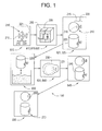
- FIG. 1 an embodiment of an exemplary investment casting process is depicted.
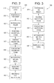
- a pictorial chart 100 and a flowchart 600 depict exemplary steps to provide an investment cast part 250, such as a turbine airfoil for example, containing a machined insert 260, which is machined subsequent to casting.
- the machined insert 260 provides material properties suited to application requirements that relate to the location of the machined insert 260 within the airfoil.
- the process begins with locating 610 a die 200, the die 200 having a cavity 205.
- the next step is positioning 615 an insert 210 relative to the die 200.
- the insert 210 has a first portion 215 and a second portion 220, each portion 215, 220 including a mechanical retention feature 216, 221 to provide alignment and retention of the insert 210, as will be described further below.
- the cavity 205 of the die 200 is larger than the first portion 215 of the insert 210, thereby allowing the first portion 215 of the insert 210 to be disposed inside the cavity 205.
- the next process step is positioning 615 the insert 210 such that the first portion 215 of the insert 210 is disposed inside the cavity 205, and the second portion 220 of the insert 210 is disposed outside the cavity 205, and captivated by the die 200.
- the position of the insert 210 shall be selected based upon the material characteristic requirements of the application for the investment cast part 250.
- introducing 620 such as injecting for example, molten filler, such as wax or plastic for example, into the cavity 205 creates a sacrificial form 225.
- the molten filler will be bonded to the first portion 215 of the insert 210.
- the mechanical retention feature 216 is configured to secure the retention and position of the insert 210 relative to the sacrificial form 225.
- the method proceeds by removing 625 the sacrificial form 225 and the insert 210 from the die 200.
- the second portion 220 of the insert 210 is disposed outside of the sacrificial form 225, while the first portion 215 is disposed and bonded inside the sacrificial form 225, as described above.
- a refractory material such as powdered silica.
- the sacrificial form 225 and the insert 210 are dipped in a slurry, which coats the sacrificial form 225, forming a skin.
- the skin is dried and the process of dipping and drying is repeated until the refractory material forms a shell 230 thick enough to provide the necessary structural support for the molten metal, as will be discussed further below.
- the material forms the shell 230 surrounding the sacrificial form 225 and the second portion 220 of the insert 210.
- the mechanical retention feature 221 of the second portion 220 is configured and disposed to secure the retention and position of the insert 210 relative to the shell 230. In this way, both mechanical retention features 216, 221 secure the position of the insert 210 relative to the investment cast part 250, allowing the position of insert 210 relative to the investment cast part 250 to remain fixed throughout the various steps of the process 100, 600.
- the shell 230 is pre-heated to drive off any remaining filler material, and to prevent possible cracks as a result of thermal shock from the high temperature of the molten metal.
- Preheating is followed by introducing 640 molten metal into the evacuated shell 230, thereby providing a metal form 240.
- the multiple layers described above are configured to provide the shell 230 with the appropriate structural strength, capable to support the weights and forces resulting from the introduction 640 of the molten metal.
- the introduction 640 of the molten metal may occur while the shell 230 and the molten metal are subject to a vacuum, in order to extract evolved gasses and reduce oxidation, thereby increasing the quality of the metal form 240.
- the first portion 215 of the insert 210 will be bonded inside the metal form 240.
- the bond between the metal form 240 and the first portion 215 may be one or both of a mechanical bond, as provided by the mechanical retention feature 216, and a metallurgical bond, resulting from diffusion between the material of the insert 210 and the material of the metal part 240.
- the next step is removing 645 the shell 230 from the metal form 240 and the second portion 220 of the insert 210.
- the shell 230 which is typically brittle, may be removed via mechanical vibration, high-pressure steam, chemical cleaners, or a combination thereof. Other removal methods may be employed while still keeping within the scope of the invention.
- the geometry of the metal form 240 which is provided by the interior of the shell 230 from which the sacrificial form 225 has been evacuated, is directly related to the geometry of the die 200 that was used to produce the sacrificial form 225.
- Factors such as thermal expansion and contraction of the filler, the shell material, and the metal will affect the final metal form 240 geometry, and are therefore considered in the configuration of the die 200.
- the insert 210 is disposed bonded within the metal form 240, there is no longer a need for the mechanical retention feature 221 of the second portion 220. Therefore, subsequent to the removing 645 of the shell 230, machining 650 the second portion 220 of the insert 210 may be done to remove the mechanical retention feature 221, providing a machined insert 260.
- the machined insert 260 shall be configured to provide the geometric tolerances and features required by the application in which the investment cast part 250 is used.
- the metal form 240 may also be machined 650 to provide the geometric tolerances and features of the investment cast metal part 250 required by the application.
- FIG. 700 A more general sense of the method depicted in Figure 2 by flowchart 600 may be represented by the method depicted in Figure 3 by flowchart 700, where like elements are numbered alike.
- positioning 621 of the insert 210 relative to the sacrificial form 225 may occur without the need to create the sacrificial form 225 within a die 200, as described above.
- the sacrificial form 225 may be provided as a machined wax or plastic form, and the insert 210 may be embedded into the sacrificial form 225 by vibratory or other suitable action.
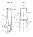
- FIG. 4 an exemplary embodiment of a gas turbine airfoil 300 is depicted. Using the process 100, 600 described above, it is contemplated that subsequent to the machining 650 of one or more of the second portion 220 of the insert 210 and the metal form 240, the turbine airfoil 300 may be produced.
- various locations of the gas turbine airfoil 300 may utilize the insert 210 to provide improved material characteristics. Between Figures 4 and 5, a tip shroud edge 305, tip shroud contact surfaces 310, an airfoil tip 315, a leading edge 320, a trailing edge 325, a platform edge 330, and angle wings 335 are depicted. It will be appreciated that each location described above as part of the airfoil 300 has a corresponding position within the cavity 205 of the die 200 configured to produce the sacrificial form 225. Further, it will be appreciated that each such position of the die 200 may be configured to receive the insert 210.
- the positioning 615 the insert 210 into the die 200 may include positioning 615 one or more inserts 210 at positions of the die 200 corresponding to the airfoil 300 locations described above.
- the first portion 215 of the machined insert 260, disposed inside the airfoil 300, is retained by one or more of a mechanical bond and a metallurgical bond.
- each location described above may utilize an insert 210 comprising materials that are suited for the conditions to which that location is exposed.
- the machined insert 260 at the airfoil tip 315 may be configured to provide one or more of improved oxidation and wear properties.
- the machined insert 260 at one or more of the trailing edge 325 and the leading edge 320 may be configured to provide improved oxidation properties.
- the machined inserts 260 at one or more of the tip shroud contact surfaces 310 and the angle wing surfaces 335 may be configured to provide improved wear properties.
- the machined inserts 260 at one or more of the platform edge 330 and the tip shroud edge 305 surfaces are contemplated to be configured to provide improved corrosion properties.
- the positioning 615 the insert 210 may include inserts 210 made of materials comprising one or more of tungsten carbide and molybdenum.
- the exact composition of the insert 210 selected for use will be related to the melting temperature of the casting metal. For example, it is contemplated to be beneficial to utilize an insert 210 that has a melting temperature greater than the melting temperature of the casting material, to avoid melting of the insert 210 in response to the introducing 640 of the molten casting material to the shell 230.
- pre-heating of the shell 230 may be performed at between 1700 to 2000 degrees Fahrenheit (927 to 1093 degrees Centigrade) prior to the introduction of molten metal alloy into the shell 230. It is contemplated that positioning 615 the insert 210 with plating comprising one or more of platinum and palladium will reduce oxidation of the inserts 210 at such elevated temperatures. Finally, the introducing 640 molten metal is contemplated to include investment casting materials that are well suited to the high temperatures present within the application of a gas turbine airfoil 300, such as alloys having one or more of nickel and cobalt.
- some embodiments of the invention may include some of the following advantages: regions of an investment casting that possess material properties optimized for application requirements; a turbine airfoil with application-specific inserts; a turbine airfoil that may be produced without coatings or thermal cooling passages; and the ability to produce a turbine airfoil having application-specific surfaces using fewer manufacturing steps.
Landscapes
- Engineering & Computer Science (AREA)
- Mechanical Engineering (AREA)
- Turbine Rotor Nozzle Sealing (AREA)
Abstract
Description
- The present disclosure relates generally to investment casting methods, and particularly to investment casting of turbine airfoils.
- A gas turbine airfoil operates in a high temperature environment. Different parts of the airfoil are subject to different stresses and temperatures. Accordingly, the application requirements of the different parts of the airfoil may conflict with one another. The turbine airfoil is often made of a single material. Selection of the single material to ensure that all parts of the airfoil will have adequate durability is a challenge that includes a substantial degree of engineering.
- The material choice tends to be a balance between all the required material characteristics of the airfoil. More specifically, differing application requirements of local areas of the airfoil typically require material properties different than those of the base material. For example, some areas such as the airfoil tip region or trailing edge, operate at higher temperatures, and will therefore benefit from the use of materials that provide increased oxidation resistance. Other areas, such as the tip shroud contact surfaces or angle wing surfaces will benefit from the use of hard materials to reduce wear. Additionally, strength, creep fatigue, and cyclic fatigue are factors that are considered as part of the material selection.
- Turbine airfoils that operate in gas turbines may be manufactured using an investment casting process. The casting material is often a high strength alloy of nickel, cobalt, or a combination thereof. The specific material choice is an engineering choice to ensure that the airfoil has the desired life given the different stresses and temperatures to which the part may be subjected in use.
- For parts of the airfoil that require different material properties than the base alloy, the general past practice has been to use coatings (such as wear and oxidation resistant coatings) or to use channels within the airfoil to provide preferential cooling. Another approach is to attach surfaces having material properties selected for specific airfoil locations onto the airfoil. Coatings increase manufacturing cost and cycle time and may have a finite durability. Preferential cooling may lead to reduced engine performance. Because of difficulties associated with welding to the airfoil base materials, until recently brazing was the only option to attach surfaces to an airfoil. Welding advances have provided some options to weld otherwise unweldable alloys. However, the use of attached surfaces increases manufacturing cost and cycle time. Accordingly, there is a need in the art for an investment casting method that overcomes these drawbacks.
- An embodiment of the invention includes a method for manufacturing an investment cast article. The method comprises positioning an insert relative to a sacrificial form, the insert comprising a first portion and a second portion, the first portion being disposed inside the sacrificial form and the second portion being disposed outside the sacrificial form. The sacrificial form and the second portion of the insert are coated with a material, forming a shell surrounding the sacrificial form and the second portion of the insert. The sacrificial form is evacuated from the shell, followed by introducing molten metal into the evacuated shell, thereby providing a metal form, and resulting in the first portion of the insert being disposed and bonded inside the metal form. The shell is removed from the metal form and the second portion of the insert, thereby resulting in the metal form with the first portion of the insert disposed and bonded therein.
- Another embodiment of the invention includes a gas turbine airfoil produced according to the method of positioning an insert relative to a sacrificial form, the insert comprising a first portion and a second portion, the first portion being disposed inside the sacrificial form and the second portion being disposed outside the sacrificial form. The sacrificial form and the second portion of the insert are coated with a material, forming a shell surrounding the sacrificial form and the second portion of the insert. The sacrificial form is evacuated from the shell, followed by introducing molten metal into the evacuated shell, thereby providing a metal form, and resulting in the first portion of the insert being disposed and bonded inside the metal form. The shell is removed from the metal form and the second portion of the insert, thereby resulting in the metal form with the first portion of the insert disposed and bonded therein. One or more of the second portion of the insert and the metal form is machined, thereby providing the turbine airfoil.
- Referring to the exemplary drawings wherein like elements are numbered alike in the accompanying Figures:
- Figure 1 depicts in pictorial form an exemplary embodiment of a method for investment casting in accordance with embodiments of the invention;
- Figure 2 depicts in flowchart form an exemplary embodiment of a method for investment casting in accordance with embodiments of the invention;
- Figure 3 depicts in flowchart form a generalized exemplary embodiment of a method for investment casting in accordance with embodiments of the invention;
- Figure 4 depicts a front perspective view of an exemplary embodiment of a turbine airfoil manufactured in accordance with embodiments of the invention; and
- Figure 5 depicts a front view of an exemplary embodiment of a turbine airfoil manufactured in accordance with embodiments of the invention.
- An embodiment of the invention provides a method to produce investment cast parts that have inserts embedded within the cast structure. By incorporating inserts, a part produced by the investment cast process may have multiple, optimized material properties, strategically located to provide desired application characteristics such as increased resistance to localized wear, oxidation, corrosion, and elevated temperature exposure.
- Another embodiment of the invention optimizes the material properties in local areas of investment cast turbine airfoils using cast preforms, or inserts. The inserts are made of specific materials having characteristics suited to the environmental exposure of the particular, localized portion of the airfoil in which the insert is placed. These preforms can be made from different materials than the base airfoil alloy. Multiple preforms of different materials are contemplated on a single airfoil. The preforms are joined to the airfoil during the investment casting process and become an integral part of the airfoil. The joining process can involve one or both of a mechanical bond and a metallurgical bond.
- Further, it is contemplated that an embodiment of the invention will provide a reduction in manufacturing steps. Following the investment casting of an airfoil, the current practice to attach a surface to the base material is to machine the airfoil location to which the surface will be applied, braze or weld the surface in place, machine the surface, and then heat treat the assembly. An embodiment of the invention provides an investment cast airfoil with a cast-in secondary surface, thereby requiring only a single machining operation.
- As a result of the investment casting process, the cast preforms become an integral part of the airfoil casting. The airfoil then has different material properties and/or structures to provide optimized characteristics tailored to the application requirements of the specific regions of the part. In this way, subsequent coatings may be eliminated, as well as the need to provide local cooling flow.
- Referring to Figure 1 in conjunction with Figure 2, an embodiment of an exemplary investment casting process is depicted. A
pictorial chart 100 and aflowchart 600 depict exemplary steps to provide aninvestment cast part 250, such as a turbine airfoil for example, containing amachined insert 260, which is machined subsequent to casting. In an embodiment, themachined insert 260 provides material properties suited to application requirements that relate to the location of themachined insert 260 within the airfoil. - The process begins with locating 610 a die 200, the die 200 having a
cavity 205. The next step is positioning 615 aninsert 210 relative to the die 200. Theinsert 210 has afirst portion 215 and asecond portion 220, eachportion mechanical retention feature insert 210, as will be described further below.. Thecavity 205 of thedie 200 is larger than thefirst portion 215 of theinsert 210, thereby allowing thefirst portion 215 of theinsert 210 to be disposed inside thecavity 205. - The next process step is positioning 615 the
insert 210 such that thefirst portion 215 of theinsert 210 is disposed inside thecavity 205, and thesecond portion 220 of theinsert 210 is disposed outside thecavity 205, and captivated by thedie 200. In an embodiment, the position of theinsert 210 shall be selected based upon the material characteristic requirements of the application for theinvestment cast part 250. After theinsert 210 has been properly positioned 615 within thedie 200, introducing 620, such as injecting for example, molten filler, such as wax or plastic for example, into thecavity 205 creates asacrificial form 225. In an embodiment, the molten filler will be bonded to thefirst portion 215 of theinsert 210. Themechanical retention feature 216 is configured to secure the retention and position of theinsert 210 relative to thesacrificial form 225. - Following the introducing 620 molten filler into the
die 200, the method proceeds by removing 625 thesacrificial form 225 and theinsert 210 from thedie 200. Thesecond portion 220 of theinsert 210 is disposed outside of thesacrificial form 225, while thefirst portion 215 is disposed and bonded inside thesacrificial form 225, as described above. - Next is coating 630 the
sacrificial form 225 and thesecond portion 220 of theinsert 210 with a refractory material, such as powdered silica. In an embodiment, thesacrificial form 225 and theinsert 210 are dipped in a slurry, which coats thesacrificial form 225, forming a skin. The skin is dried and the process of dipping and drying is repeated until the refractory material forms ashell 230 thick enough to provide the necessary structural support for the molten metal, as will be discussed further below. The material forms theshell 230 surrounding thesacrificial form 225 and thesecond portion 220 of theinsert 210. After sufficient time to allow theshell 230 to dry and solidify, heat is applied to melt the filler, thereby evacuating 635 thesacrificial form 225 from theshell 230. Uponevacuation 635 of the filler, the geometry of thesacrificial form 225 is contained by the interior of theempty shell 230. Similar to themechanical retention feature 216 of thefirst portion 215, it may be appreciated that themechanical retention feature 221 of thesecond portion 220 is configured and disposed to secure the retention and position of theinsert 210 relative to theshell 230. In this way, both mechanical retention features 216, 221 secure the position of theinsert 210 relative to the investment castpart 250, allowing the position ofinsert 210 relative to the investment castpart 250 to remain fixed throughout the various steps of theprocess - While an embodiment of the invention has been described using a refractory material of powdered silica, it will be appreciated that the scope of the invention is not so limited, and that the invention may also apply to shells made from other materials such as, but not limited to, plaster of paris, alumina-silicate, and ethyl silicate, for example. While an embodiment of the invention has been described depicting an insert with a bulb-shaped mechanical retention feature, it will be appreciated that the scope of the invention is not so limited, and that the invention may also apply to inserts using alternate means of mechanical retention, such as a thread, a knurl, a groove, and a step, for example.
- In an embodiment, the
shell 230 is pre-heated to drive off any remaining filler material, and to prevent possible cracks as a result of thermal shock from the high temperature of the molten metal. Preheating is followed by introducing 640 molten metal into the evacuatedshell 230, thereby providing ametal form 240. It will be appreciated that the multiple layers described above are configured to provide theshell 230 with the appropriate structural strength, capable to support the weights and forces resulting from theintroduction 640 of the molten metal. Theintroduction 640 of the molten metal may occur while theshell 230 and the molten metal are subject to a vacuum, in order to extract evolved gasses and reduce oxidation, thereby increasing the quality of themetal form 240. Subsequent to introducing 640 molten metal, thefirst portion 215 of theinsert 210 will be bonded inside themetal form 240. The bond between themetal form 240 and thefirst portion 215 may be one or both of a mechanical bond, as provided by themechanical retention feature 216, and a metallurgical bond, resulting from diffusion between the material of theinsert 210 and the material of themetal part 240. - After sufficient time to allow the
metal form 240 to cool, the next step is removing 645 theshell 230 from themetal form 240 and thesecond portion 220 of theinsert 210. In an embodiment, theshell 230, which is typically brittle, may be removed via mechanical vibration, high-pressure steam, chemical cleaners, or a combination thereof. Other removal methods may be employed while still keeping within the scope of the invention. - It will be appreciated that the geometry of the
metal form 240, which is provided by the interior of theshell 230 from which thesacrificial form 225 has been evacuated, is directly related to the geometry of the die 200 that was used to produce thesacrificial form 225. Factors such as thermal expansion and contraction of the filler, the shell material, and the metal will affect thefinal metal form 240 geometry, and are therefore considered in the configuration of thedie 200. - Because the
insert 210 is disposed bonded within themetal form 240, there is no longer a need for themechanical retention feature 221 of thesecond portion 220. Therefore, subsequent to the removing 645 of theshell 230, machining 650 thesecond portion 220 of theinsert 210 may be done to remove themechanical retention feature 221, providing amachined insert 260. In an embodiment, the machinedinsert 260 shall be configured to provide the geometric tolerances and features required by the application in which the investment castpart 250 is used. Themetal form 240 may also be machined 650 to provide the geometric tolerances and features of the investment castmetal part 250 required by the application. - A more general sense of the method depicted in Figure 2 by
flowchart 600 may be represented by the method depicted in Figure 3 byflowchart 700, where like elements are numbered alike. In theflowchart 700, positioning 621 of theinsert 210 relative to thesacrificial form 225 may occur without the need to create thesacrificial form 225 within adie 200, as described above. For example, thesacrificial form 225 may be provided as a machined wax or plastic form, and theinsert 210 may be embedded into thesacrificial form 225 by vibratory or other suitable action. - Referring now to Figures 4 and 5, an exemplary embodiment of a
gas turbine airfoil 300 is depicted. Using theprocess machining 650 of one or more of thesecond portion 220 of theinsert 210 and themetal form 240, theturbine airfoil 300 may be produced. - In an embodiment, various locations of the
gas turbine airfoil 300 may utilize theinsert 210 to provide improved material characteristics. Between Figures 4 and 5, atip shroud edge 305, tip shroud contact surfaces 310, anairfoil tip 315, aleading edge 320, a trailingedge 325, aplatform edge 330, andangle wings 335 are depicted. It will be appreciated that each location described above as part of theairfoil 300 has a corresponding position within thecavity 205 of the die 200 configured to produce thesacrificial form 225. Further, it will be appreciated that each such position of thedie 200 may be configured to receive theinsert 210. Accordingly, the positioning 615 theinsert 210 into thedie 200 may include positioning 615 one ormore inserts 210 at positions of the die 200 corresponding to theairfoil 300 locations described above. In an embodiment, thefirst portion 215 of the machinedinsert 260, disposed inside theairfoil 300, is retained by one or more of a mechanical bond and a metallurgical bond. - In an embodiment of the invention, it is contemplated that each location described above may utilize an
insert 210 comprising materials that are suited for the conditions to which that location is exposed. It is contemplated that themachined insert 260 at theairfoil tip 315 may be configured to provide one or more of improved oxidation and wear properties. It is further contemplated that themachined insert 260 at one or more of the trailingedge 325 and theleading edge 320 may be configured to provide improved oxidation properties. The machined inserts 260 at one or more of the tip shroud contact surfaces 310 and the angle wing surfaces 335 may be configured to provide improved wear properties. The machined inserts 260 at one or more of theplatform edge 330 and thetip shroud edge 305 surfaces are contemplated to be configured to provide improved corrosion properties. - Materials that may provide characteristics pertinent to the localized application needs of the
gas turbine airfoil 300, such as high temperature, oxidation, wear, and corrosion resistance include, but are not limited to, tungsten carbide and molybdenum. Accordingly, in an embodiment, the positioning 615 theinsert 210 may includeinserts 210 made of materials comprising one or more of tungsten carbide and molybdenum. The exact composition of theinsert 210 selected for use will be related to the melting temperature of the casting metal. For example, it is contemplated to be beneficial to utilize aninsert 210 that has a melting temperature greater than the melting temperature of the casting material, to avoid melting of theinsert 210 in response to the introducing 640 of the molten casting material to theshell 230. In an embodiment, pre-heating of theshell 230 may be performed at between 1700 to 2000 degrees Fahrenheit (927 to 1093 degrees Centigrade) prior to the introduction of molten metal alloy into theshell 230. It is contemplated that positioning 615 theinsert 210 with plating comprising one or more of platinum and palladium will reduce oxidation of theinserts 210 at such elevated temperatures. Finally, the introducing 640 molten metal is contemplated to include investment casting materials that are well suited to the high temperatures present within the application of agas turbine airfoil 300, such as alloys having one or more of nickel and cobalt. - As disclosed, some embodiments of the invention may include some of the following advantages: regions of an investment casting that possess material properties optimized for application requirements; a turbine airfoil with application-specific inserts; a turbine airfoil that may be produced without coatings or thermal cooling passages; and the ability to produce a turbine airfoil having application-specific surfaces using fewer manufacturing steps.
- While the invention has been described with reference to exemplary embodiments, it will be understood by those skilled in the art that various changes may be made and equivalents may be substituted for elements thereof without departing from the scope of the invention. In addition, many modifications may be made to adapt a particular situation or material to the teachings of the invention without departing from the essential scope thereof. Therefore, it is intended that the invention not be limited to the particular embodiment disclosed as the best or only mode contemplated for carrying out this invention, but that the invention will include all embodiments falling within the scope of the appended claims. Also, in the drawings and the description, there have been disclosed exemplary embodiments of the invention and, although specific terms may have been employed, they are unless otherwise stated used in a generic and descriptive sense only and not for purposes of limitation, the scope of the invention therefore not being so limited. Moreover, the use of the terms first, second, etc. do not denote any order or importance, but rather the terms first, second, etc. are used to distinguish one element from another. Furthermore, the use of the terms a, an, etc. do not denote a limitation of quantity, but rather denote the presence of at least one of the referenced item.
Claims (10)
- A method for manufacturing an investment cast article (250), the method comprising:positioning (621) an insert (210) relative to a sacrificial form (225), the insert (210) comprising a first portion (215) and a second portion (220), the first portion (215) being disposed inside the sacrificial form (225) and the second portion (220) being disposed outside the sacrificial form (225);coating (630) the sacrificial form (225) and the second portion (220) of the insert (210) with a material, the material forming a shell (230) surrounding the sacrificial form (225) and the second portion (220) of the insert (210);evacuating (635) the sacrificial form (225) from the shell (230);introducing (640) molten metal into the evacuated shell (230), thereby providing a metal form (240), and resulting in the first portion (215) of the insert (210) being disposed and bonded inside the metal form (240); andremoving (645) the shell (230) from the metal form (240) and the second portion (220) of the insert (210), thereby resulting in the metal form (240) with the first portion (215) of the insert (210) disposed and bonded therein.
- The method of Claim 1, wherein:the introducing (640) molten metal occurs while the shell (230) and the molten metal are subject to a vacuum.
- The method of Claim 1 or Claim 2, wherein the positioning (621) comprises:positioning (621) the insert comprising mechanical retention features (216).
- The method of Claim 1, wherein:the manufacturing comprises manufacturing an investment cast gas turbine airfoil (300);the positioning further comprises:positioning (615) the insert (210) relative to a die (200) having a cavity (205) larger than the first portion (215) of the insert (210), such that the first portion (215) of the insert (210) is disposed inside the cavity (205), and the second portion (220) of the insert (210) is disposed outside the cavity (205) and captivated by the die (200);introducing (620) molten filler into the cavity (205) to create the sacrificial form (225), resulting in the filler being bonded to the first portion (215) of the insert (210);removing (625) the sacrificial form (225) and the insert (210) from the die (200), the second portion (220) of the insert (210) disposed outside the sacrificial form (225), thereby providing the sacrificial form (225) and the insert (210);the die cavity (205) has a plurality of positions that correspond to an airfoil tip (315), an airfoil leading edge (320), an airfoil trailing edge (325), airfoil tip shroud contact surfaces (310), airfoil angle wings (335), an airfoil platform edge (330), and an airfoil tip shroud edge (305); andthe positioning (615) comprises positioning (615) one or more inserts (210) at the positions of the die cavity (205) corresponding to one or more of the airfoil tip (315), the airfoil leading edge (320), the airfoil trailing edge (325), the airfoil tip shroud contact surfaces (310), the airfoil angle wings (335), the airfoil platform edge (330), and the airfoil tip (315) shroud edge (305).
- A gas turbine airfoil (300) produced according to the method of:positioning (621) an insert (210) relative to a sacrificial form (225), the insert (210) comprising a first portion (215) and a second portion (220), the first portion (215) being disposed inside the sacrificial form (225) and the second portion (220) being disposed outside the sacrificial form (225);coating (630) the sacrificial form (225) and the second portion (220) of the insert (210) with a material, the material forming a shell (230) surrounding the sacrificial form (225) and the second portion (220) of the insert (210);evacuating (635) the sacrificial form (225) from the shell (230);introducing (640) molten metal into the evacuated shell (230), thereby providing a metal form (240), and resulting in the first portion (215) of the insert (210) being disposed and bonded inside the metal form (240); andremoving (645) the shell (230) from the metal form (240) and the second portion (220) of the insert (210), thereby resulting in the metal form (240) with the first portion (215) of the insert (210) disposed and bonded therein;machining (650) one or more of the second portion (220) of the insert (210) and the metal form (240), thereby providing the turbine airfoil (300).
- The gas turbine airfoil (300) of Claim 5, wherein:the insert (210) comprises mechanical retention features (216).
- The gas turbine airfoil (300) of Claim 5, wherein:the first portion (215) of the machined insert (260) is retained by one or more of a mechanical bond and a metallurgical bond.
- The gas turbine airfoil (300) of Claim 5, wherein:the airfoil (300) is made from an alloy of nickel, cobalt, or a combination thereof; andthe insert (210) is made from a material to provide characteristics pertinent to localized application needs of the gas turbine airfoil (300) including at least one of temperature, oxidation, wear, and corrosion resistance.
- The gas turbine airfoil (300) of Claim 5, comprising:an airfoil tip (315), an airfoil leading edge (300), an airfoil trailing edge (325), airfoil tip (315) shroud contact surfaces (310), airfoil angle wings (335), an airfoil platform edge (330), and an airfoil tip shroud edge (305);one or more machined inserts (260) at one or more of the following locations of the airfoil: the airfoil tip (315); the airfoil leading edge (320); the airfoil trailing edge (325); the airfoil tip shroud contact surfaces (310); the airfoil angle wings (335); the airfoil platform edge (330); and the airfoil tip shroud edge (305).
- The gas turbine airfoil (300) of Claim 5 wherein:the melting temperature of the insert (210) is greater than the melting temperature of the metal form (240).
Applications Claiming Priority (1)
| Application Number | Priority Date | Filing Date | Title |
|---|---|---|---|
| US11/406,176 US20070240845A1 (en) | 2006-04-18 | 2006-04-18 | Investment cast article and method of production thereof |
Publications (1)
| Publication Number | Publication Date |
|---|---|
| EP1867409A1 true EP1867409A1 (en) | 2007-12-19 |
Family
ID=38432934
Family Applications (1)
| Application Number | Title | Priority Date | Filing Date |
|---|---|---|---|
| EP07106279A Withdrawn EP1867409A1 (en) | 2006-04-18 | 2007-04-17 | Investment cast article and method of production thereof |
Country Status (2)
| Country | Link |
|---|---|
| US (1) | US20070240845A1 (en) |
| EP (1) | EP1867409A1 (en) |
Families Citing this family (4)
| Publication number | Priority date | Publication date | Assignee | Title |
|---|---|---|---|---|
| FR2982781B1 (en) * | 2011-11-21 | 2016-06-10 | Snecma | PROCESS FOR THE FOUNDED PRODUCTION OF A HETEROGENEOUS PIECE |
| FR2991612B1 (en) | 2012-06-11 | 2017-12-08 | Snecma | PROCESS FOR THE FOUNDED PRODUCTION OF A PIECE COMPRISING AN EFFICIENT PORTION |
| WO2014093826A2 (en) | 2012-12-14 | 2014-06-19 | United Technologies Corporation | Multi-shot casting |
| EP3513889B1 (en) | 2012-12-14 | 2021-04-14 | Raytheon Technologies Corporation | Alloy and hybrid turbine blade for improved engine performance or architecture |
Citations (5)
| Publication number | Priority date | Publication date | Assignee | Title |
|---|---|---|---|---|
| GB781492A (en) * | 1954-12-10 | 1957-08-21 | Chrysler Corp | Improvements in or relating to an air cooled turbine blade |
| GB872705A (en) * | 1959-01-22 | 1961-07-12 | Gen Motors Corp | Improvements in cast turbine blades and the manufacture thereof |
| GB2078596A (en) * | 1980-06-19 | 1982-01-13 | Rolls Royce | Method of Making a Blade |
| FR2698297A1 (en) * | 1992-11-23 | 1994-05-27 | Peugeot | Expanded polymer model moulding procedure - filling mould with polymer balls after fitting insert and expanding these with aid of steam to fill mould |
| WO2006014949A2 (en) * | 2004-07-30 | 2006-02-09 | Dana Corporation | Article casting method |
Family Cites Families (10)
| Publication number | Priority date | Publication date | Assignee | Title |
|---|---|---|---|---|
| US3215511A (en) * | 1962-03-30 | 1965-11-02 | Union Carbide Corp | Gas turbine nozzle vane and like articles |
| CH640441A5 (en) * | 1979-09-10 | 1984-01-13 | Hans Schneider | METHOD FOR PRODUCING CASTING PIECES BY PRECISION CASTING. |
| US5241737A (en) * | 1991-03-21 | 1993-09-07 | Howmet Corporation | Method of making a composite casting |
| US5623985A (en) * | 1996-03-13 | 1997-04-29 | Pcc Airfoils, Inc. | Apparatus and method for molding an article |
| US6349759B1 (en) * | 1999-04-05 | 2002-02-26 | Pcc Airfoils, Inc. | Apparatus and method for casting a metal article |
| US6332926B1 (en) * | 1999-08-11 | 2001-12-25 | General Electric Company | Apparatus and method for selectively coating internal and external surfaces of an airfoil |
| US6609894B2 (en) * | 2001-06-26 | 2003-08-26 | General Electric Company | Airfoils with improved oxidation resistance and manufacture and repair thereof |
| US6575702B2 (en) * | 2001-10-22 | 2003-06-10 | General Electric Company | Airfoils with improved strength and manufacture and repair thereof |
| DE10236339B3 (en) * | 2002-08-08 | 2004-02-19 | Doncasters Precision Castings-Bochum Gmbh | Method for manufacturing turbine blades with cooling ducts involves making ceramic core with positioning pins embedded in free end to protrude into surrounding moulding shell for removal during mechanical finishing of hardened blades |
| US7134475B2 (en) * | 2004-10-29 | 2006-11-14 | United Technologies Corporation | Investment casting cores and methods |
-
2006
- 2006-04-18 US US11/406,176 patent/US20070240845A1/en not_active Abandoned
-
2007
- 2007-04-17 EP EP07106279A patent/EP1867409A1/en not_active Withdrawn
Patent Citations (5)
| Publication number | Priority date | Publication date | Assignee | Title |
|---|---|---|---|---|
| GB781492A (en) * | 1954-12-10 | 1957-08-21 | Chrysler Corp | Improvements in or relating to an air cooled turbine blade |
| GB872705A (en) * | 1959-01-22 | 1961-07-12 | Gen Motors Corp | Improvements in cast turbine blades and the manufacture thereof |
| GB2078596A (en) * | 1980-06-19 | 1982-01-13 | Rolls Royce | Method of Making a Blade |
| FR2698297A1 (en) * | 1992-11-23 | 1994-05-27 | Peugeot | Expanded polymer model moulding procedure - filling mould with polymer balls after fitting insert and expanding these with aid of steam to fill mould |
| WO2006014949A2 (en) * | 2004-07-30 | 2006-02-09 | Dana Corporation | Article casting method |
Also Published As
| Publication number | Publication date |
|---|---|
| US20070240845A1 (en) | 2007-10-18 |
Similar Documents
| Publication | Publication Date | Title |
|---|---|---|
| US6648596B1 (en) | Turbine blade or turbine vane made of a ceramic foam joined to a metallic nonfoam, and preparation thereof | |
| US7966707B2 (en) | Method for repairing superalloy components using inserts | |
| EP1775054B1 (en) | Weld closure of through-holes in a nickel-base superalloy hollow airfoil | |
| CN100420537C (en) | Methods of Welding Repaired Parts | |
| US20050025613A1 (en) | Integral turbine composed of a cast single crystal blade ring diffusion bonded to a high strength disk | |
| EP1055480A2 (en) | Repair of a recess in an article surface | |
| CN101108453A (en) | Process for repairing turbine engine components | |
| US20060248718A1 (en) | Superalloy repair methods and inserts | |
| US20100200189A1 (en) | Method of fabricating turbine airfoils and tip structures therefor | |
| US5743322A (en) | Method for forming an article extension by casting using a ceramic mold | |
| US20100064515A1 (en) | Method for repairing and/or replacing individual elements of a gas turbine component | |
| US5673745A (en) | Method for forming an article extension by melting of an alloy preform in a ceramic mold | |
| EP1867409A1 (en) | Investment cast article and method of production thereof | |
| US9156086B2 (en) | Multi-component assembly casting | |
| EP0815990B1 (en) | Solidification of an article extension from a melt using an integral mandrel and ceramic mold | |
| US5904201A (en) | Solidification of an article extension from a melt using a ceramic mold | |
| CN107150185A (en) | Brazing composition, method for welding and brazed products | |
| EP3725457B1 (en) | Turbine casing component and repair method therefor | |
| EP1728971A1 (en) | Integral turbine composed of a cast single crystal blade ring diffusion bonded to a high strength disk | |
| US5673744A (en) | Method for forming an article extension by melting of a mandrel in a ceramic mold | |
| EP3927943B1 (en) | Tip repair of a turbine component using a composite tip boron base pre-sintered preform | |
| US6582812B1 (en) | Article made of a ceramic foam joined to a metallic nonfoam, and its preparation | |
| CA2696274A1 (en) | Method for fabricating turbine airfoils and tip structures therefor |
Legal Events
| Date | Code | Title | Description |
|---|---|---|---|
| PUAI | Public reference made under article 153(3) epc to a published international application that has entered the european phase |
Free format text: ORIGINAL CODE: 0009012 |
|
| AK | Designated contracting states |
Kind code of ref document: A1 Designated state(s): AT BE BG CH CY CZ DE DK EE ES FI FR GB GR HU IE IS IT LI LT LU LV MC MT NL PL PT RO SE SI SK TR |
|
| AX | Request for extension of the european patent |
Extension state: AL BA HR MK YU |
|
| 17P | Request for examination filed |
Effective date: 20080619 |
|
| AKX | Designation fees paid |
Designated state(s): DE FR GB |
|
| 17Q | First examination report despatched |
Effective date: 20080725 |
|
| STAA | Information on the status of an ep patent application or granted ep patent |
Free format text: STATUS: THE APPLICATION IS DEEMED TO BE WITHDRAWN |
|
| 18D | Application deemed to be withdrawn |
Effective date: 20101102 |