EP1867406A1 - Closing method and closing machine - Google Patents
Closing method and closing machine Download PDFInfo
- Publication number
- EP1867406A1 EP1867406A1 EP06731219A EP06731219A EP1867406A1 EP 1867406 A1 EP1867406 A1 EP 1867406A1 EP 06731219 A EP06731219 A EP 06731219A EP 06731219 A EP06731219 A EP 06731219A EP 1867406 A1 EP1867406 A1 EP 1867406A1
- Authority
- EP
- European Patent Office
- Prior art keywords
- work piece
- die
- closing
- support shaft
- transmission mechanism
- Prior art date
- Legal status (The legal status is an assumption and is not a legal conclusion. Google has not performed a legal analysis and makes no representation as to the accuracy of the status listed.)
- Granted
Links
Images



Classifications
-
- B—PERFORMING OPERATIONS; TRANSPORTING
- B21—MECHANICAL METAL-WORKING WITHOUT ESSENTIALLY REMOVING MATERIAL; PUNCHING METAL
- B21D—WORKING OR PROCESSING OF SHEET METAL OR METAL TUBES, RODS OR PROFILES WITHOUT ESSENTIALLY REMOVING MATERIAL; PUNCHING METAL
- B21D41/00—Application of procedures in order to alter the diameter of tube ends
- B21D41/04—Reducing; Closing
- B21D41/045—Closing
-
- B—PERFORMING OPERATIONS; TRANSPORTING
- B21—MECHANICAL METAL-WORKING WITHOUT ESSENTIALLY REMOVING MATERIAL; PUNCHING METAL
- B21D—WORKING OR PROCESSING OF SHEET METAL OR METAL TUBES, RODS OR PROFILES WITHOUT ESSENTIALLY REMOVING MATERIAL; PUNCHING METAL
- B21D22/00—Shaping without cutting, by stamping, spinning, or deep-drawing
- B21D22/14—Spinning
Definitions
- This invention relates to an improvement in a closing method and a closing machine for closing an open end of a metal pipe material.
- a closing method a work piece constituted by a metal pipe material is rotated and a die is pressed against the work piece while the work piece is heated.
- the work piece undergoes plastic deformation as it gradually approaches the die.
- a closing machine used in the closing operation comprises an outer diameter chuck that grips an outer peripheral surface of the work piece, and a chuck spindle that drives the outer diameter chuck to rotate together with the work piece.
- the work piece is closed by pressing the rotating die against the work piece at an offset to the rotating work piece.
- JP2002-153930A The closing method and closing machine described above are disclosed in JP2002-153930A .
- a die is pressed against a work piece so as to be brought into sliding contact therewith, and as a result, the die rotates in accordance with the work piece, which rotates at a higher speed than the die.
- This invention provides a closing method for closing an open end of a work piece by pressing a rotating die against the work piece rotating about an axial center, characterized in that the die, which is disposed coaxially with the work piece, is supported rotatably by a die support shaft, a torque of a motor is transmitted to the die support shaft via a power transmission mechanism, a torque input into the power transmission mechanism from the die support shaft is blocked via a one-way clutch, and during closing operation, the die is pressed against the work piece so as to contact the work piece slidingly such that the die rotates in accordance with the work piece, which rotates at a higher speed than the die.
- This invention also provides a closing machine for closing an open end of a work piece by pressing a rotating die against the work piece rotating about an axial center, characterized by a die support shaft that supports the die, which is disposed coaxially with the work piece, rotatably a power transmission mechanism which transmits a torque of a motor to the die support shaft and a one-way clutch which blocks a torque that is input into the power transmission mechanism from the die support shaft.
- a closing machine for closing an open end of a work piece by pressing a rotating die against the work piece rotating about an axial center, characterized by a die support shaft that supports the die, which is disposed coaxially with the work piece, rotatably a power transmission mechanism which transmits a torque of a motor to the die support shaft and a one-way clutch which blocks a torque that is input into the power transmission mechanism from the die support shaft.
- the one-way clutch blocks torque transmission from the die support shaft to the power transmission mechanism, and therefore the die support shaft rotates freely relative to the power transmission mechanism, leading to a reduction in the inertial mass of a drive system that rotates together with the die.
- the rotation of the die catches up with the rotation of the work piece quickly, enabling a reduction in the tact time and an improvement in productivity.
- FIGs. 1 to 3 show the overall constitution of a closing machine 1.
- three axes namely X, Y, and Z, are set orthogonal to each other. It is assumed that the X axis extends in a substantially horizontal lateral direction, the Y axis extends in a substantially horizontal front-rear direction, and the Z axis extends in a substantially vertical direction.
- the overall constitution of the closing machine 1 will now be described.
- Two chuck spindles 20 which drive a work piece 9 to rotate about its axial center, and a single die driving device 40 which drives a die 4, are provided in a central portion of the closing machine 1.
- the chuck spindles 20 perform a reciprocating motion in the X axis direction relative to a pedestal 3 via a chuck spindle moving device 30, to be described later, thereby moving alternately to the central portion of the closing machine 1 so as to bring the work piece 9 face to face with the die 4.
- the closing machine 1 performs a closing operation to close an open end of the work piece 9 by heating the work piece 9, which is constituted by a metal pipe material, using a high-frequency heating device 2, and pressing the die 4 against the rotating work piece 9 such that the work piece 9 undergoes plastic deformation.
- a thrust stopper moving device 60 which is positioned in front of the chuck spindle 20 for closing the work piece 9 so as to support an end portion of the work piece 9, and a core moving device 50, which moves a core 5 inside the work piece 9, are provided in the central portion of the closing machine 1.
- a pair of conveyors 18 and a work piece introducing device 10 are provided respectively on the left and right rear portions of the working machine 1.
- the work piece 9 is conveyed forward in the Y axis direction by each of the conveyors 18 and then conveyed forward in the Y axis direction by each of the work piece introducing devices 10, which are capable of movement in the Y axis direction.
- the work piece 9 is introduced into and gripped by the respective left and right chuck spindles 20.
- While one of the chuck spindles 20 is positioned in the central portion of the working machine 1 during a closing operation, the other chuck spindle 20 is positioned on either the left or right end portion of the closing machine 1 so as to receive the work piece 9 conveyed by the respective work piece introducing devices 10.
- a discharge device 17 for discharging the work piece 9 following the closing operation is provided at the front portion of the closing machine 1.
- the discharge device 17 causes a hand 13 gripping the work piece 9 to reciprocate in the X axis direction relative to the pedestal 3 such that the work piece 9, which is pushed out from the left and right chuck spindles 20, is conveyed to a conveyor 19 disposed on the right-hand front portion of the closing machine 1.
- the cooling device 70 is provided on the front right side of the closing machine 1.
- FIGs. 4A to 4G show a series of processes performed by the closing machine 1 to close the work piece 9. Each process of this closing method will now be described in sequence.
- an inner diameter chuck 8 of the work piece introducing device 10 is inserted into the work piece 9 such that the inner diameter chuck 8 grips the inner peripheral surface of the work piece 9.
- the work piece introducing device 10 causes the inner diameter chuck 8 to advance in the Y axis direction such that the work piece 9 is inserted into an outer diameter chuck 7 of the chuck spindle 20.
- the outer diameter chuck 7 grips the outer peripheral surface of the work piece 9.
- the work piece introducing device 10 causes the inner diameter chuck 8 to retreat in the Y axis direction such that the inner diameter chuck 8 is extracted from the work piece 9.
- the chuck spindle moving device 30 moves the chuck spindle 20 in the X axis direction until the work piece 9 is stopped in an operation position facing the die 4.
- the thrust stopper moving device 60 moves a thrust stopper 6 to a thrust operation reference position supporting a base end portion 9b of the work piece 9.
- the core moving device 50 introduces the core 5 into the inside of the work piece 9.
- the chuck spindle 20 drives the work piece 9 and the core 5 to rotate. Meanwhile, the die 4 is pressed against the heated work piece 9 by the die driving device 40. Thus, a tip end portion 9a of the work piece 9 is steadily reduced in diameter between the die 4 and the core 5 such that finally, the tip end portion 9a of the work piece 9 closes to form a bottom portion 9c.
- the die driving device 40 moves the die 4 rearward in the Y axis direction away from the work piece 9. Meanwhile, the thrust stopper moving device 60 moves the thrust stopper 6 forward in the Y axis direction away from the thrust operation reference position, and the core moving device 50 removes the core 5 from the inside of the work piece 9.
- the chuck spindle moving device 30 moves the chuck spindle 20 in the X axis direction such that the work piece 9 faces the inner diameter chuck 8, as shown in FIG. 4A.
- the work piece introducing device 10 causes the inner diameter chuck 8 to advance in the Y axis direction such that the base end portion 9b of the unclosed work piece 9 abuts against the bottom portion 9c of the closed work piece 9, and thus the closed work piece 9 is pushed out of the outer diameter chuck 7.
- the work piece introducing device 10 causes the inner diameter chuck 8 to advance in the Y axis direction, as shown in FIG. 4H, such that the inner diameter chuck 8 abuts against the bottom portion 9c of the closed work piece 9, and thus the closed work piece 9 is pushed out of the outer diameter chuck 7.
- the die driving device 40 comprises a die support shaft 41, the die 4 being attached to a front end portion thereof, a die support case 42 which supports the die support shaft 41 rotatably via a bearing not shown in the figure, two guide rails 44 which support a sliding table 43 carrying the die support case 42 movably in the Y axis direction, and a hydraulic cylinder 45 which drives the sliding table 43 in the Y axis direction.
- the hydraulic cylinder 45 moves the die support case 42 forward in the Y axis direction during a closing operation in accordance with the output of a controller, not shown in the figure, such that the die 4 is pressed against the work piece 9.
- the die driving device 40 comprises the die support shaft 41 which supports the die 4 rotatably, a power transmission mechanism 401 which transmits the rotation of a motor 46 to the die support shaft 41, and a one-way clutch 410 which inputs torque from the power transmission mechanism 401 to the die support shaft 41 while blocking torque input from the die support shaft 41 to the power transmission mechanism 401.
- the one-way clutch 410 has a rotation transmission mechanism which transmits torque from the motor 46 to the die support shaft 41 but blocks torque transmission from the die support shaft 41 to the motor 46.
- the power transmission mechanism 401 comprises a pulley 403 connected to an output shaft 402 of the motor 46, a pulley 404 connected to the die support shaft 41 side, and a belt 405 wrapped around the two pulleys 403, 404.
- the one-way clutch 410 is interposed between the die support shaft 41 and an output shaft 406 of the power transmission mechanism 401, and serves to block torque transmission from the die support shaft 41 to the output shaft 406 of the power transmission mechanism 401.
- One end of the output shaft 406 of the power transmission mechanism 401 constitutes the one-way clutch 410, and the pulley 404 is connected to the other end.
- the motor 46 drives the die 4 to rotate via the one-way clutch 410 and drives the work piece 9 to rotate via the chuck spindle 20.
- the rotation speed of the die 4 is set to be slightly lower than the rotation speed of the work piece 9.
- the die 4 is pressed against the work piece 9 so as to contact the work piece 9 slidingly.
- the die 4 catches up with the work piece 9, which rotates at a higher speed than the die 4, such that the die 4 and work piece 9 rotate at a substantially identical speed.
- the one-way clutch 410 blocks torque transmission from the die support shaft 41 to the output shaft 406 of the power transmission mechanism 401.
- the output shaft 406 of the power transmission mechanism 401 is cut off from the die support shaft 41 via the one-way clutch 410, and therefore the die support shaft 41 rotates freely relative to the output shaft 406 of the power transmission mechanism 401, leading to a reduction in the inertial mass of the drive system that rotates together with the die 4.
- the rotation of the die 4 catches up with the rotation of the work piece 9 quickly, enabling a reduction in the tact time required to close a single work piece 9 and an improvement in productivity.
- the die support shaft 41 rotates together with the pulley 403 of the power transmission mechanism 401, causing the belt 45 to revolve, and therefore, even if the one-way clutch 410 blocks torque transmission from the die support shaft 41 to the motor 46 while the die 4 accelerates to catch up with the work piece 9, the rotation of the die 4 catches up with the rotation of the work piece 9 slowly due to the large inertial mass of the drive system that rotates together with the die 4, and as a result, the tact time increases.
- the power transmission mechanism 401 for transmitting the rotation of the motor 46 to the die support shaft 41 is not limited to a constitution comprising the pulleys 403, 404 and the belt 405, and may employ gears or another mechanism, for example.
- the closing method and closing machine of this invention are not limited to a closing operation such as that described above, for closing an open end of a work piece, and may be used in a spinning operation to reduce the diameter of a work piece by pressing a die against the rotating work piece.
Landscapes
- Engineering & Computer Science (AREA)
- Mechanical Engineering (AREA)
- Forging (AREA)
- Shaping Metal By Deep-Drawing, Or The Like (AREA)
Abstract
Description
- This invention relates to an improvement in a closing method and a closing machine for closing an open end of a metal pipe material.
- In a closing method, a work piece constituted by a metal pipe material is rotated and a die is pressed against the work piece while the work piece is heated. Thus, the work piece undergoes plastic deformation as it gradually approaches the die.
- A closing machine used in the closing operation comprises an outer diameter chuck that grips an outer peripheral surface of the work piece, and a chuck spindle that drives the outer diameter chuck to rotate together with the work piece. The work piece is closed by pressing the rotating die against the work piece at an offset to the rotating work piece.
- The closing method and closing machine described above are disclosed in
JP2002-153930A - During a closing operation in a conventional closing machine, a die is pressed against a work piece so as to be brought into sliding contact therewith, and as a result, the die rotates in accordance with the work piece, which rotates at a higher speed than the die.
- However, during a closing operation in this conventional closing machine, when the die accelerates to catch up with the work piece, the rotation of the die cannot catch up with the rotation of the work piece quickly due to the large inertial mass of a drive system that rotates together with the die, and as a result, the tact time increases.
- It is therefore an object of this invention to provide a closing method and a closing machine with which a rotating die can catch up with a rotating work piece quickly.
- This invention provides a closing method for closing an open end of a work piece by pressing a rotating die against the work piece rotating about an axial center, characterized in that the die, which is disposed coaxially with the work piece, is supported rotatably by a die support shaft, a torque of a motor is transmitted to the die support shaft via a power transmission mechanism, a torque input into the power transmission mechanism from the die support shaft is blocked via a one-way clutch, and during closing operation, the die is pressed against the work piece so as to contact the work piece slidingly such that the die rotates in accordance with the work piece, which rotates at a higher speed than the die.
- This invention also provides a closing machine for closing an open end of a work piece by pressing a rotating die against the work piece rotating about an axial center, characterized by a die support shaft that supports the die, which is disposed coaxially with the work piece, rotatably a power transmission mechanism which transmits a torque of a motor to the die support shaft and a one-way clutch which blocks a torque that is input into the power transmission mechanism from the die support shaft. During a closing operation, the die is pressed against the work piece so as to contact the work piece slidingly such that the die rotates in accordance with the work piece, which rotates at a higher speed than the die.
- According to this invention, while the die accelerates to catch up with the work piece during a closing operation, the one-way clutch blocks torque transmission from the die support shaft to the power transmission mechanism, and therefore the die support shaft rotates freely relative to the power transmission mechanism, leading to a reduction in the inertial mass of a drive system that rotates together with the die. As a result, the rotation of the die catches up with the rotation of the work piece quickly, enabling a reduction in the tact time and an improvement in productivity.
-
- FIG. 1 is a side view of a closing machine, illustrating an embodiment of this invention.
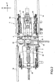
- FIG. 2 is a plan view of the closing machine.
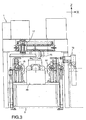
- FIG. 3 is a front view of the closing machine.
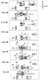
- FIGs. 4A - 4H are views showing closing processes.
- FIG. 5 is a side view of a die driving device.
- FIG.6 is a plan view of the die driving device.
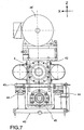
- FIG. 7 is a front view of the die driving device.
- This invention will now be described in further detail with reference to the attached drawings.
- FIGs. 1 to 3 show the overall constitution of a
closing machine 1. In FIGs. 1 to 3, three axes, namely X, Y, and Z, are set orthogonal to each other. It is assumed that the X axis extends in a substantially horizontal lateral direction, the Y axis extends in a substantially horizontal front-rear direction, and the Z axis extends in a substantially vertical direction. The overall constitution of theclosing machine 1 will now be described. - Two chuck spindles 20 which drive a
work piece 9 to rotate about its axial center, and a singledie driving device 40 which drives adie 4, are provided in a central portion of theclosing machine 1. Thechuck spindles 20 perform a reciprocating motion in the X axis direction relative to apedestal 3 via a chuckspindle moving device 30, to be described later, thereby moving alternately to the central portion of theclosing machine 1 so as to bring thework piece 9 face to face with thedie 4. - The
closing machine 1 performs a closing operation to close an open end of thework piece 9 by heating thework piece 9, which is constituted by a metal pipe material, using a high-frequency heating device 2, and pressing thedie 4 against therotating work piece 9 such that thework piece 9 undergoes plastic deformation. - A thrust
stopper moving device 60, which is positioned in front of thechuck spindle 20 for closing thework piece 9 so as to support an end portion of thework piece 9, and acore moving device 50, which moves acore 5 inside thework piece 9, are provided in the central portion of theclosing machine 1. - A pair of
conveyors 18 and a workpiece introducing device 10 are provided respectively on the left and right rear portions of theworking machine 1. Thework piece 9 is conveyed forward in the Y axis direction by each of theconveyors 18 and then conveyed forward in the Y axis direction by each of the workpiece introducing devices 10, which are capable of movement in the Y axis direction. Thus, thework piece 9 is introduced into and gripped by the respective left and right chuck spindles 20. - While one of the
chuck spindles 20 is positioned in the central portion of theworking machine 1 during a closing operation, theother chuck spindle 20 is positioned on either the left or right end portion of theclosing machine 1 so as to receive thework piece 9 conveyed by the respective workpiece introducing devices 10. - A
discharge device 17 for discharging thework piece 9 following the closing operation is provided at the front portion of theclosing machine 1. Thedischarge device 17 causes ahand 13 gripping thework piece 9 to reciprocate in the X axis direction relative to thepedestal 3 such that thework piece 9, which is pushed out from the left andright chuck spindles 20, is conveyed to aconveyor 19 disposed on the right-hand front portion of theclosing machine 1. - Once the closing operation is complete, the
work piece 9, which is at a high temperature of 1000°C or more, is conveyed to a cooling device 70 (see FIG. 3) by theconveyor 19 and cooled by thecooling device 70. Thecooling device 70 is provided on the front right side of theclosing machine 1. - FIGs. 4A to 4G show a series of processes performed by the
closing machine 1 to close thework piece 9. Each process of this closing method will now be described in sequence. - Referring to FIG. 4A, an
inner diameter chuck 8 of the workpiece introducing device 10 is inserted into thework piece 9 such that the inner diameter chuck 8 grips the inner peripheral surface of thework piece 9. - Referring to FIG. 4B, the work
piece introducing device 10 causes theinner diameter chuck 8 to advance in the Y axis direction such that thework piece 9 is inserted into anouter diameter chuck 7 of thechuck spindle 20. Thus, the outer diameter chuck 7 grips the outer peripheral surface of thework piece 9. - Referring to FIG. 4C, the work
piece introducing device 10 causes theinner diameter chuck 8 to retreat in the Y axis direction such that theinner diameter chuck 8 is extracted from thework piece 9. Next, the chuckspindle moving device 30 moves thechuck spindle 20 in the X axis direction until thework piece 9 is stopped in an operation position facing thedie 4. - Referring to FIG. 4D, the thrust
stopper moving device 60 moves athrust stopper 6 to a thrust operation reference position supporting abase end portion 9b of thework piece 9. - Referring to FIG. 4E, the
core moving device 50 introduces thecore 5 into the inside of thework piece 9. - Referring to FIG. 4F, the
chuck spindle 20 drives thework piece 9 and thecore 5 to rotate. Meanwhile, the die 4 is pressed against theheated work piece 9 by thedie driving device 40. Thus, atip end portion 9a of thework piece 9 is steadily reduced in diameter between thedie 4 and thecore 5 such that finally, thetip end portion 9a of thework piece 9 closes to form abottom portion 9c. - Referring to FIG. 4G, the die
driving device 40 moves the die 4 rearward in the Y axis direction away from thework piece 9. Meanwhile, the thruststopper moving device 60 moves thethrust stopper 6 forward in the Y axis direction away from the thrust operation reference position, and thecore moving device 50 removes thecore 5 from the inside of thework piece 9. - To close another
work piece 9 thereafter, the chuckspindle moving device 30 moves thechuck spindle 20 in the X axis direction such that thework piece 9 faces theinner diameter chuck 8, as shown in FIG. 4A. Then, as shown in FIG, 4B, the workpiece introducing device 10 causes theinner diameter chuck 8 to advance in the Y axis direction such that thebase end portion 9b of theunclosed work piece 9 abuts against thebottom portion 9c of theclosed work piece 9, and thus theclosed work piece 9 is pushed out of theouter diameter chuck 7. - To terminate the closing operation of the
work piece 9, the workpiece introducing device 10 causes theinner diameter chuck 8 to advance in the Y axis direction, as shown in FIG. 4H, such that theinner diameter chuck 8 abuts against thebottom portion 9c of theclosed work piece 9, and thus theclosed work piece 9 is pushed out of theouter diameter chuck 7. - The overall constitution of the
closing machine 1 was described above. - Next, the constitution of the
die driving device 40 shown in FIGs. 5 to 7 will be described. - The
die driving device 40 comprises adie support shaft 41, thedie 4 being attached to a front end portion thereof, adie support case 42 which supports thedie support shaft 41 rotatably via a bearing not shown in the figure, twoguide rails 44 which support a sliding table 43 carrying thedie support case 42 movably in the Y axis direction, and ahydraulic cylinder 45 which drives the sliding table 43 in the Y axis direction. Thehydraulic cylinder 45 moves thedie support case 42 forward in the Y axis direction during a closing operation in accordance with the output of a controller, not shown in the figure, such that thedie 4 is pressed against thework piece 9. - The
die driving device 40 comprises thedie support shaft 41 which supports thedie 4 rotatably, apower transmission mechanism 401 which transmits the rotation of amotor 46 to thedie support shaft 41, and a one-way clutch 410 which inputs torque from thepower transmission mechanism 401 to thedie support shaft 41 while blocking torque input from thedie support shaft 41 to thepower transmission mechanism 401. - The one-
way clutch 410 has a rotation transmission mechanism which transmits torque from themotor 46 to thedie support shaft 41 but blocks torque transmission from thedie support shaft 41 to themotor 46. - The
power transmission mechanism 401 comprises apulley 403 connected to anoutput shaft 402 of themotor 46, apulley 404 connected to thedie support shaft 41 side, and abelt 405 wrapped around the twopulleys - The one-
way clutch 410 is interposed between thedie support shaft 41 and anoutput shaft 406 of thepower transmission mechanism 401, and serves to block torque transmission from thedie support shaft 41 to theoutput shaft 406 of thepower transmission mechanism 401. - One end of the
output shaft 406 of thepower transmission mechanism 401 constitutes the one-way clutch 410, and thepulley 404 is connected to the other end. - In a process performed prior to a closing operation, the
motor 46 drives thedie 4 to rotate via the one-way clutch 410 and drives thework piece 9 to rotate via thechuck spindle 20. The rotation speed of thedie 4 is set to be slightly lower than the rotation speed of thework piece 9. - During the closing operation, the
die 4 is pressed against thework piece 9 so as to contact thework piece 9 slidingly. As a result, thedie 4 catches up with thework piece 9, which rotates at a higher speed than thedie 4, such that thedie 4 andwork piece 9 rotate at a substantially identical speed. - While the
die 4 accelerates to catch up with thework piece 9, the one-way clutch 410 blocks torque transmission from thedie support shaft 41 to theoutput shaft 406 of thepower transmission mechanism 401. Thus, theoutput shaft 406 of thepower transmission mechanism 401 is cut off from thedie support shaft 41 via the one-way clutch 410, and therefore thedie support shaft 41 rotates freely relative to theoutput shaft 406 of thepower transmission mechanism 401, leading to a reduction in the inertial mass of the drive system that rotates together with thedie 4. As a result, the rotation of thedie 4 catches up with the rotation of thework piece 9 quickly, enabling a reduction in the tact time required to close asingle work piece 9 and an improvement in productivity. - On the other hand, in a case where the one-
way clutch 410 is interposed between theoutput shaft 402 of themotor 46 and thepulley 402 of thepower transmission mechanism 401, thedie support shaft 41 rotates together with thepulley 403 of thepower transmission mechanism 401, causing thebelt 45 to revolve, and therefore, even if the one-way clutch 410 blocks torque transmission from thedie support shaft 41 to themotor 46 while thedie 4 accelerates to catch up with thework piece 9, the rotation of thedie 4 catches up with the rotation of thework piece 9 slowly due to the large inertial mass of the drive system that rotates together with thedie 4, and as a result, the tact time increases. - It should be noted that the
power transmission mechanism 401 for transmitting the rotation of themotor 46 to thedie support shaft 41 is not limited to a constitution comprising thepulleys belt 405, and may employ gears or another mechanism, for example. - The closing method and closing machine of this invention are not limited to a closing operation such as that described above, for closing an open end of a work piece, and may be used in a spinning operation to reduce the diameter of a work piece by pressing a die against the rotating work piece.
Claims (2)
- A closing method for closing an open end of a work piece (9) by pressing a rotating die (4) against the work piece (9) rotating about an axial center, characterized in that
the die (4), which is disposed coaxially with the work piece (9), is supported rotatably by a die support shaft (41);
a torque of a motor is transmitted to the die support shaft (41) via a power transmission mechanism (401);
a torque input into the power transmission mechanism (401) from the die support shaft (41) is blocked via a one-way clutch (410); and
during a closing operation, the die (4) is pressed against the work piece (9) so as to contact the work piece (9) slidingly such that the die (4) rotates in accordance with the work piece (9), which rotates at a higher speed than the die (4). - A closing machine (1) for closing an open end of a work piece (9) by pressing a rotating die (4) against the work piece (9) rotating about an axial center, characterized by:a die support shaft (41) that supports the die (4), which is disposed coaxially with the work piece (9), rotatably;a power transmission mechanism (401) which transmits a torque of a motor to the die support shaft (41); anda one-way clutch (410) which blocks a torque that is input into the power transmission mechanism (401) from the die support shaft (41);wherein, during a closing operation, the die (4) is pressed against the work piece (9) so as to contact the work piece (9) slidingly such that the die (4) rotates in accordance with the work piece (9), which rotates at a higher speed than the die (4).
Applications Claiming Priority (2)
| Application Number | Priority Date | Filing Date | Title |
|---|---|---|---|
| JP2005101771A JP4637631B2 (en) | 2005-03-31 | 2005-03-31 | Closing processing method and closing processing machine |
| PCT/JP2006/307271 WO2006107092A1 (en) | 2005-03-31 | 2006-03-30 | Closing method and closing machine |
Publications (3)
| Publication Number | Publication Date |
|---|---|
| EP1867406A1 true EP1867406A1 (en) | 2007-12-19 |
| EP1867406A4 EP1867406A4 (en) | 2012-02-15 |
| EP1867406B1 EP1867406B1 (en) | 2013-11-20 |
Family
ID=37073625
Family Applications (1)
| Application Number | Title | Priority Date | Filing Date |
|---|---|---|---|
| EP06731219.9A Expired - Lifetime EP1867406B1 (en) | 2005-03-31 | 2006-03-30 | Closing method and closing machine |
Country Status (5)
| Country | Link |
|---|---|
| US (1) | US7913530B2 (en) |
| EP (1) | EP1867406B1 (en) |
| JP (1) | JP4637631B2 (en) |
| ES (1) | ES2439216T3 (en) |
| WO (1) | WO2006107092A1 (en) |
Cited By (2)
| Publication number | Priority date | Publication date | Assignee | Title |
|---|---|---|---|---|
| CN104785665A (en) * | 2014-01-16 | 2015-07-22 | 大连新钢液压管件有限公司 | High-efficiency closing compactor at filter bowl filter screen end of vehicle engine oil strainer |
| BE1027747B1 (en) * | 2019-11-12 | 2021-06-15 | Arel Bvba | Deforming one end of a pole |
Families Citing this family (3)
| Publication number | Priority date | Publication date | Assignee | Title |
|---|---|---|---|---|
| US7259220B1 (en) | 2006-07-13 | 2007-08-21 | General Electric Company | Selective hydrosilylation method |
| CN106607516A (en) * | 2015-10-26 | 2017-05-03 | 镇江中焱数控设备有限公司 | Pipe end forming machine |
| CN105290247A (en) * | 2015-11-23 | 2016-02-03 | 梁锋 | Conical connector forming machine |
Family Cites Families (15)
| Publication number | Priority date | Publication date | Assignee | Title |
|---|---|---|---|---|
| JPS59153538A (en) * | 1983-02-21 | 1984-09-01 | Katsuyuki Totsu | Motor-driven rivetting tool |
| US5099972A (en) * | 1985-04-09 | 1992-03-31 | Yamaha Hatsudoki Kabushiki Kaisha | One way clutch |
| DE58903262D1 (en) * | 1988-07-06 | 1993-02-25 | Rieter Ag Maschf | SYNCHRONIZABLE DRIVE SYSTEMS. |
| FR2706190B1 (en) * | 1993-06-08 | 1997-01-24 | Ntn Toyo Bearing Co Ltd | Rotation transmission device. |
| DE4431517C2 (en) * | 1994-08-11 | 1997-11-13 | Manfred Klever | Method of forming end pieces on tubular metal workpieces |
| US5595272A (en) * | 1995-04-25 | 1997-01-21 | The Timken Company | Unidirectional clutch |
| US20010000285A1 (en) * | 1997-07-01 | 2001-04-19 | Yasuhito Tanaka | Pulley unit |
| JP2001038436A (en) * | 1999-07-27 | 2001-02-13 | Koa Seisakusho:Kk | Manufacture of hollow element |
| JP2002153930A (en) | 2000-09-06 | 2002-05-28 | Toyota Motor Corp | Hollow member, method of manufacturing the same, fluid circulation system using the hollow member, and apparatus for forming hollow material |
| JP4851646B2 (en) * | 2000-12-26 | 2012-01-11 | カヤバ工業株式会社 | Production method of strut type outer shell unit |
| DE60142580D1 (en) * | 2000-12-26 | 2010-08-26 | Kayaba Industry Co Ltd | METHOD FOR PRODUCING AN OUTER COVERING UNIT |
| DE10223675C1 (en) * | 2001-12-03 | 2003-05-28 | Daimler Chrysler Ag | Method, for manufacturing hollow shaft valve for a reciprocating piston machine, involves deforming a tubular shaft blank on the disk-side end in a rotationally symmetrical massive forming process |
| JP2003200241A (en) * | 2001-12-27 | 2003-07-15 | Tokico Ltd | Pipe end closing method and apparatus |
| JP2003326325A (en) * | 2002-05-13 | 2003-11-18 | Showa Corp | Pipe end block forming tool and method |
| JP4547702B2 (en) * | 2004-05-31 | 2010-09-22 | 日立オートモティブシステムズ株式会社 | Bottomed tube and manufacturing method thereof |
-
2005
- 2005-03-31 JP JP2005101771A patent/JP4637631B2/en not_active Expired - Fee Related
-
2006
- 2006-03-30 US US11/887,150 patent/US7913530B2/en not_active Expired - Fee Related
- 2006-03-30 EP EP06731219.9A patent/EP1867406B1/en not_active Expired - Lifetime
- 2006-03-30 WO PCT/JP2006/307271 patent/WO2006107092A1/en not_active Ceased
- 2006-03-30 ES ES06731219.9T patent/ES2439216T3/en not_active Expired - Lifetime
Cited By (2)
| Publication number | Priority date | Publication date | Assignee | Title |
|---|---|---|---|---|
| CN104785665A (en) * | 2014-01-16 | 2015-07-22 | 大连新钢液压管件有限公司 | High-efficiency closing compactor at filter bowl filter screen end of vehicle engine oil strainer |
| BE1027747B1 (en) * | 2019-11-12 | 2021-06-15 | Arel Bvba | Deforming one end of a pole |
Also Published As
| Publication number | Publication date |
|---|---|
| US20090126437A1 (en) | 2009-05-21 |
| EP1867406A4 (en) | 2012-02-15 |
| WO2006107092A1 (en) | 2006-10-12 |
| JP2006281234A (en) | 2006-10-19 |
| US7913530B2 (en) | 2011-03-29 |
| JP4637631B2 (en) | 2011-02-23 |
| ES2439216T3 (en) | 2014-01-22 |
| EP1867406B1 (en) | 2013-11-20 |
Similar Documents
| Publication | Publication Date | Title |
|---|---|---|
| JP4124375B1 (en) | Cylindrical workpiece machining method and machining apparatus | |
| US10967418B2 (en) | Shaping device, in particular a spindle press, and method for shaping workpieces | |
| JPS6316214B2 (en) | ||
| EP1867406B1 (en) | Closing method and closing machine | |
| JPH1158146A (en) | Method for inserting tube into long article and inserting machine thereof | |
| EP1870175B1 (en) | Closing method and closing machine | |
| EP1870177B1 (en) | Closing method and closing machine | |
| EP1867405B1 (en) | Closing method and closing machine | |
| JP2008173656A (en) | Closing processing apparatus and closing processing method | |
| JP3779997B2 (en) | Method for forming a necked, edge-bent section in a cylindrical hollow body and apparatus for carrying out the method | |
| EP1867407A1 (en) | Closing method and closing machine | |
| CN111850249B (en) | Forging process of high-speed steel cutter | |
| CN207447149U (en) | High speed pipe end machine | |
| CN211219611U (en) | Automatic pipe cutting and burr removing equipment | |
| KR101862196B1 (en) | Automatic tool changer | |
| JP3019924B2 (en) | Workpiece processing device, workpiece processing method, and cutting / drilling tool | |
| JPH02116438A (en) | Cutting device | |
| JP2001170847A (en) | Work grinding device and grinding method | |
| CN209110871U (en) | A kind of transmission device and corresponding shot-blasting machine | |
| JP2002307205A (en) | Bar feeder for spindle moving type lathe | |
| CN112689341A (en) | Industrial iron block melting equipment | |
| JP2000288282A (en) | Sewing needle pressing device and sewing needle pressing method | |
| CN117139505A (en) | Gear forming system | |
| JP6491921B2 (en) | Work discharge mechanism, work change mechanism, enlargement processing apparatus, work discharge method, and work change method | |
| JP2020146752A (en) | Work-piece reversing device and work-piece reversing method |
Legal Events
| Date | Code | Title | Description |
|---|---|---|---|
| PUAI | Public reference made under article 153(3) epc to a published international application that has entered the european phase |
Free format text: ORIGINAL CODE: 0009012 |
|
| 17P | Request for examination filed |
Effective date: 20071022 |
|
| AK | Designated contracting states |
Kind code of ref document: A1 Designated state(s): CZ DE ES FR GB |
|
| DAX | Request for extension of the european patent (deleted) | ||
| RBV | Designated contracting states (corrected) |
Designated state(s): CZ DE ES FR GB |
|
| A4 | Supplementary search report drawn up and despatched |
Effective date: 20120118 |
|
| RIC1 | Information provided on ipc code assigned before grant |
Ipc: B21D 41/04 20060101AFI20120112BHEP |
|
| 17Q | First examination report despatched |
Effective date: 20120919 |
|
| GRAP | Despatch of communication of intention to grant a patent |
Free format text: ORIGINAL CODE: EPIDOSNIGR1 |
|
| RIC1 | Information provided on ipc code assigned before grant |
Ipc: B21D 41/04 20060101AFI20130528BHEP |
|
| INTG | Intention to grant announced |
Effective date: 20130613 |
|
| GRAS | Grant fee paid |
Free format text: ORIGINAL CODE: EPIDOSNIGR3 |
|
| GRAA | (expected) grant |
Free format text: ORIGINAL CODE: 0009210 |
|
| AK | Designated contracting states |
Kind code of ref document: B1 Designated state(s): CZ DE ES FR GB |
|
| REG | Reference to a national code |
Ref country code: GB Ref legal event code: FG4D |
|
| REG | Reference to a national code |
Ref country code: DE Ref legal event code: R081 Ref document number: 602006039305 Country of ref document: DE Owner name: KYB CORPORATION, JP Free format text: FORMER OWNER: KAYABA INDUSTRY CO., LTD., TOKYO, JP |
|
| REG | Reference to a national code |
Ref country code: DE Ref legal event code: R096 Ref document number: 602006039305 Country of ref document: DE Effective date: 20140116 |
|
| REG | Reference to a national code |
Ref country code: ES Ref legal event code: FG2A Ref document number: 2439216 Country of ref document: ES Kind code of ref document: T3 Effective date: 20140122 |
|
| REG | Reference to a national code |
Ref country code: DE Ref legal event code: R097 Ref document number: 602006039305 Country of ref document: DE |
|
| PLBE | No opposition filed within time limit |
Free format text: ORIGINAL CODE: 0009261 |
|
| STAA | Information on the status of an ep patent application or granted ep patent |
Free format text: STATUS: NO OPPOSITION FILED WITHIN TIME LIMIT |
|
| 26N | No opposition filed |
Effective date: 20140821 |
|
| REG | Reference to a national code |
Ref country code: DE Ref legal event code: R097 Ref document number: 602006039305 Country of ref document: DE Effective date: 20140821 |
|
| REG | Reference to a national code |
Ref country code: DE Ref legal event code: R082 Ref document number: 602006039305 Country of ref document: DE Representative=s name: GRUENECKER PATENT- UND RECHTSANWAELTE PARTG MB, DE Ref country code: DE Ref legal event code: R081 Ref document number: 602006039305 Country of ref document: DE Owner name: KYB CORPORATION, JP Free format text: FORMER OWNER: KAYABA INDUSTRY CO., LTD., TOKYO, JP |
|
| REG | Reference to a national code |
Ref country code: ES Ref legal event code: PC2A Owner name: KYB CORPORATION Effective date: 20160226 |
|
| REG | Reference to a national code |
Ref country code: FR Ref legal event code: PLFP Year of fee payment: 11 |
|
| REG | Reference to a national code |
Ref country code: FR Ref legal event code: CD Owner name: KYB CORPORATION, JP Effective date: 20160321 Ref country code: FR Ref legal event code: CA Effective date: 20160321 |
|
| PGFP | Annual fee paid to national office [announced via postgrant information from national office to epo] |
Ref country code: ES Payment date: 20160309 Year of fee payment: 11 Ref country code: CZ Payment date: 20160329 Year of fee payment: 11 |
|
| PGFP | Annual fee paid to national office [announced via postgrant information from national office to epo] |
Ref country code: FR Payment date: 20160321 Year of fee payment: 11 Ref country code: GB Payment date: 20160321 Year of fee payment: 11 |
|
| PGFP | Annual fee paid to national office [announced via postgrant information from national office to epo] |
Ref country code: DE Payment date: 20160330 Year of fee payment: 11 |
|
| REG | Reference to a national code |
Ref country code: DE Ref legal event code: R119 Ref document number: 602006039305 Country of ref document: DE |
|
| PG25 | Lapsed in a contracting state [announced via postgrant information from national office to epo] |
Ref country code: CZ Free format text: LAPSE BECAUSE OF NON-PAYMENT OF DUE FEES Effective date: 20170330 |
|
| GBPC | Gb: european patent ceased through non-payment of renewal fee |
Effective date: 20170330 |
|
| REG | Reference to a national code |
Ref country code: FR Ref legal event code: ST Effective date: 20171130 |
|
| PG25 | Lapsed in a contracting state [announced via postgrant information from national office to epo] |
Ref country code: FR Free format text: LAPSE BECAUSE OF NON-PAYMENT OF DUE FEES Effective date: 20170331 Ref country code: DE Free format text: LAPSE BECAUSE OF NON-PAYMENT OF DUE FEES Effective date: 20171003 |
|
| PG25 | Lapsed in a contracting state [announced via postgrant information from national office to epo] |
Ref country code: GB Free format text: LAPSE BECAUSE OF NON-PAYMENT OF DUE FEES Effective date: 20170330 |
|
| REG | Reference to a national code |
Ref country code: ES Ref legal event code: FD2A Effective date: 20180704 |
|
| PG25 | Lapsed in a contracting state [announced via postgrant information from national office to epo] |
Ref country code: ES Free format text: LAPSE BECAUSE OF NON-PAYMENT OF DUE FEES Effective date: 20170331 |