EP1867403A1 - Cylindrical shaft and method of manufacturing the same - Google Patents
Cylindrical shaft and method of manufacturing the same Download PDFInfo
- Publication number
- EP1867403A1 EP1867403A1 EP06715314A EP06715314A EP1867403A1 EP 1867403 A1 EP1867403 A1 EP 1867403A1 EP 06715314 A EP06715314 A EP 06715314A EP 06715314 A EP06715314 A EP 06715314A EP 1867403 A1 EP1867403 A1 EP 1867403A1
- Authority
- EP
- European Patent Office
- Prior art keywords
- cylindrical rod
- sheet metal
- edge
- concave portions
- portions
- Prior art date
- Legal status (The legal status is an assumption and is not a legal conclusion. Google has not performed a legal analysis and makes no representation as to the accuracy of the status listed.)
- Withdrawn
Links
Images


Classifications
-
- B—PERFORMING OPERATIONS; TRANSPORTING
- B21—MECHANICAL METAL-WORKING WITHOUT ESSENTIALLY REMOVING MATERIAL; PUNCHING METAL
- B21K—MAKING FORGED OR PRESSED METAL PRODUCTS, e.g. HORSE-SHOES, RIVETS, BOLTS OR WHEELS
- B21K1/00—Making machine elements
- B21K1/06—Making machine elements axles or shafts
- B21K1/10—Making machine elements axles or shafts of cylindrical form
-
- B—PERFORMING OPERATIONS; TRANSPORTING
- B21—MECHANICAL METAL-WORKING WITHOUT ESSENTIALLY REMOVING MATERIAL; PUNCHING METAL
- B21C—MANUFACTURE OF METAL SHEETS, WIRE, RODS, TUBES OR PROFILES, OTHERWISE THAN BY ROLLING; AUXILIARY OPERATIONS USED IN CONNECTION WITH METAL-WORKING WITHOUT ESSENTIALLY REMOVING MATERIAL
- B21C37/00—Manufacture of metal sheets, bars, wire, tubes or like semi-manufactured products, not otherwise provided for; Manufacture of tubes of special shape
- B21C37/06—Manufacture of metal sheets, bars, wire, tubes or like semi-manufactured products, not otherwise provided for; Manufacture of tubes of special shape of tubes or metal hoses; Combined procedures for making tubes, e.g. for making multi-wall tubes
- B21C37/08—Making tubes with welded or soldered seams
- B21C37/0826—Preparing the edges of the metal sheet with the aim of having some effect on the weld
-
- B—PERFORMING OPERATIONS; TRANSPORTING
- B21—MECHANICAL METAL-WORKING WITHOUT ESSENTIALLY REMOVING MATERIAL; PUNCHING METAL
- B21C—MANUFACTURE OF METAL SHEETS, WIRE, RODS, TUBES OR PROFILES, OTHERWISE THAN BY ROLLING; AUXILIARY OPERATIONS USED IN CONNECTION WITH METAL-WORKING WITHOUT ESSENTIALLY REMOVING MATERIAL
- B21C37/00—Manufacture of metal sheets, bars, wire, tubes or like semi-manufactured products, not otherwise provided for; Manufacture of tubes of special shape
- B21C37/06—Manufacture of metal sheets, bars, wire, tubes or like semi-manufactured products, not otherwise provided for; Manufacture of tubes of special shape of tubes or metal hoses; Combined procedures for making tubes, e.g. for making multi-wall tubes
- B21C37/10—Making tubes with riveted seams or with non-welded and non-soldered seams
Definitions
- the present invention relates to a cylindrical rod. More particularly, the present invention relates to a cylindrical rod which is manufactured by bending sheet metal, and a manufacturing method of such a cylindrical rod.
- Patent Document 1 A number of techniques have been developed to manufacture cylindrical products by bending sheet metal.
- One of those techniques is disclosed in Patent Document 1 mentioned below
- Patent Document 1 suggests using a core roll that has substantially the same internal diameter as a target cylindrical product, a pair of pressing rolls that are pressed against the core roll so as to rotate together with the core roll, and a guide belt that is provided so as to connect the respective rolls and to form a unique path. With these rolls and guide belt, the sheet metal is shaped while being in a tight contact with the core roll.
- Patent Document 1 explains that this technique enables the sheet metal to be shaped without causing barrel-like deformation.
- Patent Document 1 Unexamined Japanese Patent Application Publication No. 2003-245721
- Such cylindrical products may be desired to be utilized in place of solid metal round bars having a small diameter which are manufactured by means of the cutting technique, for the purpose of lowering the cost, for example.
- no cylindrical rod products have been developed which have satisfactory quality in terms of the characteristics such as the circularrity of the circumference and the linearity in the axis direction.
- a first embodiment of the present invention provides a cylindrical rod which is formed by bonding together a pair of opposing edges of sheet metal.
- each of the opposing edges has (i) convex portions each of which protrudes from the edge and includes a sub-portion whose width is larger at a side thereof more distant from the edge than at a side thereof less distant from the edge, and (ii) concave portions each of which dents from the edge and includes a sub-portion whose width is larger at a side thereof more distant from the edge than at a side thereof less distant from the edge, and the convex portions and the concave portions of one of the opposing edges are fitted into the concave portions and the convex portions of the other of the opposing edges.
- the spring back of the sheet metal does not cause the bonded edges to be detached from each other, and the shape of the cylindrical rod is maintained without a bonding step performed by techniques including welding.
- the sheet metal subjected to the bending process has a long developed length, the beading process can be performed excellently.
- the cylindrical rod has a linear section which forms substantially a right angle with respect to each of the opposing edges, and the linear section is adjacent to the edge.
- the linear sections are arranged at equal intervals in a longitudinal direction of the cylindrical rod.
- the cylindrical rod can have uniform physical characteristics along the entire length. As a result, local deformation can be prevented.
- the linear section is formed on the same side in each of the convex and concave portions in a longitudinal direction of the cylindrical rod.
- the concave and convex portions can be also arranged at equal intervals, Therefore, the cylindrical rod can have even more uniform physical characteristics.
- the cylindrical rod can have uniform physical characteristics along the entire length, thereby preventing local deformation more effectively.
- a plurality of notches which extend in a direction along a circumference of the cylindrical rod are provided so as to be adjacent to each other in an axis direction.
- the plurality of notches are positioned at the convex and concave portions.
- the plurality of notches are positioned between the convex and concave portions in the axis direction.
- the plurality of notches which extend in the direction along the circumference of the cylindrical rod are provided on an internal surface of the cylindrical rod so as to be adjacent to each other in the axis direction in the cylindrical rod.
- the cylindrical rod has a smooth surface, and can be similarly treated to a solid round bar member.
- a plurality of notches which extend in the axis direction are additionally provided in the cylindrical rod.
- a third embodiment of the present invention provides a manufacturing method for manufacturing a cylindrical rod by bending sheet metal so as to bond together a pair of opposing edges of the sheet metal.
- the cylindrical rod is characterized in that each of cross-sections which are perpendicular to a longitudinal direction of the cylindrical rod has a circular shape.
- the manufacturing method sequentially includes a preparing step of forming the sheet metal in which each of the opposing edges has (i) convex portions each of which protrudes from the edge and includes a sub-portion whose width is larger at a side thereof more distant from the edge than at a side thereof less distant from the edge, and (ii) concave portions each of which dents from the edge and includes a sub-portion whose width is larger at a side thereof more distant from the edge than at a side thereof less distant from the edge, a preliminary step of bending the sheet metal in such a manner that, when seen in each of the cross-sections which are perpendicular to the longitudinal direction of the cylindrical rod, portions of the sheet metal in a vicinity of respective edges of the sheet metal excluding the convex portions form arcs, an intermediate step of bending the sheet metal in such a manner that, when seen in each of the cross-sections which are perpendicular to die longitudinal direction of the cylindrical rod, a portion of the sheet metal in a vicinity of a middle of
- the convex portions and the concave portions are fitted to each other after the edges of the sheet metal are brought close to each other in the step of bending the sheet metal so as to bond together the pair of edges in the manufacturing method.
- THE wide sections of the convex portions and the narrow sections of the concave portions are prevented from interfering with each other during the process in which the edges of the sheet metal are bonded to each other.
- the sheet metal is prevented from being deformed.
- Fig. 1 illustrates the shape of sheet metal 10 which is a raw material of a cylindrical rod 20 relating to the present invention.
- the sheet metal 10 has a rectangular shape as a whole, and is bent in such a manner that a pair of opposing edges 12 and 14, which are longer sides of the rectangle, become in contact with each other.
- the cylindrical rod 20 is formed and the longitudinal direction of the cylindrical rod 20 is considered to be the axis direction.
- the sheet metal 10 is 314 mm in the longitudinal direction, and has a length of 10 mm from the edge 12 to the edge 14.
- each of the convex portions 16 is arranged at the same position as a corresponding me of the concave portions 18 with respect to the longitudinal direction of the sheet metal 10.
- Fig. 2 illustrates the shape of a tool 30 which is used in the initial bending process to be performed on the shed metal 10.
- the tool 30 includes a die 32 and a punch 34 which have processing surfaces 31 and 33.
- the processing surfaces 31 and 33 have shapes complementary to each other.
- the processing surfaces of the die 32 and punch 34 are flat in the middle portion thereof, and have a cross-sectional shape like an arc of approximately 90 degrees at the respective edges.
- the tool 30 extends in a direction perpendicular to the plane containing therein the sheet of paper on which Fig. 2 is shown, with the cross-sectional shape illustrated in Fig. 2 being maintained.
- the processing surfaces of the die 32 and punch 34 are the same in width as the sheet metal 10 when the convex portions 16 and concave portions 18 are ignored.
- the sheet metal 10 is inserted into the tool 30 having the above-described configuration in such a manner that the longitudinal direction of the sheet metal 10 matches the direction perpendicular to the plane containing therein the sheet of paper on which Fig. 2 is shown.
- Fig. 3 illustrates the cross-sectional shape of the sheet metal 10 which is observed after the sheet metal 10 is bent by using the tool 30 illustrated in Fig. 2.
- the respective edges of the sheet metal 10 extending in the longitudinal direction are bent, so as to form bent portions 22 and 24 which have a cross-sectional shape like an are with the central angle of approximately 90 degrees. Since the processing surfaces of the die 32 and punch 34 have sizes determined in correspondence with the size of the entire sheet metal 10 as previously mentioned, both of the edges of the sheet metal 10 are bent so as to form an arc-like cross-section, except for the portions in the vicinity of the convex portions 16 and concave portions 18.
- Fig. 4 illustrates the shape of a tool 40 which is used in the next bending process to be performed on the sheet metal 10 illustrated in Fig.3.
- the tool 40 includes a die 42 and a punch 44.
- the die 42 has therein a processing surface 41 with an are-like cross-section that is open at the upper side thereof.
- the punch 44 has, at the lower end thereof, a processing surface 43 with an are-like cross-section.
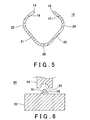
- a space 45 is provided over the processing surface 43 to avoid the edges 12 and 14 of the sheet metal 10 which go upwards as a result of the bending process.
- Fig. 5 illustrates the cross-sectional shape of the sheet metal 10 which is observed after the sheet metal 10 is bent by using the tool 40 illustrated in Fig. 4. As illustrated in Fig. 5, the sheet metal 10 is inserted into the tool 40, and then bent so that the middle of the distance from the edge 14 of the sheet metal 10 to the edges of the convex portions 16 coincides with the middle points of the processing surfaces 41 and 43 of the tool 40.
- a bent portion 26 with an arc-like cross-section is similarly formed, in addition to the bent portions 22 and 24 which are formed by the bending process using the tool 30 and have are-like cross-section.
- not-bent portions 21 and 23 are left between the bent portions 22 and 26, and between the bent portions 24 and 26.
- Fig. 6 illustrates the shape of a tool 50 which is used in the last bending process to be performed on the sheet metal 10 illustrated in Fig. 5.
- the tool 50 includes a die 52, a punch 54 and a core die 56.
- the die 52 has therein a processing surface 51 with an arc-like cross-sectional shape, which is formed so as to slightly protrude from the upper surface of the die 52.
- the punch 54 has a processing surface 53 similarly with an arc-like cross-sectional shape, which is positioned upper than the lower end surface of the punch 54.
- the side portions surrounding the processing surface 51 have shapes complementary to the shape of the end portion of the punch 54 excluding the processing surface 53.
- the tool 50 is configured in such a manner that, when the punch 54 is moved downward, the side portions surrounding the processing surface 51 does not come into a contact with the end portion of the punch 54 excluding the processing surface 53.
- the core die 56 is a round bar having an outer diameter which is substantially the same as the internal diameter of the cylindrical rod 20 (the final product). When used, the core die 56 is placed within the sheet metal 10 which has been bent by using the tool 40.
- the sheet metal 10 which has been bent by using the tool 40 is inserted into the die 52 of the tool 50 having the above-described configuration, so that the external side of the bent portion 26 becomes in contact with the internal side of the processing surface 51. After this, the core die 56 is placed within the sheet metal 10.
- the punch 54 is moved down. As a result, the edge 14 of the sheet metal 10 comes close to the edge 12 having the convex portions 16, so that the convex portions 16 are fitted into the concave portions 18. Following this, the punch 54 is further pressed down, so that the portions in the vicinity of the edges 12 and 14 containing the convex portions 16 and concave portions 18 are shaped into an arc as a whole, between the processing surface 53 of the punch 54 and the core die 56.
- the sheet metal 10 containing the not-bent portions 21 and 23 is bent between the lower portion of the core die 56 and the processing surface 51 of the die 52. Therefore, the bending process by using the tool 50 shapes the sheet metal 10 into a hollow cylinder having a ring-like cross-section as a whole. Note that the above-described sheet metal 10 is formed into the cylindrical rod 20 which has an outer diameter of approximately 5 mm.
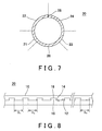
- Fig. 7 illustrates the cross-sectional shape of the cylindrical rod 20 which is manufactured by using the tool 50 illustrated in Fig. 6.
- the series of bending processes performed by using the tools 30,40 and 50 bends the entire sheet metal 10 at a uniform bending rate, thereby producing the cylindrical rod 20.
- the entire sheet metal 10 is bent at the same bending rate, including the convex portions 16. Therefore, the manufactured cylindrical rod 20 has high circularity.
- the convex portions 16 and concave portions 18 are fitted into each other.
- the sheet metal 10 may suffer from incorrect deformation. To avoid this, it is necessary to carefully determine the shape of the processing surface 53 of the punch 54 so that the convex portions 16 and concave portions 18 are smoothly fitted into each other.
- the edges 12 and 14 are brought close to each other while the tangential lines of the edges 12 and 14 are kept in such a state as to intersect with each other when seen at each of the cross-sections of the cylindrical rod 20 which are perpendicular to the longitudinal direction of the cylindrical rod 20. In this way, the wide sections of the convex portions 16 are caused to pass through the wide sections of the concave portion 18.
- the above-described method makes it possible to process the sheet metal 10 smoothly, and prevents the sheet metal 10 from being incorrectly deformed.
- Fig. 8 illustrates the bonding portion of the cylindrical rod 20. As illustrated in Fig. 8, the edges 12 and 14 are in tight contact with each other. Also, the convex portions 16 and concave portions 18 are fitted into each other. In addition, the intervals ( D 1 to D x ) between the convex portions 16 are the same over the entire length of the cylindrical rod 20.
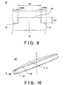
- Fig. 9 illustrates, in the enlarged state, how the convex portions 16 and concave portions 18 are fitted into each other in the cylindrical rod 20 illustrated in Fig. 8.
- the convex portions 16 have such a shape that the width is larger at the edge than at the root
- the concave portions 18 have such a shape that the width is smaller at the side closer to the edge 14 than at the side further from the edge 14.
- the fitted convex portions 16 and concave portions 18 are prevented from being disconnected from each other even when the spring back caused by the elasticity of the sheet metal 10 creates a force extending in the direction along the circumference of the cylindrical rod 20.
- the cylindrical rod 20 can be directly used as a shaft product without welding, adhering and/or other processes.
- the convex portions 16 and concave portions 18 may have any shapes, as long as the convex portions 16 and concave portions 18 have portions therein which are capable of withstanding the spring back. This is explained in detail.
- the convex portions 16 have a very large width in the longitudinal direction of the cylindrical rod 20
- the fitted convex portions 16 and concave portions 18 may be disconnected from each other by the buckling of the convex portions 16 in the longitudinal direction of the cylindrical rod 20.
- the strength of the convex portions 16 may be enhanced by increasing the length of a portion of each convex portion 16 which is in the vicinity of the middle in the longitudinal direction of the cylindrical rod 20.
- each convex portion 16 may have, in at least a portion thereof, such a shape that the width is larger at the edge than at the root and each concave portion 18 has a shape complementary to the shape of the convex portion 16, each convex portion 16 may have a different shape in the remaining portion.
- the convex portions 16 may each include a substantially disk-like portion and a connecting portion that connects part of the circumference of the disk to the sheet metal 10.
- each concave portion 18 at the edge 14 is 5 mm
- the height of each convex portion 16 (in other words, the depth of each concave portion 18) is 1.4 mm as written in the drawing.
- the width of each convex portion 16 is larger by 0.05 mm on each of the left and right sides at the edge than at the root (in other words, the width of each concave portion 18 is larger by 0.05 mm on each of the left and right sides at the bottom than at the opening.)
- the bending process can manufacture a cylindrical rod having high circularity, by repeating a bending step with a reduced amount of bending.
- the cylindrical shape can be obtained only by means of the bending process, without the bonding process performed based on welding, adhering or the like and can be maintained, by forming complementary concave portions and convex portions at the edges of the sheet metal that is subjected to the bending process and fitting the formed concave portions and convex portions to each other.
- Fig. 10 schematically illustrates the curve of the above-described cylindrical rod 20.
- the bonding portion 28 of the sheet metal 10 is positioned on the upper side and that there is an X-Y coordinate system which intersects with the axis direction of the cylindrical rod 20 at right angles.
- the middle point of the cylindrical rod 20 in the longitudinal direction of the cylindrical rod 20 may be displaced in the Y axis direction (the vertical curve) or in the X direction (the horizontal curve).
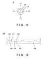
- Fig. 11 illustrates the directions of the above-mentioned vertical and horizontal curves, in terms of the cross-section of the cylindrical rod 20 which is perpendicular to the arrow line A in Fig. 10.
- the positive values are plotted in the upper or right section.
- the amount of curve preferably has a small absolute value, irrespectively of whether the amount has a positive or negative value.
- the cylindrical rod 20 when the cylindrical rod 20 has high circularity as explained above but has large curve, the cylindrical rod 20 is not suitable, particularly, for being used as a rotation axis.
- Fig. 12 illustrates a cylindrical rod 120 relating to an embodiment which addresses the above mentioned horizontal curve or a horizontal component of the curve.
- convex portions 126 and concave portions 121 are alternately formed at equal intervals on an edge 124 of sheet metal 129 which is used to form the cylindrical rod 120 according to the present embodiment, and convex portions 123 and concave portions 128 are alternately formed at equal intervals on an edge 122 of the sheet metal 129.
- the sheet metal 129 has a longer developed length.
- the sheet metal 129 has a symmetrical shape in terms of the direction along the shorter sides of the sheet metal 129. Therefore, the bending process can be performed with high accuracy.
- the stresses occurring between the fitted convex portion 126 and concave portion 128 and between the fitted convex portion 123 and concave portion 121 are dispersed in a symmetrical manner, the horizontal curve of the cylindrical rod 120 can be reduced.
- Fig. 13 illustrates a cylindrical rod 130 relating to another embodiment which also addresses the horizontal curve.
- the numbers of convex portions 136 and concave portions 131 formed on an edge 134 of sheet metal 139 are respectively different from the numbers of convex portions 133 and concave portions 138 formed on an edge 132 of the sheet metal 139, according to the present embodiment.
- This configuration is effective when the above-described curve of the cylindrical rod 130 is insignificant at the respective ends of the cylindrical rod 130 in the longitudinal direction, and significant in the middle portion.
- the configuration relating to the present embodiment can solve the problem of curve when the material for and the configuration of the cylindrical rod 130 is such that complex vertical curve is generated
- Fig. 14 illustrates a cylindrical rod 140 relating to another embodiment which addresses the horizontal curve.
- the spaces formed between convex portions 143 are used as concave portions 148, and the spaces between convex portions 146 are used as concave portions 141 on the edges of sheet metal 149 in the cylindrical rod 140. Therefore, the edges have shapes symmetrical to each other. As a result, the horizontal curve is prevented from occurring.
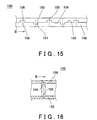
- Fig.15 illustrates a cylindrical rod 150 relating to an embodiment which addresses the above-mentioned vertical curve or a vertical component of the curve.
- the cylindrical rod 150 relating to the present embodiment is configured similarly to the cylindrical rod 120 illustrated in Fig. 12.
- convex portions 156 and concave portions 151 are alternately provided on an edge 154 of sheet metal 159
- convex portions 153 and concave portions 158 are alternately provided on an edge 152 of the sheet metal 159.
- the convex portions 156 and 153 are provided alternately on the edges 154 and 152
- the concave portions 151 and 158 are provided alternately on the edges 154 and 152.
- the cylindrical rod 150 has notches 155 formed at the positions at which the convex portions 153 and 156 and the concave portions 158 and 151 are respectively located.
- the notches 155 are formed on the internal side of the sheet metal 159 which forms the cylindrical rod 150 in such a manner as to reduce the thickness of the sheet metal 159, and extend in the direction along the circumference of the sheet metal 159.
- Fig. 16 illustrates the cross-section of the cylindrical rod 150 illustrated in Fig. 15 along the arrow line B.
- the notches 155 are grooves formed in the sheet metal 159 which forms the cylindrical rod 150. When formed at such positions, the notches 155 lower the rigidity of the sheet metal 159.
- Such a configuration alleviates the influence of the stresses created in the axis direction by the fitted convex portions 156 and concave portions 15 8 and the fitted convex portions 153 and concave portions 151. As a result, the vertical curve of the cylindrical rod 150 can be reduced.
- the notches 155 are formed on the internal surface of the cylindrical rod 150 considering the circularity of the circumference of the cylindrical rod 150.
- the notches 155 may be formed on the external surface of the cylindrical rod 150 without a problem, depending on how the cylindrical rod 150 is to be used.
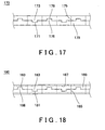
- Fig. 17 illustrates how notches 175 are arranged on a cylindrical rod 170 relating to another embodiment which also addresses the vertical curve.
- convex portions 176 and 173 and concave portions 178 and 171 are arranged in the cylindrical rod 170 in the same manner as in the embodiment illustrated in Fig. 12.
- the notches 175 are positioned between the convex portions 176 and 173 or between the concave portions 178 and 171. This configuration also alleviates the influence of the stresses extending at the bonding portion in the axis direction. As a result, the vertical curve can be reduced.
- Fig. 18 illustrates how notches 185 and 187 are arranged in a cylindrical rod 180 relating to another embodiment.
- convex portions 186 and 183, concave portions 188 and 181, and the notches 185 extending in the direction along the circumference are arranged in the cylindrical rod 180 in the same manner as the corresponding constituents in the cylindrical rod 170 illustrated in Fig. 17. Also, these constituents achieve the same effects as the corresponding constituents of the cylindrical rod 170.
- a plurality of notches 187 are additionally provided so as to extend in the axial direction of the cylindrical rod 180.
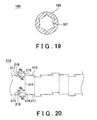
- Fig. 19 illustrates a cross-section obtained by cutting the cylindrical rod 180 illustrated in Fig. 18 along a plane perpendicular to the longitudinal direction.
- the notches 187 are formed on the internal surface of the cylindrical rod 180 at equal intervals.
- the notches 187 are also formed in order to reduce the thickness of the sheet metal 189, similarly to the notches 185.
- the notches 187 are provided so as to alleviate the influence of the stresses created in the direction along the circumference of the sheet metal 189.
- the present embodiment achieves the effect of maintaining the high circularity of the cylindrical rod 180.
- the cylindrical rods 150, 170 and 180 illustrated in Figs. 15 to 19 can be manufactured, for example, by using as the raw material sheet metal in which notches are formed in advance.
- Fig. 20 illustrates the shape of sheet metal 219 which is used as the raw material to form a cylindrical rod 210 relating to another embodiment. Similarly to the sheet metal 10 illustrated in Fig. 1, the sheet metal 219 also has a rectangular shape as a whole. In Fig. 20, however, only part of the sheet metal 219 is shown, in the enlarged state, for the purpose of showing more clearly the shapes of convex portions 211 and concave portions 213.
- the convex portions 211 and concave portions 213 are alternately provided on each of the edges 215 and 217 of the sheet metal 219.
- the convex portions 211 and concave portions 213 have shapes complementary to each other.
- the convex portions 211 and concave portions 213 on the edge 215 are formed at the positions opposing, with respect to the longitudinal direction of the sheet metal 219, the positions of the concave portions 213 and convex portions 211 formed on the edge 217, as indicated by the dotted lines in Fig. 20.
- the convex portions 211 and concave portions 213 have a width W 1 .
- the convex portions 211 and concave portions 213 have a width W 2 , which is larger than the width W 1 , at the other side which is positioned further away from the edges 215 and 217.
- the convex portions 211 and concave portions 213 each have a pair of side edges which are adjacent to the edges 215 and 217.
- One of the side edges forming the pair is a straight side edge 216 which forms a right angle with respect to the edge 215 or 217, and the other is a slant side edge 218 which forms an acute angle with respect to the edge 215 or 217.
- the straight side edges 216 of the convex portions 211 and concave portions 213 on each of the edges 215 and 217 in the present embodiment are formed on one of the sides of the convex portions 211, and the straight side edges 216 of the concave portions 213 are formed on the other side of the concave portions 213 in terms of the longitudinal direction of the sheet metal 219.
- Fig. 21 illustrates, in the enlarged state, part of the bonding portion of the cylindrical rod 210 which is manufactured by bending the sheet metal 219 illustrated in Fig. 20.
- the constituents of the cylindrical rod 210 which are already mentioned with reference to Fig. 20 are assigned the same reference numerals and not repeatedly explained.
- the convex portions 211 and concave portions 213 are fitted to each other at the portion of the cylindrical rod 210 where the edges 215 and 217 are bonded to each other.
- both of the convex portions 211 and concave portions 213 are shaped such that the width is larger at the side thereof which is positioned further away from the edges 215 and 217 than at the side thereof on the edges 215 and 217. Therefore, even when the spring back of the sheet metal 219 is generated, the fitted convex portions 211 and concave portions 213 keeps the edges 215 and 217 bonded to each other.
- the straight side edges 216 of the convex portions 211 and concave portions 213 oppose each other in the longitudinal direction.
- an upper bonding portion 212 and a lower bonding portion 214 of the sheet metal 219 which are defined in the bonded portion illustrated in Fig. 21, are likely to be displaced in different directions which oppose each other in the longitudinal direction of the cylindrical rod 210.
- the straight side edges 216 form a right angle with respect to the directions of the displacement, and are in contact with each other. This configuration prevents the displacement. Since the straight side edges 216 can be formed more accurately than the slant side edges 218, the straight side edges 216 have a small interval therebetween. For this reason, the cylindrical rod 210 has high torsional rigidity.
- Fig. 22 illustrates, in the enlarged state, part of the bonded portion of a cylindrical rod 220 relating to another embodiment.
- convex portions 221 and concave portions 223 formed in sheet metal 229 which constitutes the cylindrical rod 220 respectively have the same shapes as the corresponding constituents of the cylindrical rod 210 illustrated in Fig. 21.
- the straight side edges 216 of all the convex portions 221 and concave portions 223 are formed on the right side in the drawing.
- the convex portions 221 and concave portions 223 are arranged at equal internals (the interval D), and, at the same time, the straight side edges 216 are arranged at equal intervals (the internal D ) in the longitudinal direction of the cylindrical rod 220.
- the cylindrical rod 220 uniformly has high torsional rigidity in the longitudinal direction thereof.
- the present invention can provide a cylindrical rod which is manufactured by bending sheet metal and has high circularity and linearity.
- the cylindrical rod relating to the present invention can be used in place of a solid metal round bar member. Therefore, the present invention can reduce the raw material cost for many machines and tools which have been forced to use the solid members which are manufactured by the cutting technique due to the issues relating to the accuracy.
- the cylindrical rod relating to the present invention is lighter than the solid members, the present invention can reduce the friction loss of machines during the operation as well as the weight of the machines.
Abstract
A cylindrical rod 20 is formed by bending sheet metal 10 so as to bond together a pair of edges 12 and 14 of the sheet metal 10. The cylindrical rod 20 includes therein (i) convex portions 16 each of which protrudes from the edge 12 and includes a sub-portion whose width is larger at a side thereof more distant from the edge 12 than at a side thereof less distant from the edge 12, and (ii) concave portions 18 which are formed on the edge 14, have a shape complementary to the shape of the convex portions 16, and are fitted into the convex portions 16. A cylindrical rod which has high circularity and high linearity, in other words, which hardly has vertical and horizontal curves can be provided.
Description
- The present invention relates to a cylindrical rod. More particularly, the present invention relates to a cylindrical rod which is manufactured by bending sheet metal, and a manufacturing method of such a cylindrical rod.
- This patent application incorporates herein by reference the contents of a
Japanese Patent Application No. 2005-077574 filed on March 17, 2005 Japanese Patent Application No. 2006-043955 filed on February 21, 2006 - A number of techniques have been developed to manufacture cylindrical products by bending sheet metal. One of those techniques is disclosed in Patent Document 1 mentioned below According to the technique disclosed in Patent Document 1, relatively thin sheet metal is bent so that a tube with a small diameter is manufactured. In more detail, Patent Document 1 suggests using a core roll that has substantially the same internal diameter as a target cylindrical product, a pair of pressing rolls that are pressed against the core roll so as to rotate together with the core roll, and a guide belt that is provided so as to connect the respective rolls and to form a unique path. With these rolls and guide belt, the sheet metal is shaped while being in a tight contact with the core roll. Patent Document 1 explains that this technique enables the sheet metal to be shaped without causing barrel-like deformation.
Patent Document 1: UnexaminedJapanese Patent Application Publication No. 2003-245721 - Such cylindrical products may be desired to be utilized in place of solid metal round bars having a small diameter which are manufactured by means of the cutting technique, for the purpose of lowering the cost, for example. However, no cylindrical rod products have been developed which have satisfactory quality in terms of the characteristics such as the circularrity of the circumference and the linearity in the axis direction.
- To solve the above-mentioned problems, a first embodiment of the present invention provides a cylindrical rod which is formed by bonding together a pair of opposing edges of sheet metal. Here, each of the opposing edges has (i) convex portions each of which protrudes from the edge and includes a sub-portion whose width is larger at a side thereof more distant from the edge than at a side thereof less distant from the edge, and (ii) concave portions each of which dents from the edge and includes a sub-portion whose width is larger at a side thereof more distant from the edge than at a side thereof less distant from the edge, and the convex portions and the concave portions of one of the opposing edges are fitted into the concave portions and the convex portions of the other of the opposing edges. With such a configuration, the spring back of the sheet metal does not cause the bonded edges to be detached from each other, and the shape of the cylindrical rod is maintained without a bonding step performed by techniques including welding. In addition, since the sheet metal subjected to the bending process has a long developed length, the beading process can be performed excellently.
- According to an embodiment, the cylindrical rod has a linear section which forms substantially a right angle with respect to each of the opposing edges, and the linear section is adjacent to the edge. With such a configuration, the linear sections of the concave and convex portions are brought into contact with each other, so as to improve the torsional rigidity of the cylindrical rod.
- According to another embodiment, the linear sections are arranged at equal intervals in a longitudinal direction of the cylindrical rod. With such a configuration, the cylindrical rod can have uniform physical characteristics along the entire length. As a result, local deformation can be prevented.
- According to another embodiment, the linear section is formed on the same side in each of the convex and concave portions in a longitudinal direction of the cylindrical rod. With such a configuration, the concave and convex portions can be also arranged at equal intervals, Therefore, the cylindrical rod can have even more uniform physical characteristics. As a result, the cylindrical rod can have uniform physical characteristics along the entire length, thereby preventing local deformation more effectively.
- According to another embodiment, a plurality of notches which extend in a direction along a circumference of the cylindrical rod are provided so as to be adjacent to each other in an axis direction. With such a configuration, the stresses generated in the axis direction of the cylindrical rod are alleviated, and the cylindrical rod is prevented from being deformed, for example, curved.
- According to another embodiment, the plurality of notches are positioned at the convex and concave portions. With such a configuration, the stresses generated by the fitted convex and concave portions are alleviated, so as to maintain the linearity in the axis direction.
- According to another embodiment, the plurality of notches are positioned between the convex and concave portions in the axis direction. With such a configuration, the residual stresses in the entire cylindrical rod are alleviated, so as to maintain the linearity in the axis direction.
- According to a second embodiment of the present invention, the plurality of notches which extend in the direction along the circumference of the cylindrical rod are provided on an internal surface of the cylindrical rod so as to be adjacent to each other in the axis direction in the cylindrical rod. With such a configuration, the cylindrical rod has a smooth surface, and can be similarly treated to a solid round bar member.
- According to another embodiment, a plurality of notches which extend in the axis direction are additionally provided in the cylindrical rod. With such a configuration, the residual stresses in the direction along the circumference of the cylindrical rod can be alleviated, so as to maintain high circularity.
- A third embodiment of the present invention provides a manufacturing method for manufacturing a cylindrical rod by bending sheet metal so as to bond together a pair of opposing edges of the sheet metal. Here, the cylindrical rod is characterized in that each of cross-sections which are perpendicular to a longitudinal direction of the cylindrical rod has a circular shape. The manufacturing method sequentially includes a preparing step of forming the sheet metal in which each of the opposing edges has (i) convex portions each of which protrudes from the edge and includes a sub-portion whose width is larger at a side thereof more distant from the edge than at a side thereof less distant from the edge, and (ii) concave portions each of which dents from the edge and includes a sub-portion whose width is larger at a side thereof more distant from the edge than at a side thereof less distant from the edge, a preliminary step of bending the sheet metal in such a manner that, when seen in each of the cross-sections which are perpendicular to the longitudinal direction of the cylindrical rod, portions of the sheet metal in a vicinity of respective edges of the sheet metal excluding the convex portions form arcs, an intermediate step of bending the sheet metal in such a manner that, when seen in each of the cross-sections which are perpendicular to die longitudinal direction of the cylindrical rod, a portion of the sheet metal in a vicinity of a middle of the sheet metal is shaped like an arc, and a completing step of bending the sheet metal across an entire width thereof in such a manner that, when seen in the cross-sections which are perpendicular to the longitudinal direction of the cylindrical rod, the sheet metal forms a circle, and fitting the convex portions and the concave portions to each other. With such a manufacturing method, the convex and concave portions having varying width are smoothly fitted to each other. The manufactured cylindrical rod is not deformed again by the spring back, and can maintain the shape without requiring a bonding step performed by using techniques including welding.
- According to another embodiment, the convex portions and the concave portions are fitted to each other after the edges of the sheet metal are brought close to each other in the step of bending the sheet metal so as to bond together the pair of edges in the manufacturing method. In this way, THE wide sections of the convex portions and the narrow sections of the concave portions are prevented from interfering with each other during the process in which the edges of the sheet metal are bonded to each other. As a result, the sheet metal is prevented from being deformed.
- Here, all the necessary features of the present invention are not listed in the summary. The sub-combinations of the features may become the invention.
-
- Fig. 1 illustrates the shape of
sheet metal 10 which is a raw material of acylindrical rod 20 relating to the present invention. - Fig. 2 is a cross-sectional view illustrating a
tool 30 which is used in the initial bending process to be performed on thesheet metal 10. - Fig. 3 illustrates the cross-sectional shape of the
sheet metal 10 which is observed after the bending process is performed on thesheet metal 10 by using thetool 30 illustrated in Fig. 2. - Fig. 4 is a cross-sectional view illustrating a
tool 40 which is used in the next bending process to be performed on thesheet metal 10. - Fig. 5 illustrates the cross-sectional shape of the
sheet metal 10 which is observed after the bending process is performed on thesheet metal 10 by using thetool 40 illustrated in Fig. 4. - Fig. 6 is a cross-sectional view illustrating a
tool 50 which is used in the last bending process to be performed on thesheet metal 10. - Fig. 7 illustrates the cross-sectional shape of the
sheet metal 10 which is observed after thesheet metal 10 has been formed into thecylindrical rod 20. - Fig. 8 illustrates the bonding portion of the
cylindrical rod 20 and howconcave portions 18 andconvex portions 16 are arranged. - Fig. 9 illustrates the bonding portion of the
cylindrical rod 20 in the enlarged state. - Fig. 10 schematically illustrates the curve of the
cylindrical rod 20. - Fig. 11 illustrates, in a cross-sectional manner, the direction in which the
cylindrical rod 20 is curved. - Fig. 12 illustrates the bonding portion of a
cylindrical rod 120 relating to another embodiment. - Fig. 13 illustrates the bonding portion of a
cylindrical rod 130 relating to another embodiment. - Fig. 14 illustrates the bonding portion of a
cylindrical rod 140 relating to another embodiment - Fig. 15 illustrates how
notches 155 are arranged in acylindrical rod 150 relating to another embodiment - Fig. 16 illustrates the cross-section of the
cylindrical rod 150 illustrated in Fig. 15 along the arrow line B. - Fig. 17 illustrates how
notches 175 are arranged in acylindrical rod 170 relating to another embodiment. - Fig. 18 illustrates how
notches cylindrical rod 180 relating to another embodiment. - Fig. 19 is a cross-sectional view illustrating the
cylindrical rod 180 illustrated in Fig. 18. - Fig. 20 Illustrates the shape of
sheet metal 219 relating to another embodiment. - Fig. 21 illustrates, in the enlarged state, part of the bonding portion of a
cylindrical rod 210 which is manufactured by bending thesheet metal 219. - Fig. 22 illustrates, in the enlarged state, part of the bonding portion of a
cylindrical rod 220 relating to another embodiment. - Hereinafter, some embodiments of the present invention will be described. The embodiments do not limit the invention according to the claims, and all the combinations of the features described in the embodiments are not necessarily essential to means provided by aspects of the invention.
- Fig. 1 illustrates the shape of
sheet metal 10 which is a raw material of acylindrical rod 20 relating to the present invention. As illustrated in Fig. 1, thesheet metal 10 has a rectangular shape as a whole, and is bent in such a manner that a pair of opposingedges cylindrical rod 20 is formed and the longitudinal direction of thecylindrical rod 20 is considered to be the axis direction. Here, thesheet metal 10 is 314 mm in the longitudinal direction, and has a length of 10 mm from theedge 12 to theedge 14. - On the
edge 12 of thesheet metal 10, a plurality ofconvex portions 16 are provided at intervals. Theconvex portions 16 protrude from theedge 12. On theedge 14, a plurality ofconcave portions 18 are formed at intervals. Theconcave portions 18 have a depth extending from theedge 14 towards theedge 12. In addition, each of theconvex portions 16 is arranged at the same position as a corresponding me of theconcave portions 18 with respect to the longitudinal direction of thesheet metal 10. - Fig. 2 illustrates the shape of a
tool 30 which is used in the initial bending process to be performed on theshed metal 10. As illustrated in Fig. 2, thetool 30 includes adie 32 and apunch 34 which haveprocessing surfaces die 32 and punch 34 are flat in the middle portion thereof, and have a cross-sectional shape like an arc of approximately 90 degrees at the respective edges. - The
tool 30 extends in a direction perpendicular to the plane containing therein the sheet of paper on which Fig. 2 is shown, with the cross-sectional shape illustrated in Fig. 2 being maintained. The processing surfaces of thedie 32 and punch 34 are the same in width as thesheet metal 10 when theconvex portions 16 andconcave portions 18 are ignored. Here, thesheet metal 10 is inserted into thetool 30 having the above-described configuration in such a manner that the longitudinal direction of thesheet metal 10 matches the direction perpendicular to the plane containing therein the sheet of paper on which Fig. 2 is shown. - Fig. 3 illustrates the cross-sectional shape of the
sheet metal 10 which is observed after thesheet metal 10 is bent by using thetool 30 illustrated in Fig. 2. As illustrated in Fig. 3, the respective edges of thesheet metal 10 extending in the longitudinal direction are bent, so as to formbent portions die 32 and punch 34 have sizes determined in correspondence with the size of theentire sheet metal 10 as previously mentioned, both of the edges of thesheet metal 10 are bent so as to form an arc-like cross-section, except for the portions in the vicinity of theconvex portions 16 andconcave portions 18. - Fig. 4 illustrates the shape of a
tool 40 which is used in the next bending process to be performed on thesheet metal 10 illustrated in Fig.3. As illustrated in Fig. 4, thetool 40 includes adie 42 and apunch 44. To be more specific, thedie 42 has therein aprocessing surface 41 with an are-like cross-section that is open at the upper side thereof. On the other band, thepunch 44 has, at the lower end thereof, aprocessing surface 43 with an are-like cross-section. In addition, a space 45 is provided over theprocessing surface 43 to avoid theedges sheet metal 10 which go upwards as a result of the bending process. - Fig. 5 illustrates the cross-sectional shape of the
sheet metal 10 which is observed after thesheet metal 10 is bent by using thetool 40 illustrated in Fig. 4. As illustrated in Fig. 5, thesheet metal 10 is inserted into thetool 40, and then bent so that the middle of the distance from theedge 14 of thesheet metal 10 to the edges of theconvex portions 16 coincides with the middle points of the processing surfaces 41 and 43 of thetool 40. - As a result of the above bending process, a
bent portion 26 with an arc-like cross-section is similarly formed, in addition to thebent portions tool 30 and have are-like cross-section. Here, not-bent portions bent portions bent portions - Fig. 6 illustrates the shape of a
tool 50 which is used in the last bending process to be performed on thesheet metal 10 illustrated in Fig. 5. As illustrated in Fig. 6, thetool 50 includes a die 52, apunch 54 and acore die 56. Thedie 52 has therein aprocessing surface 51 with an arc-like cross-sectional shape, which is formed so as to slightly protrude from the upper surface of thedie 52. On the other hand, thepunch 54 has aprocessing surface 53 similarly with an arc-like cross-sectional shape, which is positioned upper than the lower end surface of thepunch 54. - The side portions surrounding the
processing surface 51 have shapes complementary to the shape of the end portion of thepunch 54 excluding theprocessing surface 53. Thetool 50 is configured in such a manner that, when thepunch 54 is moved downward, the side portions surrounding theprocessing surface 51 does not come into a contact with the end portion of thepunch 54 excluding theprocessing surface 53. The core die 56 is a round bar having an outer diameter which is substantially the same as the internal diameter of the cylindrical rod 20 (the final product). When used, the core die 56 is placed within thesheet metal 10 which has been bent by using thetool 40. - The
sheet metal 10 which has been bent by using thetool 40 is inserted into thedie 52 of thetool 50 having the above-described configuration, so that the external side of thebent portion 26 becomes in contact with the internal side of theprocessing surface 51. After this, the core die 56 is placed within thesheet metal 10. - With the
sheet metal 10 being set within thetool 50 as described above, thepunch 54 is moved down. As a result, theedge 14 of thesheet metal 10 comes close to theedge 12 having theconvex portions 16, so that theconvex portions 16 are fitted into theconcave portions 18. Following this, thepunch 54 is further pressed down, so that the portions in the vicinity of theedges convex portions 16 andconcave portions 18 are shaped into an arc as a whole, between theprocessing surface 53 of thepunch 54 and the core die 56. - At the same time, the
sheet metal 10 containing the not-bent portions processing surface 51 of thedie 52. Therefore, the bending process by using thetool 50 shapes thesheet metal 10 into a hollow cylinder having a ring-like cross-section as a whole. Note that the above-describedsheet metal 10 is formed into thecylindrical rod 20 which has an outer diameter of approximately 5 mm. - Fig. 7 illustrates the cross-sectional shape of the
cylindrical rod 20 which is manufactured by using thetool 50 illustrated in Fig. 6. As illustrated in Fig. 7, the series of bending processes performed by using thetools entire sheet metal 10 at a uniform bending rate, thereby producing thecylindrical rod 20. It should be noted here that theentire sheet metal 10 is bent at the same bending rate, including theconvex portions 16. Therefore, the manufacturedcylindrical rod 20 has high circularity. - During the process in which the
sheet metal 10 having the cross-sectional shape illustrated in the Fig. 5 is processed so as to have the cross-sectional shape illustrated in Fig. 7, theconvex portions 16 andconcave portions 18 are fitted into each other. Here, if the wide sections of theconvex portions 16 are inserted into the narrow sections of theconcave portions 18, thesheet metal 10 may suffer from incorrect deformation. To avoid this, it is necessary to carefully determine the shape of theprocessing surface 53 of thepunch 54 so that theconvex portions 16 andconcave portions 18 are smoothly fitted into each other. To be specific, theedges edges cylindrical rod 20 which are perpendicular to the longitudinal direction of thecylindrical rod 20. In this way, the wide sections of theconvex portions 16 are caused to pass through the wide sections of theconcave portion 18. The above-described method makes it possible to process thesheet metal 10 smoothly, and prevents thesheet metal 10 from being incorrectly deformed. - Fig. 8 illustrates the bonding portion of the
cylindrical rod 20. As illustrated in Fig. 8, theedges convex portions 16 andconcave portions 18 are fitted into each other. In addition, the intervals (D1 to Dx ) between theconvex portions 16 are the same over the entire length of thecylindrical rod 20. - Fig. 9 illustrates, in the enlarged state, how the
convex portions 16 andconcave portions 18 are fitted into each other in thecylindrical rod 20 illustrated in Fig. 8. As illustrated in Fig. 9, theconvex portions 16 have such a shape that the width is larger at the edge than at the root On the other hand, theconcave portions 18 have such a shape that the width is smaller at the side closer to theedge 14 than at the side further from theedge 14. With such a configuration, the fittedconvex portions 16 andconcave portions 18 are prevented from being disconnected from each other even when the spring back caused by the elasticity of thesheet metal 10 creates a force extending in the direction along the circumference of thecylindrical rod 20. For this reason, thecylindrical rod 20 can be directly used as a shaft product without welding, adhering and/or other processes. - The
convex portions 16 andconcave portions 18 may have any shapes, as long as theconvex portions 16 andconcave portions 18 have portions therein which are capable of withstanding the spring back. This is explained in detail. For example, when theconvex portions 16 have a very large width in the longitudinal direction of thecylindrical rod 20, the fittedconvex portions 16 andconcave portions 18 may be disconnected from each other by the buckling of theconvex portions 16 in the longitudinal direction of thecylindrical rod 20. In this case, the strength of theconvex portions 16 may be enhanced by increasing the length of a portion of eachconvex portion 16 which is in the vicinity of the middle in the longitudinal direction of thecylindrical rod 20. Alternatively, the sheet metal which is used as the raw material may be sharply bent so that the stresses are easily concentrated. Therefore, the sheet metal may be sharply bent in such a manner as to form a smooth shape as a whole. Alternatively, under the condition that eachconvex portion 16 has, in at least a portion thereof, such a shape that the width is larger at the edge than at the root and eachconcave portion 18 has a shape complementary to the shape of theconvex portion 16, eachconvex portion 16 may have a different shape in the remaining portion. For example, theconvex portions 16 may each include a substantially disk-like portion and a connecting portion that connects part of the circumference of the disk to thesheet metal 10. - According to the exemplary embodiment shown in Fig. 9, the opening width of each
concave portion 18 at theedge 14 is 5 mm, and the height of each convex portion 16 (in other words, the depth of each concave portion 18) is 1.4 mm as written in the drawing. The width of eachconvex portion 16 is larger by 0.05 mm on each of the left and right sides at the edge than at the root (in other words, the width of eachconcave portion 18 is larger by 0.05 mm on each of the left and right sides at the bottom than at the opening.) - As described in the above section, the bending process can manufacture a cylindrical rod having high circularity, by repeating a bending step with a reduced amount of bending. In addition, the cylindrical shape can be obtained only by means of the bending process, without the bonding process performed based on welding, adhering or the like and can be maintained, by forming complementary concave portions and convex portions at the edges of the sheet metal that is subjected to the bending process and fitting the formed concave portions and convex portions to each other.
- Fig. 10 schematically illustrates the curve of the above-described
cylindrical rod 20. As illustrated in Fig. 10, it is assumed that thebonding portion 28 of thesheet metal 10 is positioned on the upper side and that there is an X-Y coordinate system which intersects with the axis direction of thecylindrical rod 20 at right angles. Under these assumptions, the middle point of thecylindrical rod 20 in the longitudinal direction of thecylindrical rod 20 may be displaced in the Y axis direction (the vertical curve) or in the X direction (the horizontal curve). - Fig. 11 illustrates the directions of the above-mentioned vertical and horizontal curves, in terms of the cross-section of the
cylindrical rod 20 which is perpendicular to the arrow line A in Fig. 10. As indicated in Fig. 11, the positive values are plotted in the upper or right section. However, the amount of curve preferably has a small absolute value, irrespectively of whether the amount has a positive or negative value. In other words, when thecylindrical rod 20 has high circularity as explained above but has large curve, thecylindrical rod 20 is not suitable, particularly, for being used as a rotation axis. - Fig. 12 illustrates a
cylindrical rod 120 relating to an embodiment which addresses the above mentioned horizontal curve or a horizontal component of the curve. As illustrated in Fig. 12,convex portions 126 andconcave portions 121 are alternately formed at equal intervals on anedge 124 ofsheet metal 129 which is used to form thecylindrical rod 120 according to the present embodiment, andconvex portions 123 andconcave portions 128 are alternately formed at equal intervals on anedge 122 of thesheet metal 129. With such a configuration, thesheet metal 129 has a longer developed length. At die same time, thesheet metal 129 has a symmetrical shape in terms of the direction along the shorter sides of thesheet metal 129. Therefore, the bending process can be performed with high accuracy. Furthermore, since the stresses occurring between the fittedconvex portion 126 andconcave portion 128 and between the fittedconvex portion 123 andconcave portion 121 are dispersed in a symmetrical manner, the horizontal curve of thecylindrical rod 120 can be reduced. - Fig. 13 illustrates a
cylindrical rod 130 relating to another embodiment which also addresses the horizontal curve. As illustrated in Fig. 13, the numbers ofconvex portions 136 andconcave portions 131 formed on anedge 134 ofsheet metal 139 are respectively different from the numbers ofconvex portions 133 andconcave portions 138 formed on anedge 132 of thesheet metal 139, according to the present embodiment. This configuration is effective when the above-described curve of thecylindrical rod 130 is insignificant at the respective ends of thecylindrical rod 130 in the longitudinal direction, and significant in the middle portion. As a result, the configuration relating to the present embodiment can solve the problem of curve when the material for and the configuration of thecylindrical rod 130 is such that complex vertical curve is generated - Fig. 14 illustrates a
cylindrical rod 140 relating to another embodiment which addresses the horizontal curve. As illustrated in Fig. 14, the spaces formed betweenconvex portions 143 are used asconcave portions 148, and the spaces betweenconvex portions 146 are used asconcave portions 141 on the edges ofsheet metal 149 in thecylindrical rod 140. Therefore, the edges have shapes symmetrical to each other. As a result, the horizontal curve is prevented from occurring. - Fig.15 illustrates a
cylindrical rod 150 relating to an embodiment which addresses the above-mentioned vertical curve or a vertical component of the curve. As illustrated in Fig. 15, thecylindrical rod 150 relating to the present embodiment is configured similarly to thecylindrical rod 120 illustrated in Fig. 12. In detail,convex portions 156 andconcave portions 151 are alternately provided on anedge 154 ofsheet metal 159, andconvex portions 153 andconcave portions 158 are alternately provided on anedge 152 of thesheet metal 159. In addition, theconvex portions edges concave portions edges cylindrical rod 150 hasnotches 155 formed at the positions at which theconvex portions concave portions notches 155 are formed on the internal side of thesheet metal 159 which forms thecylindrical rod 150 in such a manner as to reduce the thickness of thesheet metal 159, and extend in the direction along the circumference of thesheet metal 159. - Fig. 16 illustrates the cross-section of the
cylindrical rod 150 illustrated in Fig. 15 along the arrow line B. As illustrated in Fig. 16, thenotches 155 are grooves formed in thesheet metal 159 which forms thecylindrical rod 150. When formed at such positions, thenotches 155 lower the rigidity of thesheet metal 159. Such a configuration alleviates the influence of the stresses created in the axis direction by the fittedconvex portions 156 and concave portions 15 8 and the fittedconvex portions 153 andconcave portions 151. As a result, the vertical curve of thecylindrical rod 150 can be reduced. - In the above-described embodiment, the
notches 155 are formed on the internal surface of thecylindrical rod 150 considering the circularity of the circumference of thecylindrical rod 150. However, thenotches 155 may be formed on the external surface of thecylindrical rod 150 without a problem, depending on how thecylindrical rod 150 is to be used. - Fig. 17 illustrates how
notches 175 are arranged on acylindrical rod 170 relating to another embodiment which also addresses the vertical curve. As illustrated in Fig. 17, similarly to the embodiment illustrated in Fig. 15,convex portions concave portions cylindrical rod 170 in the same manner as in the embodiment illustrated in Fig. 12. Differently from the embodiment illustrated in Fig. 15, however, thenotches 175 are positioned between theconvex portions concave portions - Fig. 18 illustrates how
notches cylindrical rod 180 relating to another embodiment. As illustrated in Fig. 18,convex portions concave portions 188 and 181, and thenotches 185 extending in the direction along the circumference are arranged in thecylindrical rod 180 in the same manner as the corresponding constituents in thecylindrical rod 170 illustrated in Fig. 17. Also, these constituents achieve the same effects as the corresponding constituents of thecylindrical rod 170. According to the present embodiment, however, a plurality ofnotches 187 are additionally provided so as to extend in the axial direction of thecylindrical rod 180. - Fig. 19 illustrates a cross-section obtained by cutting the
cylindrical rod 180 illustrated in Fig. 18 along a plane perpendicular to the longitudinal direction. As illustrated in Fig. 19, thenotches 187 are formed on the internal surface of thecylindrical rod 180 at equal intervals. Thenotches 187 are also formed in order to reduce the thickness of thesheet metal 189, similarly to thenotches 185. To be more specific, thenotches 187 are provided so as to alleviate the influence of the stresses created in the direction along the circumference of thesheet metal 189. With this configuration, the present embodiment achieves the effect of maintaining the high circularity of thecylindrical rod 180. Note that thecylindrical rods - Fig. 20 illustrates the shape of
sheet metal 219 which is used as the raw material to form acylindrical rod 210 relating to another embodiment. Similarly to thesheet metal 10 illustrated in Fig. 1, thesheet metal 219 also has a rectangular shape as a whole. In Fig. 20, however, only part of thesheet metal 219 is shown, in the enlarged state, for the purpose of showing more clearly the shapes ofconvex portions 211 andconcave portions 213. - As illustrated in Fig. 20, the
convex portions 211 andconcave portions 213 are alternately provided on each of theedges sheet metal 219. Here, theconvex portions 211 andconcave portions 213 have shapes complementary to each other. In addition, theconvex portions 211 andconcave portions 213 on theedge 215 are formed at the positions opposing, with respect to the longitudinal direction of thesheet metal 219, the positions of theconcave portions 213 andconvex portions 211 formed on theedge 217, as indicated by the dotted lines in Fig. 20. - At the side which is positioned on the
edges convex portions 211 andconcave portions 213 have a width W1. However, theconvex portions 211 andconcave portions 213 have a width W2, which is larger than the width W1, at the other side which is positioned further away from theedges convex portions 211 andconcave portions 213 each have a pair of side edges which are adjacent to theedges straight side edge 216 which forms a right angle with respect to theedge slant side edge 218 which forms an acute angle with respect to theedge convex portions 211 andconcave portions 213 on each of theedges convex portions 211 are formed on one of the sides of theconvex portions 211, and the straight side edges 216 of theconcave portions 213 are formed on the other side of theconcave portions 213 in terms of the longitudinal direction of thesheet metal 219. - Fig. 21 illustrates, in the enlarged state, part of the bonding portion of the
cylindrical rod 210 which is manufactured by bending thesheet metal 219 illustrated in Fig. 20. The constituents of thecylindrical rod 210 which are already mentioned with reference to Fig. 20 are assigned the same reference numerals and not repeatedly explained. - As illustrated in Fig. 21, the
convex portions 211 andconcave portions 213 are fitted to each other at the portion of thecylindrical rod 210 where theedges convex portions 211 andconcave portions 213 are shaped such that the width is larger at the side thereof which is positioned further away from theedges edges sheet metal 219 is generated, the fittedconvex portions 211 andconcave portions 213 keeps theedges - Here, the straight side edges 216 of the
convex portions 211 andconcave portions 213 oppose each other in the longitudinal direction. When thecylindrical rod 210 is influenced by a stress which twists thecylindrical rod 210, anupper bonding portion 212 and alower bonding portion 214 of thesheet metal 219, which are defined in the bonded portion illustrated in Fig. 21, are likely to be displaced in different directions which oppose each other in the longitudinal direction of thecylindrical rod 210. According to thecylindrical rod 210, however, the straight side edges 216 form a right angle with respect to the directions of the displacement, and are in contact with each other. This configuration prevents the displacement. Since the straight side edges 216 can be formed more accurately than the slant side edges 218, the straight side edges 216 have a small interval therebetween. For this reason, thecylindrical rod 210 has high torsional rigidity. - Fig. 22 illustrates, in the enlarged state, part of the bonded portion of a
cylindrical rod 220 relating to another embodiment. As illustrated in Fig. 22,convex portions 221 andconcave portions 223 formed insheet metal 229 which constitutes thecylindrical rod 220 respectively have the same shapes as the corresponding constituents of thecylindrical rod 210 illustrated in Fig. 21. In thecylindrical rod 220, however, the straight side edges 216 of all theconvex portions 221 andconcave portions 223 are formed on the right side in the drawing. Therefore, theconvex portions 221 andconcave portions 223 are arranged at equal internals (the interval D), and, at the same time, the straight side edges 216 are arranged at equal intervals (the internal D) in the longitudinal direction of thecylindrical rod 220. As a result, thecylindrical rod 220 uniformly has high torsional rigidity in the longitudinal direction thereof. - As described above in detail, the present invention can provide a cylindrical rod which is manufactured by bending sheet metal and has high circularity and linearity. The cylindrical rod relating to the present invention can be used in place of a solid metal round bar member. Therefore, the present invention can reduce the raw material cost for many machines and tools which have been forced to use the solid members which are manufactured by the cutting technique due to the issues relating to the accuracy. In addition, since the cylindrical rod relating to the present invention is lighter than the solid members, the present invention can reduce the friction loss of machines during the operation as well as the weight of the machines.
- While the embodiments of the present invention have been described, the technical scope of the invention is not limited to the above described embodiments. It is apparent to persons skilled in the art that various alternations and improvements can be added to the above-described embodiments. It is also apparent from the scope of the claims that the embodiments added with such alternations or improvements can be included in the technical scope of the invention.
Claims (11)
- A cylindrical rod which is formed by bonding together a pair of opposing edges of sheet metal, wherein
each of the opposing edges has (i) convex portions each of which protrudes from the edge and includes a sub-portion whose width is larger at a side thereof more distant from the edge than at a side thereof less distant from the edge, and (ii) concave portions each of which dents from the edge and includes a sub-portion whose width is larger at a side thereof more distant from the edge than at a side thereof less distant from the edge, and
the convex portions and the concave portions of one of the opposing edges are fitted into the concave portions and the convex portions of the other of the opposing edges. - The cylindrical rod as set forth in Claim 1, wherein
a periphery of each of the convex and concave portions has a linear section which forms substantially a right angle with respect to a corresponding one of the opposing edges, and the linear section is adjacent to the corresponding one of the opposing edges. - The cylindrical rod as set forth in Claim 2, wherein
the linear sections are arranged at equal intervals in a longitudinal direction of the cylindrical rod. - The cylindrical rod as set forth in one of Claims 2 and 3, wherein
the linear section is formed on the same side in each of the convex and concave portions in a longitudinal direction of the cylindrical rod. - The cylindrical rod as set forth in Claim 1, wherein
a plurality of notches which extend in a direction along a circumference of the cylindrical rod are provided so as to be adjacent to each other in an axis direction. - The cylindrical rod as set forth in Claim 5, wherein
the plurality of notches are positioned at the convex and concave portions. - The cylindrical rod as set forth in Claim 5, wherein
the plurality of notches are positioned between the convex and concave portions in the axis direction. - A cylindrical rod which is formed by bonding together a pair of opposing edges of sheet metal, wherein
a plurality of notches which extend in a direction along a circumference of the cylindrical rod are provided on an internal surface of the cylindrical rod so as to be adjacent to each other in an axis direction. - The cylindrical rod as set forth in Claim 8, wherein
a plurality of notches which extend in the axis direction are additionally provided so as to be adjacent to each other in the direction along the circumference of the cylindrical rod. - A method of manufacturing a cylindrical rod by bending sheet metal so as to bond together a pair of opposing edges of the sheet metal, the cylindrical rod being characterized in that each of cross-sections which are perpendicular to a longitudinal direction of the cylindrical rod has a circular shape, the manufacturing method sequentially comprising:a preparing step of forming the sheet metal in which each of the opposing edges has (i) convex portions each of which protrudes from the edge and includes a sub-portion whose width is larger at a side thereof more distant from the edge than at a side thereof less distant from the edge, and (ii) concave portions each of which dents from the edge and includes a sub-portion whose width is larger at a side thereof more distant from the edge than at a side thereof less distant from the edge;a preliminary step of bending the sheet metal in such a manner that, when seen in each of the cross-sections which are perpendicular to the longitudinal direction of the cylindrical rod, portions of the sheet metal in a vicinity of respective edges of the sheet metal excluding the convex portions form arcs;an intermediate step of bending the sheet metal in such a manner that, when seen in each of the cross-sections which are perpendicular to the longitudinal direction of the cylindrical rod, a portion of the sheet metal in a vicinity of a middle of the sheet metal is shaped like an arc; anda completing step of bending the sheet metal across an entire width thereof in such a manner that, when seen in the cross-sections which are perpendicular to the longitudinal direction of the cylindrical rod, the sheet metal forms a circle, and fitting the convex porticos and the concave portions to each other.
- The method as set forth in Claim 10, wherein
in the completing step, the convex portions and the concave portions are fitted to each other after the edges of the sheet metal are brought close to each other.
Applications Claiming Priority (3)
| Application Number | Priority Date | Filing Date | Title |
|---|---|---|---|
| JP2005077574 | 2005-03-17 | ||
| JP2006043955A JP2006289496A (en) | 2005-03-17 | 2006-02-21 | Cylindrical shaft and method of manufacturing the same |
| PCT/JP2006/304294 WO2006098183A1 (en) | 2005-03-17 | 2006-03-06 | Cylindrical shaft and method of manufacturing the same |
Publications (1)
| Publication Number | Publication Date |
|---|---|
| EP1867403A1 true EP1867403A1 (en) | 2007-12-19 |
Family
ID=36991531
Family Applications (1)
| Application Number | Title | Priority Date | Filing Date |
|---|---|---|---|
| EP06715314A Withdrawn EP1867403A1 (en) | 2005-03-17 | 2006-03-06 | Cylindrical shaft and method of manufacturing the same |
Country Status (5)
| Country | Link |
|---|---|
| US (1) | US7610938B2 (en) |
| EP (1) | EP1867403A1 (en) |
| JP (1) | JP2006289496A (en) |
| CN (1) | CN101893032A (en) |
| WO (1) | WO2006098183A1 (en) |
Cited By (1)
| Publication number | Priority date | Publication date | Assignee | Title |
|---|---|---|---|---|
| EP2590241A1 (en) * | 2011-05-30 | 2013-05-08 | Panasonic Corporation | Cell block and method for manufacturing same |
Families Citing this family (25)
| Publication number | Priority date | Publication date | Assignee | Title |
|---|---|---|---|---|
| KR20090023037A (en) * | 2007-08-28 | 2009-03-04 | 가부시키가이샤 히타치세이사쿠쇼 | Plasma display device |
| JP5042073B2 (en) * | 2008-02-29 | 2012-10-03 | 愛三工業株式会社 | Fuel injection valve |
| US9021947B2 (en) * | 2008-06-16 | 2015-05-05 | Humaneyes Technologies Ltd. | Method and an apparatus for processing a lenticular printing substrate |
| JP2010184806A (en) | 2009-02-13 | 2010-08-26 | Seiko Epson Corp | Carrier roller, carrying unit and printer |
| JP5453831B2 (en) * | 2009-02-13 | 2014-03-26 | セイコーエプソン株式会社 | Printing device |
| JP5267187B2 (en) * | 2009-02-13 | 2013-08-21 | セイコーエプソン株式会社 | Cylindrical shaft, transport roller, transport unit, and printing apparatus |
| JP5446305B2 (en) * | 2009-02-13 | 2014-03-19 | セイコーエプソン株式会社 | Printing device |
| US9180702B2 (en) | 2009-02-13 | 2015-11-10 | Seiko Epson Corporation | Cylindrical shaft, transport roller, transport unit and printing apparatus |
| JP5402054B2 (en) * | 2009-02-13 | 2014-01-29 | セイコーエプソン株式会社 | Conveying roller, conveying unit, and printing apparatus |
| JP5353460B2 (en) | 2009-06-12 | 2013-11-27 | セイコーエプソン株式会社 | Conveying roller, conveying apparatus and printing apparatus |
| JP5509722B2 (en) * | 2009-08-10 | 2014-06-04 | セイコーエプソン株式会社 | Printing device |
| JP2011073420A (en) * | 2009-10-02 | 2011-04-14 | Seiko Epson Corp | Printer |
| JP5696357B2 (en) * | 2009-11-27 | 2015-04-08 | セイコーエプソン株式会社 | Conveying roller manufacturing method, conveying roller, printing apparatus |
| JP2011121682A (en) * | 2009-12-09 | 2011-06-23 | Seiko Epson Corp | Print device, transport unit, transport roller, and method of producing the transport roller |
| JP2011126631A (en) * | 2009-12-16 | 2011-06-30 | Seiko Epson Corp | Transportation roller, transportation unit, printing apparatus, and method of manufacturing transportation roller |
| JP5428854B2 (en) * | 2009-12-29 | 2014-02-26 | セイコーエプソン株式会社 | Conveying roller, conveying unit, printing apparatus, and conveying roller manufacturing method |
| JP5641228B2 (en) * | 2010-02-10 | 2014-12-17 | セイコーエプソン株式会社 | Recording device |
| JP2011184149A (en) | 2010-03-09 | 2011-09-22 | Seiko Epson Corp | Conveying device and printing device |
| JP5510139B2 (en) * | 2010-07-12 | 2014-06-04 | セイコーエプソン株式会社 | Manufacturing method of cylindrical shaft |
| JP5712589B2 (en) | 2010-12-07 | 2015-05-07 | セイコーエプソン株式会社 | Printing device |
| JP5866985B2 (en) * | 2011-11-09 | 2016-02-24 | セイコーエプソン株式会社 | Manufacturing method of cylindrical shaft |
| JP6019907B2 (en) * | 2012-08-08 | 2016-11-02 | セイコーエプソン株式会社 | Recording device |
| JP6391272B2 (en) * | 2014-03-31 | 2018-09-19 | キヤノン株式会社 | Roller member, roller support mechanism, and image forming apparatus |
| JP6784572B2 (en) | 2015-12-09 | 2020-11-11 | キヤノン株式会社 | Electrophotographic rollers, their manufacturing methods and electrophotographic equipment |
| JP6881941B2 (en) | 2016-10-21 | 2021-06-02 | キヤノン株式会社 | Image forming device |
Family Cites Families (22)
| Publication number | Priority date | Publication date | Assignee | Title |
|---|---|---|---|---|
| US595035A (en) * | 1897-12-07 | Emile stranger and alfred chobert | ||
| US556819A (en) * | 1896-03-24 | Sheet-metal tube | ||
| US1863873A (en) * | 1929-07-15 | 1932-06-21 | Bundy Tubing Co | Method of making tubes |
| US1999818A (en) * | 1931-01-22 | 1935-04-30 | Patrick J Mcintyre | Method of forming tubing |
| US2202909A (en) * | 1937-09-27 | 1940-06-04 | Thompson Prod Inc | Drag link body and method of making same |
| US2317198A (en) * | 1940-02-23 | 1943-04-20 | Midland Steel Prod Co | Sheet metal forming equipment |
| US2362817A (en) * | 1942-09-28 | 1944-11-14 | Continental Can Co | Method of making sheet metal containers |
| US3050649A (en) * | 1958-08-18 | 1962-08-21 | Amherst Metal Products Inc | Motor brush holder |
| US3099238A (en) * | 1959-11-23 | 1963-07-30 | Alice J Barger | Can body and method of forming the same |
| US3301992A (en) * | 1963-08-14 | 1967-01-31 | Taylor Winfield Corp | Method for joining flat metal stock |
| US3543227A (en) * | 1968-03-26 | 1970-11-24 | Hughes Aircraft Co | Contact spring for electrical socket contact |
| JPS5543360A (en) * | 1978-09-21 | 1980-03-27 | Ito Kogyo Kk | Metal pipe |
| DE3201108A1 (en) * | 1982-01-15 | 1983-07-28 | Siemens AG, 1000 Berlin und 8000 München | LOCKING SYSTEM FOR A CUFF OF SHRINKABLE MATERIAL |
| JPS63303218A (en) | 1987-06-02 | 1988-12-09 | Daido Metal Kogyo Kk | Joint type roll bush bearing having same-shaped joint part at both ends of joint |
| CH679945A5 (en) * | 1989-04-04 | 1992-05-15 | Oetiker Hans Maschinen | |
| JPH05156780A (en) * | 1991-12-03 | 1993-06-22 | Mitsubishi Materials Corp | Composite panel and its manufacture |
| US6391414B1 (en) * | 1997-03-07 | 2002-05-21 | Pharmacia Ab | Structure and method for joining parts |
| JPH11156440A (en) * | 1997-11-27 | 1999-06-15 | Kinugawa Rubber Ind Co Ltd | Forming method of metal tube |
| US6745448B2 (en) * | 2000-02-04 | 2004-06-08 | Ricoh Company, Ltd. | Pipe body and forming method of the same |
| JP2003285303A (en) * | 2002-01-22 | 2003-10-07 | Yutaka Ogino | Method for curving material, and material therefor |
| JP2004001003A (en) * | 2002-05-29 | 2004-01-08 | Kuno Kinzoku Kogyo Kk | Method for joining planar member |
| JP2007160352A (en) * | 2005-12-14 | 2007-06-28 | Seiko Epson Corp | Cylindrical shaft, manufacturing method of cylindrical shaft, and fixing roller using cylindrical shaft |
-
2006
- 2006-02-21 JP JP2006043955A patent/JP2006289496A/en not_active Withdrawn
- 2006-03-06 EP EP06715314A patent/EP1867403A1/en not_active Withdrawn
- 2006-03-06 CN CN201010246766XA patent/CN101893032A/en active Pending
- 2006-03-06 WO PCT/JP2006/304294 patent/WO2006098183A1/en active Application Filing
-
2007
- 2007-09-17 US US11/856,444 patent/US7610938B2/en active Active
Non-Patent Citations (1)
| Title |
|---|
| See references of WO2006098183A1 * |
Cited By (2)
| Publication number | Priority date | Publication date | Assignee | Title |
|---|---|---|---|---|
| EP2590241A1 (en) * | 2011-05-30 | 2013-05-08 | Panasonic Corporation | Cell block and method for manufacturing same |
| EP2590241A4 (en) * | 2011-05-30 | 2013-12-18 | Panasonic Corp | Cell block and method for manufacturing same |
Also Published As
| Publication number | Publication date |
|---|---|
| US7610938B2 (en) | 2009-11-03 |
| WO2006098183A1 (en) | 2006-09-21 |
| CN101893032A (en) | 2010-11-24 |
| JP2006289496A (en) | 2006-10-26 |
| US20080121008A1 (en) | 2008-05-29 |
Similar Documents
| Publication | Publication Date | Title |
|---|---|---|
| US7610938B2 (en) | Cylindrical rod and method for manufacturing the same | |
| KR101996155B1 (en) | Method for manufacturing molded article, mold, and tubular molded article | |
| EP2857118B1 (en) | Method for manufacturing tube shaped part with different diameters and forming mold | |
| EP3202503A1 (en) | Method of manufacturing press-formed product, and press-formed product | |
| EP3006128B1 (en) | Method of manufacturing a welded steel pipe | |
| JP2007203342A (en) | Method for manufacturing cylindrical shaft | |
| EP3597322A1 (en) | Press mold and method for manufacturing steel pipe | |
| JP5270816B2 (en) | Channel material | |
| EP3957411A1 (en) | Manufacturing method and manufacturing device for link component | |
| JP4923597B2 (en) | Method for forming cylindrical shaft product and mold | |
| JP2009195986A (en) | Cylindrical shaft | |
| EP2837437B1 (en) | Method for producing flangeless closed-cross-section-structure component having curved shape | |
| US10857582B2 (en) | Method of manufacturing tooth-shaped component, and tooth-shaped component | |
| JPH06284679A (en) | Manufacture of comb teeth of stator of stepping motor | |
| JP5593191B2 (en) | Metal pipe manufacturing equipment | |
| JP4881152B2 (en) | gear | |
| US11833570B2 (en) | Method for manufacturing shaped part | |
| JP4924653B2 (en) | Manufacturing method of cylindrical shaft | |
| JP5520542B2 (en) | Manufacturing method and manufacturing apparatus for thin metal tube | |
| EP4279192A1 (en) | Burring method, burring die, burring device, and burred article | |
| US11511329B2 (en) | Method for obtaining a three-dimensional curve in a tubular product, and method for manufacturing complex-curvature tubular products | |
| JP2002001432A (en) | Method for manufacturing hollow rack shaft | |
| EP3694659B1 (en) | Rack bar manufacturing method | |
| WO2023189155A1 (en) | Rectangular can manufacturing method and rectangular can manufacturing device | |
| US11298734B2 (en) | Multi-axis roll-forming of stepped-diameter cylinder |
Legal Events
| Date | Code | Title | Description |
|---|---|---|---|
| PUAI | Public reference made under article 153(3) epc to a published international application that has entered the european phase |
Free format text: ORIGINAL CODE: 0009012 |
|
| 17P | Request for examination filed |
Effective date: 20071017 |
|
| AK | Designated contracting states |
Kind code of ref document: A1 Designated state(s): DE FR GB |
|
| DAX | Request for extension of the european patent (deleted) | ||
| RBV | Designated contracting states (corrected) |
Designated state(s): DE FR GB |
|
| STAA | Information on the status of an ep patent application or granted ep patent |
Free format text: STATUS: THE APPLICATION HAS BEEN WITHDRAWN |
|
| 18W | Application withdrawn |
Effective date: 20081231 |