EP1865585B1 - Gel-filled casing for electric connections - Google Patents
Gel-filled casing for electric connections Download PDFInfo
- Publication number
- EP1865585B1 EP1865585B1 EP07019086.3A EP07019086A EP1865585B1 EP 1865585 B1 EP1865585 B1 EP 1865585B1 EP 07019086 A EP07019086 A EP 07019086A EP 1865585 B1 EP1865585 B1 EP 1865585B1
- Authority
- EP
- European Patent Office
- Prior art keywords
- base
- cables
- gel
- openings
- casing
- Prior art date
- Legal status (The legal status is an assumption and is not a legal conclusion. Google has not performed a legal analysis and makes no representation as to the accuracy of the status listed.)
- Active
Links
- 230000008878 coupling Effects 0.000 claims description 9
- 238000010168 coupling process Methods 0.000 claims description 9
- 238000005859 coupling reaction Methods 0.000 claims description 9
- 230000000295 complement effect Effects 0.000 claims description 7
- 230000002427 irreversible effect Effects 0.000 claims description 4
- 230000002441 reversible effect Effects 0.000 claims description 2
- 210000002105 tongue Anatomy 0.000 description 13
- 239000007788 liquid Substances 0.000 description 2
- 238000010276 construction Methods 0.000 description 1
- 230000001419 dependent effect Effects 0.000 description 1
- 230000037431 insertion Effects 0.000 description 1
- 238000003780 insertion Methods 0.000 description 1
- 238000004519 manufacturing process Methods 0.000 description 1
- 239000000463 material Substances 0.000 description 1
- 230000002093 peripheral effect Effects 0.000 description 1
- 230000000379 polymerizing effect Effects 0.000 description 1
- 239000000126 substance Substances 0.000 description 1
- XLYOFNOQVPJJNP-UHFFFAOYSA-N water Substances O XLYOFNOQVPJJNP-UHFFFAOYSA-N 0.000 description 1
Images


Classifications
-
- H—ELECTRICITY
- H02—GENERATION; CONVERSION OR DISTRIBUTION OF ELECTRIC POWER
- H02G—INSTALLATION OF ELECTRIC CABLES OR LINES, OR OF COMBINED OPTICAL AND ELECTRIC CABLES OR LINES
- H02G15/00—Cable fittings
- H02G15/003—Filling materials, e.g. solid or fluid insulation
-
- H—ELECTRICITY
- H02—GENERATION; CONVERSION OR DISTRIBUTION OF ELECTRIC POWER
- H02G—INSTALLATION OF ELECTRIC CABLES OR LINES, OR OF COMBINED OPTICAL AND ELECTRIC CABLES OR LINES
- H02G15/00—Cable fittings
- H02G15/02—Cable terminations
- H02G15/06—Cable terminating boxes, frames or other structures
-
- H—ELECTRICITY
- H02—GENERATION; CONVERSION OR DISTRIBUTION OF ELECTRIC POWER
- H02G—INSTALLATION OF ELECTRIC CABLES OR LINES, OR OF COMBINED OPTICAL AND ELECTRIC CABLES OR LINES
- H02G15/00—Cable fittings
- H02G15/08—Cable junctions
- H02G15/10—Cable junctions protected by boxes, e.g. by distribution, connection or junction boxes
- H02G15/113—Boxes split longitudinally in main cable direction
-
- H—ELECTRICITY
- H02—GENERATION; CONVERSION OR DISTRIBUTION OF ELECTRIC POWER
- H02G—INSTALLATION OF ELECTRIC CABLES OR LINES, OR OF COMBINED OPTICAL AND ELECTRIC CABLES OR LINES
- H02G15/00—Cable fittings
- H02G15/08—Cable junctions
- H02G15/10—Cable junctions protected by boxes, e.g. by distribution, connection or junction boxes
- H02G15/115—Boxes split perpendicularly to main cable direction
-
- H—ELECTRICITY
- H01—ELECTRIC ELEMENTS
- H01R—ELECTRICALLY-CONDUCTIVE CONNECTIONS; STRUCTURAL ASSOCIATIONS OF A PLURALITY OF MUTUALLY-INSULATED ELECTRICAL CONNECTING ELEMENTS; COUPLING DEVICES; CURRENT COLLECTORS
- H01R4/00—Electrically-conductive connections between two or more conductive members in direct contact, i.e. touching one another; Means for effecting or maintaining such contact; Electrically-conductive connections having two or more spaced connecting locations for conductors and using contact members penetrating insulation
- H01R4/70—Insulation of connections
-
- H—ELECTRICITY
- H01—ELECTRIC ELEMENTS
- H01R—ELECTRICALLY-CONDUCTIVE CONNECTIONS; STRUCTURAL ASSOCIATIONS OF A PLURALITY OF MUTUALLY-INSULATED ELECTRICAL CONNECTING ELEMENTS; COUPLING DEVICES; CURRENT COLLECTORS
- H01R9/00—Structural associations of a plurality of mutually-insulated electrical connecting elements, e.g. terminal strips or terminal blocks; Terminals or binding posts mounted upon a base or in a case; Bases therefor
- H01R9/22—Bases, e.g. strip, block, panel
- H01R9/24—Terminal blocks
-
- Y—GENERAL TAGGING OF NEW TECHNOLOGICAL DEVELOPMENTS; GENERAL TAGGING OF CROSS-SECTIONAL TECHNOLOGIES SPANNING OVER SEVERAL SECTIONS OF THE IPC; TECHNICAL SUBJECTS COVERED BY FORMER USPC CROSS-REFERENCE ART COLLECTIONS [XRACs] AND DIGESTS
- Y10—TECHNICAL SUBJECTS COVERED BY FORMER USPC
- Y10S—TECHNICAL SUBJECTS COVERED BY FORMER USPC CROSS-REFERENCE ART COLLECTIONS [XRACs] AND DIGESTS
- Y10S439/00—Electrical connectors
- Y10S439/933—Special insulation
- Y10S439/936—Potting material or coating, e.g. grease, insulative coating, sealant or, adhesive
Definitions
- the present invention relates to a gel-filled casing for electric connections.
- Casing for electric connections are known from EP443694 , US 5828005 , US 6265665 , US 5397859 and US 4859809 . These documents disclose a casing for electric connections comprising two elements which can be reciprocally coupled in a reversible or irreversible manner and delimiting an internal cavity for a terminal box or similar device and a plurality of in/out openings for one or more cables which can be connected to the terminal box or similar device.
- the internal space of at least one of said two elements is filled with dielectric gel which occupies said space before the positioning of the terminal box or similar device into said cavity , that is to say it is provided with a predetermined quantity of dielectric gel which occupies its internal space.
- the present invention aims at simplifying the execution of junctions or connections of electric cables protected by the action of liquid substances or vapours in order to render them more efficient, safer and easier to execute.
- the present invention makes it possible to realize a water and vapours tight casing for electric connections which is very simple, safe, efficient and reliable, even after long periods in environments characterized by the presence of liquids and vapours and, at the same time, it ensures reduced manufacturing costs and is easy to use.
- the casing comprises a base body (100) with an internal housing (101) for a terminal box (3) or similar device and an upper element (102) which constitutes a cover element of said housing (101) and is provided with a plurality of extensions (114) orthogonal to its upper face.
- Said extensions (114) are provided with channel-shaped depressions (104).
- Said depressions in cooperation with corresponding depressions featured by the element (400) described below, delimit corresponding tubular guides for the cables connected to the terminal box (3).
- the internal bottom of base element (101) features a plurality of extensions (111) which emerge perpendicularly from the bottom itself and act as guides for the positioning of the terminal box (3).
- said coupling means consist of a first series of flexible tongues (103) having the shape of a reversed "J" whose base is in proximity to a peripheral edge of the upper or external face of the element (102) and of a second series of flexible tongues (105) having the shape of a reversed "J "with a hooked free end, the base thereof being in proximity to the edge of element (102) from which the tongues (103) of the first series emerge.
- said coupling means comprise a first and of a second series of eyelets (106,107) with vertical openings provided by the base element (100) in proximity to the upper edge of its external wall.
- each eyelet (107) of the second series of eyelets features a surface (108) which partially develops inside the eyelet itself and constitutes a guide element for the hooked part of corresponding tongue (105).
- a lower horizontal portion of said surface (108) constitutes a contrast element for said hooked part of tongue (105) and a holding element of the tongue itself when the device is assembled.
- the element (102) features an edge (110) having a predetermined height on its internal face (111), that is to say on the face which is opposite to the face (109) from which tongues (103) and (105) emerge.
- the face (111) of the element (102) is provided with two diametrically opposed flat extensions (112), which are orthogonal to the surface of the face (111) from which they emerge. Said extensions (112) are positioned more internally and are longer than said edge (110).
- Both faces (109,111) of element (102) are provided with a plurality of removable portions (113) in correspondence of the above mentioned extensions (114).
- the removal of one or more said removable portions (113) -this operation can be carried out by means of a tool such as a screwdriver or similar tool- provides corresponding in/out openings for the cables connected to the terminal box (3).
- each complementary element consists of a body with two hollow section cavities (401) positioned side by side, each of them being positioned in front of a corresponding extension (114) of element (102) when the casing is assembled.
- the connection of elements (400) to extensions (114) of element (102), so as to allow each cavity (104) of extensions (114) to be positioned opposite to a corresponding cavity (401) of an element (400), provides the above mentioned in/out tubular guides for the cables connected to terminal box (3).
- Said extensions (114) of element (102) and complementary elements (400) are provided with means for their reciprocal coupling.
- Said means comprise a plurality of hooked tongues (140) which orthogonally project from the two longitudinal external edges (141) of said extensions (114) and a plurality of corresponding eyelets (410) featured by each element (400) at its external longitudinal edges (411). The coupling is carried out by introducing each tongue (140) into the corresponding eyelet (410).
- the base element (100) is filled with dielectric gel.
- the positioning of terminal box (3) inside cavity (101) filled with gel and the subsequent coupling of element (102) to base (100) determines a flow of gel which covers the whole terminal box, that is to say the connections between the terminal box and the cables which are joined to it, and penetrates the in/out guides of the cables so as to render the connections perfectly sealed.
- dielectric gel (G) can be of the Dow Corning Q3-6575 type, that is to say of the bi-component type which slowly polymerizes at ambient temperature or of the bi-component type which fast polymerizes at high temperatures.
- gel (G) is of the hot polymerized type, polymerizing at a temperature of 100°C.
- a casing for electric connections comprises a base element (200) and an upper element or cover (201).
- the base (200) accommodates the terminal box (3) to which the cables (5) are connected and is filled with dielectric gel (G) up to a predetermined level (LG).
- the cover element (201) is provided, on its top surface (201'), with a plurality of funnel-shaped in/out openings (202) for the passage of the cables (5), the larger base of said openings (202) being oriented towards the internal bottom of the base (200) when the casing is assembled.
- the cover element (201) is provided with a diagonally and upwardly, i.e.
- each fin (203) is intended to engage a corresponding hole (204) provided by the base element (200) in proximity of its top edge (205).
- the fins (203) make it possible to realize an irreversible coupling of the cover element (201) to the base (200).
- the cover element (201) is provided with side walls (209) developing below said fins (203) and intended to be positioned within the cavity (210) delimited by the side walls and the bottom of the base element (200).
- the cover element (201) is further provided, positioned on top and laterally of said funnel-shaped openings (202), with an appendix (206) cooperating with a detachable complementary element (207) to clamp the cables (5) exiting from the openings (202) once, as further described below, the casing assembling is completed.
- This casing is assembled as shown in Figs. 17-20 .
- the cables (5) connected to the terminal box (3) are inserted through the openings (202) of the cover element (201) and the terminal box is housed within the space delimited by the side walls (209) of the cover element (201), the top surface (300) of the terminal box (3) being oriented towards the external.
- the side walls (209) of the cover (201) are inserted into the base element (200) which is prefilled with the dielectric gel (G) up to the engagement of the fins (203) of the cover (201) into the openings (204) of the base (200).
- the dielectric gel flows through any available space and completely seals the electric connections.
- the terminal box (3) results positioned with its top surface (300) oriented towards the internal bottom of the base element (200).
- the cables (5) exiting from the openings (202) of the cover element (201) are clamped by said appendix (206) and said complementary element (207) which are joined together, on opposite sides with respect to the cables (5), by means of a screw (208).
Landscapes
- Insertion, Bundling And Securing Of Wires For Electric Apparatuses (AREA)
- Cable Accessories (AREA)
- Connector Housings Or Holding Contact Members (AREA)
- Connections Arranged To Contact A Plurality Of Conductors (AREA)
- Details Of Connecting Devices For Male And Female Coupling (AREA)
Description
- The present invention relates to a gel-filled casing for electric connections.
- Casing for electric connections are known from
EP443694 US 5828005 ,US 6265665 ,US 5397859 andUS 4859809 . These documents disclose a casing for electric connections comprising two elements which can be reciprocally coupled in a reversible or irreversible manner and delimiting an internal cavity for a terminal box or similar device and a plurality of in/out openings for one or more cables which can be connected to the terminal box or similar device. The internal space of at least one of said two elements is filled with dielectric gel which occupies said space before the positioning of the terminal box or similar device into said cavity , that is to say it is provided with a predetermined quantity of dielectric gel which occupies its internal space. -
US3806630 andWO97/13297 - The present invention aims at simplifying the execution of junctions or connections of electric cables protected by the action of liquid substances or vapours in order to render them more efficient, safer and easier to execute.
- According to the present invention, these results have been achieved by providing a casing whose features are indicated in claim 1. Further features of the present invention are the subject of the dependent claims.
- The present invention makes it possible to realize a water and vapours tight casing for electric connections which is very simple, safe, efficient and reliable, even after long periods in environments characterized by the presence of liquids and vapours and, at the same time, it ensures reduced manufacturing costs and is easy to use.
- These and other advantages and characteristics of the invention will be best understood by anyone skilled in the art from a reading of the following description in conjunction with the attached drawings given as a practical exemplification of the invention, but not to be considered in a limitative sense, wherein:
-
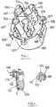
Fig. 1 is a perspective view of a casing for electric connections according to an example not claimed in the present invention; -
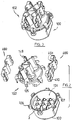
Fig. 2 is an exploded perspective view of the casing ofFig. 1 ; -
Fig. 3 is a perspective view of the casing shown inFig. 1 in a step preceding the coupling of the upper element to the base element; -
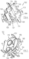
Fig. 4 is partial transverse section view of the base element of the casing shown inFig. 1 ; -
Fig. 5 is a perspective view of the base element of the casing shown inFig. 1 ; -
Fig. 6 is a perspective top view of the upper element of the casing shown inFig. 1 ; -
Fig. 7 is a perspective bottom view of the upper element of the casing shown inFig. 1 ; -
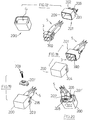
Fig. 8 is a perspective view of the cables clamping elements associated with the upper element of the casing shown inFig. 1 ; -
Fig. 9 is a front view of a casing according to an embodiment of the present invention; -
Fig. 10 is a side view of the casing shown inFig. 9 ; -
Fig. 11 is a vertical section view of the casing shown inFig. 9 ; -
Fig. 12 is a vertical section view of the casing shown inFig. 10 ; -
Fig. 13 is a vertical section view of the base element of the casing shown inFig. 9 ; -
Fig. 14 is a front view of the upper element of the casing shown inFig. 9 ; -
Figs. 15 and 16 are two vertical section views of the element shown inFig. 14 ; -
Figs. 17-20 illustrate the assembling of the casing shown inFig.9 . - With reference to the example shown in
Figs 1-8 of the enclosed drawing, the casing comprises a base body (100) with an internal housing (101) for a terminal box (3) or similar device and an upper element (102) which constitutes a cover element of said housing (101) and is provided with a plurality of extensions (114) orthogonal to its upper face. Said extensions (114) are provided with channel-shaped depressions (104). Said depressions, in cooperation with corresponding depressions featured by the element (400) described below, delimit corresponding tubular guides for the cables connected to the terminal box (3). The internal bottom of base element (101) features a plurality of extensions (111) which emerge perpendicularly from the bottom itself and act as guides for the positioning of the terminal box (3). Said elements (100) and (102) are provided with means for their reciprocal coupling. In particular, said coupling means consist of a first series of flexible tongues (103) having the shape of a reversed "J" whose base is in proximity to a peripheral edge of the upper or external face of the element (102) and of a second series of flexible tongues (105) having the shape of a reversed "J "with a hooked free end, the base thereof being in proximity to the edge of element (102) from which the tongues (103) of the first series emerge. Moreover, said coupling means comprise a first and of a second series of eyelets (106,107) with vertical openings provided by the base element (100) in proximity to the upper edge of its external wall. The tongues (103) of the first series of tongues are inserted in the eyelets (106) of the first series of eyelets and the tongues (105) of the second series of tongues are inserted in the eyelets (107) of the second series of eyelets. Each eyelet (107) of the second series of eyelets features a surface (108) which partially develops inside the eyelet itself and constitutes a guide element for the hooked part of corresponding tongue (105). A lower horizontal portion of said surface (108) constitutes a contrast element for said hooked part of tongue (105) and a holding element of the tongue itself when the device is assembled. - The element (102) features an edge (110) having a predetermined height on its internal face (111), that is to say on the face which is opposite to the face (109) from which tongues (103) and (105) emerge. The face (111) of the element (102) is provided with two diametrically opposed flat extensions (112), which are orthogonal to the surface of the face (111) from which they emerge. Said extensions (112) are positioned more internally and are longer than said edge (110).
- Both faces (109,111) of element (102) are provided with a plurality of removable portions (113) in correspondence of the above mentioned extensions (114). The removal of one or more said removable portions (113) -this operation can be carried out by means of a tool such as a screwdriver or similar tool- provides corresponding in/out openings for the cables connected to the terminal box (3).
- Corresponding complementary elements (400) are hooked on said extensions (114) and each of them features channel-shaped cavities (401) corresponding to those (104) provided by extensions (114). In the example illustrated in Figs 22-30, said extensions (114) are four. Accordingly, each complementary element consists of a body with two hollow section cavities (401) positioned side by side, each of them being positioned in front of a corresponding extension (114) of element (102) when the casing is assembled. The connection of elements (400) to extensions (114) of element (102), so as to allow each cavity (104) of extensions (114) to be positioned opposite to a corresponding cavity (401) of an element (400), provides the above mentioned in/out tubular guides for the cables connected to terminal box (3).
- Said extensions (114) of element (102) and complementary elements (400) are provided with means for their reciprocal coupling. Said means comprise a plurality of hooked tongues (140) which orthogonally project from the two longitudinal external edges (141) of said extensions (114) and a plurality of corresponding eyelets (410) featured by each element (400) at its external longitudinal edges (411). The coupling is carried out by introducing each tongue (140) into the corresponding eyelet (410).
- The base element (100) is filled with dielectric gel. The positioning of terminal box (3) inside cavity (101) filled with gel and the subsequent coupling of element (102) to base (100) determines a flow of gel which covers the whole terminal box, that is to say the connections between the terminal box and the cables which are joined to it, and penetrates the in/out guides of the cables so as to render the connections perfectly sealed. Fox example, dielectric gel (G) can be of the Dow Corning Q3-6575 type, that is to say of the bi-component type which slowly polymerizes at ambient temperature or of the bi-component type which fast polymerizes at high temperatures.
- Preferably, gel (G) is of the hot polymerized type, polymerizing at a temperature of 100°C.
- Reference being made to the example shown in
Figs. 9-20 , a casing for electric connections according to the present invention comprises a base element (200) and an upper element or cover (201). The base (200) accommodates the terminal box (3) to which the cables (5) are connected and is filled with dielectric gel (G) up to a predetermined level (LG). The cover element (201) is provided, on its top surface (201'), with a plurality of funnel-shaped in/out openings (202) for the passage of the cables (5), the larger base of said openings (202) being oriented towards the internal bottom of the base (200) when the casing is assembled. Moreover, the cover element (201) is provided with a diagonally and upwardly, i.e. centrifugally, oriented fin (203) on both external sides, said fins (203) being located in proximity of the lower end of said openings (202). The free end of each fin (203) is intended to engage a corresponding hole (204) provided by the base element (200) in proximity of its top edge (205). The fins (203) make it possible to realize an irreversible coupling of the cover element (201) to the base (200). The cover element (201) is provided with side walls (209) developing below said fins (203) and intended to be positioned within the cavity (210) delimited by the side walls and the bottom of the base element (200). The cover element (201) is further provided, positioned on top and laterally of said funnel-shaped openings (202), with an appendix (206) cooperating with a detachable complementary element (207) to clamp the cables (5) exiting from the openings (202) once, as further described below, the casing assembling is completed. - This casing is assembled as shown in
Figs. 17-20 . First, the cables (5) connected to the terminal box (3) are inserted through the openings (202) of the cover element (201) and the terminal box is housed within the space delimited by the side walls (209) of the cover element (201), the top surface (300) of the terminal box (3) being oriented towards the external. Then, the side walls (209) of the cover (201) are inserted into the base element (200) which is prefilled with the dielectric gel (G) up to the engagement of the fins (203) of the cover (201) into the openings (204) of the base (200). During said insertion, the dielectric gel flows through any available space and completely seals the electric connections. The terminal box (3) results positioned with its top surface (300) oriented towards the internal bottom of the base element (200). Finally, the cables (5) exiting from the openings (202) of the cover element (201) are clamped by said appendix (206) and said complementary element (207) which are joined together, on opposite sides with respect to the cables (5), by means of a screw (208). - Practically, all the construction details may vary in any equivalent way as far as the shape, dimensions, elements disposition, nature of the used materials are concerned, without nevertheless departing from the scope of the adopted solution idea and, thereby, remaining within the limits of the protection granted to the present patent.
Claims (3)
- Gel-filled casing for electric connections comprising a base element (200) having an internal volume filled with dielectric gel (G) and a covering or upper element (201) which can be reciprocally coupled in a reversible or irreversible manner to the base element (200), the latter delimiting an internal cavity (210) for a terminal box (3) or similar device to which one or more cables (5) are connected a plurality of in/out tubular guides for the said cables (5) being formed on the said covering or upper element (201), wherein the base (200) accommodates the terminal box (3) to which the cables (5) are connected and is filled with dielectric gel (G) up to a predetermined level (LG), and the cover element (201) is provided, on its top surface (201'), with a plurality of funnel-shaped in/out openings (202) for the passage of the cables (5), the said funnel-shaped in/out openings (202) having a larger base and smaller base, the larger base of said openings (202) being oriented towards the internal bottom of the base (200) when the casing is assembled, characterized in that the cover element (201) has an integrally formed appendix (206) cooperating with a detachable complementary element (207) to clamp the cables (5) exiting from the funnel-shaped openings, the appendix (206) and the complementary element (207) being positioned on top and laterally of said funnel-shaped openings (202).
- Gel-filled casing for electric connections according to claim 1 characterized in that the said cover element (201) is provided with a diagonally and upwardly, i.e. centrifugally, oriented fin (203) on both external sides, said fins (203) being located in proximity of the lower end of said openings (202), the free end of each fin (203) being intended to engage a corresponding hole (204) provided by the base element (200) in proximity of its top edge (205), the said fins (203) realizing an irreversible coupling of the cover element (201) to the base (200).
- Gel-filled casing for electric connections according to claim 2 characterized in that the said cover element (201) is provided with side walls (209) developing below said fins (203) and intended to be positioned within the cavity (210) delimited by the side walls and the bottom of the base element (200).
Applications Claiming Priority (2)
| Application Number | Priority Date | Filing Date | Title |
|---|---|---|---|
| IT000185A ITFI20050185A1 (en) | 2005-08-31 | 2005-08-31 | CASE FOR ELECTRICAL CONNECTIONS AND PROCEDURE FOR MANUFACTURING A SHEET |
| EP06001353A EP1760856B1 (en) | 2005-08-31 | 2006-01-23 | Casing for electric connections and process for manufacturing such a casing |
Related Parent Applications (1)
| Application Number | Title | Priority Date | Filing Date |
|---|---|---|---|
| EP06001353A Division EP1760856B1 (en) | 2005-08-31 | 2006-01-23 | Casing for electric connections and process for manufacturing such a casing |
Publications (3)
| Publication Number | Publication Date |
|---|---|
| EP1865585A2 EP1865585A2 (en) | 2007-12-12 |
| EP1865585A3 EP1865585A3 (en) | 2009-04-15 |
| EP1865585B1 true EP1865585B1 (en) | 2016-07-27 |
Family
ID=37459378
Family Applications (2)
| Application Number | Title | Priority Date | Filing Date |
|---|---|---|---|
| EP06001353A Active EP1760856B1 (en) | 2005-08-31 | 2006-01-23 | Casing for electric connections and process for manufacturing such a casing |
| EP07019086.3A Active EP1865585B1 (en) | 2005-08-31 | 2006-01-23 | Gel-filled casing for electric connections |
Family Applications Before (1)
| Application Number | Title | Priority Date | Filing Date |
|---|---|---|---|
| EP06001353A Active EP1760856B1 (en) | 2005-08-31 | 2006-01-23 | Casing for electric connections and process for manufacturing such a casing |
Country Status (6)
| Country | Link |
|---|---|
| US (2) | US7417190B2 (en) |
| EP (2) | EP1760856B1 (en) |
| CN (2) | CN1933267B (en) |
| ES (1) | ES2588686T3 (en) |
| IT (1) | ITFI20050185A1 (en) |
| TW (1) | TWI390802B (en) |
Families Citing this family (20)
| Publication number | Priority date | Publication date | Assignee | Title |
|---|---|---|---|---|
| ITFI20050185A1 (en) | 2005-08-31 | 2007-03-01 | Belisario Pini | CASE FOR ELECTRICAL CONNECTIONS AND PROCEDURE FOR MANUFACTURING A SHEET |
| ITFI20070151A1 (en) * | 2007-07-10 | 2009-01-11 | Steab S P A | PROTECTION BOX FOR ELECTRICAL CONNECTIONS. |
| ITFI20070150A1 (en) * | 2007-07-10 | 2009-01-11 | Steab S P A | BOX PROTECTION FOR ELECTRICAL CONNECTIONS |
| FR2926166B1 (en) * | 2008-01-08 | 2010-06-11 | Ge Energy Products France Snc | KIT OF TEMPERATURE SENSORS, IN PARTICULAR FOR COMBUSTION TURBINE. |
| DE202008003294U1 (en) | 2008-03-08 | 2009-07-23 | Weidmüller Interface GmbH & Co. KG | Connecting device for the conductors of two cables |
| US8084691B2 (en) | 2008-11-18 | 2011-12-27 | Tyco Electronics Corporation | Sealant-filled enclosures and methods for environmentally protecting a connection |
| WO2010059615A2 (en) * | 2008-11-18 | 2010-05-27 | Tyco Electronics Corporation | Sealant-filled enclosures and methods for environmentally protecting a connection |
| JP5281534B2 (en) * | 2009-10-05 | 2013-09-04 | ホシデン株式会社 | Terminal box |
| JP5600521B2 (en) * | 2010-08-25 | 2014-10-01 | パナソニック株式会社 | Power supply control device |
| DE102012009405B4 (en) | 2012-05-11 | 2016-02-04 | Pfisterer Kontaktsysteme Gmbh | Device for electrically connecting main conductors of a power supply cable, each having at least one branch conductor |
| US10939904B2 (en) * | 2014-07-08 | 2021-03-09 | Lsi Solutions, Inc. | Rotation adapter and receiver for minimally invasive surgical devices |
| US11103235B2 (en) | 2014-07-08 | 2021-08-31 | Lsi Solutions, Inc. | Rotation adapter and receiver for minimally invasive surgical devices |
| KR102693646B1 (en) * | 2017-11-15 | 2024-08-09 | 주식회사 엘지에너지솔루션 | Connector assembly with rounded edges |
| EP3791220B1 (en) | 2018-05-09 | 2023-07-05 | AFL Telecommunications LLC | Butt closures and bases therefor |
| US10840615B2 (en) | 2018-06-28 | 2020-11-17 | Te Connectivity Corporation | Connection enclosure assemblies, connector systems and methods for forming an enclosed connection between conductors |
| US11424582B2 (en) | 2019-11-21 | 2022-08-23 | Commscope Technologies Llc | Ganged coaxial connector assembly |
| US11431114B2 (en) | 2020-02-14 | 2022-08-30 | Te Connectivity Solutions Gmbh | Enclosed connection systems for forming an enclosed connection between conductors, and methods including same |
| US10996414B1 (en) | 2020-03-23 | 2021-05-04 | Afl Telecommunications Llc | Butt closures and bases therefor |
| US12078846B2 (en) | 2020-11-30 | 2024-09-03 | Afl Telecommunications Llc | Butt closures and bases therefor |
| IT202200014425A1 (en) | 2022-07-08 | 2024-01-08 | Leonardo Pini | Box protection for electrical connections. |
Family Cites Families (17)
| Publication number | Priority date | Publication date | Assignee | Title |
|---|---|---|---|---|
| US3504099A (en) * | 1968-08-01 | 1970-03-31 | Amp Inc | Electrical connections and insulating boot therefor |
| US3874760A (en) * | 1972-04-27 | 1975-04-01 | Bernell J Guthmiller | Sheathed electrical coupling |
| US3806630A (en) * | 1972-08-21 | 1974-04-23 | J Thompson | Encapsulated splice assembly for buried cables |
| US3937870A (en) * | 1974-08-08 | 1976-02-10 | Clemar Manufacturing Corporation | Device for insulating an electrical wire joint |
| US4643924A (en) * | 1985-03-25 | 1987-02-17 | Raychem Corporation | Protective article comprising an elastic gel |
| US4859809A (en) * | 1988-04-27 | 1989-08-22 | Raychem Corporation | Splice case |
| US5038003A (en) * | 1990-05-14 | 1991-08-06 | T & B Industries, Inc. | Waterproof electrical splice enclosure with specialized housing to prevent the wires from being removed from the waterproof material within the housing |
| CN1065160A (en) * | 1991-03-15 | 1992-10-07 | 雷伊化学公司 | Shell with single type component parts with gel-filled |
| WO1992022116A1 (en) * | 1991-06-07 | 1992-12-10 | Raychem Corporation | Hinged gel-filled security and environmental protection device |
| JP3081760B2 (en) * | 1993-11-10 | 2000-08-28 | 矢崎総業株式会社 | Waterproof protective cover |
| US5397859A (en) * | 1993-12-10 | 1995-03-14 | The Whitaker Corporation | Enclosure with sealant for spliced coaxial cables |
| US5777268A (en) * | 1995-10-06 | 1998-07-07 | Raychem Corporation | Splice closure for buried telecommunications cables |
| US5763835A (en) * | 1995-11-01 | 1998-06-09 | Raychem Corporation | Gel-filled closure |
| US5913692A (en) * | 1998-02-05 | 1999-06-22 | Targett; John N. | Electrical cord locking assembly |
| US6265665B1 (en) * | 1999-11-30 | 2001-07-24 | Homac Manufacturing Company | Gel-filled casing for an electrical connection and associated method |
| US6333463B1 (en) * | 2000-11-17 | 2001-12-25 | Tyco Electronics Corporation | Wire separators having sealant material reservoirs and cable splice closures employing such separators |
| ITFI20050185A1 (en) | 2005-08-31 | 2007-03-01 | Belisario Pini | CASE FOR ELECTRICAL CONNECTIONS AND PROCEDURE FOR MANUFACTURING A SHEET |
-
2005
- 2005-08-31 IT IT000185A patent/ITFI20050185A1/en unknown
-
2006
- 2006-01-23 ES ES07019086.3T patent/ES2588686T3/en active Active
- 2006-01-23 EP EP06001353A patent/EP1760856B1/en active Active
- 2006-01-23 EP EP07019086.3A patent/EP1865585B1/en active Active
- 2006-08-09 US US11/463,419 patent/US7417190B2/en active Active
- 2006-08-23 TW TW095130976A patent/TWI390802B/en active
- 2006-08-30 CN CN200610115188XA patent/CN1933267B/en active Active
- 2006-08-30 CN CN200910134045A patent/CN101527444A/en active Pending
-
2008
- 2008-02-26 US US12/037,244 patent/US7563985B2/en active Active
Also Published As
| Publication number | Publication date |
|---|---|
| CN101527444A (en) | 2009-09-09 |
| TWI390802B (en) | 2013-03-21 |
| CN1933267B (en) | 2010-05-12 |
| EP1865585A3 (en) | 2009-04-15 |
| US20080142261A1 (en) | 2008-06-19 |
| US7563985B2 (en) | 2009-07-21 |
| US7417190B2 (en) | 2008-08-26 |
| EP1760856A1 (en) | 2007-03-07 |
| TW200735480A (en) | 2007-09-16 |
| ITFI20050185A1 (en) | 2007-03-01 |
| ES2588686T3 (en) | 2016-11-04 |
| EP1760856B1 (en) | 2012-05-30 |
| EP1865585A2 (en) | 2007-12-12 |
| US20070049109A1 (en) | 2007-03-01 |
| CN1933267A (en) | 2007-03-21 |
Similar Documents
| Publication | Publication Date | Title |
|---|---|---|
| EP1865585B1 (en) | Gel-filled casing for electric connections | |
| US7806374B1 (en) | Cable grommet | |
| KR970003184B1 (en) | Hinged gel-filled security and environmental protection device | |
| US4070543A (en) | Encapsulated splice assembly and method | |
| US6218042B1 (en) | Device for assembling electrochemical cells together to form a battery | |
| USRE35325E (en) | Terminal block | |
| US5096427A (en) | Socket and header electrical connector assembly | |
| WO2009059335A1 (en) | Detonator connector | |
| RU2577775C2 (en) | Method (versions) and device of cable formation with sensor for grain elevator | |
| US10991999B2 (en) | Energy storage system for a motor vehicle, motor vehicle and method for producing an energy storage system | |
| JP2020205251A (en) | Battery pack, processing system and manufacturing method of battery pack | |
| WO2012146802A1 (en) | Device for detecting angular position without contact | |
| EP0948092A1 (en) | Waterproof connector and waterproofing method | |
| US7056147B2 (en) | Multi-terminal connector strip and procedure for the sealing thereof | |
| TWM272269U (en) | Test connector with metallic stiffener | |
| ES2212278T3 (en) | ELECTRICAL DEVICE ISOLATED FROM THE ATMOSPHERE. | |
| US20170012386A1 (en) | Cable connector | |
| US4010994A (en) | Connector encapsulating housing | |
| CN212342762U (en) | Sealed battery cover structure, battery case and electric appliance | |
| KR790001762B1 (en) | Connector encapsulating housing and method | |
| CN114246134A (en) | Splicing groove | |
| CN117791198A (en) | High-speed high-density high-frequency transmission connector with stable structure and electronic equipment | |
| DK150426B (en) | Electrical connection element | |
| RU2000119183A (en) | DEVICE FOR DETERMINING THERMAL OXIDATIVE STABILITY OF REACTIVE FUELS | |
| DK146870B (en) | Capsule assembly for a liquid, water-repellent dielectric embedding material to encapsulate the connections between a number of conductors in a coupling element |
Legal Events
| Date | Code | Title | Description |
|---|---|---|---|
| PUAI | Public reference made under article 153(3) epc to a published international application that has entered the european phase |
Free format text: ORIGINAL CODE: 0009012 |
|
| AC | Divisional application: reference to earlier application |
Ref document number: 1760856 Country of ref document: EP Kind code of ref document: P |
|
| AK | Designated contracting states |
Kind code of ref document: A2 Designated state(s): AT BE BG CH CY CZ DE DK EE ES FI FR GB GR HU IE IS IT LI LT LU LV MC NL PL PT RO SE SI SK TR |
|
| AX | Request for extension of the european patent |
Extension state: AL BA HR MK YU |
|
| PUAL | Search report despatched |
Free format text: ORIGINAL CODE: 0009013 |
|
| AK | Designated contracting states |
Kind code of ref document: A3 Designated state(s): AT BE BG CH CY CZ DE DK EE ES FI FR GB GR HU IE IS IT LI LT LU LV MC NL PL PT RO SE SI SK TR |
|
| AX | Request for extension of the european patent |
Extension state: AL BA HR MK RS |
|
| RIC1 | Information provided on ipc code assigned before grant |
Ipc: H01R 4/22 20060101ALI20090312BHEP Ipc: H02G 15/113 20060101AFI20071031BHEP Ipc: H02G 15/115 20060101ALI20090312BHEP Ipc: H02G 15/06 20060101ALI20090312BHEP Ipc: H01R 4/70 20060101ALI20090312BHEP |
|
| 17P | Request for examination filed |
Effective date: 20091009 |
|
| 17Q | First examination report despatched |
Effective date: 20091125 |
|
| AKX | Designation fees paid |
Designated state(s): AT BE BG CH CY CZ DE DK EE ES FI FR GB GR HU IE IS IT LI LT LU LV MC NL PL PT RO SE SI SK TR |
|
| RAP3 | Party data changed (applicant data changed or rights of an application transferred) |
Owner name: PINI, BELISARIO |
|
| RIN1 | Information on inventor provided before grant (corrected) |
Inventor name: PINI, BELISARIO |
|
| GRAP | Despatch of communication of intention to grant a patent |
Free format text: ORIGINAL CODE: EPIDOSNIGR1 |
|
| INTG | Intention to grant announced |
Effective date: 20160502 |
|
| GRAS | Grant fee paid |
Free format text: ORIGINAL CODE: EPIDOSNIGR3 |
|
| GRAA | (expected) grant |
Free format text: ORIGINAL CODE: 0009210 |
|
| AC | Divisional application: reference to earlier application |
Ref document number: 1760856 Country of ref document: EP Kind code of ref document: P |
|
| AK | Designated contracting states |
Kind code of ref document: B1 Designated state(s): AT BE BG CH CY CZ DE DK EE ES FI FR GB GR HU IE IS IT LI LT LU LV MC NL PL PT RO SE SI SK TR |
|
| REG | Reference to a national code |
Ref country code: GB Ref legal event code: FG4D |
|
| REG | Reference to a national code |
Ref country code: CH Ref legal event code: EP |
|
| REG | Reference to a national code |
Ref country code: AT Ref legal event code: REF Ref document number: 816487 Country of ref document: AT Kind code of ref document: T Effective date: 20160815 |
|
| REG | Reference to a national code |
Ref country code: IE Ref legal event code: FG4D |
|
| REG | Reference to a national code |
Ref country code: DE Ref legal event code: R096 Ref document number: 602006049767 Country of ref document: DE |
|
| REG | Reference to a national code |
Ref country code: ES Ref legal event code: FG2A Ref document number: 2588686 Country of ref document: ES Kind code of ref document: T3 Effective date: 20161104 |
|
| REG | Reference to a national code |
Ref country code: LT Ref legal event code: MG4D |
|
| REG | Reference to a national code |
Ref country code: NL Ref legal event code: MP Effective date: 20160727 |
|
| REG | Reference to a national code |
Ref country code: AT Ref legal event code: MK05 Ref document number: 816487 Country of ref document: AT Kind code of ref document: T Effective date: 20160727 |
|
| PG25 | Lapsed in a contracting state [announced via postgrant information from national office to epo] |
Ref country code: FI Free format text: LAPSE BECAUSE OF FAILURE TO SUBMIT A TRANSLATION OF THE DESCRIPTION OR TO PAY THE FEE WITHIN THE PRESCRIBED TIME-LIMIT Effective date: 20160727 Ref country code: LT Free format text: LAPSE BECAUSE OF FAILURE TO SUBMIT A TRANSLATION OF THE DESCRIPTION OR TO PAY THE FEE WITHIN THE PRESCRIBED TIME-LIMIT Effective date: 20160727 Ref country code: NL Free format text: LAPSE BECAUSE OF FAILURE TO SUBMIT A TRANSLATION OF THE DESCRIPTION OR TO PAY THE FEE WITHIN THE PRESCRIBED TIME-LIMIT Effective date: 20160727 Ref country code: IS Free format text: LAPSE BECAUSE OF FAILURE TO SUBMIT A TRANSLATION OF THE DESCRIPTION OR TO PAY THE FEE WITHIN THE PRESCRIBED TIME-LIMIT Effective date: 20161127 |
|
| PG25 | Lapsed in a contracting state [announced via postgrant information from national office to epo] |
Ref country code: GR Free format text: LAPSE BECAUSE OF FAILURE TO SUBMIT A TRANSLATION OF THE DESCRIPTION OR TO PAY THE FEE WITHIN THE PRESCRIBED TIME-LIMIT Effective date: 20161028 Ref country code: BE Free format text: LAPSE BECAUSE OF FAILURE TO SUBMIT A TRANSLATION OF THE DESCRIPTION OR TO PAY THE FEE WITHIN THE PRESCRIBED TIME-LIMIT Effective date: 20160727 Ref country code: AT Free format text: LAPSE BECAUSE OF FAILURE TO SUBMIT A TRANSLATION OF THE DESCRIPTION OR TO PAY THE FEE WITHIN THE PRESCRIBED TIME-LIMIT Effective date: 20160727 Ref country code: PT Free format text: LAPSE BECAUSE OF FAILURE TO SUBMIT A TRANSLATION OF THE DESCRIPTION OR TO PAY THE FEE WITHIN THE PRESCRIBED TIME-LIMIT Effective date: 20161128 Ref country code: LV Free format text: LAPSE BECAUSE OF FAILURE TO SUBMIT A TRANSLATION OF THE DESCRIPTION OR TO PAY THE FEE WITHIN THE PRESCRIBED TIME-LIMIT Effective date: 20160727 Ref country code: SE Free format text: LAPSE BECAUSE OF FAILURE TO SUBMIT A TRANSLATION OF THE DESCRIPTION OR TO PAY THE FEE WITHIN THE PRESCRIBED TIME-LIMIT Effective date: 20160727 Ref country code: PL Free format text: LAPSE BECAUSE OF FAILURE TO SUBMIT A TRANSLATION OF THE DESCRIPTION OR TO PAY THE FEE WITHIN THE PRESCRIBED TIME-LIMIT Effective date: 20160727 |
|
| PG25 | Lapsed in a contracting state [announced via postgrant information from national office to epo] |
Ref country code: EE Free format text: LAPSE BECAUSE OF FAILURE TO SUBMIT A TRANSLATION OF THE DESCRIPTION OR TO PAY THE FEE WITHIN THE PRESCRIBED TIME-LIMIT Effective date: 20160727 Ref country code: RO Free format text: LAPSE BECAUSE OF FAILURE TO SUBMIT A TRANSLATION OF THE DESCRIPTION OR TO PAY THE FEE WITHIN THE PRESCRIBED TIME-LIMIT Effective date: 20160727 |
|
| REG | Reference to a national code |
Ref country code: DE Ref legal event code: R097 Ref document number: 602006049767 Country of ref document: DE |
|
| PG25 | Lapsed in a contracting state [announced via postgrant information from national office to epo] |
Ref country code: DK Free format text: LAPSE BECAUSE OF FAILURE TO SUBMIT A TRANSLATION OF THE DESCRIPTION OR TO PAY THE FEE WITHIN THE PRESCRIBED TIME-LIMIT Effective date: 20160727 Ref country code: SK Free format text: LAPSE BECAUSE OF FAILURE TO SUBMIT A TRANSLATION OF THE DESCRIPTION OR TO PAY THE FEE WITHIN THE PRESCRIBED TIME-LIMIT Effective date: 20160727 Ref country code: BG Free format text: LAPSE BECAUSE OF FAILURE TO SUBMIT A TRANSLATION OF THE DESCRIPTION OR TO PAY THE FEE WITHIN THE PRESCRIBED TIME-LIMIT Effective date: 20161027 Ref country code: CZ Free format text: LAPSE BECAUSE OF FAILURE TO SUBMIT A TRANSLATION OF THE DESCRIPTION OR TO PAY THE FEE WITHIN THE PRESCRIBED TIME-LIMIT Effective date: 20160727 |
|
| PLBE | No opposition filed within time limit |
Free format text: ORIGINAL CODE: 0009261 |
|
| STAA | Information on the status of an ep patent application or granted ep patent |
Free format text: STATUS: NO OPPOSITION FILED WITHIN TIME LIMIT |
|
| 26N | No opposition filed |
Effective date: 20170502 |
|
| PG25 | Lapsed in a contracting state [announced via postgrant information from national office to epo] |
Ref country code: SI Free format text: LAPSE BECAUSE OF FAILURE TO SUBMIT A TRANSLATION OF THE DESCRIPTION OR TO PAY THE FEE WITHIN THE PRESCRIBED TIME-LIMIT Effective date: 20160727 |
|
| REG | Reference to a national code |
Ref country code: CH Ref legal event code: PL |
|
| GBPC | Gb: european patent ceased through non-payment of renewal fee |
Effective date: 20170123 |
|
| PG25 | Lapsed in a contracting state [announced via postgrant information from national office to epo] |
Ref country code: MC Free format text: LAPSE BECAUSE OF FAILURE TO SUBMIT A TRANSLATION OF THE DESCRIPTION OR TO PAY THE FEE WITHIN THE PRESCRIBED TIME-LIMIT Effective date: 20160727 |
|
| REG | Reference to a national code |
Ref country code: FR Ref legal event code: ST Effective date: 20170929 |
|
| PG25 | Lapsed in a contracting state [announced via postgrant information from national office to epo] |
Ref country code: LI Free format text: LAPSE BECAUSE OF NON-PAYMENT OF DUE FEES Effective date: 20170131 Ref country code: CH Free format text: LAPSE BECAUSE OF NON-PAYMENT OF DUE FEES Effective date: 20170131 Ref country code: FR Free format text: LAPSE BECAUSE OF NON-PAYMENT OF DUE FEES Effective date: 20170131 |
|
| REG | Reference to a national code |
Ref country code: IE Ref legal event code: MM4A |
|
| PG25 | Lapsed in a contracting state [announced via postgrant information from national office to epo] |
Ref country code: GB Free format text: LAPSE BECAUSE OF NON-PAYMENT OF DUE FEES Effective date: 20170123 Ref country code: LU Free format text: LAPSE BECAUSE OF NON-PAYMENT OF DUE FEES Effective date: 20170123 |
|
| PG25 | Lapsed in a contracting state [announced via postgrant information from national office to epo] |
Ref country code: IE Free format text: LAPSE BECAUSE OF NON-PAYMENT OF DUE FEES Effective date: 20170123 |
|
| PG25 | Lapsed in a contracting state [announced via postgrant information from national office to epo] |
Ref country code: HU Free format text: LAPSE BECAUSE OF FAILURE TO SUBMIT A TRANSLATION OF THE DESCRIPTION OR TO PAY THE FEE WITHIN THE PRESCRIBED TIME-LIMIT; INVALID AB INITIO Effective date: 20060123 |
|
| PG25 | Lapsed in a contracting state [announced via postgrant information from national office to epo] |
Ref country code: CY Free format text: LAPSE BECAUSE OF NON-PAYMENT OF DUE FEES Effective date: 20160727 |
|
| PG25 | Lapsed in a contracting state [announced via postgrant information from national office to epo] |
Ref country code: TR Free format text: LAPSE BECAUSE OF FAILURE TO SUBMIT A TRANSLATION OF THE DESCRIPTION OR TO PAY THE FEE WITHIN THE PRESCRIBED TIME-LIMIT Effective date: 20160727 |
|
| PGFP | Annual fee paid to national office [announced via postgrant information from national office to epo] |
Ref country code: ES Payment date: 20240223 Year of fee payment: 19 |
|
| PGFP | Annual fee paid to national office [announced via postgrant information from national office to epo] |
Ref country code: DE Payment date: 20240119 Year of fee payment: 19 |
|
| PGFP | Annual fee paid to national office [announced via postgrant information from national office to epo] |
Ref country code: IT Payment date: 20240118 Year of fee payment: 19 |