EP1865576A1 - A dual-polar antenna for a base station of mobile radio systems with adjustable azimuth beamwidth - Google Patents
A dual-polar antenna for a base station of mobile radio systems with adjustable azimuth beamwidth Download PDFInfo
- Publication number
- EP1865576A1 EP1865576A1 EP06300564A EP06300564A EP1865576A1 EP 1865576 A1 EP1865576 A1 EP 1865576A1 EP 06300564 A EP06300564 A EP 06300564A EP 06300564 A EP06300564 A EP 06300564A EP 1865576 A1 EP1865576 A1 EP 1865576A1
- Authority
- EP
- European Patent Office
- Prior art keywords
- radiating elements
- dual
- polar
- radiating
- antenna according
- Prior art date
- Legal status (The legal status is an assumption and is not a legal conclusion. Google has not performed a legal analysis and makes no representation as to the accuracy of the status listed.)
- Granted
Links
Images


Classifications
-
- H—ELECTRICITY
- H01—ELECTRIC ELEMENTS
- H01Q—ANTENNAS, i.e. RADIO AERIALS
- H01Q1/00—Details of, or arrangements associated with, antennas
- H01Q1/12—Supports; Mounting means
- H01Q1/22—Supports; Mounting means by structural association with other equipment or articles
- H01Q1/24—Supports; Mounting means by structural association with other equipment or articles with receiving set
- H01Q1/241—Supports; Mounting means by structural association with other equipment or articles with receiving set used in mobile communications, e.g. GSM
- H01Q1/246—Supports; Mounting means by structural association with other equipment or articles with receiving set used in mobile communications, e.g. GSM specially adapted for base stations
-
- H—ELECTRICITY
- H01—ELECTRIC ELEMENTS
- H01Q—ANTENNAS, i.e. RADIO AERIALS
- H01Q21/00—Antenna arrays or systems
- H01Q21/24—Combinations of antenna units polarised in different directions for transmitting or receiving circularly and elliptically polarised waves or waves linearly polarised in any direction
Definitions
- the invention concerns a dual-polar antenna for base station of mobile radio systems with adjustable azimuth beamwidth.
- Base stations are typically equipped with several transmit-receive antennas which cover sectors of terrain surrounding the base station.
- An important consideration in determining the necessary capacity of a base station is the number and angular width of these sectors. It is common for each base station to be equipped with multiple antennas connected to radio transmitters and receivers, each antenna having an azimuth half-power (3dB) beamwidth of between 65 degrees and 90 degrees.
- the capacity of a base station can be less than the theoretical maximum if regularly arranged sectors of coverage are used in locations in which the distribution of users is non-uniform, or in non-uniform land.
- CDMA code-division multiple access
- Mobile radio base stations are often equipped with antennas providing for the transmission and reception of two separate radio signals, each signal being linearly polarized and having planes of polarization inclined nominally ⁇ 45 degrees relative to the vertical plane. Such signals are polarized mutually at right angles and their use facilitates the achievement of polarization diversity (" Polarization diversity antennas for compact base stations » Microwave Journal, January 2000, Volume 43, No 1, pp 76 - 88 ).
- the transmission or reception of signals with the described polarization requires the use of antenna radiating elements capable of transmitting and receiving signals with these polarizations.
- An antenna array such as described in the cited article would typically be expected to comprise an alignment of identical radiating elements.
- FIGS 1 and 2 of the present application are representative of antennas.
- Figure 1 shows configuration of a base station antenna, in which a single vertical column comprising between 4 and 16 radiating elements 1 in the vertical plane is mounted in front of a conductive surface 2 which acts as a reflector, creating a unidirectional beam in the direction of the arrow 3 typically in or close to the horizontal plane.
- Figure 2 shows a configuration of a base station antenna comprising multiple vertical columns of radiating elements.
- Each of the radiating elements 1 comprises a crossed dipole, patch or other configuration chosen to provide the required characteristics of azimuth beamwidth, impedance match and polarization.
- the azimuth beamwidth of simple radiating elements including patches and crossed-dipoles can be modified by the use of a suitably shaped reflecting screen behind the elements, the shaping of the edges of the screen, the provision of slots in the edges of the screen, or by the use of slots in additional suitably placed passive parasitic elements.
- Such parasitic elements radiate by virtue of currents induced in them by the fields created by the nearby actively excited elements of the antenna.
- the extent of control of the radiation pattern by the use of parasitic elements is limited by the frequency bandwidth over which the antenna is required to operate. As the frequency changes the amplitude and phases of the currents in the parasitic elements, the radiation pattern of the driven element combined with its associated parasitic elements changes in consequence.
- a wide, stable and adjustable azimuth beamwidth can be obtained by the use of a plurality of radiating elements in which the relative amplitudes of the signals fed to each element are fixed at a suitable value and the relative phases of the signals are varied.
- the phase of each radiating element can be adjusted independently.
- an antenna suitable for use at a mobile radio base station would comprise an array of n radiating elements wide in the horizontal plane (where n has a typical value of 3) and m radiating elements in the vertical plane where m has a value chosen according to the total gain required from the antenna, typically between 4 and 16 radiating elements, as shown in figure 2.
- Each group of n radiating elements 1 disposed in the horizontal plane is typically identical in configuration.
- each radiating element 1 is typically designed to support radiating currents having each of the radiated polarizations.
- a full feed network with n x m branches is necessary for each of the two radiated polarizations.
- This configuration provides a complex antenna array of identical dual-polar radiating elements together with separate power division networks and phase shifters associated with each polarization.
- the invention concerns a dual-polar antenna for base station of mobile radio systems with adjustable azimuth beamwidth comprising:
- the present invention also concerns the characteristics below, considered individually or in all their technical possible combinations:
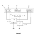
- FIG 3 represents an antenna arrangement according to prior art.
- This antenna arrangement comprises an inner group of radiating elements 100 and two outer groups of radiating elements 101, 102.
- Each group of radiating elements 100, 101, 102 comprises a dual-polar radiating element.
- the group of radiating elements 100, 101, 102 are fed through two power division networks 17, associated with the +45° and -45° polarizations respectively.
- the radiating elements 100, 101, 102 are aligned horizontally.
- Each polarization access of the radiating elements 100, 101, 102 is fed through a single power division network 17.
- Two variable phase shifters 15 are connected to the inner group of radiating elements 100 and the power division networks 17. Each phase shifter 15 is associated with a single polarization (-45° or +45°). The beamwidth of the antenna is controlled by the choice of the power division ratio provided by the power division networks 17 and the phase shift provided by the phase shifters 15. It is usual that the two polarizations have the same beamwidth and the two phase shifters 15 are varied identically.
- the two power division networks 17 comprise three branches for each of the two radiated polarizations.
- This configuration provides a complex and costly antenna with separate power division networks and phase shifters associated with each polarization.
- the polarization characteristics of the outer groups of radiating elements 101, 102 are not critical.
- the antenna comprises a set of radiating elements 30 aligned horizontally.
- the antenna can comprise several sets of radiating elements 30.
- Each set of radiating elements 30 includes an inner group of radiating elements 100 and two outer groups of radiating elements 101, 102.
- the inner group of radiating elements 100 is a central group of radiating elements 100.
- the inner group of radiating elements 100 comprises radiating elements capable of radiating and/or receiving two nominally orthogonally polarized signals.
- Nominally means that the signals have planes of polarization inclined nominally ⁇ 45 degrees relative to the vertical plane.
- the two nominally orthogonally polarized signals can be linear, circular or elliptical.
- the signals can be nominally vertically polarized signals, nominally horizontally polarized signals or nominally circularly polarized signals.
- the outer groups of radiating elements 101, 102 comprise radiating elements capable of radiating and/or receiving signals with a single polarization.
- each of the two outer groups of radiating elements 101, 102 comprises a single radiating element which is a vertically-polarized radiating element laterally disposed relative to the inner group of radiating elements 100.
- the inner group of radiating elements 100 comprises a single dual-polar radiating element.
- This dual-polar radiating element can be a crossed-dipole radiating element or a patch radiating element.
- Each outer group of radiating elements 101, 102 is excited by means of a single power division network 200 with currents of a chosen amplitudes and phases relative to the currents in the dual-polar radiating element of the inner group of radiating elements 100 such that the radiation pattern in the plane containing the groups of radiating elements 100, 101, 102 is modified to provide a chosen 3-dB beamwidth in that plane.
- the inner group of radiating elements 100 comprises at least two input ports 110, 111, each input 110, 111 of the inner group of radiating elements 100 is connected to one output 211, 212 of the power division network 200.
- the dual-polar element of the inner group of radiating elements 100 provides transmission on two orthogonal linear polarizations with polarization planes of +45° and -45° respectively.
- the signals fed to the outer vertically polarized group of radiating elements 101, 102 are required to contain power from both the transmissions made by the inner dual-polar group of radiating elements 100.
- the power division network 200 comprising two inputs 240, 241, each connected to one of the input polarized signals (+45° or -45°).
- the power division network 200 comprises two outputs 221, 222 each connected to one of the vertically polarized outer group of radiating elements 101, 102.
- the signals provided at outputs 221, 222 comprise low level signals derived from both of the inputs 240, 241.
- the antenna can comprise several variable phase shifters 15.
- the antenna comprises two variable phase shifters 15.
- Each variable phase shifter 15 is connected to one of the two input ports 110, 111 of the inner group of radiating elements 100 and to one of the outputs 221, 222 of the power division network 200, allowing adjusting the azimuth beamwidth.
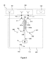
- Figure 5 provides details of a possible embodiment of the invention in which the power division network 200 is a coupling network 230.
- the coupling network 230 comprises two transmission lines 231, 232, each of the transmission lines being connected between one of the input ports 110, 111 of the inner group of radiating elements 100 and one of the input ports 240, 241 of the coupling network 230, respectively.
- the coupling network 230 comprises a coupling line 233 having a portion 233a inductively coupled to a portion 231a, 232a of each of the transmission lines 231, 232 of the coupling network 230.
- the coupling line 233 comprises on one side, a first unconnected end 234 and on the other side, a second end connected to two output lines 112, 113 thereby forming a Tee-junction 235.
- Each output line 112, 113 is connected to one of the outer radiating elements 101, 102 respectively.
- the coupling network 230 can optionally be constructed using any form of radio-frequency transmission line including microstrip lines, striplines or coaxial transmission lines.
- the inner group of radiating elements 100 is a cross polar radiator 100, comprising a crossed dipole, or a dual-polar patch radiating element in which the signals to be radiated with polarizations +45-deg and -45-degrees are connected to one of the two input ports 110, 111 of the inner group of radiating elements 100, respectively.
- the unconnected end 234 of the coupling line 233 can be left open-circuit as shown or can be connected to ground via a resistive terminating load.
- the disposition of the portions 231a, 232a, 233a of the transmission lines 231, 232 and coupling line 233 ensures that a small amount of power from each of portion 231 a, 232a of the transmission lines 231, 232 is coupled to the portion 233a of the coupling line 233 but a negligible amount of power is directly coupled between the transmission lines 231 and 232.
- the coupling between portions of the transmission lines 231, 232 and the coupling line 233 is chosen such that after passing through the Tee junction 235, the power supplying the outer groups of radiating elements 101, 102 is sufficient to provide the chosen radiation pattern from the antenna.
- the total relative lengths of the respective portions of the transmission lines 231, 232 and coupling line 233 are chosen such that the radiating signals in each of the radiating elements have an appropriate phase relationship to create the required radiation pattern from the antenna.
- the phase of the inner groups of radiating elements 100 can be fixed relative to that in the outer groups of radiating elements 101, 102, creating a chosen fixed azimuth beamwidth.
- the azimuth beamwidth can be made variable by the mean of two variable phase shifters 15 connected between the coupling network 230 and the inner group of radiating elements 100. But from the design of this type of coupler 230, it is advantageous to use a unique variable phase shifter 15 within the coupling line 233 and connected to an input end 236 of the portion 233a of coupling line 233 and the Tee junction 235.
- the azimuth beamwidth can be adjusted to a chosen value within the range provided by the configuration.
- the low relative power level required in the outer groups of radiating elements 101, 102 in order to provide a substantial change in the beamwidth compared with that from the single dual-polar radiating element of the inner group of radiating element 100 ensures that the presence of the vertically-polarized outer groups of radiating elements 101, 102 has little effect on the polarization of the signal radiated by the dual-polar radiating element of the inner group of radiating element 100.
- the negligible coupling between the transmission lines 231 and 232 ensures that the isolation between the input ports 241, 242 is very little reduced by the presence of the coupling network 230.
- the performance of the antenna of three radiating elements 100, 101, 102 is very similar to that of an antenna comprising only an isolated dual-polar radiating element, but the composite beamwidth is modified.
- the performance of the configuration shown in Figure 5, according to the invention is very close to that provided by the more complex arrangement shown in Figure 3, according to cited prior art, but its cost is reduced and its reliability is increased.
- the beamwidths achievable by the means described, according to the invention range from 65° to 100° according to the choice of complex coupling coefficients between the transmission lines 231, 232 and the coupling line 233.
- the antenna arrangement has essentially constant performance over a wide operating frequency band, for example, between 1710 and 2170MHz as shown in Figures 6a and 6b.
- Figures 6a and 6b illustrate the adjustable azimuth half-power (3db) beamwidth, in the horizontal plane, of an arrangement as described according to the invention and cited prior art, over the frequency band 1710 - 2170MHz and for the minimum 3 ( Figures 6a) and maximum 4 ( Figures 6b) beamwidths available from a realisation.
- the azimuth half-power (3db) beamwidth 3, 4 can be adjusted when varying the phase with the phase shifter 15.
- the antenna can comprise no phase shifter. In this case, the azimuth half-power (3db) beamwidth can not be adjusted.
- the above description of the invention relates to the simplest realisation in which a single dual-polar radiating element is associated with two outer radiating elements laterally disposed relative to the direction of maximum radiation.
- the inner group of radiating elements 100 and the outer group of radiating elements 101, 102 can comprise several radiating elements.
- the dual-polar antenna comprises a plurality of set of radiating elements 30 aligned in the vertical plane, forming an antenna array.
- This antenna array comprises n radiating elements wide in the horizontal plane (where n has a typical value of 3) and m sets of radiating elements 30 in the vertical plane where m has a value chosen according to the total gain required from the antenna, typically between 4 and 16 sets of radiating elements 30.
- This antenna array comprises m coupling networks 230 connected to each of the m sets of radiating elements 30.
- Each set of radiating elements 30 could be set to the same azimuth beamwidth value. To vary the azimuth beamwidth of this antenna, it is possible, in a particular embodiment, to couple all the phase shifters 15 together and simultaneously. It is possible to actuate them manually or remotely from the antenna.
- Each variable phase shifter 15 can comprise a control device.
- Each control device is connected to a bus.
- the bus is linked to a central unit from where signals corresponding to a selected azimuth beamwidth are transmitted to each variable phase shifter 15.
- the azimuth beamwidth can be controlled with the central unit wherein selected azimuth beamwidth are stored. It can be controlled remotely from the antenna.
- variable phase shifters 15 could receive commands from a data communication means provided by wire transmission or wireless transmission in order to remotely change the azimuth beamwidth of the antenna from a location far from the antenna.
- the radiation patterns, beamwidths, gains and efficiency of the antenna are identical whether it is transmitting or/and receiving a radio signal.
- the example of a transmitting antenna is used and it is to be understood that in accordance with the said Principle of Reciprocity all aspects of the operation and performance of the arrangement can correspondingly be described in terms of a receiving antenna.
Abstract
Description
- The invention concerns a dual-polar antenna for base station of mobile radio systems with adjustable azimuth beamwidth.
- Base stations are typically equipped with several transmit-receive antennas which cover sectors of terrain surrounding the base station. An important consideration in determining the necessary capacity of a base station is the number and angular width of these sectors. It is common for each base station to be equipped with multiple antennas connected to radio transmitters and receivers, each antenna having an azimuth half-power (3dB) beamwidth of between 65 degrees and 90 degrees.
- Many mobile radio system operators provide services which use multiple interface standards and frequency bands, for example using the GSM protocol in the frequency bands 1710 - 1880MHz and the W-CDMA protocol in the band 1900 - 2170MHz. To reduce the cost and physical size of the antenna systems required at each base station it is common for these different radio systems to be served by common antennas. These antennas are required to provide essentially constant operational parameters over the whole frequency band 1710 - 2170MHz, a fractional bandwidth of 26%.
- The capacity of a base station can be less than the theoretical maximum if regularly arranged sectors of coverage are used in locations in which the distribution of users is non-uniform, or in non-uniform land.
- In a system using a code-division multiple access (CDMA) protocol, such as CDMA-2000 or W-CDMA, users whose location lies in the overlap area between adjacent sectors communicate through the radio equipment of all the sectors within whose coverage they lie. While this arrangement provides highly reliable service it also results in a single user consuming radio resources in more than one sector, which can relate to the same or different base stations.
- In these circumstances it is advantageous to be able to remotely adjust the angular width of the sectors of coverage, a parameter primarily determined by the azimuth beamwidth of the antennas serving the appropriate sectors.
- Mobile radio base stations are often equipped with antennas providing for the transmission and reception of two separate radio signals, each signal being linearly polarized and having planes of polarization inclined nominally ± 45 degrees relative to the vertical plane. Such signals are polarized mutually at right angles and their use facilitates the achievement of polarization diversity ("Polarization diversity antennas for compact base stations », Microwave Journal, January 2000, Volume 43, ).
- The transmission or reception of signals with the described polarization requires the use of antenna radiating elements capable of transmitting and receiving signals with these polarizations.
- An antenna array such as described in the cited article would typically be expected to comprise an alignment of identical radiating elements.
- Figures 1 and 2 of the present application are representative of antennas.
- Figure 1 shows configuration of a base station antenna, in which a single vertical column comprising between 4 and 16
radiating elements 1 in the vertical plane is mounted in front of aconductive surface 2 which acts as a reflector, creating a unidirectional beam in the direction of thearrow 3 typically in or close to the horizontal plane. - Figure 2 shows a configuration of a base station antenna comprising multiple vertical columns of radiating elements.
- Each of the
radiating elements 1 comprises a crossed dipole, patch or other configuration chosen to provide the required characteristics of azimuth beamwidth, impedance match and polarization. - It is well known that the azimuth beamwidth of simple radiating elements including patches and crossed-dipoles can be modified by the use of a suitably shaped reflecting screen behind the elements, the shaping of the edges of the screen, the provision of slots in the edges of the screen, or by the use of slots in additional suitably placed passive parasitic elements. Such parasitic elements radiate by virtue of currents induced in them by the fields created by the nearby actively excited elements of the antenna.
- The extent of control of the radiation pattern by the use of parasitic elements is limited by the frequency bandwidth over which the antenna is required to operate. As the frequency changes the amplitude and phases of the currents in the parasitic elements, the radiation pattern of the driven element combined with its associated parasitic elements changes in consequence.
- The provision of a stable azimuth half-power (3dB) beamwidth wider than about 70 degrees (for example 90 degrees) has been found to be not easily achieved without the use of more complex and expensive configurations of radiating elements.
- A wide, stable and adjustable azimuth beamwidth can be obtained by the use of a plurality of radiating elements in which the relative amplitudes of the signals fed to each element are fixed at a suitable value and the relative phases of the signals are varied. The phase of each radiating element can be adjusted independently.
- In the form previously described, an antenna suitable for use at a mobile radio base station would comprise an array of n radiating elements wide in the horizontal plane (where n has a typical value of 3) and m radiating elements in the vertical plane where m has a value chosen according to the total gain required from the antenna, typically between 4 and 16 radiating elements, as shown in figure 2.
- Each group of n
radiating elements 1 disposed in the horizontal plane is typically identical in configuration. In the case of antennas designed to radiate and receive dual-polarized signals eachradiating element 1 is typically designed to support radiating currents having each of the radiated polarizations. In such an array a full feed network with n x m branches is necessary for each of the two radiated polarizations. - This configuration provides a complex antenna array of identical dual-polar radiating elements together with separate power division networks and phase shifters associated with each polarization.
- It is the objective of the present invention to permit the achievement of a dual-polar antenna having a chosen value of azimuth beamwidth using a simpler and less costly arrangement of radiating elements and feed networks.
- To this end, the invention concerns a dual-polar antenna for base station of mobile radio systems with adjustable azimuth beamwidth comprising:
- at least a set of radiating elements comprising :
- o an inner group of radiating elements having at least two input ports,
- o two outer groups of radiating elements, and
- at least one power division network connected to each group of radiating elements.
- the inner group of radiating elements is comprised of radiating elements capable of radiating and/or receiving two nominally orthogonally polarized signals,
- the outer groups of radiating elements are comprised of radiating elements capable of radiating and/or receiving signals with a single polarization.
- According to various embodiments, the present invention also concerns the characteristics below, considered individually or in all their technical possible combinations:
- the inner group of radiating elements comprises a single dual polar radiating element,
- the dual polar radiating elements are crossed-dipole radiating elements,
- the dual polar radiating elements are patch radiating elements,
- the outer groups of radiating elements comprise each a single radiating element,
- it comprises a single power division network feeding the inner and outer groups of radiating elements, said single power division network comprising :
- o two inputs, one for each of the input polarized signals,
- o two outputs connected to the two input ports of the inner group of radiating elements respectively,
- o two outputs, each connected to one of the outer groups of radiating elements,
- it further comprises two variable phase shifters, each variable phase shifter being connected to one of the two input ports of the inner group of radiating elements and to one of the two outputs of the power division network,
- the power division network is a coupling network comprising :
- o two transmission lines, each of the transmission lines being connected between one of the input ports of the inner group of radiating elements and one of the input ports of the coupling network, respectively,
- o a coupling line having a portion inductively coupled to a portion of each of the transmission lines of the coupling network, said coupling line comprising on one side, a first unconnected end and on the other side, a second end connected to two output lines thereby forming a Tee-junction, each output line being connected to one of the outer radiating elements, respectively,
- the coupling network comprises a single variable phase shifter within the coupling line and connected to an input end of the inductively coupled portion of the coupling line and the Tee junction,
- it comprises m sets of radiating elements aligned in the vertical plane, forming an antenna array,
- each variable phase shifter comprises a control device, the control device of each of the variable phase shifters being connected to a bus linked to a central unit, whereby signals corresponding to a selected azimuth beamwidth are transmitted to each variable phase shifter from the central unit,
- the central unit is linked to a data communication means so that the beamwidth can be remotely controled.
- The description of the invention is illustrated by the following drawings in which:
- Figure 1 represents a configuration of a typical base station antenna, according to prior art, comprising a single vertical column of radiating elements ;
- Figure 2 represents a configuration of a typical base station antenna, according to prior art, comprising n radiating elements in the horizontal plane and m radiating elements in the vertical plane ;
- Figure 3 represents an antenna arrangement of three dual-polar radiating elements aligned horizontally (n=3) according to prior art ;
- Figure 4 represents an antenna arrangement comprising a single inner dual-polar radiating element and two outer radiating elements (n=3), according to the invention ;
- Figure 5 represents details of a coupling network, according to the invention ;
- Figure 6a and 6b represent achievable azimuth radiation patterns, of an horizontal arrangement of radiating elements, according to the invention and prior art ;
- Figure 3 represents an antenna arrangement according to prior art. This antenna arrangement comprises an inner group of radiating
elements 100 and two outer groups of radiatingelements elements elements elements elements power division network 17. - Two
variable phase shifters 15 are connected to the inner group of radiatingelements 100 and the power division networks 17. Eachphase shifter 15 is associated with a single polarization (-45° or +45°). The beamwidth of the antenna is controlled by the choice of the power division ratio provided by the power division networks 17 and the phase shift provided by thephase shifters 15. It is usual that the two polarizations have the same beamwidth and the twophase shifters 15 are varied identically. - It is necessary to excite the two outer groups of radiating
elements elements 100. - The two power division networks 17 comprise three branches for each of the two radiated polarizations.
- This configuration provides a complex and costly antenna with separate power division networks and phase shifters associated with each polarization.
- Because the power transmitted by the two outer groups of radiating
elements elements 100, the polarization characteristics of the outer groups of radiatingelements - According to a possible embodiment of the present invention, as shown in figure 4, the antenna comprises a set of radiating
elements 30 aligned horizontally. The antenna can comprise several sets of radiatingelements 30. - Each set of radiating
elements 30 includes an inner group of radiatingelements 100 and two outer groups of radiatingelements elements 100 is a central group of radiatingelements 100. - The inner group of radiating
elements 100 comprises radiating elements capable of radiating and/or receiving two nominally orthogonally polarized signals. - Nominally means that the signals have planes of polarization inclined nominally ± 45 degrees relative to the vertical plane. The two nominally orthogonally polarized signals can be linear, circular or elliptical.
- The signals can be nominally vertically polarized signals, nominally horizontally polarized signals or nominally circularly polarized signals.
- The outer groups of radiating
elements - In this example, each of the two outer groups of radiating
elements elements 100. - The inner group of radiating
elements 100 comprises a single dual-polar radiating element. This dual-polar radiating element can be a crossed-dipole radiating element or a patch radiating element. - Each outer group of radiating
elements power division network 200 with currents of a chosen amplitudes and phases relative to the currents in the dual-polar radiating element of the inner group of radiatingelements 100 such that the radiation pattern in the plane containing the groups of radiatingelements elements 100 comprises at least twoinput ports input elements 100 is connected to oneoutput power division network 200. - The dual-polar element of the inner group of radiating
elements 100 provides transmission on two orthogonal linear polarizations with polarization planes of +45° and -45° respectively. In order to achieve control of the beamwidth for both polarizations, the signals fed to the outer vertically polarized group of radiatingelements elements 100. - This is achieved by the
power division network 200 comprising twoinputs power division network 200 comprises twooutputs elements outputs inputs - The antenna can comprise several
variable phase shifters 15. - In the figure 4, the antenna comprises two
variable phase shifters 15. Eachvariable phase shifter 15 is connected to one of the twoinput ports elements 100 and to one of theoutputs power division network 200, allowing adjusting the azimuth beamwidth. - There exists many known means by which the functionality of the
power division network 200 could be achieved. - Figure 5 provides details of a possible embodiment of the invention in which the
power division network 200 is acoupling network 230. - The
coupling network 230 comprises twotransmission lines input ports elements 100 and one of theinput ports coupling network 230, respectively. - The
coupling network 230 comprises acoupling line 233 having aportion 233a inductively coupled to aportion transmission lines coupling network 230. Thecoupling line 233 comprises on one side, a firstunconnected end 234 and on the other side, a second end connected to twooutput lines junction 235. Eachoutput line outer radiating elements - The
coupling network 230 can optionally be constructed using any form of radio-frequency transmission line including microstrip lines, striplines or coaxial transmission lines. - In this example, the inner group of radiating
elements 100 is a crosspolar radiator 100, comprising a crossed dipole, or a dual-polar patch radiating element in which the signals to be radiated with polarizations +45-deg and -45-degrees are connected to one of the twoinput ports elements 100, respectively. - Each one of the two RF (Radio Frequency)
input ports coupling network 230 fed one of the +45-deg and -45-deg input ports polar radiator 100, respectively. - The
unconnected end 234 of thecoupling line 233 can be left open-circuit as shown or can be connected to ground via a resistive terminating load. The disposition of theportions transmission lines coupling line 233 ensures that a small amount of power from each ofportion transmission lines portion 233a of thecoupling line 233 but a negligible amount of power is directly coupled between thetransmission lines - The coupling between portions of the
transmission lines coupling line 233 is chosen such that after passing through theTee junction 235, the power supplying the outer groups of radiatingelements transmission lines coupling line 233 are chosen such that the radiating signals in each of the radiating elements have an appropriate phase relationship to create the required radiation pattern from the antenna. - The phase of the inner groups of radiating
elements 100 can be fixed relative to that in the outer groups of radiatingelements - In one embodiment, the azimuth beamwidth can be made variable by the mean of two
variable phase shifters 15 connected between thecoupling network 230 and the inner group of radiatingelements 100. But from the design of this type ofcoupler 230, it is advantageous to use a uniquevariable phase shifter 15 within thecoupling line 233 and connected to aninput end 236 of theportion 233a ofcoupling line 233 and theTee junction 235. The azimuth beamwidth can be adjusted to a chosen value within the range provided by the configuration. - The low relative power level required in the outer groups of radiating
elements element 100 ensures that the presence of the vertically-polarized outer groups of radiatingelements element 100. - The negligible coupling between the
transmission lines input ports 241, 242 is very little reduced by the presence of thecoupling network 230. - In these respects the performance of the antenna of three radiating
elements - The beamwidths achievable by the means described, according to the invention, range from 65° to 100° according to the choice of complex coupling coefficients between the
transmission lines coupling line 233. - The antenna arrangement has essentially constant performance over a wide operating frequency band, for example, between 1710 and 2170MHz as shown in Figures 6a and 6b.
- Figures 6a and 6b illustrate the adjustable azimuth half-power (3db) beamwidth, in the horizontal plane, of an arrangement as described according to the invention and cited prior art, over the frequency band 1710 - 2170MHz and for the minimum 3 (Figures 6a) and maximum 4 (Figures 6b) beamwidths available from a realisation.
- The azimuth half-power (3db)
beamwidth phase shifter 15. - In an other embodiment, the antenna can comprise no phase shifter. In this case, the azimuth half-power (3db) beamwidth can not be adjusted.
- The above description of the invention relates to the simplest realisation in which a single dual-polar radiating element is associated with two outer radiating elements laterally disposed relative to the direction of maximum radiation.
- It will be understood by those skilled in the art that this is a particular embodiment and that the method is of general application although the extent of variation in azimuth beamwidth available from arrays with larger number of radiating elements is less then that for the case described.
- The inner group of radiating
elements 100 and the outer group of radiatingelements - In a further embodiment, the dual-polar antenna comprises a plurality of set of radiating
elements 30 aligned in the vertical plane, forming an antenna array. - This antenna array comprises n radiating elements wide in the horizontal plane (where n has a typical value of 3) and m sets of radiating
elements 30 in the vertical plane where m has a value chosen according to the total gain required from the antenna, typically between 4 and 16 sets of radiatingelements 30. - This antenna array comprises
m coupling networks 230 connected to each of the m sets of radiatingelements 30. - Each set of radiating
elements 30 could be set to the same azimuth beamwidth value. To vary the azimuth beamwidth of this antenna, it is possible, in a particular embodiment, to couple all thephase shifters 15 together and simultaneously. It is possible to actuate them manually or remotely from the antenna. - Each
variable phase shifter 15 can comprise a control device. Each control device is connected to a bus. The bus is linked to a central unit from where signals corresponding to a selected azimuth beamwidth are transmitted to eachvariable phase shifter 15. The azimuth beamwidth can be controlled with the central unit wherein selected azimuth beamwidth are stored. It can be controlled remotely from the antenna. - Whatever the way the
variable phase shifters 15 are actuated, the control device could receive commands from a data communication means provided by wire transmission or wireless transmission in order to remotely change the azimuth beamwidth of the antenna from a location far from the antenna. - According to the Principle of Reciprocity it is well established that the performance characteristics of a passive antenna system, that is one not containing amplifiers or non-linear circuit elements, are the same whether the antenna is used for transmission or reception (for example see "Antennas for all applications", JD Kraus & RJ Marhefka, McGraw-Hill, 3rd edition 2002, p 439).
- Specifically the radiation patterns, beamwidths, gains and efficiency of the antenna are identical whether it is transmitting or/and receiving a radio signal. In the above description, to avoid the necessity of describing each component of the antenna system when operating both as a transmitting and as a receiving antenna, the example of a transmitting antenna is used and it is to be understood that in accordance with the said Principle of Reciprocity all aspects of the operation and performance of the arrangement can correspondingly be described in terms of a receiving antenna.
- By using a simpler and less costly arrangement of radiating elements and feed networks, one obtain a dual-polar antenna with performance which is in all operational respects equivalent to that which would be provided by the more complex antenna array of identical dual-polar elements together with separate power division networks and phase shifters associated with each polarization.
Claims (12)
- A dual-polar antenna for a base station of mobile radio systems with adjustable azimuth beamwidth comprising :- at least a set of radiating elements (30) comprising :o an inner group of radiating elements (100) having at least two input ports (110, 111), ando two outer groups of radiating elements (101, 102), and- at least one power division network (17, 200) connected to each group of radiating elements (100, 101, 102),characterised in that :- the inner group of radiating elements (100) is comprised of radiating elements capable of radiating and/or receiving two nominally orthogonally polarized signals,- the outer groups of radiating elements (101, 102) are comprised of radiating elements capable of radiating and/or receiving signals with a single polarization.
- A dual-polar antenna according to claim 1, characterised in that the inner group of radiating elements (100) comprises a single dual polar radiating element.
- A dual-polar antenna according to claim 1 or 2 characterised in that the dual polar radiating elements are crossed-dipole radiating elements.
- A dual-polar antenna according to claim 1 or 2, characterised in that the dual polar radiating elements are patch radiating elements.
- A dual-polar antenna according to anyone of claims 1 to 4, characterised in that the outer groups of radiating elements (101, 102) comprise each a single radiating element.
- A dual-polar antenna according to anyone of claims 1 to 5, characterised in that it comprises a single power division network (200) feeding the inner (100) and outer (101, 102) groups of radiating elements, said single power division network (200) comprising :- two inputs (240, 241), one for each of the input polarized signals,- two outputs (211, 212) connected to the two input ports (110, 111) of the inner group of radiating elements (100) respectively,- two outputs (221, 222), each connected to one of the outer groups of radiating elements (101, 102).
- A dual-polar antenna according to claim 6, characterised in that it further comprises two variable phase shifters (15), each variable phase shifter (15) being connected to one of the two input ports (110, 111) of the inner group of radiating elements (100) and to one of the two outputs (211, 212) of the power division network (200).
- A dual-polar antenna according to claim 6, characterised in that the power division network (200) is a coupling network (230) comprising :- two transmission lines (231, 232), each of the transmission lines being connected between one of the input ports (110, 111) of the inner group of radiating elements (100) and one of the input ports (240, 241) of the coupling network (230), respectively,- a coupling line (233) having a portion (233a) inductively coupled to a portion (231 a, 232a) of each of the transmission lines (231, 232) of the coupling network (230), said coupling line (233) comprising on one side, a first unconnected end (234) and on the other side, a second end connected to two output lines (112, 113) thereby forming a Tee-junction (235), each output line (112, 113) being connected to one of the outer radiating elements (101, 102), respectively.
- A dual-polar antenna according to claim 8, characterised in that the coupling network (230) comprises a single variable phase shifter (15) within the coupling line (233) and connected to an input end (236) of the inductively coupled portion (233a) of the coupling line (233) and the Tee junction (235).
- A dual-polar antenna according to anyone of claims 1 to 9, characterised in that it comprises m sets of radiating elements (30) aligned in the vertical plane, forming an antenna array.
- A dual-polar antenna according to claim 10 as depending upon anyone of claims 7 to 9, characterised in that each variable phase shifter (15) comprises a control device, the control device of each of the variable phase shifters (15) being connected to a bus linked to a central unit, whereby signals corresponding to a selected azimuth beamwidth are transmitted to each variable phase shifter (15) from the central unit.
- A dual-polar antenna according to claim 11, characterised in that the central unit is linked to a data communication means so that the beamwidth can be remotely controled.
Priority Applications (3)
| Application Number | Priority Date | Filing Date | Title |
|---|---|---|---|
| EP20060300564 EP1865576B1 (en) | 2006-06-07 | 2006-06-07 | A dual-polar antenna for a base station of mobile radio systems with adjustable azimuth beamwidth |
| ES06300564.9T ES2544564T3 (en) | 2006-06-07 | 2006-06-07 | Dual polarization antenna for a base station of mobile radiocommunication systems with adjustable azimuth beam width |
| PCT/EP2007/055538 WO2007141281A1 (en) | 2006-06-07 | 2007-06-05 | A dual-polar antenna for a base station of mobile radio systems with adjustable azimuth beamwidth |
Applications Claiming Priority (1)
| Application Number | Priority Date | Filing Date | Title |
|---|---|---|---|
| EP20060300564 EP1865576B1 (en) | 2006-06-07 | 2006-06-07 | A dual-polar antenna for a base station of mobile radio systems with adjustable azimuth beamwidth |
Publications (2)
| Publication Number | Publication Date |
|---|---|
| EP1865576A1 true EP1865576A1 (en) | 2007-12-12 |
| EP1865576B1 EP1865576B1 (en) | 2015-05-06 |
Family
ID=37103253
Family Applications (1)
| Application Number | Title | Priority Date | Filing Date |
|---|---|---|---|
| EP20060300564 Expired - Fee Related EP1865576B1 (en) | 2006-06-07 | 2006-06-07 | A dual-polar antenna for a base station of mobile radio systems with adjustable azimuth beamwidth |
Country Status (3)
| Country | Link |
|---|---|
| EP (1) | EP1865576B1 (en) |
| ES (1) | ES2544564T3 (en) |
| WO (1) | WO2007141281A1 (en) |
Cited By (2)
| Publication number | Priority date | Publication date | Assignee | Title |
|---|---|---|---|---|
| CN107112640A (en) * | 2014-12-29 | 2017-08-29 | 华为技术有限公司 | Honeycomb array with controllable spotlight wave beam |
| CN109861007A (en) * | 2019-01-02 | 2019-06-07 | 武汉虹信通信技术有限责任公司 | A kind of Bipolarization antenna for base station array |
Citations (4)
| Publication number | Priority date | Publication date | Assignee | Title |
|---|---|---|---|---|
| US5629713A (en) * | 1995-05-17 | 1997-05-13 | Allen Telecom Group, Inc. | Horizontally polarized antenna array having extended E-plane beam width and method for accomplishing beam width extension |
| EP1148582A2 (en) * | 2000-04-06 | 2001-10-24 | Lucent Technologies Inc. | Method of producing desired beam widths for antennas and antenna arrays in single or dual polarization |
| WO2002005383A1 (en) * | 2000-07-10 | 2002-01-17 | Andrew Corporation | Cellular antenna |
| WO2003034547A1 (en) * | 2001-10-11 | 2003-04-24 | Kathrein-Werke Kg | Dual-polarization antenna array |
-
2006
- 2006-06-07 ES ES06300564.9T patent/ES2544564T3/en active Active
- 2006-06-07 EP EP20060300564 patent/EP1865576B1/en not_active Expired - Fee Related
-
2007
- 2007-06-05 WO PCT/EP2007/055538 patent/WO2007141281A1/en active Application Filing
Patent Citations (4)
| Publication number | Priority date | Publication date | Assignee | Title |
|---|---|---|---|---|
| US5629713A (en) * | 1995-05-17 | 1997-05-13 | Allen Telecom Group, Inc. | Horizontally polarized antenna array having extended E-plane beam width and method for accomplishing beam width extension |
| EP1148582A2 (en) * | 2000-04-06 | 2001-10-24 | Lucent Technologies Inc. | Method of producing desired beam widths for antennas and antenna arrays in single or dual polarization |
| WO2002005383A1 (en) * | 2000-07-10 | 2002-01-17 | Andrew Corporation | Cellular antenna |
| WO2003034547A1 (en) * | 2001-10-11 | 2003-04-24 | Kathrein-Werke Kg | Dual-polarization antenna array |
Cited By (4)
| Publication number | Priority date | Publication date | Assignee | Title |
|---|---|---|---|---|
| CN107112640A (en) * | 2014-12-29 | 2017-08-29 | 华为技术有限公司 | Honeycomb array with controllable spotlight wave beam |
| EP3227965A4 (en) * | 2014-12-29 | 2018-01-17 | Huawei Technologies Co., Ltd. | Cellular array with steerable spotlight beams |
| CN109861007A (en) * | 2019-01-02 | 2019-06-07 | 武汉虹信通信技术有限责任公司 | A kind of Bipolarization antenna for base station array |
| CN109861007B (en) * | 2019-01-02 | 2021-10-15 | 武汉虹信科技发展有限责任公司 | Dual-polarization base station antenna array |
Also Published As
| Publication number | Publication date |
|---|---|
| WO2007141281A1 (en) | 2007-12-13 |
| EP1865576B1 (en) | 2015-05-06 |
| ES2544564T3 (en) | 2015-09-01 |
Similar Documents
| Publication | Publication Date | Title |
|---|---|---|
| US11283165B2 (en) | Antenna arrays having shared radiating elements that exhibit reduced azimuth beamwidth and increased isolation | |
| US11689263B2 (en) | Small cell beam-forming antennas | |
| GB2523201A (en) | Broadband antenna, multiband antenna unit and antenna array | |
| US20180145400A1 (en) | Antenna | |
| US11677139B2 (en) | Base station antennas having arrays of radiating elements with 4 ports without usage of diplexers | |
| US11962072B2 (en) | Phased array antennas having switched elevation beamwidths and related methods | |
| US10840607B2 (en) | Cellular communication systems having antenna arrays therein with enhanced half power beam width (HPBW) control | |
| US11411301B2 (en) | Compact multiband feed for small cell base station antennas | |
| US10680346B2 (en) | Antenna system with frequency dependent power distribution to radiating elements | |
| US11283160B2 (en) | Base station antennas having arrays with frequency selective shared radiating elements | |
| CN101080848B (en) | Directed dipole antenna | |
| EP1865576B1 (en) | A dual-polar antenna for a base station of mobile radio systems with adjustable azimuth beamwidth | |
| Perruisseau-Carrier et al. | Implementation of a reconfigurable parasitic antenna for beam-space BPSK transmissions | |
| Malviya et al. | MIMO antenna design with low ECC for mmWave | |
| US20230178888A1 (en) | Low-loss switchable panel antennas | |
| WO2023155055A1 (en) | Base station antennas having radiating elements with active and/or cloaked directors for increased directivity | |
| Huang | Antenna Array Designs For Directional Wireless Communicatoin | |
| CN115917879A (en) | Antenna device with improved radiation directivity | |
| MXPA99002531A (en) | Antenna system for enhancing the coverage area, range and reliability of wireless base stations |
Legal Events
| Date | Code | Title | Description |
|---|---|---|---|
| PUAI | Public reference made under article 153(3) epc to a published international application that has entered the european phase |
Free format text: ORIGINAL CODE: 0009012 |
|
| AK | Designated contracting states |
Kind code of ref document: A1 Designated state(s): AT BE BG CH CY CZ DE DK EE ES FI FR GB GR HU IE IS IT LI LT LU LV MC NL PL PT RO SE SI SK TR |
|
| AX | Request for extension of the european patent |
Extension state: AL BA HR MK YU |
|
| 17P | Request for examination filed |
Effective date: 20080612 |
|
| AKX | Designation fees paid |
Designated state(s): DE ES FR GB SE |
|
| 17Q | First examination report despatched |
Effective date: 20100224 |
|
| GRAP | Despatch of communication of intention to grant a patent |
Free format text: ORIGINAL CODE: EPIDOSNIGR1 |
|
| INTG | Intention to grant announced |
Effective date: 20141009 |
|
| GRAS | Grant fee paid |
Free format text: ORIGINAL CODE: EPIDOSNIGR3 |
|
| GRAP | Despatch of communication of intention to grant a patent |
Free format text: ORIGINAL CODE: EPIDOSNIGR1 |
|
| INTG | Intention to grant announced |
Effective date: 20150306 |
|
| GRAA | (expected) grant |
Free format text: ORIGINAL CODE: 0009210 |
|
| AK | Designated contracting states |
Kind code of ref document: B1 Designated state(s): DE ES FR GB SE |
|
| REG | Reference to a national code |
Ref country code: GB Ref legal event code: FG4D |
|
| REG | Reference to a national code |
Ref country code: DE Ref legal event code: R096 Ref document number: 602006045352 Country of ref document: DE Effective date: 20150618 |
|
| REG | Reference to a national code |
Ref country code: SE Ref legal event code: TRGR |
|
| REG | Reference to a national code |
Ref country code: ES Ref legal event code: FG2A Ref document number: 2544564 Country of ref document: ES Kind code of ref document: T3 Effective date: 20150901 |
|
| REG | Reference to a national code |
Ref country code: DE Ref legal event code: R097 Ref document number: 602006045352 Country of ref document: DE |
|
| PLBE | No opposition filed within time limit |
Free format text: ORIGINAL CODE: 0009261 |
|
| STAA | Information on the status of an ep patent application or granted ep patent |
Free format text: STATUS: NO OPPOSITION FILED WITHIN TIME LIMIT |
|
| 26N | No opposition filed |
Effective date: 20160209 |
|
| REG | Reference to a national code |
Ref country code: FR Ref legal event code: PLFP Year of fee payment: 11 |
|
| REG | Reference to a national code |
Ref country code: FR Ref legal event code: PLFP Year of fee payment: 12 |
|
| REG | Reference to a national code |
Ref country code: FR Ref legal event code: PLFP Year of fee payment: 13 |
|
| PGFP | Annual fee paid to national office [announced via postgrant information from national office to epo] |
Ref country code: DE Payment date: 20180608 Year of fee payment: 13 |
|
| PGFP | Annual fee paid to national office [announced via postgrant information from national office to epo] |
Ref country code: FR Payment date: 20180516 Year of fee payment: 13 |
|
| PGFP | Annual fee paid to national office [announced via postgrant information from national office to epo] |
Ref country code: SE Payment date: 20180608 Year of fee payment: 13 |
|
| PGFP | Annual fee paid to national office [announced via postgrant information from national office to epo] |
Ref country code: GB Payment date: 20180403 Year of fee payment: 13 |
|
| REG | Reference to a national code |
Ref country code: DE Ref legal event code: R119 Ref document number: 602006045352 Country of ref document: DE |
|
| REG | Reference to a national code |
Ref country code: SE Ref legal event code: EUG |
|
| PG25 | Lapsed in a contracting state [announced via postgrant information from national office to epo] |
Ref country code: SE Free format text: LAPSE BECAUSE OF NON-PAYMENT OF DUE FEES Effective date: 20190608 |
|
| GBPC | Gb: european patent ceased through non-payment of renewal fee |
Effective date: 20190607 |
|
| PG25 | Lapsed in a contracting state [announced via postgrant information from national office to epo] |
Ref country code: GB Free format text: LAPSE BECAUSE OF NON-PAYMENT OF DUE FEES Effective date: 20190607 Ref country code: DE Free format text: LAPSE BECAUSE OF NON-PAYMENT OF DUE FEES Effective date: 20200101 |
|
| PG25 | Lapsed in a contracting state [announced via postgrant information from national office to epo] |
Ref country code: FR Free format text: LAPSE BECAUSE OF NON-PAYMENT OF DUE FEES Effective date: 20190630 |
|
| PGFP | Annual fee paid to national office [announced via postgrant information from national office to epo] |
Ref country code: ES Payment date: 20200601 Year of fee payment: 14 |
|
| REG | Reference to a national code |
Ref country code: ES Ref legal event code: FD2A Effective date: 20211027 |
|
| PG25 | Lapsed in a contracting state [announced via postgrant information from national office to epo] |
Ref country code: ES Free format text: LAPSE BECAUSE OF NON-PAYMENT OF DUE FEES Effective date: 20200608 |
|
| P01 | Opt-out of the competence of the unified patent court (upc) registered |
Effective date: 20230601 |