EP1865504A1 - Optical pickup device - Google Patents
Optical pickup device Download PDFInfo
- Publication number
- EP1865504A1 EP1865504A1 EP07011151A EP07011151A EP1865504A1 EP 1865504 A1 EP1865504 A1 EP 1865504A1 EP 07011151 A EP07011151 A EP 07011151A EP 07011151 A EP07011151 A EP 07011151A EP 1865504 A1 EP1865504 A1 EP 1865504A1
- Authority
- EP
- European Patent Office
- Prior art keywords
- spherical aberration
- coupling lens
- pickup device
- initial position
- optical pickup
- Prior art date
- Legal status (The legal status is an assumption and is not a legal conclusion. Google has not performed a legal analysis and makes no representation as to the accuracy of the status listed.)
- Withdrawn
Links
- 230000003287 optical effect Effects 0.000 title claims abstract description 198
- 230000004075 alteration Effects 0.000 claims abstract description 202
- 230000008878 coupling Effects 0.000 claims abstract description 201
- 238000010168 coupling process Methods 0.000 claims abstract description 201
- 238000005859 coupling reaction Methods 0.000 claims abstract description 201
- 230000007246 mechanism Effects 0.000 claims abstract description 21
- 239000012141 concentrate Substances 0.000 claims abstract description 4
- 230000005540 biological transmission Effects 0.000 claims description 24
- 238000001514 detection method Methods 0.000 claims description 20
- 230000000903 blocking effect Effects 0.000 claims description 2
- 239000010410 layer Substances 0.000 description 110
- 238000000034 method Methods 0.000 description 19
- 230000010287 polarization Effects 0.000 description 11
- 230000007274 generation of a signal involved in cell-cell signaling Effects 0.000 description 8
- 239000004065 semiconductor Substances 0.000 description 5
- 230000007613 environmental effect Effects 0.000 description 4
- 239000002356 single layer Substances 0.000 description 4
- 238000004519 manufacturing process Methods 0.000 description 3
- 230000008602 contraction Effects 0.000 description 2
- 238000003780 insertion Methods 0.000 description 2
- 230000037431 insertion Effects 0.000 description 2
- 230000001154 acute effect Effects 0.000 description 1
- 230000007423 decrease Effects 0.000 description 1
- 230000000694 effects Effects 0.000 description 1
- 239000011521 glass Substances 0.000 description 1
- 230000004044 response Effects 0.000 description 1
- 125000006850 spacer group Chemical group 0.000 description 1
- 239000000758 substrate Substances 0.000 description 1
Images




Classifications
-
- G—PHYSICS
- G11—INFORMATION STORAGE
- G11B—INFORMATION STORAGE BASED ON RELATIVE MOVEMENT BETWEEN RECORD CARRIER AND TRANSDUCER
- G11B7/00—Recording or reproducing by optical means, e.g. recording using a thermal beam of optical radiation by modifying optical properties or the physical structure, reproducing using an optical beam at lower power by sensing optical properties; Record carriers therefor
- G11B7/12—Heads, e.g. forming of the optical beam spot or modulation of the optical beam
- G11B7/135—Means for guiding the beam from the source to the record carrier or from the record carrier to the detector
- G11B7/1392—Means for controlling the beam wavefront, e.g. for correction of aberration
- G11B7/13925—Means for controlling the beam wavefront, e.g. for correction of aberration active, e.g. controlled by electrical or mechanical means
- G11B7/13927—Means for controlling the beam wavefront, e.g. for correction of aberration active, e.g. controlled by electrical or mechanical means during transducing, e.g. to correct for variation of the spherical aberration due to disc tilt or irregularities in the cover layer thickness
-
- G—PHYSICS
- G11—INFORMATION STORAGE
- G11B—INFORMATION STORAGE BASED ON RELATIVE MOVEMENT BETWEEN RECORD CARRIER AND TRANSDUCER
- G11B7/00—Recording or reproducing by optical means, e.g. recording using a thermal beam of optical radiation by modifying optical properties or the physical structure, reproducing using an optical beam at lower power by sensing optical properties; Record carriers therefor
- G11B7/12—Heads, e.g. forming of the optical beam spot or modulation of the optical beam
- G11B7/135—Means for guiding the beam from the source to the record carrier or from the record carrier to the detector
- G11B7/1372—Lenses
- G11B7/1376—Collimator lenses
-
- G—PHYSICS
- G11—INFORMATION STORAGE
- G11B—INFORMATION STORAGE BASED ON RELATIVE MOVEMENT BETWEEN RECORD CARRIER AND TRANSDUCER
- G11B7/00—Recording or reproducing by optical means, e.g. recording using a thermal beam of optical radiation by modifying optical properties or the physical structure, reproducing using an optical beam at lower power by sensing optical properties; Record carriers therefor
- G11B2007/0003—Recording, reproducing or erasing systems characterised by the structure or type of the carrier
- G11B2007/0009—Recording, reproducing or erasing systems characterised by the structure or type of the carrier for carriers having data stored in three dimensions, e.g. volume storage
- G11B2007/0013—Recording, reproducing or erasing systems characterised by the structure or type of the carrier for carriers having data stored in three dimensions, e.g. volume storage for carriers having multiple discrete layers
-
- G—PHYSICS
- G11—INFORMATION STORAGE
- G11B—INFORMATION STORAGE BASED ON RELATIVE MOVEMENT BETWEEN RECORD CARRIER AND TRANSDUCER
- G11B7/00—Recording or reproducing by optical means, e.g. recording using a thermal beam of optical radiation by modifying optical properties or the physical structure, reproducing using an optical beam at lower power by sensing optical properties; Record carriers therefor
- G11B7/08—Disposition or mounting of heads or light sources relatively to record carriers
- G11B7/085—Disposition or mounting of heads or light sources relatively to record carriers with provision for moving the light beam into, or out of, its operative position or across tracks, otherwise than during the transducing operation, e.g. for adjustment or preliminary positioning or track change or selection
- G11B7/08505—Methods for track change, selection or preliminary positioning by moving the head
- G11B7/08511—Methods for track change, selection or preliminary positioning by moving the head with focus pull-in only
-
- G—PHYSICS
- G11—INFORMATION STORAGE
- G11B—INFORMATION STORAGE BASED ON RELATIVE MOVEMENT BETWEEN RECORD CARRIER AND TRANSDUCER
- G11B7/00—Recording or reproducing by optical means, e.g. recording using a thermal beam of optical radiation by modifying optical properties or the physical structure, reproducing using an optical beam at lower power by sensing optical properties; Record carriers therefor
- G11B7/08—Disposition or mounting of heads or light sources relatively to record carriers
- G11B7/09—Disposition or mounting of heads or light sources relatively to record carriers with provision for moving the light beam or focus plane for the purpose of maintaining alignment of the light beam relative to the record carrier during transducing operation, e.g. to compensate for surface irregularities of the latter or for track following
- G11B7/0945—Methods for initialising servos, start-up sequences
Definitions
- the present invention relates to an optical pickup device. More specifically, the present invention relates to an optical pickup device which is suitably used in an optical disc device which performs optical recording or reproduction of information to/from an information storage medium such as an optical disc.
- optical pickup devices which perform recording/reproduction to/from optical discs each having optical transmission layers which are different in thickness, such as DVD (Digital Versatile Disc) and CD (Compact disc) ( Japanese Laid-Open Patent Application No. 10-3687 ; published on January 6, 1998).
- the optical pickup recited in the patent document corrects spherical aberration occurring on account of difference in thickness of an optical transmission layer, by adjusting the distance between a laser light source and a coupling lens. That is to say, in the aforesaid optical pickup, the distance between the laser light source and the coupling lens is adjusted by moving the laser light source or the coupling lens by moving means.
- This method of correcting spherical aberration caused by an error in thickness of an optical transmission layer by moving a coupling leans (collimator lens) may also be used for correcting spherical aberration caused by an error in thickness of an optical transmission layer of a multi-layer optical disc.
- a position detection device As means for detecting a position of the movable body in the dive device using the aforesaid piezoelectric element, it is possible to use a position detection device using a magnet and hall elements ( Japanese Laid-Open Patent Application No. 2005-331399 ; published on December 2, 2005).
- the position detection device recited in the patent document is provided with a processing circuit which detects relative positions of a magnet and two hall elements, because the characteristics of the hall elements and magnet significantly changes depending on temperature. To hold the sums of output values of the respective hall elements to be constant, values input to the respective hall elements are controlled and a difference between the output values from the respective hall elements is detected as a position output.
- the optical pickup device recited in this patent document detects a spherical aberration error signal in the following manner: a hologram provided between a light source and an objective lens is divided into an inner part and an outer part, and the spherical aberration error signal is detected based on a difference between an output signal from an optical detector detecting light diffracted at the inner part of the hologram and an output signal from an optical detector detecting light diffracted at the outer part of the hologram. Based on the spherical aberration error signal, spherical aberration is corrected.
- the focusing operation is unstable when focus control is performed to obtain a spherical aberration error signal, in a state that correction of spherical aberration is not properly performed.
- optical disc devices Japanese Laid-Open Patent Application No. 2002-373441 ; published on December 26, 2002
- This patent document recites an optical pickup having aberration correction means which corrects spherical aberration in a collecting optical system.
- This aberration correction means sets a degree of spherical aberration correction in advance, before focus control is carried out.
- the spherical aberration correction is carried out using an aberration correction lens, based on the spherical aberration correction degree thus set.
- a resonance frequency varies in accordance with an environmental temperature, load, or the like, in case where a piezoelectric element is used as the moving means.
- an optimal frequency of a drive signal for the piezoelectric element as the moving means varies in accordance with an environmental temperature, load, or the like.
- a position of a movable body it is necessary to detect a position of a movable body in case where a piezoelectric element is used as the moving means.
- the detection of a position of a movable body can be done using a magnet and hall elements.
- two hall elements are required to detect a position of a movable body because the characteristics of hall elements and a magnet significantly vary in accordance with temperature, and a processing circuit for detecting relative positions of two hall elements is also required. This induces increase in the size and costs of the optical pickup device.
- an optimal position of the movable body with a coupling lens must constantly be changed to correct either a thickness error in an optical transmission layer in a single layer in case of a single-layer optical disc or a thickness error in optical transmission layers that are different layers in case of multi-layer optical disc, in order to correct spherical aberration due to a thickness error in an optical transmission layer.
- a spherical aberration error signal is used to correct the spherical aberration. It seems that a position of the coupling lens is controllable solely by a spherical aberration error signal, but the spherical aberration error signal is obtained only by conducting focus control after properly executing spherical aberration correction.
- a spherical aberration error signal is obtained in such a manner that focus control is performed after the coupling lens is moved so as to allow for spherical aberration correction suitable for a recording surface to which the focus control is performed.
- the drive device of the coupling lens adopting a piezoelectric element may not be able to move the coupling lens to a desired position, because the moving distance is inconsistent on account of variation in the resonance frequency in accordance with an environmental temperature, load, or the like.
- the inconsistency in the moving distance becomes more acute as the distance between the reference position (initial position) of the coupling lens and a desired position increases.
- an optical pickup device which performs recording or reproduction with respect to a double-layer optical disc
- the following arrangement may be used: to perform recording or reproduction with respect to an information recording layer which is the first layer or second layer, a first reference position and a second reference position are set for a coupling lens by which variation of spherical aberration caused by a thickness error in an optical transmission layer of the optical information storage medium is corrected, and photo interrupters are provided at the respective positions.
- the number of photo interrupters increases as the number of the layers of an optical disc increases.
- the size and costs of the optical pickup device also increase.
- the present invention was done to solve the problem above, and the objective of the present invention is to provide an optical pickup device which can stably perform focus control and spherical aberration correction, without increase in the number of photo interrupters.
- the optical pickup device of the present invention includes: a light source; an objective lens which concentrates a light beam from the light source, onto an information recording surface of an optical information storage medium; and a spherical aberration correction mechanism provided on an optical path between the light source and the objective lens, the spherical aberration correction mechanism including: moving means for moving a coupling lens; initial position detection means for detecting whether the coupling lens has been moved to an initial position; and movement control means for moving the coupling lens, which has been moved to the initial position, to one of first position to n-th (n is an integer not less than 2) positions whose distances from the initial position are predetermined, where the light beam is concentrated at an information recording layer of one of first layer to n-th layer of the optical information storage medium.
- the coupling lens can be moved to the initial position and the coupling lens having been moved to the initial position can be detected.
- the coupling lens can be quickly moved to the initial position.
- the coupling lens can be moved from the initial position to a desired position (one of the first to n-th positions).
- a spherical aberration error signal is detected by performing focus control after the coupling lens is moved to either the initial position or the desired position. Spherical aberration is corrected based on the spherical aberration error signal, and hence a recording or reproduction signal is suitably obtained from an optical storage medium.
- the optical pickup device of the present embodiment includes an integrated unit 1, a spherical aberration correction mechanism 10, and an objective lens unit 50.
- the integrated unit 1 includes a semiconductor laser 2 (light source), a light receiving section 3, a light detector (detection means) 4, a spacer 5, a polarization hologram 6, and a glass substrate 7.
- the objective lens unit 50 includes an objective lens 51, an actuator 52, an aperture stop 53, a quarter wave plate 54, and a holder 55.
- the objective lens unit 50 faces an optical disc 45 (information storage medium).
- the objective lens 51, the aperture stop 53, the quarter wave plate 54 are fixed to the holder 55, and these members are driven as a unit, when the objective lens 51 focuses or tracks a target track on a first information recording layer 45b (information recording surface) or a second information recording layer 45c (information recording surface) of the optical disc 45.
- the number of information recording layers in the optical disc 45 is not particularly limited. To simplify, for example, the description of the operation of the optical pickup device, it is assumed that the optical disc 45 has an optical transmission layer 45a and two optical transmission layer, i.e. first and second information recording layers 45b and 45c.
- the spherical aberration correction mechanism 10 includes friction drive axes 11 and 12, a piezoelectric element 13 (moving means), a coupling lens 14, stoppers 15a and 15b, a lens holder 16, a catching section 17, a light shielding plate 18 (shielding plate), a base member 19, a photo interrupter 20 (initial position detection means), and a spherical aberration correction element control circuit 73 (movement control means).
- the spherical aberration correction mechanism 10 is provided between the integrated unit 1 and the objective lens unit. Between the spherical aberration correction mechanism 10 and the objective lens unit 50, a reflecting plate 40 is provided for changing the direction of light. Details of these members will be given below.
- the polarization hologram 6 is an element which selectively allows light to pass through or diffracts light in accordance with the polarization direction.
- the polarization hologram 6 also functions as light branching means for outgoing light and incoming light.
- Linearly polarized light in the X axis direction which is output from the semiconductor laser 2
- the circularly-polarized reflected light from the first information recording layer 45b or the second information recording layer 45c is converted in linearly polarized light in the Y axis direction, by the quarter wave plate 54.
- the reflected light from the first information recording layer 45b or the second information recording layer 45c is linearly polarized light which is in parallel to not the X axis but the Y axis.
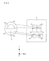
- the linearly polarized light is diffracted by the polarization hologram 6. The following will describe the diffraction of reflected light by the polarization hologram 6, in reference to Fig. 2.
- Fig. 2 outlines the polarization hologram 6.
- the polarization hologram 6 is constituted by four regions 6a-6d.
- the respective regions 6a-6d diffract the reflected light from the optical disc, in different directions.
- four light beams are generated by the polarization hologram 6.
- the light diffracted by the polarization hologram 6 is supplied to the light receiving section 3 of the light detector 4.
- the light receiving section 3 is constituted by light receiving elements 3a-3f, and each light receiving element outputs an output signal in accordance with an amount of received light.
- the spherical aberration error signal SAS is either positive or negative in accordance with an error in thickness of the optical transmission layer, in case where the coupling lens is not at an optimal position.
- Spherical aberration correction is carried out so that a position of the coupling lens is moved in parallel to the optical axis in such a manner as to cause a value of the spherical aberration error signal SAS to be zero.
- one end of the piezoelectric element 13 is fixed to the base member 19, whereas the other end of the piezoelectric element 13 is fixed to the friction drive axis 12.
- the friction drive axis 12 is fixed to the catching section 17.
- the catching section 17 is moved.
- the catching section 17 is connected to the coupling lens 14, with the result that the coupling lens 14 can move with the catching section 17.
- the coupling lens 14 is connected to the lens holder 16. Through the intermediary of the lens holder 16, the coupling lens 14 is in frictional engagement with the friction drive axis 11.
- the respective ends of the friction drive axis 11 are connected with the stoppers 15a and 15b.
- the lens holder 16 can move in the space between the stoppers 15a and 15b.
- the distance from the initial position P0 to the position P1 or P2 is determined in advance.
- P1 and P2 are preferably set at positions where spherical aberration is minimized when recording or reproduction to/from the first information recording surface 45b and the second information recording surface 45c of the double-layer optical disc 45 is carried out.
- P1 is on the objective lens side whereas P2 is on the light source side.
- the position of P0 is not particularly limited as long as P0 is positioned between P1 and P2.
- P0 is preferably positioned at the midway point between P1 and P2.
- the optical pickup device of the present embodiment assumes that recording and reproduction are carried out with respect to the double-layer optical disc 45.
- the number of information recording layers in the optical disc 45 is not particularly limited. In case where the number of information recording layers in the optical disc 45 is three or more, P1 is positioned to be closest to the objective lens whereas Pn is positioned to be closed to the light source. In this case, the initial position P0 is provided between P1 and Pn. P0 is preferably positioned at the midway point between P1 and P2.
- the photo interrupter 20 is provided at P0 (initial position) on the base member 19, the photo interrupter 20 is provided.
- the photo interrupter 20 is constituted by a light emitting element and a light receiving element (not illustrated), and light is fed from the light emitting element to the light receiving element. By checking if the light is blocked or not, it is possible to detect whether a shielding object exists between the light emitting element and the light receiving element. Therefore, in the optical pickup device of the present embodiment, the light emitting element and the light receiving element are provided at P0 and the light shielding plate 18 is provided between these two elements.
- the lens holder 16 is connected to the light shielding plate 18, and the light shielding plate 18 can move with the coupling lens 14. A position of the coupling lens 14 is detected by changing the light receiving state of the photo interrupter 20 by means of the light shielding plate 18.
- the coupling lens 14 is preferably arranged so as to be able to go over P1 or P2, in consideration of the following factors: manufacturing tolerance and erection tolerance of the members constituting the spherical aberration correction mechanism 10, erection tolerance at the time of mounting the spherical aberration correction mechanism 10 to the optical pickup device, an error in thickness of the optical transmission layer 12a from the surface of the double-layer optical disc 45 to the first information recording surface 45b or the second information recording surface 45c of the optical disc 45, deviation of the coupling lens 14 from the position where the spherical aberration is minimized, due to wavelength variation, and the like.
- the stoppers 15a and 15b are provided so that the coupling lens 14 can move in the space between the stoppers 15a and 15b.
- the positions where the coupling lens 14 contacts the respective stoppers 15a and 15b are termed Ea and Eb, respectively.
- the coupling lens 14 moves between Ea and Eb.
- a position of the coupling lens 14 is controlled based on the detection of the initial position by the photo interrupter 20 and a spherical aberration error signal obtained by the light receiving section 3 of the optical pickup device, in order to correct spherical aberration.
- the following will discuss a method of controlling a position of the coupling lens 14 based on the detection of the initial position by the photo interrupter 20 and the spherical aberration error signal obtained by the light receiving section 3 of the optical pickup device.
- a position of the coupling lens 14 must constantly be changed to correct either a thickness error of an optical transmission layer in a single layer in case of a single-layer optical disc or a thickness error of an optical transmission layer on account of different layers in case of multi-layer optical disc.
- a spherical aberration error signal is used for the correction. It seems that a position of the coupling lens is controllable solely by a spherical aberration error signal, but the spherical aberration error signal is obtained only by conducting focus control after properly executing spherical aberration correction.
- a spherical aberration error signal is obtained in such a manner that focus control is performed after the coupling lens is moved so as to allow for spherical aberration correction suitable for a recording surface to which the focus control is performed.
- the coupling lens it is necessary to move the coupling lens to the vicinity of a position where spherical aberration correction is possible, in order to perform spherical aberration correction suitable for a recording surface to which the focus control is carried out.
- the drive device of the coupling lens adopting a piezoelectric element may not be able to move the coupling lens to a desired position, because the moving distance is inconsistent on account of variation in the resonance frequency in accordance with an environmental temperature, load, or the like.
- the drive pulse number for driving the piezoelectric element increases.
- the initial position P0 of the coupling lens 14 preferably locates between P1 and P2.
- P0 locates at the midway point between P1 and P2.
- a spherical aberration error signal can be detected while the coupling lens 14 locates at P0.
- a spherical aberration error signal is detected after the coupling lens 14 is moved from P0 to P1 or P2.
- the coupling lens 14 can be precisely moved to P1 or P2, because distance from P0 to P1 or P2 is short.
- the photo interrupter 20 is arranged such that a light emitting element and a light receiving element, which are not illustrated, are positioned so as to face each other and are packaged as a single member. It is therefore possible to notify, in binary manner, whether a shielding object exists between two elements. For example, as shown in Fig. 3, when the coupling lens 4 is at a position which is away from P0 in the positive direction along the Z axis, the light supplied from the light emitting element to the light receiving element is blocked by the light shielding plate 18.
- the light shielding plate 18 is arranged (i) so as not to block the light emitted from the light emitting element to the light receiving element of the photo interrupter 20, when the coupling lens 14 is away from the initial position P0 in the negative direction along the Z axis, and (ii) so as to block the light emitted from the light emitting element to the light receiving element of the photo interrupter 20, when the coupling lens 14 is away from the initial position P0 in the positive direction along the Z axis.
- the light shielding plate 18 may be arranged (i) so as to block the light emitted from the light emitting element to the light receiving element of the photo interrupter 20, when the coupling lens 14 is away from the initial position P0 in the negative direction along the Z axis, and (ii) so as not to block the light emitted from the light emitting element to the light receiving element of the photo interrupter 20, when the coupling lens 14 is away from the initial position P0 in the positive direction along the Z axis.
- the aforesaid arrangement makes it possible to specify a relative position of the coupling lens 14 with respect to P0, wherever the coupling lens 14 is positioned.
- Non-limiting examples of cases where the coupling lens 14 is moved to P0 include insertion of a new disc, turning on the power, and turning on the power after the system abnormally ends on account of a power failure.
- the coupling lens 14 is uncertain to which direction the coupling lens 14 must be moved to return the same to P0. For example, when at least one of the L level and H level has two types or more, after the coupling lens is moved toward Ea (or Eb) for a sufficient amount of time, the coupling lens is moved toward Eb (or Ea) and the number of rises or falls of the L level and H level is detected. Based on the detected number of rises and falls of the L level and H level, the coupling lens 14 is returned to the initial position P0. In this case a certain amount of time is required to return the coupling lens 14 to the initial position P0.
- the coupling lens 14 can be quickly returned to P0 by adopting the arrangement such that a single type of L level is output when the coupling lens 14 moves from the initial position P0 in the positive direction along the Z axis whereas a signal type of H level is output when the coupling lens 14 moves in the negative direction along the Z axis.
- the photo interrupter is used in the present embodiment, similar effects can be attained when a position sensor whose function is similar to that of the photo interrupter is used.
- a photo reflector which is a reflective photo sensor.
- This photo reflector is constituted by an LED and a light receiving element which are packaged into a single member, and detects if an object exists by applying light from the LED to the object and detecting the return light from the object by the light receiving element.
- the following will describe a method of detecting a spherical aberration error signal and a method of correcting spherical aberration, in regard to the optical pickup device of the present embodiment.
- a spherical aberration error signal is detected while the coupling lens 14 is positioned at P0.
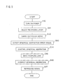
- the following will give details of a method of correction spherical aberration in the optical pickup device of the present embodiment, with reference to Figs. 1, 3, and 5.
- the power is turned on for a start (S10).
- the coupling lens is at the initial position P0.
- P0 locates between P1 and P2.
- a spherical aberration error signal can be detected while the coupling lens is positioned at P0. Therefore, without moving the coupling lens 14 to P1 or P2, a spherical aberration error signal is detected while the coupling lens is positioned at P0.
- an information recording layer of the optical disc is selected (S11).
- the objective lens 51 is moved by the actuator 52 based on the information supplied from a track drive circuit 71 and a focus drive circuit 72, in such a way as to focus the first information recording layer 45b or the second information recording layer 45c of the optical disc 45.
- focus control focus servo
- focus control focus servo
- laser light emitted from the semiconductor laser 2 passes through the coupling lens 14, and then the laser light is collected by the objective lens 51 and applied to the first information recording layer 45b or the second information recording layer 45c.
- the coupling lens 14 is positioned at P0 on this occasion. Since P0 is close to P1 and P2, it is possible to focus on the first information recording layer 45b or the second information recording layer 45c.
- a control signal generation circuit 70 figures out a spherical aberration error signal (S13). How the spherical aberration error signal is figured out is not described here, because it has been explained above.
- spherical aberration control is carried out (S14).
- spherical aberration control spherical aberration caused by a thickness error in an optical transmission layer is corrected by controlling a position of the coupling lens.
- a spherical aberration error signal is used for the control of a position of the coupling lens.
- the spherical aberration error signal is positive or negative in accordance with a thickness error in an optical transmission layer, in case where a position of the coupling lens is not optimal.
- a position of the coupling lens is moved along the optical axis in such a way as to cause the value of the spherical aberration error signal to be zero, so that spherical aberration correction is achieved.
- the coupling lens is moved so that spherical aberration is corrected (S15 and S16).
- the control signal generation circuit 70 determines a position of the coupling lens 14 for correcting the spherical aberration and also determines a voltage to be applied to the piezoelectric element 13 in order to move the coupling lens to the position thus determined.
- the spherical aberration correction element control circuit 73 applies the voltage to the piezoelectric element 13. In accordance with the voltage application to the piezoelectric element 13, the piezoelectric element is deformed so that the coupling lens 14 is moved to the position optimal for correcting the spherical aberration.
- a spherical aberration error signal is detected while the coupling lens 14 is positioned at P0.
- the optical pickup device of the present embodiment performs very simple steps from the turning on the power to signal reproduction. As a result, spherical aberration is quickly corrected.
- a spherical aberration error signal is detected while the coupling lens 14 is positioned at P0.
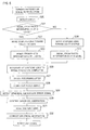
- the optical pickup device of the present embodiment for a start, it is determined if the optical pickup device is in an error state (S20).
- the error state include insertion of a new disc, turning on the power, and turning on the power after the system abnormally ends on account of a power failure.
- the coupling lens 14 is not positioned at P0.
- the level of an output signal of the photo interrupter 20, which is either H level or L level, is detected (S21). With this, a relative position of the coupling lens 14 with respect to the photo interrupter 20 is detected. For example, when the output signal is at H level, the coupling lens 14 is positioned on the P2 side. On the other hand, when the output signal is at L level, the coupling lens 14 is on the P1 side (see Figs. 3 and 4, for example).
- the coupling lens 14 When the output signal is at H level, the coupling lens 14 is moved toward P1 (toward the objective lens) (S22). The movement of the coupling lens 14 is stopped when the photo interrupter 20 detects L level (S23). As a result, the coupling lens 14 is positioned at P0 (S26). In the meanwhile, when the output signal is at L level, the coupling lens 14 is moved toward P2 (toward the light source) (S24). The movement of the coupling lens 14 is stopped when the photo interrupter 20 detects H level (S25). As a result, the coupling lens 14 is positioned at P0 (S26).
- the optical pickup device of the present embodiment it is possible to detect a relative position of the coupling lens 14 with respect to the photo interrupter 20, by means of an output signal of the photo interrupter 20.
- the coupling lens 14 can be returned to the initial position P0 by moving the coupling lens 14 once. It is therefore possible to reduce a time required for returning the coupling lens 14 to the initial position P0.
- P0 locates between P1 and P2.
- the coupling lens 14 positioned at P0 can detect a spherical aberration error signal. In this way, in the optical pickup device of the present embodiment, the coupling lens positioned at P0 detects a spherical aberration error signal, without being moved to P1 or P2.
- an information recording layer of the optical disc to which the latter-stage focus control is carried out, is selected (S27).
- the actuator 52 moves the objective lens 51 based on information supplied from the track drive circuit 71 and the focus drive circuit 72, in such a way as to cause the objective lens 51 to focus either the first information recording layer 45b or the second information recording layer 45c of the optical disc 45.
- focus control focus servo
- S28 focus control
- laser light emitted from the semiconductor laser 2 passes through the coupling lens 14, and then the laser light is collected by the objective lens 51 and applied to the first information recording layer 45b or the second information recording layer 45c.
- the coupling lens 14 is positioned at P0. Since P0 is close to P1 and P2, the coupling lens 14 can focus the first information recording layer 45b or the second information recording layer 45c.
- the control signal generation circuit 70 figures out a spherical aberration error signal (S29). How the spherical aberration error signal is figured out is not described here, because it has been explained above.
- the spherical aberration is a method of correcting, by controlling a position of the coupling lens, spherical aberration caused by a thickness error in an optical transmission layer.
- a spherical aberration error signal is particularly used for controlling a position of the coupling lens.
- a spherical aberration signal is positive or negative in accordance with a thickness error in the optical transmission layer, in case where the coupling lens is not at an optimal position.
- a position of the coupling lens is moved along the optical axis in such a way as to cause the value of the spherical aberration error signal to be zero, so that spherical aberration correction is achieved.
- the coupling lens is moved so that spherical aberration is corrected (S31 and S32).
- a position of the coupling lens 14 is determined based on the calculated spherical aberration error signal in order to correct the spherical aberration, and a voltage to be applied to the piezoelectric element 13 in order to move the coupling lens 14 to the position thus determined is also determined.
- the spherical aberration correction element control circuit 73 applies the voltage to the piezoelectric element 13. In accordance with the applied voltage, the piezoelectric element 13 deforms so that the coupling lens 14 is moved to the position optimal to the correction of the spherical aberration.
- the optical pickup device of the present embodiment it is possible to quickly return the coupling lens 14 to the initial position P0, wherever the coupling lens 14 is positioned. Then a spherical aberration error signal is detected so that spherical aberration is quickly corrected.
- a spherical aberration error signal is detected while the coupling lens 14 is positioned at P1 or P2.
- the coupling lens is positioned at the initial position P0.
- the initial position P0 locates between P1 and P2. Since in this case the initial position P0 is close to P1 and P2 which are suitable for the recording surface to which focus control is carried out, the coupling lens 14 can be quickly moved to P1 or P2. Therefore, in the optical pickup device of the present embodiment, a spherical aberration error signal is detected after the coupling lens 14 is moved to P1 or P2.
- an information recording layer of the optical disc is selected (S41).
- the actuator 52 moves the objective lens 51 based on information from the track drive circuit 71 and the focus drive circuit 72, in such a manner as to cause the objective lens 51 to focus either the first information recording layer 45b or the second information recording layer 45c of the optical disc 45.
- the coupling lens 14 is moved to P1 or P2 (S42).
- the coupling lens 14 is moved to P1.
- the coupling lens 14 is moved to P2.
- the information in regard to the relative position of P0 with respect to P1 and P2 and the information in regard to a voltage applied to the piezoelectric element 13 in order to move the coupling lens 14 to P1 or P2 are stored in the control signal generation circuit 70.
- the spherical aberration correction element control circuit 73 applies a voltage to the piezoelectric element 13. In accordance with the applied voltage, the piezoelectric element deforms, with the result that the coupling lens 14 is moved to P1 or P2.
- focus control focus servo
- focus control focus servo
- laser light emitted from the semiconductor laser 2 passes through the coupling lens 14, and then the laser light is collected by the objective lens 51 and applied to the first information recording layer 45b or the second information recording layer 45c.
- the coupling lens 14 since the coupling lens 14 on this occasion is positioned at P1 or P2, the coupling lens 14 can focus the first information recording layer 45b or the second information recording layer 45c.
- the control signal generation circuit 70 figures out a spherical aberration error signal (S44). How the spherical aberration error signal is figured out is not described here, because it has been explained above.
- the spherical aberration is a method of correcting, by controlling a position of the coupling lens, spherical aberration caused by a thickness error in an optical transmission layer.
- a spherical aberration error signal is particularly used for controlling a position of the coupling lens.
- a spherical aberration signal is positive or negative in accordance with a thickness error in the optical transmission layer, in case where the coupling lens is not at an optimal position.
- a position of the coupling lens is moved along the optical axis in such a way as to cause the value of the spherical aberration error signal to be zero, so that spherical aberration correction is achieved.
- the coupling lens is moved so that spherical aberration is corrected (S46 and S47).
- a position of the coupling lens 14 is determined based on the calculated spherical aberration error signal in order to correct the spherical aberration, and a voltage to be applied to the piezoelectric element 13 in order to move the coupling lens 14 to the position thus determined is also determined.
- the spherical aberration correction element control circuit 73 applies the voltage to the piezoelectric element 13. In accordance with the applied voltage, the piezoelectric element 13 deforms so that the coupling lens 14 is moved to the position optimal to the correction of the spherical aberration.
- a spherical aberration error signal is detected after the coupling lens 14 is moved from P0 to P1 or P2. With this, it is possible to quickly correct spherical aberration.
- a spherical aberration error signal is detected while the coupling lens 14 is positioned at P1 or P2.
- the following will give details of a method of correcting spherical aberration in the optical pickup device of the present embodiment, with reference to Figs. 1, 3, and 8. Arrangements other than those described below are identical with those discussed in the third method of correcting spherical aberration above.
- the coupling lens 14 is moved from P0 to P1 or P2 in S42 discussed in the third method above, based on information in regard of distances from P0 to P1 and P2, which is stored in the storage section (storage means).
- the optical pickup device of the present embodiment has been described on the premise that information is recorded onto or reproduced from the double-layer optical disc 45.
- the number of information recording layers in the optical disc 45 is not particularly limited. In case where the number (n) of information recording layers in the optical disc 45 is three or more, the storage section stores information regarding distances from P0 to P1-Pn.
- the storage section may be provided in the control signal generation circuit 70.
- Non-limiting specific examples of the storage section include an EEPROM (Electrically Erasable Programmable ROM) in which data can be electrically rewritten by using a device called ROM writer, and a UV-EPROM in which data can be rewritten by means of ultraviolet light.
- the information stored in the storage section is supplied to the spherical aberration correction element control circuit 73. Based on the information, the spherical aberration correction element control circuit 73 applies a voltage to the piezoelectric element 13. In accordance with the applied voltage, the piezoelectric element deforms so that the coupling lens 14 is moved to P1 or P2 (S52). Thereafter, spherical aberration is corrected in the steps S53-S58. Since these steps are identical with the steps S43-S48, details thereof are not given here.
- a spherical aberration correction mechanism includes: moving means for moving a coupling lens; initial position detection means for detecting whether the coupling lens has been moved to the initial position; and movement control means for moving the coupling lens, which has been moved to the initial position, to one of first position to n-th (n is an integer not less than 2) position where the light beam is concentrated at an information recording layer of one of first layer to n-th layer of the optical information storage medium, respective distances between the initial position to the first to n-th positions having been determined in advance.
- the present invention may be illustrated as below.
- the optical pickup device of the present invention is preferably arranged such that the initial position detection means includes a photo interrupter and a shielding plate which moves with the coupling lens and blocks a light signal from the photo interrupter, the photo interrupter is provided at the initial position, and a blocking state of the light signal by the shielding plate is different between a case where the coupling lens is positioned between the objective lens and the initial position and a case where the coupling lens is positioned between the light source and the initial position.
- a position of the coupling lens by using a single photo interrupter.
- a relative position of the coupling lens with respect to the initial position can be detected by detecting how the photo interrupter blocks a light signal.
- the coupling lens is moved in accordance with the detection result so that the coupling lens is quickly moved to the initial position.
- the optical pickup device of the present invention is preferably arranged such that the initial position is between the first position and the n-th position.
- the initial position locates between the first position and the n-th position so that the distances from the initial position to the first to n-th positions are short. Since the moving distance of the coupling lens to each position is short, the coupling lens can precisely move to each position. In particular, in case where the coupling lens is moved by moving means (e.g. piezoelectric element) which has a problem that the precision of the movement decreases as the moving distance increases, the arrangement above allows the coupling lens to precisely move to the respective positions. Also, since focus control is carried out after the coupling lens is moved to one of the first to n-th positions, a spherical aberration error signal is detected under suitable conditions. Since spherical aberration is corrected based on the spherical aberration error signal, a recording or reproduction signal is suitably obtained from an optical storage medium.
- moving means e.g. piezoelectric element
- the optical pickup device of the present invention is preferably arranged such that the initial position locates at a midway point between the first position and the n-th position.
- the coupling lens can be precisely moved to each position as compared to the arrangement in which the initial position locates between the first position and the n-th position.
- the optical pickup device of the present invention is preferably arranged such that the moving means includes a piezoelectric element.
- the coupling lens can be moved by applying a voltage to the piezoelectric element.
- the optical pickup device of the present invention preferably includes storage means for storing information in regard to respective distances from the initial position to the first to n-th positions.
- the storage means is preferably ROM or PROM.
- the PROM is preferably EEPROM in which data can be electrically rewritten or UV-EPROM in which data can be rewritten by means of ultraviolet light.
- the storage means information in regard to distances from the initial position to the first to n-th positions, for each optical pickup device. Based on this information, it is possible in each optical pickup device to move the coupling lens from the initial position to each of the first to n-th positions. After moving the coupling lens to each position, focus control is performed. As a result, it is possible to detect a spherical aberration error signal under suitable conditions. Since spherical aberration is corrected based on the aforesaid spherical aberration error signal, it is possible to suitably obtain a recording or reproduction signal from an optical storage medium.
- the optical pickup device of the present invention is preferably arranged such that, while the coupling lens is positioned at the initial position, a spherical aberration error signal is detected by performing focus control with respect to a target layer, of the optical information storage medium, to which spherical aberration correction is performed, and based on the spherical aberration error signal, the spherical aberration correction is carried out.
- the optical pickup device of the present invention is preferably arranged such that, while the coupling lens is positioned at one of the first position to the n-th position, a spherical aberration error signal is detected by performing focus control with respect to a target layer, of the optical information storage medium, to which spherical aberration correction is performed, and based on the spherical aberration error signal, the spherical aberration correction is carried out.
- a spherical aberration error signal is detected by performing focus control while the coupling lens is positioned at one of the first to n-th positions. Also, according to the arrangement above, it is possible to precisely detect a spherical aberration error signal as compared to the case where a spherical aberration error signal is detected while the coupling lens is positioned at the initial position. On this account, it is possible to precisely correct spherical aberration.
- the optical pickup device of the present invention is arranged such that the spherical aberration correction mechanism moves the coupling lens along an optical axis so as to correct variation in spherical aberration, which variation is caused by a thickness error in an optical transmission layer of the optical information storage medium.
- the optical pickup device of the present invention is preferably arranged such that the initial position detection means detects whether the coupling lens has been moved to the initial position, when the coupling lens is moved by the moving means.
- the optical pickup device of the present invention preferably includes detection means for detecting a spherical aberration error signal corresponding to the spherical aberration, by detecting reflected light from the information recording surface.
- the optical pickup device of the present invention which includes: a light source; an objective lens which concentrates a light beam from the light source, onto an information recording surface of an optical information storage medium; a spherical aberration correction mechanism which corrects variation in spherical aberration caused by a thickness error in an optical transmission layer of the optical information storage medium, by moving a coupling lens on an optical path between the light source and the objective lens; and detection means for detecting a spherical aberration error signal corresponding to the spherical aberration, by detecting reflected light from the information recording surface, may be arranged such that the spherical aberration correction mechanism includes: moving means for moving a coupling lens; initial position detection means for detecting whether the coupling lens has been moved to an initial position; and movement control means for moving the coupling lens, which has been moved to the initial position, to one of first position to n-th (n is an integer not less than 2) position where the light beam is concentrated at an information recording layer of one of first layer to n-th
- the coupling lens can be quickly moved to the initial position, and it is possible to detect the coupling lens having been moved to the initial position. It is therefore possible to stably perform focus control and spherical aberration correction, without increasing the number of photo interrupters.
- the present invention can therefore be used for fields of optical pickup devices and manufacture thereof.
Landscapes
- Physics & Mathematics (AREA)
- Optics & Photonics (AREA)
- Optical Head (AREA)
- Optical Recording Or Reproduction (AREA)
Abstract
Description
- The present invention relates to an optical pickup device. More specifically, the present invention relates to an optical pickup device which is suitably used in an optical disc device which performs optical recording or reproduction of information to/from an information storage medium such as an optical disc.
- There have conventionally been used optical pickup devices which perform recording/reproduction to/from optical discs each having optical transmission layers which are different in thickness, such as DVD (Digital Versatile Disc) and CD (Compact disc) (
Japanese Laid-Open Patent Application No. 10-3687 - Various arrangements of the moving means have conventionally been proposed (
Japanese Laid-Open Patent Application No. 4-69070 - As means for detecting a position of the movable body in the dive device using the aforesaid piezoelectric element, it is possible to use a position detection device using a magnet and hall elements (
Japanese Laid-Open Patent Application No. 2005-331399 - In the meanwhile, optical pickup devices which can correct spherical aberration have conventionally been used (
Japanese Laid-Open Patent Application No. 2000-171346 - In the optical pickup device capable of detecting spherical aberration, the focusing operation is unstable when focus control is performed to obtain a spherical aberration error signal, in a state that correction of spherical aberration is not properly performed. In this regard, there have conventionally been used optical disc devices (
Japanese Laid-Open Patent Application No. 2002-373441 - In the conventional optical pickup device, however, a resonance frequency varies in accordance with an environmental temperature, load, or the like, in case where a piezoelectric element is used as the moving means. On this account, an optimal frequency of a drive signal for the piezoelectric element as the moving means varies in accordance with an environmental temperature, load, or the like. As a result, it may be difficult to move a movable body (e.g. a coupling lens) for a desired distance.
- In this regard, it is necessary to detect a position of a movable body in case where a piezoelectric element is used as the moving means. As discussed above, the detection of a position of a movable body can be done using a magnet and hall elements. According to this method, however, two hall elements are required to detect a position of a movable body because the characteristics of hall elements and a magnet significantly vary in accordance with temperature, and a processing circuit for detecting relative positions of two hall elements is also required. This induces increase in the size and costs of the optical pickup device.
- In addition to the above, in the conventional optical pickup device, an optimal position of the movable body with a coupling lens must constantly be changed to correct either a thickness error in an optical transmission layer in a single layer in case of a single-layer optical disc or a thickness error in optical transmission layers that are different layers in case of multi-layer optical disc, in order to correct spherical aberration due to a thickness error in an optical transmission layer. To correct the spherical aberration, a spherical aberration error signal is used. It seems that a position of the coupling lens is controllable solely by a spherical aberration error signal, but the spherical aberration error signal is obtained only by conducting focus control after properly executing spherical aberration correction. That is to say, a spherical aberration error signal is obtained in such a manner that focus control is performed after the coupling lens is moved so as to allow for spherical aberration correction suitable for a recording surface to which the focus control is performed. On this account, before the focus control, it is necessary to move the coupling lens to allow for spherical aberration correction suitable for a recording surface to which the focus control is performed. However, the drive device of the coupling lens adopting a piezoelectric element may not be able to move the coupling lens to a desired position, because the moving distance is inconsistent on account of variation in the resonance frequency in accordance with an environmental temperature, load, or the like. The inconsistency in the moving distance becomes more acute as the distance between the reference position (initial position) of the coupling lens and a desired position increases.
- To solve this problem, in an optical pickup device which performs recording or reproduction with respect to a double-layer optical disc, for example, the following arrangement may be used: to perform recording or reproduction with respect to an information recording layer which is the first layer or second layer, a first reference position and a second reference position are set for a coupling lens by which variation of spherical aberration caused by a thickness error in an optical transmission layer of the optical information storage medium is corrected, and photo interrupters are provided at the respective positions. In this arrangement, however, the number of photo interrupters increases as the number of the layers of an optical disc increases. Moreover, in addition to the increase in the number of elements for the photo interrupters, the size and costs of the optical pickup device also increase.
- The present invention was done to solve the problem above, and the objective of the present invention is to provide an optical pickup device which can stably perform focus control and spherical aberration correction, without increase in the number of photo interrupters.
- To achieve the objective above, the optical pickup device of the present invention includes: a light source; an objective lens which concentrates a light beam from the light source, onto an information recording surface of an optical information storage medium; and a spherical aberration correction mechanism provided on an optical path between the light source and the objective lens, the spherical aberration correction mechanism including: moving means for moving a coupling lens; initial position detection means for detecting whether the coupling lens has been moved to an initial position; and movement control means for moving the coupling lens, which has been moved to the initial position, to one of first position to n-th (n is an integer not less than 2) positions whose distances from the initial position are predetermined, where the light beam is concentrated at an information recording layer of one of first layer to n-th layer of the optical information storage medium.
- According to this arrangement, the coupling lens can be moved to the initial position and the coupling lens having been moved to the initial position can be detected. On this account, the coupling lens can be quickly moved to the initial position. Also, the coupling lens can be moved from the initial position to a desired position (one of the first to n-th positions). A spherical aberration error signal is detected by performing focus control after the coupling lens is moved to either the initial position or the desired position. Spherical aberration is corrected based on the spherical aberration error signal, and hence a recording or reproduction signal is suitably obtained from an optical storage medium.
- Additional objects, features, and strengths of the present invention will be made clear by the description below. Further, the advantages of the present invention will be evident from the following explanation in reference to the drawings.
-
- Fig. 1 outlines an optical pickup device of an embodiment of the present invention.
- Fig. 2 outlines the shape of a beam on a light receiving section of an optical detector in the optical pickup device.
- Fig. 3 outlines a spherical aberration correction mechanism in the optical pickup device.
- Fig. 4 shows the relationship between a position of a coupling lens and an output signal of a photo interrupter in the spherical aberration correction mechanism.
- Fig. 5 is a flowchart showing the steps of spherical aberration correction and focus control in the optical pickup device.
- Fig. 6 is a flowchart showing the steps of detecting an initial position of the coupling lens at the time of error detection, in the optical pickup device.
- Fig. 7 is a flowchart showing another example of the steps of spherical aberration correction and focus control in the optical pickup device.
- Fig. 8 is a flowchart showing a further example of the steps of spherical aberration correction and focus control in the optical pickup device.
- Fig. 9 is a graph for illustrating the spherical aberration correction in the optical pickup device.
- The following will describe an embodiment of the present invention in reference to Figs. 1-8. In the following, an optical pickup device of the present embodiment will be discussed first, and then a method of correcting spherical aberration in the optical pickup device of the present embodiment will be discussed.
- As shown in Fig. 1, the optical pickup device of the present embodiment includes an
integrated unit 1, a sphericalaberration correction mechanism 10, and anobjective lens unit 50. - The
integrated unit 1 includes a semiconductor laser 2 (light source), a light receiving section 3, a light detector (detection means) 4, aspacer 5, apolarization hologram 6, and aglass substrate 7. - The
objective lens unit 50 includes anobjective lens 51, anactuator 52, anaperture stop 53, aquarter wave plate 54, and aholder 55. Theobjective lens unit 50 faces an optical disc 45 (information storage medium). In theobjective lens unit 50, theobjective lens 51, theaperture stop 53, thequarter wave plate 54 are fixed to theholder 55, and these members are driven as a unit, when theobjective lens 51 focuses or tracks a target track on a firstinformation recording layer 45b (information recording surface) or a secondinformation recording layer 45c (information recording surface) of theoptical disc 45. The number of information recording layers in theoptical disc 45 is not particularly limited. To simplify, for example, the description of the operation of the optical pickup device, it is assumed that theoptical disc 45 has anoptical transmission layer 45a and two optical transmission layer, i.e. first and secondinformation recording layers - As shown in Figs. 1 and 3, the spherical
aberration correction mechanism 10 includes friction drive axes 11 and 12, a piezoelectric element 13 (moving means), acoupling lens 14,stoppers lens holder 16, a catchingsection 17, a light shielding plate 18 (shielding plate), abase member 19, a photo interrupter 20 (initial position detection means), and a spherical aberration correction element control circuit 73 (movement control means). The sphericalaberration correction mechanism 10 is provided between theintegrated unit 1 and the objective lens unit. Between the sphericalaberration correction mechanism 10 and theobjective lens unit 50, a reflectingplate 40 is provided for changing the direction of light. Details of these members will be given below. - The
polarization hologram 6 is an element which selectively allows light to pass through or diffracts light in accordance with the polarization direction. In the optical pickup device of the present embodiment, thepolarization hologram 6 also functions as light branching means for outgoing light and incoming light. Linearly polarized light in the X axis direction, which is output from thesemiconductor laser 2, is converted to circularly polarized light by thequarter wave plate 54, and then passes through thelight transmission layer 45a of the double-layeroptical disc 45 and converges on either the firstinformation recording layer 45b or the secondinformation recording layer 45c. The circularly-polarized reflected light from the firstinformation recording layer 45b or the secondinformation recording layer 45c is converted in linearly polarized light in the Y axis direction, by thequarter wave plate 54. - As discussed above, the reflected light from the first
information recording layer 45b or the secondinformation recording layer 45c is linearly polarized light which is in parallel to not the X axis but the Y axis. On account of the difference in polarization directions, the linearly polarized light is diffracted by thepolarization hologram 6. The following will describe the diffraction of reflected light by thepolarization hologram 6, in reference to Fig. 2. - Fig. 2 outlines the
polarization hologram 6. As shown in the figure, thepolarization hologram 6 is constituted by fourregions 6a-6d. Therespective regions 6a-6d diffract the reflected light from the optical disc, in different directions. As a result, four light beams are generated by thepolarization hologram 6. The light diffracted by thepolarization hologram 6 is supplied to the light receiving section 3 of thelight detector 4. The light receiving section 3 is constituted by light receivingelements 3a-3f, and each light receiving element outputs an output signal in accordance with an amount of received light. Assuming that the output signals from thelight receiving elements 3a-3f are S1-S6, a focus error signal FES, a track error signal TES, a spherical aberration error signal SAS, and an RF signal (reproduction signal) are figured out by the following equations. - (focus error signal FES)=S1-S2
- (track error signal TES)=S5-S6
- (spherical aberration error signal SAS) = (S3-S4)-k(S2-S1)
- (RF signal (reproduction signal)) = S1+S2+S3+S4+S5+S6
- In these equations, indicated by k is a coefficient.
- As shown in Fig. 9, the spherical aberration error signal SAS is either positive or negative in accordance with an error in thickness of the optical transmission layer, in case where the coupling lens is not at an optimal position. Spherical aberration correction is carried out so that a position of the coupling lens is moved in parallel to the optical axis in such a manner as to cause a value of the spherical aberration error signal SAS to be zero.
- Now, details of the spherical aberration correction mechanism in the optical pickup device of the present embodiment will be given.
- As shown in Fig. 3, in the spherical
aberration correction mechanism 10 in the optical pickup device of the present embodiment, one end of thepiezoelectric element 13 is fixed to thebase member 19, whereas the other end of thepiezoelectric element 13 is fixed to thefriction drive axis 12. Thefriction drive axis 12 is fixed to the catchingsection 17. As thepiezoelectric element 13 deforms in response to voltage application, the catchingsection 17 is moved. The catchingsection 17 is connected to thecoupling lens 14, with the result that thecoupling lens 14 can move with the catchingsection 17. Thecoupling lens 14 is connected to thelens holder 16. Through the intermediary of thelens holder 16, thecoupling lens 14 is in frictional engagement with thefriction drive axis 11. The respective ends of thefriction drive axis 11 are connected with thestoppers lens holder 16 can move in the space between thestoppers piezoelectric element 13 by using the spherical aberration correctionelement control circuit 73. It is possible to periodically deform thepiezoelectric element 13 by applying a voltage to thepiezoelectric element 13 in such a way as to differentiate the speed of elongation of thepiezoelectric element 13 from the speed of contraction of thepiezoelectric element 13. As a result, it is possible to move thecoupling lens 14 in the Z axis direction. In the optical pickup device of the present embodiment, therefore, thecoupling lens 14 can be moved from an initial position P0 to either a position P1 (first position) or P2 (n-th position (n=2)). The distance from the initial position P0 to the position P1 or P2 is determined in advance. P1 and P2 are preferably set at positions where spherical aberration is minimized when recording or reproduction to/from the firstinformation recording surface 45b and the secondinformation recording surface 45c of the double-layeroptical disc 45 is carried out. In the optical pickup device of the present embodiment, P1 is on the objective lens side whereas P2 is on the light source side. In the optical pickup device of the present embodiment, the position of P0 is not particularly limited as long as P0 is positioned between P1 and P2. P0 is preferably positioned at the midway point between P1 and P2. As discussed above, the optical pickup device of the present embodiment assumes that recording and reproduction are carried out with respect to the double-layeroptical disc 45. However, the number of information recording layers in theoptical disc 45 is not particularly limited. In case where the number of information recording layers in theoptical disc 45 is three or more, P1 is positioned to be closest to the objective lens whereas Pn is positioned to be closed to the light source. In this case, the initial position P0 is provided between P1 and Pn. P0 is preferably positioned at the midway point between P1 and P2. - At P0 (initial position) on the
base member 19, thephoto interrupter 20 is provided. Thephoto interrupter 20 is constituted by a light emitting element and a light receiving element (not illustrated), and light is fed from the light emitting element to the light receiving element. By checking if the light is blocked or not, it is possible to detect whether a shielding object exists between the light emitting element and the light receiving element. Therefore, in the optical pickup device of the present embodiment, the light emitting element and the light receiving element are provided at P0 and thelight shielding plate 18 is provided between these two elements. Thelens holder 16 is connected to thelight shielding plate 18, and thelight shielding plate 18 can move with thecoupling lens 14. A position of thecoupling lens 14 is detected by changing the light receiving state of thephoto interrupter 20 by means of thelight shielding plate 18. - The following will give further details of a method of detecting a position of the coupling lens by means of the photo interrupter.
- The
coupling lens 14 is preferably arranged so as to be able to go over P1 or P2, in consideration of the following factors: manufacturing tolerance and erection tolerance of the members constituting the sphericalaberration correction mechanism 10, erection tolerance at the time of mounting the sphericalaberration correction mechanism 10 to the optical pickup device, an error in thickness of the optical transmission layer 12a from the surface of the double-layeroptical disc 45 to the firstinformation recording surface 45b or the secondinformation recording surface 45c of theoptical disc 45, deviation of thecoupling lens 14 from the position where the spherical aberration is minimized, due to wavelength variation, and the like. In consideration of the above, thestoppers coupling lens 14 can move in the space between thestoppers coupling lens 14 contacts therespective stoppers coupling lens 14 in such a way as to minimize spherical aberration, thecoupling lens 14 moves between Ea and Eb. A position of thecoupling lens 14 is controlled based on the detection of the initial position by thephoto interrupter 20 and a spherical aberration error signal obtained by the light receiving section 3 of the optical pickup device, in order to correct spherical aberration. The following will discuss a method of controlling a position of thecoupling lens 14 based on the detection of the initial position by thephoto interrupter 20 and the spherical aberration error signal obtained by the light receiving section 3 of the optical pickup device. - In the optical pickup device of the present embodiment, to place the
coupling lens 14 at an optimal position, a position of thecoupling lens 14 must constantly be changed to correct either a thickness error of an optical transmission layer in a single layer in case of a single-layer optical disc or a thickness error of an optical transmission layer on account of different layers in case of multi-layer optical disc. For the correction, a spherical aberration error signal is used. It seems that a position of the coupling lens is controllable solely by a spherical aberration error signal, but the spherical aberration error signal is obtained only by conducting focus control after properly executing spherical aberration correction. That is to say, a spherical aberration error signal is obtained in such a manner that focus control is performed after the coupling lens is moved so as to allow for spherical aberration correction suitable for a recording surface to which the focus control is performed. On this account, before the focus control, it is necessary to move the coupling lens to the vicinity of a position where spherical aberration correction is possible, in order to perform spherical aberration correction suitable for a recording surface to which the focus control is carried out. On this occasion, however, the drive device of the coupling lens adopting a piezoelectric element may not be able to move the coupling lens to a desired position, because the moving distance is inconsistent on account of variation in the resonance frequency in accordance with an environmental temperature, load, or the like. As a result, the drive pulse number for driving the piezoelectric element increases. In other words, when the coupling lens is moved to a distant position, the position of the coupling lens after the movement is significantly different from the optimal position of the coupling lens, where spherical aberration correction is possible. For this reason, in the optical pickup device of the present embodiment, the initial position P0 of thecoupling lens 14 preferably locates between P1 and P2. More preferably, P0 locates at the midway point between P1 and P2. As a result, in case where the distance between P1 and P2 is short, a spherical aberration error signal can be detected while thecoupling lens 14 locates at P0. In cases where the distance between P1 and P2 is long and a spherical aberration error signal is detected more precisely, a spherical aberration error signal is detected after thecoupling lens 14 is moved from P0 to P1 or P2. In the optical pickup device of the present embodiment, thecoupling lens 14 can be precisely moved to P1 or P2, because distance from P0 to P1 or P2 is short. - The following will discuss the relationship between a position of the
coupling lens 14 and an output signal from thephoto interrupter 20, in reference to Figs. 3 and 4. Thephoto interrupter 20 is arranged such that a light emitting element and a light receiving element, which are not illustrated, are positioned so as to face each other and are packaged as a single member. It is therefore possible to notify, in binary manner, whether a shielding object exists between two elements. For example, as shown in Fig. 3, when thecoupling lens 4 is at a position which is away from P0 in the positive direction along the Z axis, the light supplied from the light emitting element to the light receiving element is blocked by thelight shielding plate 18. No current is therefore generated in the light receiving element, and the output of thephoto interrupter 20 in this case is assumed as L level. On the other hand, when thecoupling lens 14 is away from P0 in the negative direction along the Z axis, the light supplied from the light emitting element to the light receiving element is not blocked by thelight shielding plate 18. A current is therefore generated in the light receiving element, and the output of thephoto interrupter 20 in this case is assumed as H level. Thelight shielding plate 18 is arranged (i) so as not to block the light emitted from the light emitting element to the light receiving element of thephoto interrupter 20, when thecoupling lens 14 is away from the initial position P0 in the negative direction along the Z axis, and (ii) so as to block the light emitted from the light emitting element to the light receiving element of thephoto interrupter 20, when thecoupling lens 14 is away from the initial position P0 in the positive direction along the Z axis. Alternatively, thelight shielding plate 18 may be arranged (i) so as to block the light emitted from the light emitting element to the light receiving element of thephoto interrupter 20, when thecoupling lens 14 is away from the initial position P0 in the negative direction along the Z axis, and (ii) so as not to block the light emitted from the light emitting element to the light receiving element of thephoto interrupter 20, when thecoupling lens 14 is away from the initial position P0 in the positive direction along the Z axis. The aforesaid arrangement makes it possible to specify a relative position of thecoupling lens 14 with respect to P0, wherever thecoupling lens 14 is positioned. It is therefore possible to know to which direction thecoupling lens 14 must be moved, in order to move thecoupling lens 14 to P0. As a result, it is possible to quickly return thecoupling lens 14 to P0. Non-limiting examples of cases where thecoupling lens 14 is moved to P0 include insertion of a new disc, turning on the power, and turning on the power after the system abnormally ends on account of a power failure. - In the meanwhile, if at least one of the L level or H level of an output of the
photo interrupter 20 has two types or more, it is uncertain to which direction thecoupling lens 14 must be moved to return the same to P0. For example, when at least one of the L level and H level has two types or more, after the coupling lens is moved toward Ea (or Eb) for a sufficient amount of time, the coupling lens is moved toward Eb (or Ea) and the number of rises or falls of the L level and H level is detected. Based on the detected number of rises and falls of the L level and H level, thecoupling lens 14 is returned to the initial position P0. In this case a certain amount of time is required to return thecoupling lens 14 to the initial position P0. Therefore, as in the case of the optical pickup device of the present embodiment, thecoupling lens 14 can be quickly returned to P0 by adopting the arrangement such that a single type of L level is output when thecoupling lens 14 moves from the initial position P0 in the positive direction along the Z axis whereas a signal type of H level is output when thecoupling lens 14 moves in the negative direction along the Z axis. - Although the photo interrupter is used in the present embodiment, similar effects can be attained when a position sensor whose function is similar to that of the photo interrupter is used. For example, it is possible to adopt a photo reflector which is a reflective photo sensor. This photo reflector is constituted by an LED and a light receiving element which are packaged into a single member, and detects if an object exists by applying light from the LED to the object and detecting the return light from the object by the light receiving element.
- The following will describe a method of detecting a spherical aberration error signal and a method of correcting spherical aberration, in regard to the optical pickup device of the present embodiment.
- In the optical pickup device of the present embodiment, a spherical aberration error signal is detected while the
coupling lens 14 is positioned at P0. The following will give details of a method of correction spherical aberration in the optical pickup device of the present embodiment, with reference to Figs. 1, 3, and 5. - In the optical pickup device of the present embodiment, the power is turned on for a start (S10). At this moment, the coupling lens is at the initial position P0. As described above, P0 locates between P1 and P2. In the present case, since P0 is close to P1 and P2 which are positions suitable for a recording surface to which focus control is carried out, a spherical aberration error signal can be detected while the coupling lens is positioned at P0. Therefore, without moving the
coupling lens 14 to P1 or P2, a spherical aberration error signal is detected while the coupling lens is positioned at P0. - After the power is turned on, an information recording layer of the optical disc, to which the latter-stage focus control is performed, is selected (S11). In doing so, as shown in Fig. 1, the
objective lens 51 is moved by theactuator 52 based on the information supplied from atrack drive circuit 71 and afocus drive circuit 72, in such a way as to focus the firstinformation recording layer 45b or the secondinformation recording layer 45c of theoptical disc 45. - Subsequently, focus control (focus servo) is carried out (S12). In doing so, laser light emitted from the
semiconductor laser 2 passes through thecoupling lens 14, and then the laser light is collected by theobjective lens 51 and applied to the firstinformation recording layer 45b or the secondinformation recording layer 45c. As discussed above, thecoupling lens 14 is positioned at P0 on this occasion. Since P0 is close to P1 and P2, it is possible to focus on the firstinformation recording layer 45b or the secondinformation recording layer 45c. - Subsequently, the reflected light from the first
information recording layer 45b or the secondinformation recording layer 45c is detected by the light receiving section 3. Based on the amount of light received by the light receiving section 3, a controlsignal generation circuit 70 figures out a spherical aberration error signal (S13). How the spherical aberration error signal is figured out is not described here, because it has been explained above. - Then spherical aberration control is carried out (S14). By the spherical aberration control, spherical aberration caused by a thickness error in an optical transmission layer is corrected by controlling a position of the coupling lens. In the present invention, a spherical aberration error signal is used for the control of a position of the coupling lens. The spherical aberration error signal is positive or negative in accordance with a thickness error in an optical transmission layer, in case where a position of the coupling lens is not optimal. A position of the coupling lens is moved along the optical axis in such a way as to cause the value of the spherical aberration error signal to be zero, so that spherical aberration correction is achieved.
- Subsequently, the coupling lens is moved so that spherical aberration is corrected (S15 and S16). In doing so, as shown in Fig. 1, based on the spherical aberration error signal which has been figured out, the control
signal generation circuit 70 determines a position of thecoupling lens 14 for correcting the spherical aberration and also determines a voltage to be applied to thepiezoelectric element 13 in order to move the coupling lens to the position thus determined. Thereafter, the spherical aberration correctionelement control circuit 73 applies the voltage to thepiezoelectric element 13. In accordance with the voltage application to thepiezoelectric element 13, the piezoelectric element is deformed so that thecoupling lens 14 is moved to the position optimal for correcting the spherical aberration. - Subsequently, after the
coupling lens 14 is moved, information recorded on the firstinformation recording layer 45b or the secondinformation recording layer 45c of theoptical disc 45 is reproduced (S17). In doing so, the reflected light from the firstinformation recording layer 45b or the secondinformation recording layer 45c of theoptical disc 45 is detected by the light receiving section 3. The information detected by the light receiving section 3 is supplied to aninformation reproduction circuit 75 and then reproduced. In this manner, information recorded on the firstinformation recording layer 45b or the secondinformation recording layer 45c of theoptical disc 45 is reproduced, with spherical aberration having been corrected. - As discussed above, in the optical pickup device of the present embodiment, a spherical aberration error signal is detected while the
coupling lens 14 is positioned at P0. On this account, the optical pickup device of the present embodiment performs very simple steps from the turning on the power to signal reproduction. As a result, spherical aberration is quickly corrected. - In the optical pickup device of the present embodiment, after the
coupling lens 14 is returned to the initial position P0, a spherical aberration error signal is detected while thecoupling lens 14 is positioned at P0. The following will further give details of a method of correcting spherical aberration in the optical pickup device of the present embodiment, with reference to Figs. 1, 3, and 6. - In the optical pickup device of the present embodiment, for a start, it is determined if the optical pickup device is in an error state (S20). Non-limiting examples of the error state include insertion of a new disc, turning on the power, and turning on the power after the system abnormally ends on account of a power failure. In the error state, the
coupling lens 14 is not positioned at P0. - Then the level of an output signal of the
photo interrupter 20, which is either H level or L level, is detected (S21). With this, a relative position of thecoupling lens 14 with respect to thephoto interrupter 20 is detected. For example, when the output signal is at H level, thecoupling lens 14 is positioned on the P2 side. On the other hand, when the output signal is at L level, thecoupling lens 14 is on the P1 side (see Figs. 3 and 4, for example). - When the output signal is at H level, the
coupling lens 14 is moved toward P1 (toward the objective lens) (S22). The movement of thecoupling lens 14 is stopped when thephoto interrupter 20 detects L level (S23). As a result, thecoupling lens 14 is positioned at P0 (S26). In the meanwhile, when the output signal is at L level, thecoupling lens 14 is moved toward P2 (toward the light source) (S24). The movement of thecoupling lens 14 is stopped when thephoto interrupter 20 detects H level (S25). As a result, thecoupling lens 14 is positioned at P0 (S26). In the optical pickup device of the present embodiment, it is possible to detect a relative position of thecoupling lens 14 with respect to thephoto interrupter 20, by means of an output signal of thephoto interrupter 20. On this account, thecoupling lens 14 can be returned to the initial position P0 by moving thecoupling lens 14 once. It is therefore possible to reduce a time required for returning thecoupling lens 14 to the initial position P0. P0 locates between P1 and P2. In the present case, since the initial position P0 is close to the positions P1 and P2 which are suitable for the recording surface to which focus control is carried out, thecoupling lens 14 positioned at P0 can detect a spherical aberration error signal. In this way, in the optical pickup device of the present embodiment, the coupling lens positioned at P0 detects a spherical aberration error signal, without being moved to P1 or P2. - Subsequently, an information recording layer of the optical disc, to which the latter-stage focus control is carried out, is selected (S27). In doing so, as shown in Fig. 1, the
actuator 52 moves theobjective lens 51 based on information supplied from thetrack drive circuit 71 and thefocus drive circuit 72, in such a way as to cause theobjective lens 51 to focus either the firstinformation recording layer 45b or the secondinformation recording layer 45c of theoptical disc 45. - Then focus control (focus servo) is carried out (S28). In doing so, laser light emitted from the
semiconductor laser 2 passes through thecoupling lens 14, and then the laser light is collected by theobjective lens 51 and applied to the firstinformation recording layer 45b or the secondinformation recording layer 45c. As discussed above, thecoupling lens 14 is positioned at P0. Since P0 is close to P1 and P2, thecoupling lens 14 can focus the firstinformation recording layer 45b or the secondinformation recording layer 45c. - Thereafter, reflected light from the first
information recording layer 45b or the secondinformation recording layer 45c is detected by the light receiving section 3. Based on the amount of light received by the light receiving section 3, the controlsignal generation circuit 70 figures out a spherical aberration error signal (S29). How the spherical aberration error signal is figured out is not described here, because it has been explained above. - Then spherical aberration control is performed (S30). The spherical aberration is a method of correcting, by controlling a position of the coupling lens, spherical aberration caused by a thickness error in an optical transmission layer. In the present invention, a spherical aberration error signal is particularly used for controlling a position of the coupling lens. A spherical aberration signal is positive or negative in accordance with a thickness error in the optical transmission layer, in case where the coupling lens is not at an optimal position. A position of the coupling lens is moved along the optical axis in such a way as to cause the value of the spherical aberration error signal to be zero, so that spherical aberration correction is achieved.
- Subsequently, the coupling lens is moved so that spherical aberration is corrected (S31 and S32). In doing so, as shown in Fig. 1, in the control
signal generation circuit 70, a position of thecoupling lens 14 is determined based on the calculated spherical aberration error signal in order to correct the spherical aberration, and a voltage to be applied to thepiezoelectric element 13 in order to move thecoupling lens 14 to the position thus determined is also determined. Then the spherical aberration correctionelement control circuit 73 applies the voltage to thepiezoelectric element 13. In accordance with the applied voltage, thepiezoelectric element 13 deforms so that thecoupling lens 14 is moved to the position optimal to the correction of the spherical aberration. - Subsequently, after the
coupling lens 14 is moved, information is reproduced from the firstinformation recording layer 45b or the secondinformation recording layer 45c of theoptical disc 45. In doing so, reflected light from the firstinformation recording layer 45b or the secondinformation recording layer 45c of theoptical disc 45 is detected by the light receiving section 3. The information detected by the light receiving section 3 is supplied to theinformation reproduction circuit 75 and then reproduced. In this way, information recorded on the firstinformation recording layer 45b or the secondinformation recording layer 45c of theoptical disc 45 is reproduced with spherical aberration having been corrected. - As discussed above, in the optical pickup device of the present embodiment, it is possible to quickly return the
coupling lens 14 to the initial position P0, wherever thecoupling lens 14 is positioned. Then a spherical aberration error signal is detected so that spherical aberration is quickly corrected. - In the optical pickup device of the present embodiment, after the
coupling lens 14 is moved to P1 or P2, a spherical aberration error signal is detected while thecoupling lens 14 is positioned at P1 or P2. The following will give details of a method of correcting spherical aberration in the optical pickup device of the present embodiment, in reference to Figs. 1, 3, and 7. - In the optical pickup device of the present embodiment, power is supplied to the optical pickup device for a start (S40). At this time, the coupling lens is positioned at the initial position P0. As described above, the initial position P0 locates between P1 and P2. Since in this case the initial position P0 is close to P1 and P2 which are suitable for the recording surface to which focus control is carried out, the
coupling lens 14 can be quickly moved to P1 or P2. Therefore, in the optical pickup device of the present embodiment, a spherical aberration error signal is detected after thecoupling lens 14 is moved to P1 or P2. - After turning on the power, an information recording layer of the optical disc, to which the latter-stage focus control is performed, is selected (S41). In doing so, as shown in Fig. 1, the
actuator 52 moves theobjective lens 51 based on information from thetrack drive circuit 71 and thefocus drive circuit 72, in such a manner as to cause theobjective lens 51 to focus either the firstinformation recording layer 45b or the secondinformation recording layer 45c of theoptical disc 45. - Subsequently, the
coupling lens 14 is moved to P1 or P2 (S42). For example, in case where information is recorded onto or reproduced from the firstinformation recording layer 45b of theoptical disc 45, thecoupling lens 14 is moved to P1. On the other hand, in case where information is recorded onto or reproduced from the secondinformation recording layer 45c of theoptical disc 45, thecoupling lens 14 is moved to P2. The information in regard to the relative position of P0 with respect to P1 and P2 and the information in regard to a voltage applied to thepiezoelectric element 13 in order to move thecoupling lens 14 to P1 or P2 are stored in the controlsignal generation circuit 70. Based on these sets of information, the spherical aberration correctionelement control circuit 73 applies a voltage to thepiezoelectric element 13. In accordance with the applied voltage, the piezoelectric element deforms, with the result that thecoupling lens 14 is moved to P1 or P2. - Subsequently, focus control (focus servo) is performed (S43). In doing so, laser light emitted from the
semiconductor laser 2 passes through thecoupling lens 14, and then the laser light is collected by theobjective lens 51 and applied to the firstinformation recording layer 45b or the secondinformation recording layer 45c. As discussed above, since thecoupling lens 14 on this occasion is positioned at P1 or P2, thecoupling lens 14 can focus the firstinformation recording layer 45b or the secondinformation recording layer 45c. - Thereafter, reflected light from the first
information recording layer 45b or the secondinformation recording layer 45c is detected by the light receiving section 3. Based on the amount of light received by the light receiving section 3, the controlsignal generation circuit 70 figures out a spherical aberration error signal (S44). How the spherical aberration error signal is figured out is not described here, because it has been explained above. - Spherical aberration control is then carried out (S45). The spherical aberration is a method of correcting, by controlling a position of the coupling lens, spherical aberration caused by a thickness error in an optical transmission layer. In the present invention, a spherical aberration error signal is particularly used for controlling a position of the coupling lens. A spherical aberration signal is positive or negative in accordance with a thickness error in the optical transmission layer, in case where the coupling lens is not at an optimal position. A position of the coupling lens is moved along the optical axis in such a way as to cause the value of the spherical aberration error signal to be zero, so that spherical aberration correction is achieved.
- Subsequently, the coupling lens is moved so that spherical aberration is corrected (S46 and S47). In doing so, as shown in Fig. 1, in the control
signal generation circuit 70, a position of thecoupling lens 14 is determined based on the calculated spherical aberration error signal in order to correct the spherical aberration, and a voltage to be applied to thepiezoelectric element 13 in order to move thecoupling lens 14 to the position thus determined is also determined. Then the spherical aberration correctionelement control circuit 73 applies the voltage to thepiezoelectric element 13. In accordance with the applied voltage, thepiezoelectric element 13 deforms so that thecoupling lens 14 is moved to the position optimal to the correction of the spherical aberration. - Subsequently, after the
coupling lens 14 is moved, information is reproduced from the firstinformation recording layer 45b or the secondinformation recording layer 45c of the optical disc 45 (S48). In doing so, reflected light from the firstinformation recording layer 45b or the secondinformation recording layer 45c of theoptical disc 45 is detected by the light receiving section 3. The information detected by the light receiving section 3 is supplied to theinformation reproduction circuit 75 and then reproduced. In this way, information recorded on the firstinformation recording layer 45b or the secondinformation recording layer 45c of theoptical disc 45 is reproduced with spherical aberration having been corrected. - As discussed above, in the optical pickup device of the present embodiment, when the distance from P0 to P1 or P2 is particularly long, a spherical aberration error signal is detected after the
coupling lens 14 is moved from P0 to P1 or P2. With this, it is possible to quickly correct spherical aberration. - In the optical pickup device of the present embodiment, after the
coupling lens 14 is moved to P1 or P2, a spherical aberration error signal is detected while thecoupling lens 14 is positioned at P1 or P2. The following will give details of a method of correcting spherical aberration in the optical pickup device of the present embodiment, with reference to Figs. 1, 3, and 8. Arrangements other than those described below are identical with those discussed in the third method of correcting spherical aberration above. - In the optical pickup device of the present embodiment, the
coupling lens 14 is moved from P0 to P1 or P2 in S42 discussed in the third method above, based on information in regard of distances from P0 to P1 and P2, which is stored in the storage section (storage means). As discussed above, the optical pickup device of the present embodiment has been described on the premise that information is recorded onto or reproduced from the double-layeroptical disc 45. However, the number of information recording layers in theoptical disc 45 is not particularly limited. In case where the number (n) of information recording layers in theoptical disc 45 is three or more, the storage section stores information regarding distances from P0 to P1-Pn. - It is not particularly limited where the storage section is provided. For example, the storage section may be provided in the control
signal generation circuit 70. Non-limiting specific examples of the storage section include an EEPROM (Electrically Erasable Programmable ROM) in which data can be electrically rewritten by using a device called ROM writer, and a UV-EPROM in which data can be rewritten by means of ultraviolet light. The information stored in the storage section is supplied to the spherical aberration correctionelement control circuit 73. Based on the information, the spherical aberration correctionelement control circuit 73 applies a voltage to thepiezoelectric element 13. In accordance with the applied voltage, the piezoelectric element deforms so that thecoupling lens 14 is moved to P1 or P2 (S52). Thereafter, spherical aberration is corrected in the steps S53-S58. Since these steps are identical with the steps S43-S48, details thereof are not given here. - According to the arrangement above, since information in regard to each optical pickup device is stored in the storage section, it is possible to properly correct spherical aberration caused by a manufacturing error in each optical pickup device.
- As discussed above, the optical pickup device of the present invention is arranged such that, a spherical aberration correction mechanism includes: moving means for moving a coupling lens; initial position detection means for detecting whether the coupling lens has been moved to the initial position; and movement control means for moving the coupling lens, which has been moved to the initial position, to one of first position to n-th (n is an integer not less than 2) position where the light beam is concentrated at an information recording layer of one of first layer to n-th layer of the optical information storage medium, respective distances between the initial position to the first to n-th positions having been determined in advance.
- It is therefore possible to perform stable focus control and spherical aberration correction without increasing the number of photo interrupters.
- The present invention may be illustrated as below.
- The optical pickup device of the present invention is preferably arranged such that the initial position detection means includes a photo interrupter and a shielding plate which moves with the coupling lens and blocks a light signal from the photo interrupter, the photo interrupter is provided at the initial position, and a blocking state of the light signal by the shielding plate is different between a case where the coupling lens is positioned between the objective lens and the initial position and a case where the coupling lens is positioned between the light source and the initial position.
- According to this arrangement, it is possible to detect a position of the coupling lens by using a single photo interrupter. In other words, a relative position of the coupling lens with respect to the initial position can be detected by detecting how the photo interrupter blocks a light signal. The coupling lens is moved in accordance with the detection result so that the coupling lens is quickly moved to the initial position.
- The optical pickup device of the present invention is preferably arranged such that the initial position is between the first position and the n-th position.
- According to this arrangement, the initial position locates between the first position and the n-th position so that the distances from the initial position to the first to n-th positions are short. Since the moving distance of the coupling lens to each position is short, the coupling lens can precisely move to each position. In particular, in case where the coupling lens is moved by moving means (e.g. piezoelectric element) which has a problem that the precision of the movement decreases as the moving distance increases, the arrangement above allows the coupling lens to precisely move to the respective positions. Also, since focus control is carried out after the coupling lens is moved to one of the first to n-th positions, a spherical aberration error signal is detected under suitable conditions. Since spherical aberration is corrected based on the spherical aberration error signal, a recording or reproduction signal is suitably obtained from an optical storage medium.
- The optical pickup device of the present invention is preferably arranged such that the initial position locates at a midway point between the first position and the n-th position.
- According to this arrangement, since the initial position is at the midway point between the first position and the n-th position, the distances from the initial position to the first to n-th positions are short. Also, according to he arrangement above, the longest distance among the distances from the initial position to the first to n-th positions is minimized. Therefore, according to the arrangement above, the coupling lens can be precisely moved to each position as compared to the arrangement in which the initial position locates between the first position and the n-th position.
- The optical pickup device of the present invention is preferably arranged such that the moving means includes a piezoelectric element.
- According to the arrangement above, the coupling lens can be moved by applying a voltage to the piezoelectric element.
- The optical pickup device of the present invention preferably includes storage means for storing information in regard to respective distances from the initial position to the first to n-th positions.
- In the optical pickup device of the present invention, the storage means is preferably ROM or PROM. The PROM is preferably EEPROM in which data can be electrically rewritten or UV-EPROM in which data can be rewritten by means of ultraviolet light.
- According to the arrangement above, it is possible to store, in the storage means, information in regard to distances from the initial position to the first to n-th positions, for each optical pickup device. Based on this information, it is possible in each optical pickup device to move the coupling lens from the initial position to each of the first to n-th positions. After moving the coupling lens to each position, focus control is performed. As a result, it is possible to detect a spherical aberration error signal under suitable conditions. Since spherical aberration is corrected based on the aforesaid spherical aberration error signal, it is possible to suitably obtain a recording or reproduction signal from an optical storage medium.
- The optical pickup device of the present invention is preferably arranged such that, while the coupling lens is positioned at the initial position, a spherical aberration error signal is detected by performing focus control with respect to a target layer, of the optical information storage medium, to which spherical aberration correction is performed, and based on the spherical aberration error signal, the spherical aberration correction is carried out.
- According to this arrangement, it is possible to detect a spherical aberration error signal by performing focus control while the coupling lens is not moved from the initial position. Spherical aberration can therefore be quickly corrected.
- The optical pickup device of the present invention is preferably arranged such that, while the coupling lens is positioned at one of the first position to the n-th position, a spherical aberration error signal is detected by performing focus control with respect to a target layer, of the optical information storage medium, to which spherical aberration correction is performed, and based on the spherical aberration error signal, the spherical aberration correction is carried out.
- According to this arrangement, a spherical aberration error signal is detected by performing focus control while the coupling lens is positioned at one of the first to n-th positions. Also, according to the arrangement above, it is possible to precisely detect a spherical aberration error signal as compared to the case where a spherical aberration error signal is detected while the coupling lens is positioned at the initial position. On this account, it is possible to precisely correct spherical aberration.
- The optical pickup device of the present invention is arranged such that the spherical aberration correction mechanism moves the coupling lens along an optical axis so as to correct variation in spherical aberration, which variation is caused by a thickness error in an optical transmission layer of the optical information storage medium.
- Also, the optical pickup device of the present invention is preferably arranged such that the initial position detection means detects whether the coupling lens has been moved to the initial position, when the coupling lens is moved by the moving means.
- Also, the optical pickup device of the present invention preferably includes detection means for detecting a spherical aberration error signal corresponding to the spherical aberration, by detecting reflected light from the information recording surface.
- The optical pickup device of the present invention, which includes: a light source; an objective lens which concentrates a light beam from the light source, onto an information recording surface of an optical information storage medium; a spherical aberration correction mechanism which corrects variation in spherical aberration caused by a thickness error in an optical transmission layer of the optical information storage medium, by moving a coupling lens on an optical path between the light source and the objective lens; and detection means for detecting a spherical aberration error signal corresponding to the spherical aberration, by detecting reflected light from the information recording surface, may be arranged such that the spherical aberration correction mechanism includes: moving means for moving a coupling lens; initial position detection means for detecting whether the coupling lens has been moved to an initial position; and movement control means for moving the coupling lens, which has been moved to the initial position, to one of first position to n-th (n is an integer not less than 2) position where the light beam is concentrated at an information recording layer of one of first layer to n-th layer of the optical information storage medium, respective distances between the initial position to the first to n-th positions having been determined in advance.
- As described above, according to the present invention, the coupling lens can be quickly moved to the initial position, and it is possible to detect the coupling lens having been moved to the initial position. It is therefore possible to stably perform focus control and spherical aberration correction, without increasing the number of photo interrupters. The present invention can therefore be used for fields of optical pickup devices and manufacture thereof.
- The embodiments and concrete examples of implementation discussed in the foregoing detailed explanation serve solely to illustrate the technical details of the present invention, which should not be narrowly interpreted within the limits of such embodiments and concrete examples, but rather may be applied in many variations within the spirit of the present invention, provided such variations do not exceed the scope of the patent claims set forth below.
Claims (12)
- An optical pickup device comprising:a light source (2);an objective lens (51) which concentrates a light beam from the light source (2), onto an information recording surface of an optical information storage medium (45); anda spherical aberration correction mechanism (10) provided on an optical path between the light source (2) and the objective lens (51),the spherical aberration correction mechanism (10) including:moving means for moving a coupling lens (14);initial position detection means for detecting whether the coupling lens (14) has been moved to an initial position; andmovement control means for moving the coupling lens (14), which has been moved to the initial position, to one of first position to n-th (n is an integer not less than 2) position where the light beam is concentrated at an information recording layer of one of first layer to n-th layer of the optical information storage medium (45), respective distances between the initial position to the first to n-th positions having been determined in advance.
- The optical pickup device as defined in claim 1,
wherein, the initial position detection means includes a photo interrupter (20) and a shielding plate (18) which moves with the coupling lens (14) and blocks a light signal from the photo interrupter (20),
the photo interrupter (20) is provided at the initial position, and
a blocking state of the light signal by the shielding plate (18) is different between a case where the coupling lens (14) is positioned between the objective lens (51) and the initial position and a case where the coupling lens (14) is positioned between the light source (2) and the initial position. - The optical pickup device as defined in claim 1 or 2,
wherein, the initial position is between the first position and the n-th position. - The optical pickup device as defined in claim 3,
wherein, the initial position locates at a midway point between the first position and the n-th position. - The optical pickup device as defined in claim 1,
wherein, the moving means includes a piezoelectric element (13). - The optical pickup device as defined in claim 1, further comprising storage means for storing information in regard to respective distances from the initial position to the first to n-th positions.
- The optical pickup device as defined in claim 6,
wherein, the storage means is ROM or PROM. - The optical pickup device as defined in claim 1,
wherein, while the coupling lens (14) is positioned at the initial position, a spherical aberration error signal is detected by performing focus control with respect to a target layer, of the optical information storage medium (45), to which spherical aberration correction is performed, and
based on the spherical aberration error signal, the spherical aberration correction is carried out. - The optical pickup device as defined in claim 1,
wherein, while the coupling lens (14) is positioned at one of the first position to the n-th position, a spherical aberration error signal is detected by performing focus control with respect to a target layer, of the optical information storage medium (45), to which spherical aberration correction is performed, and
based on the spherical aberration error signal, the spherical aberration correction is carried out. - The optical pickup device as defined in claim 1,
wherein, the spherical aberration correction mechanism (10) moves the coupling lens (14) along an optical axis so as to correct variation in spherical aberration, which variation is caused by a thickness error in an optical transmission layer of the optical information storage medium (45). - The optical pickup device as defined in claim 1,
wherein, the initial position detection means detects whether the coupling lens (14) has been moved to the initial position, when the coupling lens (14) is moved by the moving means. - The optical pickup device as defined in claim 1, further comprising detection means for detecting a spherical aberration error signal corresponding to the spherical aberration, by detecting reflected light from the information recording surface.
Applications Claiming Priority (1)
| Application Number | Priority Date | Filing Date | Title |
|---|---|---|---|
| JP2006160215A JP2007328875A (en) | 2006-06-08 | 2006-06-08 | Optical pickup device |
Publications (1)
| Publication Number | Publication Date |
|---|---|
| EP1865504A1 true EP1865504A1 (en) | 2007-12-12 |
Family
ID=38353815
Family Applications (1)
| Application Number | Title | Priority Date | Filing Date |
|---|---|---|---|
| EP07011151A Withdrawn EP1865504A1 (en) | 2006-06-08 | 2007-06-06 | Optical pickup device |
Country Status (4)
| Country | Link |
|---|---|
| US (1) | US20070286037A1 (en) |
| EP (1) | EP1865504A1 (en) |
| JP (1) | JP2007328875A (en) |
| CN (1) | CN101086874A (en) |
Cited By (1)
| Publication number | Priority date | Publication date | Assignee | Title |
|---|---|---|---|---|
| WO2013012494A1 (en) * | 2011-07-18 | 2013-01-24 | Marvell World Trade, Ltd. | Collimator for optical pick-up units |
Families Citing this family (3)
| Publication number | Priority date | Publication date | Assignee | Title |
|---|---|---|---|---|
| JP2010244669A (en) * | 2009-03-16 | 2010-10-28 | Sony Corp | Recording / reproducing apparatus and adjustment method thereof |
| JP2010277674A (en) * | 2009-04-27 | 2010-12-09 | Sanyo Electric Co Ltd | Optical disc apparatus and lens control method |
| JP2015204121A (en) * | 2014-04-15 | 2015-11-16 | 株式会社日立製作所 | Optical information device |
Citations (10)
| Publication number | Priority date | Publication date | Assignee | Title |
|---|---|---|---|---|
| US6353582B1 (en) * | 1998-12-15 | 2002-03-05 | Pioneer Corporation | Pickup device |
| US20020057359A1 (en) * | 2000-11-15 | 2002-05-16 | Hiroyuki Tadano | Aberration detection device, aberration detection method, and optical pick-up device |
| US20020101799A1 (en) * | 2000-12-05 | 2002-08-01 | Masayuki Nishikawa | Optical pickup apparatus |
| JP2002352449A (en) * | 2001-05-23 | 2002-12-06 | Sony Corp | Optical pickup device and recording / reproducing device |
| US20030007431A1 (en) * | 2001-07-06 | 2003-01-09 | Kiyoshi Tateishi | Multi-layer disk recording/reproducing apparatus and focus jump method |
| US20030021219A1 (en) | 2001-07-27 | 2003-01-30 | Koichi Nagai | Optical head |
| US20050036431A1 (en) | 2000-05-26 | 2005-02-17 | Shigeru Ohuchida | Optical pickup apparatus and optical pickup method |
| US20050105407A1 (en) * | 2003-09-29 | 2005-05-19 | Funai Electric Co., Ltd. | Optical pickup apparatus |
| US20050265216A1 (en) * | 2004-05-31 | 2005-12-01 | Hideaki Hirai | Optical reproduction method, optical pickup device, optical reproduction device, and optical recording medium |
| WO2006003997A1 (en) | 2004-07-06 | 2006-01-12 | Matsushita Electric Industrial Co., Ltd. | Optical head and optical disk device |
Family Cites Families (8)
| Publication number | Priority date | Publication date | Assignee | Title |
|---|---|---|---|---|
| US5225941A (en) * | 1990-07-03 | 1993-07-06 | Canon Kabushiki Kaisha | Driving device |
| JP3545233B2 (en) * | 1998-12-08 | 2004-07-21 | シャープ株式会社 | Spherical aberration detection device and optical pickup device |
| US6728179B1 (en) * | 1999-05-10 | 2004-04-27 | Sharp Kabushiki Kaisha | Apparatus and method for optical recording/reproducing information including electrical spherical-aberration correction mechanism having low power consumption |
| US6934226B2 (en) * | 2001-04-12 | 2005-08-23 | Matsushita Electric Industrial Co., Ltd. | Optical disk apparatus |
| US7738340B2 (en) * | 2003-11-27 | 2010-06-15 | Ricoh Company, Ltd. | Optical disk apparatus with aberration correcting part, and optical disk |
| JP2005209267A (en) * | 2004-01-21 | 2005-08-04 | Canon Inc | Optical disc apparatus and optical pickup |
| JP4049125B2 (en) * | 2004-05-20 | 2008-02-20 | コニカミノルタオプト株式会社 | Position detection device, camera shake correction mechanism, and imaging device |
| JP2007323793A (en) * | 2006-06-05 | 2007-12-13 | Sanyo Electric Co Ltd | Optical pickup device |
-
2006
- 2006-06-08 JP JP2006160215A patent/JP2007328875A/en active Pending
-
2007
- 2007-06-06 EP EP07011151A patent/EP1865504A1/en not_active Withdrawn
- 2007-06-06 US US11/810,547 patent/US20070286037A1/en not_active Abandoned
- 2007-06-07 CN CNA2007101264223A patent/CN101086874A/en active Pending
Patent Citations (11)
| Publication number | Priority date | Publication date | Assignee | Title |
|---|---|---|---|---|
| US6353582B1 (en) * | 1998-12-15 | 2002-03-05 | Pioneer Corporation | Pickup device |
| US20050036431A1 (en) | 2000-05-26 | 2005-02-17 | Shigeru Ohuchida | Optical pickup apparatus and optical pickup method |
| US20020057359A1 (en) * | 2000-11-15 | 2002-05-16 | Hiroyuki Tadano | Aberration detection device, aberration detection method, and optical pick-up device |
| US20020101799A1 (en) * | 2000-12-05 | 2002-08-01 | Masayuki Nishikawa | Optical pickup apparatus |
| JP2002352449A (en) * | 2001-05-23 | 2002-12-06 | Sony Corp | Optical pickup device and recording / reproducing device |
| US20030007431A1 (en) * | 2001-07-06 | 2003-01-09 | Kiyoshi Tateishi | Multi-layer disk recording/reproducing apparatus and focus jump method |
| US20030021219A1 (en) | 2001-07-27 | 2003-01-30 | Koichi Nagai | Optical head |
| US20050105407A1 (en) * | 2003-09-29 | 2005-05-19 | Funai Electric Co., Ltd. | Optical pickup apparatus |
| US20050265216A1 (en) * | 2004-05-31 | 2005-12-01 | Hideaki Hirai | Optical reproduction method, optical pickup device, optical reproduction device, and optical recording medium |
| WO2006003997A1 (en) | 2004-07-06 | 2006-01-12 | Matsushita Electric Industrial Co., Ltd. | Optical head and optical disk device |
| EP1764787A1 (en) | 2004-07-06 | 2007-03-21 | Matsushita Electric Industrial Co., Ltd. | Optical head and optical disk device |
Cited By (2)
| Publication number | Priority date | Publication date | Assignee | Title |
|---|---|---|---|---|
| WO2013012494A1 (en) * | 2011-07-18 | 2013-01-24 | Marvell World Trade, Ltd. | Collimator for optical pick-up units |
| US8755260B2 (en) | 2011-07-18 | 2014-06-17 | Marvell World Trade Ltd. | Collimator for optical pick-up units |
Also Published As
| Publication number | Publication date |
|---|---|
| CN101086874A (en) | 2007-12-12 |
| US20070286037A1 (en) | 2007-12-13 |
| JP2007328875A (en) | 2007-12-20 |
Similar Documents
| Publication | Publication Date | Title |
|---|---|---|
| US7065013B2 (en) | Optical disk apparatus | |
| US5881034A (en) | Apparatus for driving objective lens | |
| KR100678452B1 (en) | Optical scanning device | |
| US20040130989A1 (en) | Optical head device using aberration correction device and disk drive unit | |
| US7164638B2 (en) | Optical head and optical recording/reproducing device using it and aberration correction method | |
| EP1865504A1 (en) | Optical pickup device | |
| EP2164068A2 (en) | Method and apparatus for recording and/or reproducing data into and/or from optical disk | |
| US8004773B2 (en) | Lens drive mechanism and optical pickup having same | |
| JP2002352449A (en) | Optical pickup device and recording / reproducing device | |
| KR101109944B1 (en) | Optical information device and optical information device control method | |
| US8130624B2 (en) | Optical head device for forming light spot on disc-shaped information medium | |
| JP4301980B2 (en) | Optical pickup device and semiconductor laser | |
| EP1998330A1 (en) | Discrimination method for optical disc types and optical disc apparatus | |
| EP1684279A2 (en) | Optical pick-up device | |
| US8000183B2 (en) | Object lens actuator, optical pickup and optical disk drive | |
| KR101022099B1 (en) | Spherical aberration correction device for optical pickup | |
| JP2004055071A (en) | Optical pickup device, method of manufacturing optical pickup device, and recording / reproducing device | |
| JP5278296B2 (en) | Optical pickup | |
| JP2009043350A (en) | Optical pickup device | |
| KR20080056727A (en) | Actuator for Optical Scanning Device | |
| CN101023476A (en) | Optical scanning device | |
| JP2009295243A (en) | Optical pickup device and spherical aberration correcting method | |
| US20140245333A1 (en) | Apparatus and method for focusing a laser beam on an optical disc | |
| JP2008305493A (en) | Optical information recording / reproducing device | |
| KR20070001803A (en) | Pickups for optical storage media and devices with such pickups |
Legal Events
| Date | Code | Title | Description |
|---|---|---|---|
| PUAI | Public reference made under article 153(3) epc to a published international application that has entered the european phase |
Free format text: ORIGINAL CODE: 0009012 |
|
| AK | Designated contracting states |
Kind code of ref document: A1 Designated state(s): AT BE BG CH CY CZ DE DK EE ES FI FR GB GR HU IE IS IT LI LT LU LV MC MT NL PL PT RO SE SI SK TR |
|
| AX | Request for extension of the european patent |
Extension state: AL BA HR MK YU |
|
| 17P | Request for examination filed |
Effective date: 20080610 |
|
| AKX | Designation fees paid |
Designated state(s): DE FR |
|
| 17Q | First examination report despatched |
Effective date: 20090216 |
|
| STAA | Information on the status of an ep patent application or granted ep patent |
Free format text: STATUS: THE APPLICATION IS DEEMED TO BE WITHDRAWN |
|
| 18D | Application deemed to be withdrawn |
Effective date: 20091014 |