EP1865354A1 - Microscopic image capturing device - Google Patents
Microscopic image capturing device Download PDFInfo
- Publication number
- EP1865354A1 EP1865354A1 EP06729423A EP06729423A EP1865354A1 EP 1865354 A1 EP1865354 A1 EP 1865354A1 EP 06729423 A EP06729423 A EP 06729423A EP 06729423 A EP06729423 A EP 06729423A EP 1865354 A1 EP1865354 A1 EP 1865354A1
- Authority
- EP
- European Patent Office
- Prior art keywords
- sample setting
- sample
- imaging
- objective lens
- imaging unit
- Prior art date
- Legal status (The legal status is an assumption and is not a legal conclusion. Google has not performed a legal analysis and makes no representation as to the accuracy of the status listed.)
- Granted
Links
Images




Classifications
-
- G—PHYSICS
- G02—OPTICS
- G02B—OPTICAL ELEMENTS, SYSTEMS OR APPARATUS
- G02B21/00—Microscopes
- G02B21/24—Base structure
- G02B21/241—Devices for focusing
-
- G—PHYSICS
- G02—OPTICS
- G02B—OPTICAL ELEMENTS, SYSTEMS OR APPARATUS
- G02B21/00—Microscopes
- G02B21/24—Base structure
- G02B21/26—Stages; Adjusting means therefor
-
- G—PHYSICS
- G02—OPTICS
- G02B—OPTICAL ELEMENTS, SYSTEMS OR APPARATUS
- G02B21/00—Microscopes
- G02B21/36—Microscopes arranged for photographic purposes or projection purposes or digital imaging or video purposes including associated control and data processing arrangements
- G02B21/365—Control or image processing arrangements for digital or video microscopes
Definitions
- a microscopic image capturing apparatus having a sample setting stage that is movable along a plane (scan plane) orthogonal to an optical axis of an objective lens, has been known from before.
- Such a microscopic image capturing apparatus successively captures localized microscopic images of a sample surface while moving the sample setting stage, on which the sample is set, along the scan plane.
- a focal point of an imaging unit is finely adjusted to be successively set on desired imaging positions on the sample surface in accordance with the movement of the sample setting stage.
- the objective lens is arranged between the imaging unit and the sample setting surface and forms, on the imaging unit, an image of the imageable area (a localized microscopic image of the sample that is the object of imaging by the imaging unit) within the imaging object area.
- the first driving mechanism moves at least one of either the sample setting stage or the objective lens along a scan plane that is orthogonal to an optical axis of the objective lens.
- the first driving mechanism thereby adjusts the relative positions of the sample setting stage and the objective lens.
- the second driving mechanism moves at least one of the sample setting stage and the objective lens along an optical axis direction of the objective lens.
- the second driving mechanism thereby adjusts the relative positions of the sample setting stage and the objective lens.
- the control unit by controlling the first and second driving mechanisms, moves the imageable area of the imaging unit in a relative manner along a predetermined scan direction while adjusting the focal point position of the imaging unit in the imaging object area.
- a notch that enables passage of the draw-out handle 23A (see Fig. 4) of the slide glass conveying unit 2 with a slide glass SG set thereon.
- a sample setting surface, on which the slide glass SG is set, is arranged by respective sides of the notch supporting left and right edges of the slide glass SG, which is wider than the draw-out handle 23A.
- the size of the imageable area of the CCD camera 43 is substantially the same as each imaging unit, and thus the position of a central point P of each imaging unit is the focal point position of the CCD camera 43 with respect to the imaging unit. Also, in the present Description, because the image of the imageable area that is formed via the optical system 42 on the CCD camera 4 is defined as the localized microscopic image, each localized microscopic image that is obtained is a single imaging unit in the first example of Fig. 8.
- the microscopic image capturing apparatus For the slide glass SG that is set on the inclined sample setting surface 33A of the scanning stage 33 shown in Fig. 7, the microscopic image capturing apparatus successively captures localized microscopic images of the respective imaging units F00 to F99 in the imaging object area F (see Fig. 8) that includes the sample sealed in the slide glass SG.
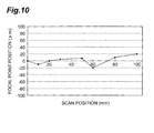
- Fig. 10 shows, as a comparative example, a graph, in which focal point positions of an imaging unit with respect to localized regions aligned along a single column on a horizontal sample setting surface are joined along the scan direction shown in Fig. 8.
- the focal point positions of the respective imaging units along the scan direction in an arbitrary column increase and decrease in sawtooth-like manner from plus 20 ⁇ m to minus 20 ⁇ m.
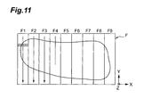
- the imaging object area F is partitioned into a plurality of strip-like imaging units F1 to F9.
- An imageable area of a one-dimensional CCD camera is a region, indicated by slanted lines in the imaging unit F 1 in Fig. 11 and having the X-axis direction as a longitudinal direction.
Landscapes
- Physics & Mathematics (AREA)
- Chemical & Material Sciences (AREA)
- Analytical Chemistry (AREA)
- General Physics & Mathematics (AREA)
- Optics & Photonics (AREA)
- Engineering & Computer Science (AREA)
- Multimedia (AREA)
- Computer Vision & Pattern Recognition (AREA)
- Microscoopes, Condenser (AREA)
- Lens Barrels (AREA)
- Automatic Focus Adjustment (AREA)
- Image Input (AREA)
Abstract
Description
- The present invention relates to a microscopic image capturing apparatus that, while scanning a surface of a sample, set on a sample setting stage, in a predetermined direction, successively captures localized microscopic images of the sample surface.
- A microscopic image capturing apparatus, having a sample setting stage that is movable along a plane (scan plane) orthogonal to an optical axis of an objective lens, has been known from before. Such a microscopic image capturing apparatus successively captures localized microscopic images of a sample surface while moving the sample setting stage, on which the sample is set, along the scan plane. In this process, a focal point of an imaging unit is finely adjusted to be successively set on desired imaging positions on the sample surface in accordance with the movement of the sample setting stage.
- As an example of a focusing apparatus applicable to the microscopic image capturing apparatus with the above-described structure, there is known a focusing apparatus described in
Patent Document 1. The focusing apparatus described inPatent Document 1 determines numerical formula information of a virtual plane, corresponding to a sample surface, in advance from coordinate information on three arbitrary points X, Y, and Z on the sample surface, determines Z-coordinate information of an observation point, with which an inclination component of the sample surface is corrected, based on the numerical formula information, and drives an objective lens in a Z-axis direction to set a focal point on the observation point, based on the Z-coordinate information.
Patent Document 1:Japanese Patent Application Laid-Open No. H9-304703 - The inventors have studied the conventional microscopic image capturing apparatus in detail, and as a result, have found problems as follows. Namely, when, for example, in the conventional microscopic image capturing apparatus, such as described in
Patent Document 1, a stepping motor, an so on, is employed as a focusing apparatus that drives an objective lens in Z-axis directions (directions along an optical axis of the objective lens), the following issue arises. - In other words, in an objective lens drive system arranged from a stepping motor, lost motion occurs due to errors in forward and reverse rotation of the motor, gear backlash, torsional rigidity of a ball screw mechanism, and so on. Thus, when the objective lens is driven in one direction (toward a positive side) along the Z-axis and then driven in an opposite direction (toward a negative side) immediately thereafter or is driven toward the negative side and then driven toward the positive side immediately thereafter, the objective lens becomes unable to be kept track of in real time and a focal point of a CCD camera or other imaging unit cannot be set reliably at each imaging position set inside an imaging object area.
- The present invention is made to solve the aforementioned problem, and it is an object to provide a microscopic image capturing apparatus having a structure that, in scanning an imageable area of an imaging unit in a predetermined direction within an imaging object area in which a sample is present, can reliably set a focal point of the imaging unit on each imaging position set inside the imaging object area regardless of the type of focusing actuator.
- A microscopic image capturing apparatus according to the present invention is a microscopic image capturing apparatus that successively captures localized microscopic images of a sample surface while scanning an imageable area of an imaging unit in a predetermined direction, and comprises a sample setting stage, an imaging unit of a CCD camera, and so on, an objective lens, a first driving mechanism, a second driving mechanism, and a control unit. The sample setting stage has a sample setting surface on which a microscopic observation sample can be set. The imaging unit is arranged so as to oppose the sample setting surface and successively captures a portion of the sample that is present inside an imageable area (a region that can be captured at once by the imaging unit) within an imaging object area on the sample setting surface. The objective lens is arranged between the imaging unit and the sample setting surface and forms, on the imaging unit, an image of the imageable area (a localized microscopic image of the sample that is the object of imaging by the imaging unit) within the imaging object area. The first driving mechanism moves at least one of either the sample setting stage or the objective lens along a scan plane that is orthogonal to an optical axis of the objective lens. The first driving mechanism thereby adjusts the relative positions of the sample setting stage and the objective lens. The second driving mechanism moves at least one of the sample setting stage and the objective lens along an optical axis direction of the objective lens. The second driving mechanism thereby adjusts the relative positions of the sample setting stage and the objective lens. The control unit, by controlling the first and second driving mechanisms, moves the imageable area of the imaging unit in a relative manner along a predetermined scan direction while adjusting the focal point position of the imaging unit in the imaging object area.
- Particularly, in the microscopic image capturing apparatus according to the present invention, the sample setting surface of the sample setting stage is inclined with respect to the scan plane. More specifically, the sample setting surface of the sample setting stage is inclined to a degree such that a straight line on the sample setting surface that intersects the optical axis of the objective lens intersects the scan plane at a predetermined angle.
- As described above, the microscopic image capturing apparatus according to the present invention is constituted so that as the sample setting stage and the objective lens move in a relative manner in the predetermined scan direction, the imageable area of the imaging unit moves in the predetermined scan direction with respect to the imaging object area. In this process, the control unit controls the first driving mechanism so that, while the imageable area of the imaging unit moves relatively in the predetermined scan direction within the imaging object area, the focal point position of the imaging unit is monotonously adjusted in only one direction along the optical axis of the objective lens. This "monotonous adjustment of the focal point position" includes a state in which the focal point position is kept fixed. The direction of fine adjustment of the objective lens onto the focal point position of the imaging unit is thus either a negative direction, with which the focal point position is made shallower with respect to the sample surface, or a positive direction, with which the focal point position is made deeper with respect to the sample surface.
- Also, preferably in the microscopic image capturing apparatus according to the present invention, the sample setting surface of the sample setting stage has an inclination such that when a slide glass on which a sample, such as a piece of tissue, is positioned is set on the sample setting surface, a surface of the slide glass that opposes the imaging unit across the objective lens is inclined with respect to the scan plane. The sample that is set on the sample setting surface is not fixed in volume or shape, and the inclination of the surface of the cover glass that covers the tissue piece may not depend on the inclination of the sample setting surface. In this case, the direction in which the focal point position of the imaging unit is finely adjusted may not stabilize in just one direction. Thus, as the inclination angle θ of the sample setting surface with respect to the scan plane, at least an angle by which the surface of the sample on the sample setting surface matches the direction of inclination of the sample setting surface is necessary (the inclination angles do not have to be matched necessarily).
- The present invention will be more fully understood from the detailed description given hereinbelow and the accompanying drawings, which are given by way of illustration only and are not to be considered as limiting the present invention.
- Further scope of applicability of the present invention will become apparent from the detailed description given hereinafter. However, it should be understood that the detailed description and specific examples, while indicating preferred embodiments of the invention, are given by way of illustration only, since various changes and modifications within the spirit and scope of the invention will be apparent to those skilled in the art from this detailed description.
- In accordance with the microscopic image capturing apparatus according to the present invention, the focal length of the imaging unit varies monotonously according to the inclination of the sample setting surface (this monotonous variation also includes the state where the focal length of the imaging unit is maintained) while the imageable area of the imaging unit moves in the predetermined scan direction within the imaging object area. As a result, the direction of fine adjustment of the position of the objective lens along the optical axis of the objective lens is restricted to just a fixed direction.
- In the microscopic image capturing apparatus according to the present invention, due to having the above arrangement, even when a stepping motor is applied as an actuator for focusing, the occurrence of lost motion in a driving system based on the stepping motor is suppressed effectively, and the focal point of the imaging unit can be set accurately at each imaging position set inside the imaging object area (clear localized microscopic images of specific portions of a sample surface can be obtained).
- Also, in accordance with the microscopic image capturing apparatus according to the present invention, the inclination of the sample setting surface of the sample setting stage is such that, when a sample is set on the sample setting surface, the surface of the sample that opposes the imaging unit across the objective lens is inclined with respect to the scan plane. In this case, the direction in which the objective lens is finely adjusted along the optical axis of the objective lens can be restricted to just a fixed direction regardless of the volume or shape of the sample.
- In the microscopic image capturing apparatus according to the present invention, due to having the above arrangement, even when a stepping motor is applied as an actuator for focusing, the occurrence of lost motion in a driving system based on the stepping motor is prevented reliably, and the focal point of the imaging unit can be set accurately at each imaging position set inside the imaging object area (clear localized microscopic images of specific portions of a sample surface can be obtained).
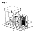
- Fig. 1 is a perspective view of a general arrangement of an embodiment of a microscopic image capturing apparatus according to the present invention;
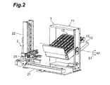
- Fig. 2 is a perspective view of an arrangement of a slide glass housing unit (including a cassette holder) shown in Fig. 1, and shows a state in which a holder portion of the cassette holder is inclined;
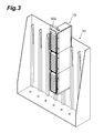
- Fig. 3 is a perspective view for describing a process of installing a slide glass cassette in a cassette portion shown in Fig. 2;
- Fig. 4 is a partial perspective view of an arrangement of an X-axis stage of a slide glass conveying unit shown in Fig. 2;
- Fig. 5 is a plan view of a slide glass setting unit, shown in Fig. 1, at a macro observation position;
- Fig. 6 is a plan view of the slide glass setting unit, shown in Fig. 1, at a scan position;
- Fig. 7 is a schematic view of an arrangement of a slide glass imaging unit shown in Fig. 1;
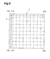
- Fig. 8 is a schematic view of a first example of partitioning of an imaging object area of a sample inside a slide glass, shown in Fig. 7, into a plurality of imaging units, each of a size substantially equal to an imageable area of the imaging unit;
- Fig. 9 is a graph that shows, along a scan direction shown in Fig. 8, positions of a focal point of the imaging unit with respect to imaging units aligned along a single column on a sample setting surface that is inclined as shown in Fig. 7;
- Fig 10 is a graph that shows, along the scan direction shown in Fig. 8, positions of the focal point of the imaging unit with respect to imaging units aligned along a single column on a horizontal sample setting surface as a comparative example;
- Fig. 11 is a schematic view of a second example of partitioning of the imaging object area of the sample inside the slide glass, shown in Fig. 7, into a plurality of imaging units, each of a size larger than the imageable area of the imaging unit; and
- Fig. 12 is a diagram for describing another method for determining the focal point position in the imaging object area.
- 1...slide glass housing unit (cassette holder); 2... slide glass conveying unit; 3 ... slide glass setting unit; 31... base stage; 32... stepping stage; 33... scanning stage; 33A...sample setting surface; 38...stage XY-axis driving mechanism (first driving mechanism); 4... slide glass imaging unit; 41...scan light source; 42 ... optical system; 43...CCD camera (imaging unit); 44... focusing Z-axis driving mechanism (second driving mechanism); 45...control apparatus; and SG... slide glass.
- In the following, embodiments of a microscopic image capturing apparatus according to the present invention will be explained in detail with reference to Figs. 1 to 12. In the explanation of the drawings, constituents identical to each other will be referred to with numerals identical to each other without repeating their overlapping descriptions. Also, in the following description, it shall be deemed that an upper portion and a lower portion of each drawing respectively correspond to an upper portion and a lower portion of the apparatus.
- Fig. 1 is a perspective view of a general arrangement of an embodiment of a microscopic image capturing apparatus according to the present invention.
- The microscopic image capturing apparatus shown in Fig. 1 captures a microscopic image of a slide glass (prepared slide) in which a sample, such as a tissue piece of a pathological tissue sample, is sealed. This microscopic image capturing apparatus has at least a slide
glass housing unit 1, which houses a plurality of slide glasses, each having a sample sealed therein, a slideglass conveying unit 2, which takes out and successively conveys slide glasses one at a time from the slideglass housing unit 1, a slideglass setting unit 3, on which the slide glass conveyed by the slideglass conveying unit 2 is set and which moves the slide glass in a predetermined direction, and a slideglass imaging unit 4, which captures microscopic images of the sample on the slideglass setting unit 3. - The slide
glass housing unit 1, as shown in Fig. 2, has a supportingframe 11, aholder portion 12, andslide glass cassettes 13. A cassette holder is arranged from at least the supportingframe 11 and theholder portion 12. Theholder portion 12 is held by the supportingframe 11 in a manner enabling rotation in directions indicated by thearrows S 1 about a horizontal axis AX, and the supportingframe 11 holds theholder portion 12 at an orientation (first orientation), in which theslide glass cassettes 13 are inclined so that takeout exits for the slide glasses face upward as shown in Fig. 2, and an orientation (second orientation), in which theslide glass cassettes 13 are set upright so that the takeout exits for the slide glasses are positioned vertically. Between the first and second orientations, theholder portion 12 rotates at a fixed rotation speed about the horizontal axis AX. In eachslide glass cassette 13 having a vertically long, box-like shape, as shown in Fig. 3, a plurality of slide glasses SG are layered in a state enabling takeout from an opening at the front side. - As shown in Fig. 2, the slide
glass conveying unit 2 is disposed in front of the slideglass housing unit 1, and has a Y-axis stage 21, which extends in left and right Y-axis directions, a Z-axis stage 22, which is position controlled in the left and right Y-axis directions by the Y-axis stage 21, and an X-axis stage, which is position controlled in upper and lower Z-axis directions by the Z-axis stage 22. TheX-axis stage 23, as shown in Fig. 4, is provided with a draw-outhandle 23A that is driven to proceed and retract in front and rear X-axis directions to draw out the slide glasses SG, housed in the respectiveslide glass cassettes 13 of the slideglass housing unit 1, one at a time. - Here, as shown in Figs. 5 and 6, the slide
glass setting unit 3 has a steppingstage 32 and ascanning stage 33. The steppingstage 32 is position controlled in the X-axis directions via a ball screw mechanism by a steppingmotor 31 A installed on abase stage 31. Thescanning stage 33 is position controlled in the Y-axis directions via a ball screw mechanism by a steppingmotor 32A installed on the steppingstage 32. Thescanning stage 33 functions as a sample setting stage. - In the
scanning stage 33 that functions as the sample setting stage is formed a notch that enables passage of the draw-outhandle 23A (see Fig. 4) of the slideglass conveying unit 2 with a slide glass SG set thereon. A sample setting surface, on which the slide glass SG is set, is arranged by respective sides of the notch supporting left and right edges of the slide glass SG, which is wider than the draw-outhandle 23A. - The
scanning stage 33 is fixed with apositioning block 34 that receives, for example, a left edge of the slide glass SG that has been set on the sample setting surface by the draw-outhandle 23A. Also, on thescanning stage 33, a slideglass presser arm 35, which presses, for example, a right edge of the slide glass SG toward thepositioning block 34 and thereby holds the slide glass SG at a predetermined position, is supported in a rotatable manner via apin 36. - The slide
glass presser arm 35 is constituted by apassive portion 35A, extending toward the left side of the slide glass SG, and apressing portion 35B, extending toward the right side of the slide glass SG, and has a U-like planar shape. The slideglass presser arm 35 is also urged by a spring so as to rotate in a counterclockwise direction about thepin 36. - In the slide
glass presser arm 35, when thescanning stage 33 moves to a macro observation position at a left end as shown in Fig. 5, thepassive portion 35A contacts a contactingplate 37, which is an immobile member at thebase stage 31 side, and thus rotates in a clockwise direction about a pin 33C. In this process, thepressing portion 35B separates from the right edge of the slide glass SG. - Furthermore, in the slide
glass presser arm 35, when thescanning stage 33 moves to a scan position at a right end as shown in Fig. 6, thepassive portion 35A separates from the contactingplate 37 and thus rotates in a counterclockwise direction about the pin 33C. In this process, thepressing portion 35B presses the right edge of the slide glass SG against thepositioning block 34 and functions to hold the slide glass SG at a predetermined position. - The slide
glass imaging unit 4 shown in Fig. 1, as schematically shown in Fig. 7, has ascan light source 41, anoptical system 42, aCCD camera 43, which is an imaging unit, a stage XY-axis driving mechanism 38 (first driving mechanism), a focusing Z-axis driving mechanism (second driving mechanism), and a control apparatus 5 (control unit). Thescan light source 41 illuminates imaging light from below onto the slide glass SG, set on thesample setting surface 33A of the scanning stage 33 (see Fig. 6). Theoptical system 42 includes anobjective lens 42A onto which imaging light that has been transmitted through the slide glass SG is made incident. TheCCD camera 43 receives the imaging light via theoptical system 42. The stage XY-axis driving mechanism 38 moves thescanning stage 33 along a scan plane orthogonal to an optical axis of theobjective lens 42A. The focusing Z-axis driving mechanism 44 performs position control of theCCD camera 43 and theobjective lens 42A of theoptical system 42 in an optical axis direction along the Z-axis and thereby adjusts a focal point position of theCCD camera 43 with respect to the slide glass SG. - The
CCD camera 43 is enabled to perform an operation of taking in a two-dimensional image. The focusing Z-axis driving mechanism 44 has a highly versatile arrangement that combines a stepping motor with a ball screw mechanism. Thecontrol apparatus 5 controls theCCD camera 43 and the focusing Z-axis driving mechanism 44 along with the stage XY-axis driving mechanism 38, which includes steppingmotors - The
control apparatus 5 is constituted by using, for example, personal computer hardware and software and includes an input/output interface, an A/D converter, a ROM (read-only memory), storing programs and data, a RAM (random access memory), temporarily storing input data, and so on, a CPU (central processing unit), executing programs, and so on, as the hardware. - The
control apparatus 5 controls the stage XY-axis driving mechanism 38 to move thescanning stage 33, on which the slide glass SG has been set, in a scan direction along the Y-axis and a stepping direction along the X-axis. In this process, thecontrol apparatus 5 performs position control of theobjective lens 42A in the optical axis direction along the Z-axis so that the focal point of theCCD camera 43 is successively set on respective imaging positions set inside an imaging object area that includes the sample sealed in the slide glass SG (fine adjustment of the focal point position of the CCD camera 43). Thecontrol apparatus 5 then controls theCCD camera 43 to successively take in localized microscopic images of the sample surface via theobjective lens 42A. - Here, because the focusing Z-
axis driving mechanism 44 has the structure that combines the stepping motor with the ball screw mechanism, when the drive direction is inverted, lost motion occurs due to errors in forward and reverse rotation of the motor, gear backlash, torsional rigidity of the ball screw mechanism, and so on. As a result, it is predicted that theobjective lens 42A cannot be kept track of in real time in optical axis directions along the Z-axis, making it difficult to set the focal point of theCCD camera 43 successively on respective portions (portions at which an imageable area of theCCD camera 43 is positioned) of the sample sealed in the slide glass SG. - Such circumstances must thus be avoided to enable the focal point of the
objective lens 42A to be set successively on respective portions (imaging positions in the imaging object area) of the sample. Thus, in the present embodiment, thesample setting surface 33A of thescanning stage 33 is inclined by just a predetermined inclination angle θ with respect to the scan plane orthogonal to the optical axis of theobjective lens 42A. The inclination of thesample setting surface 33A is set so as to be greater than the inclination of the surface of the slide glass SG in which the sample is sealed. - Fig. 8 shows a first example, in which an imaging object area F that includes the sample is defined as a square with each side being 25mm and the imaging object area F is partitioned vertically and laterally into 10 x 10 lattice cells so that the imaging object area F is constituted of square imaging units F00 to F99, each having sides of 2.5mm. In the figure, the vertical direction of the solid line arrow directed from the imaging unit F00 to the imaging unit F09 is the scan direction, and the lateral direction of the solid line arrow directed from the imaging unit F00 to the imaging unit F90 is the stepping direction. Also, in the example of Fig. 8, the size of the imageable area of the
CCD camera 43 is substantially the same as each imaging unit, and thus the position of a central point P of each imaging unit is the focal point position of theCCD camera 43 with respect to the imaging unit. Also, in the present Description, because the image of the imageable area that is formed via theoptical system 42 on theCCD camera 4 is defined as the localized microscopic image, each localized microscopic image that is obtained is a single imaging unit in the first example of Fig. 8. - Here, in a case where the sample is a pathological tissue sample, a maximum inclination, which joins a high point and a low point of the imaging object area F within a length of 25mm in the scan direction along a single column from the imaging unit F00 to the imaging unit F09, is normally approximately 10 to 20µm/25mm. Thus, in the present embodiment, the magnitude of the inclination of the
sample setting surface 33A is set, for example, to 50µm/25mm (200µm/100mm), which is within the range of 25 to 50µm/25mm (=1 to 2µm/mm). The inclination of thesample setting surface 33A is set so that the surface is inclined along the scan direction, that is for example, so that a scan starting position is high and an ending position is low. - An operation of the microscopic image capturing apparatus arranged as described above shall now be described. For the slide glass SG that is set on the inclined
sample setting surface 33A of thescanning stage 33 shown in Fig. 7, the microscopic image capturing apparatus successively captures localized microscopic images of the respective imaging units F00 to F99 in the imaging object area F (see Fig. 8) that includes the sample sealed in the slide glass SG. - First, the
control apparatus 5 acquires focal point position data of the respective central points P of the imaging units F00 to F99 shown in Fig. 8 and stores these in the form of a focus map. - In preparing the focus map, the
control apparatus 5 outputs a control signal to the stage XY-axis driving mechanism 38 to make thescanning stage 33 move successively in the scan direction and the stepping direction so that the imaging position of theCCD camera 43 successively matches the respective imaging units F00 to F99 shown in Fig. 8. That is, thescanning stage 33 moves so that each of the imaging units F00 to F99 becomes positioned immediately below theobjective lens 42A in order. - In the meantime, the
control apparatus 5 acquires focal point data of theCCD camera 43 at each central point P of each of the imaging units F00 to F99 that becomes positioned immediately below theobjective lens 42A. That is, thecontrol apparatus 5 outputs a control signal to the focusing Z-axis driving mechanism 44 to make theobjective lens 42A move continuously along the Z-axis (optical axis direction of theobjective lens 42A) above and below the focal point position of theCCD camera 43. At the same time, thecontrol apparatus 5 outputs a control signal to theCCD camera 43 to make theCCD camera 43 capture a plurality of microscopic images that differ in focal point position. - The
control apparatus 5 then comparatively evaluates the contrast, brightness, and other image characteristics of the plurality of microscopic images that differ in focal point position, acquires the focal point positions at which clear images are obtained as focal point data of theCCD camera 43 at the respective central points P of the imaging units F00 to F99, and thereby prepares the focus map of the imaging units F00 to F99. - After preparing the focus map of the imaging units F00 to F99, the
control apparatus 5 outputs a control signal to the stage XY-axis driving mechanism 38 to make thescanning stage 33 move as shown in Fig. 8 so that the respective imaging units F00 to F99 successively coincide with the imageable area of the CCD camera 43 (makes thescanning stage 33 move in the scan direction and the stepping direction shown in Fig. 8 so that theobjective lens 42A becomes positioned immediately above each of the imaging units F00 to F99). In the meantime, thecontrol apparatus 5 outputs a control signal to the focusing Z-axis driving mechanism 44 to make theobjective lens 42A move in the Z-axis direction and be set at each focal point position of theCCD camera 43 stored in the focus map. Thecontrol apparatus 5 then outputs a control signal to theCCD camera 43 at each predetermined focal position and makes theCCD camera 43 capture a localized microscopic image of each of the imaging units F00 to F99. - Here, Fig. 9 is a graph, in which focal point positions, stored as data in the focus map, are joined along the scan direction in an arbitrary column of the imaging object area F. In the figure, the inclined line indicated by the alternate long and two short dashes line indicates the
sample setting surface 33A (reference surface) with an inclination, for example, of 50µm/25mm (200µm/100mm) as described above. - As shown in Fig. 9, the focal point positions of the
CCD camera 43 along the scan direction in the arbitrary column decrease successively in a step-like manner from plus 100µm to minus 100µm. This indicates that the direction in which the focusing Z-axis driving mechanism 44 finely adjusts theobjective lens 42A along the optical axis, that is, the Z-axis to set the focal point of theCCD camera 43 on the center P of each imaging unit is restricted to just the negative direction. - Thus, in accordance with the microscopic image capturing apparatus according to the present embodiment, despite having the focusing Z-
axis driving mechanism 44 with the structure combining the stepping motor with the ball screw mechanism, lost motion does not occur in the focusing Z-axis driving mechanism 44. As a result, the focal point of theCCD camera 43 can be set accurately on the portion of the sample that is matched with the imageable area via theobjective lens 42A. - On the other hand, Fig. 10 shows, as a comparative example, a graph, in which focal point positions of an imaging unit with respect to localized regions aligned along a single column on a horizontal sample setting surface are joined along the scan direction shown in Fig. 8. In the graph shown in Fig. 10, the focal point positions of the respective imaging units along the scan direction in an arbitrary column increase and decrease in sawtooth-like manner from plus 20µm to minus 20µm. This indicates that the direction in which the focusing Z-
axis driving mechanism 44 finely adjusts theobjective lens 42A along the Z-axis (along the optical axis of theobjective lens 42A) to set the focal point of theCCD camera 43 on the center P of each imaging unit changes from the positive direction to the negative direction and from the negative direction to the positive direction. In this case, lost motion occurs in the focusing Z-axis driving mechanism 44, and as a result, the focal point of theCCD camera 43 cannot be set accurately on each portion of the sample captured by theobjective lens 42A or to be more specific, on the center P of each imaging unit. - The microscopic image capturing apparatus according to the present invention is not restricted to the above-described embodiment. For example, the focusing Z-
axis driving mechanism 44 shown in Fig. 7 may perform position control of thescanning stage 33 in a Z-axis direction that coincides with a direction of the optical axis of theobjective lens 42A. Also, in place of providing thescanning stage 33, theoptical system 42 and theCCD camera 43 may be provided with an XY-axis driving mechanism or an XYZ-axis driving system. - The
CCD camera 43 shown in Fig. 7 may be a one-dimensional CCD camera that performs an operation of taking in a one-dimensional image. For example, a general line sensor or a TDI sensor, and so on, may be applied. The microscopic image capturing operation by a one-dimensional CCD camera or other one-dimensional imaging unit is performed as follows. Fig. 11 is a schematic view of a second example, in which the imaging object area that includes the entire sample inside the slide glass, shown in Fig. 7, is partitioned into a plurality of imaging units, each of a size larger than the imageable area of the imaging unit. - As shown in Fig. 11, the imaging object area F is partitioned into a plurality of strip-like imaging units F1 to F9. An imageable area of a one-dimensional CCD camera is a region, indicated by slanted lines in the
imaging unit F 1 in Fig. 11 and having the X-axis direction as a longitudinal direction. By the imageable area being scanned in a scan direction (negative direction along the Y-axis) on thescanning stage 43, on which a sample is set, an image of the imaging unit F1 (an image with a strip-like shape), in which a plurality of localized microscopic images of the imageable area that are formed and acquired successively are aligned along the Y-axis direction, is obtained. The strip-like image of theimaging unit F 1 thus becomes a single imaging unit in the second example of Fig. 11. Furthermore, as shown in Fig. 11, by the scanning of the imageable area, performed in theimaging unit F 1, being repeated upon performing stepping in the longitudinal direction of the imaging object area F (the positive X-axis direction), strip-like images of the imaging units F1 to F9 are respectively obtained. By synthesizing the thus obtained strip-like images of the imaging units F1 to F9 in a state of being aligned in the X-axis direction, an overall image of the sample (a microscopic image of the entire imaging object area F) is formed. - In addition, although the embodiment described above is described as an example of the
scanning stage 33, having thesample setting surface 33A that is inclined with the scan plane orthogonal to the optical axis of theobjective lens 42A, the present invention is not restricted thereto and, for example, a commercially available scanning stage may be fixed so that the sample setting surface thereof is inclined with respect to the scan plane. Or, an inclining stage or a tilt stage, with which the inclination angle can be varied, may be applied. In a case where a stage with which the inclination angle can be varied is applied, the inclination angle of the sample setting surface with respect to the scan plane is preferably set based on a focus map prepared for a sample set in a state in which the sample setting surface is not inclined. - Furthermore, in regard to the preparation of the focus map, although the focal point position data at the respective central points P of the imaging units F00 to F99 are acquired in Fig. 8, the present invention is not restricted thereto. Fig. 12 is a diagram for describing another method for acquiring focal point information for the entire imaging object area F of a sample. In the focal point information acquisition method shown in Fig. 12, three focal point measuring positions PF are set for the imaging object area F. By focal point measurement being performed by the above-described method for each of the three focal point measuring positions PF, in-focus point positions are determined. From the in-focus point positions determined based on the three focal point measuring positions PF, an in-focus point position of an arbitrary position inside the imaging object area F is determined by linear interpolation. The in-focus point positions and other focal point information of respective portions of the imaging object area F can be acquired efficiently by such a method. Also, by setting four or more focal point measuring positions PF in the imaging object area F and determining the in-focus point position of an arbitrary position inside the imaging object area F by a least squares method, a more precise focal point position control is enabled.
- From the invention thus described, it will be obvious that the embodiments of the invention may be varied in many ways. Such variations are not to be regarded as a departure from the spirit and scope of the invention, and all such modifications as would be obvious to one skilled in the art are intended for inclusion within the scope of the following claims.
- The microscopic image capturing apparatus according to the present invention can be applied to an inspection apparatus for cell analysis, and so on.
Claims (5)
- A microscopic image capturing apparatus, comprising:a sample setting stage having a sample setting surface on which a sample can be set;an imaging unit, arranged so as to oppose the sample setting surface, successively imaging respective portions in an imaging object area on said sample setting surface;an objective lens, arranged between said imaging unit and said sample setting surface, forming, on said imaging unit, a localized microscopic image of an area, within the imaging object area, that is imageable by said imaging unit;a first driving mechanism adjusting relative positions of said sample setting stage and said objective lens, by relatively moving at least one of said sample setting stage and said objective lens along a scan plane orthogonal to an optical axis of said objective lens;a second driving mechanism adjusting relative positions of said sample setting stage and said objective lens, by relatively moving at least one of said sample setting stage and said objective lens along an optical axis direction of said objective lens; anda control unit, by controlling said first and second driving mechanisms, relatively moving the imageable area of said imaging unit along a predetermined scan direction while adjusting the focal point position of said imaging unit in the imaging object area,wherein said sample setting surface of said sample setting stage is inclined with respect to the scan plane.
- A microscopic image capturing apparatus according to claim 1, wherein said control unit controls said first driving mechanism such that the focal point position of said imaging unit is monotonously adjusted in only one direction along the optical axis of said objective lens while the imageable area of said imaging unit is being relatively moved in the predetermined scan direction within the imaging object area.
- A microscopic image capturing apparatus according to claim 1, wherein said sample setting surface of said sample setting stage has an inclination such that a straight line on said sample setting surface that intersects the optical axis of said objective lens intersects the scan plane at a predetermined angle.
- A microscopic image capturing apparatus according to claim 1, wherein said sample setting surface of said sample setting stage has an inclination of 1 to 2µm/mm along the predetermined scan direction.
- A microscopic image capturing apparatus according to claim 1, wherein said sample setting surface of said sample setting stage has an inclination such that, when a sample is set on said sample setting surface, a surface of the sample that opposes said imaging unit across said objective lens is inclined with respect to the scan plane.
Applications Claiming Priority (2)
| Application Number | Priority Date | Filing Date | Title |
|---|---|---|---|
| JP2005077990 | 2005-03-17 | ||
| PCT/JP2006/305434 WO2006098443A1 (en) | 2005-03-17 | 2006-03-17 | Microscopic image capturing device |
Publications (3)
| Publication Number | Publication Date |
|---|---|
| EP1865354A1 true EP1865354A1 (en) | 2007-12-12 |
| EP1865354A4 EP1865354A4 (en) | 2011-01-26 |
| EP1865354B1 EP1865354B1 (en) | 2016-03-16 |
Family
ID=36991787
Family Applications (1)
| Application Number | Title | Priority Date | Filing Date |
|---|---|---|---|
| EP06729423.1A Expired - Lifetime EP1865354B1 (en) | 2005-03-17 | 2006-03-17 | Microscopic image capturing device |
Country Status (4)
| Country | Link |
|---|---|
| US (2) | US8422127B2 (en) |
| EP (1) | EP1865354B1 (en) |
| JP (2) | JP4871264B2 (en) |
| WO (1) | WO2006098443A1 (en) |
Cited By (9)
| Publication number | Priority date | Publication date | Assignee | Title |
|---|---|---|---|---|
| CN103033921A (en) * | 2011-10-05 | 2013-04-10 | 索尼公司 | Image acquisition apparatus, image acquisition method, and computer program |
| CN104871064A (en) * | 2012-12-20 | 2015-08-26 | 浜松光子学株式会社 | Optical observation device |
| CN105143953A (en) * | 2013-04-26 | 2015-12-09 | 浜松光子学株式会社 | Image acquisition device and method and system for creating focus map for specimen |
| US9661212B2 (en) | 2013-04-26 | 2017-05-23 | Hamamatsu Photonics K.K. | Image acquisition device and focusing method for image acquisition device |
| EP2983029A4 (en) * | 2013-04-05 | 2017-07-19 | Riken | Microscope, focusing unit, fluid holding unit, and optical unit |
| WO2017037486A3 (en) * | 2015-08-31 | 2017-09-14 | 3Dhistech Kft. | Confocal slide-digitizing apparatus |
| EP3239691A4 (en) * | 2014-12-26 | 2018-08-22 | Sysmex Corporation | Cell imaging device, cell imaging method, and sample cell |
| US10330910B2 (en) | 2013-04-26 | 2019-06-25 | Hamamatsu Photonics K.K. | Image acquisition device and method and system for acquiring focusing information for specimen |
| EP3829158A4 (en) * | 2018-07-23 | 2021-09-01 | GeneMind Biosciences Company Limited | IMAGING PROCESS, DEVICE, AND SYSTEM |
Families Citing this family (26)
| Publication number | Priority date | Publication date | Assignee | Title |
|---|---|---|---|---|
| US7825488B2 (en) * | 2006-05-31 | 2010-11-02 | Advanced Analogic Technologies, Inc. | Isolation structures for integrated circuits and modular methods of forming the same |
| CN101194263B (en) * | 2005-06-13 | 2012-02-22 | 三路影像公司 | System and method for re-locating an object in a sample on a slide with a microscope imaging device |
| US8530243B2 (en) * | 2009-04-20 | 2013-09-10 | Bio-Rad Laboratories Inc. | Non-scanning SPR system |
| JP5443096B2 (en) * | 2009-08-12 | 2014-03-19 | 株式会社ニューフレアテクノロジー | Semiconductor manufacturing apparatus and semiconductor manufacturing method |
| JP5732284B2 (en) * | 2010-08-27 | 2015-06-10 | 株式会社ニューフレアテクノロジー | Film forming apparatus and film forming method |
| GB2494734B (en) * | 2011-09-14 | 2016-04-06 | Malvern Instr Ltd | Apparatus and method for measuring particle size distribution by light scattering |
| JP5981241B2 (en) * | 2012-06-25 | 2016-08-31 | 浜松ホトニクス株式会社 | Microscope imaging apparatus and microscope imaging method |
| JP6027875B2 (en) * | 2012-12-07 | 2016-11-16 | オリンパス株式会社 | Imaging apparatus and microscope system |
| JP6147006B2 (en) * | 2013-01-09 | 2017-06-14 | オリンパス株式会社 | Imaging apparatus, microscope system, and imaging method |
| JP6134249B2 (en) | 2013-11-01 | 2017-05-24 | 浜松ホトニクス株式会社 | Image acquisition device and image acquisition method of image acquisition device |
| WO2015077819A1 (en) | 2013-11-26 | 2015-06-04 | Ansell Limited | Effervescent texturing |
| JP6559706B2 (en) | 2014-01-27 | 2019-08-14 | ビーコ インストルメンツ インコーポレイテッド | Wafer carrier with holding pockets with compound radius for chemical vapor deposition systems |
| CN106133873B (en) | 2014-03-12 | 2019-07-05 | 应用材料公司 | Wafer rotation in semiconductor chamber |
| EP3428573B1 (en) * | 2016-03-09 | 2021-11-03 | Hamamatsu Photonics K.K. | Measuring device, observing device and measuring method |
| DE102016107336B4 (en) * | 2016-04-20 | 2017-11-02 | Carl Zeiss Industrielle Messtechnik Gmbh | Coordinate measuring machine, method for producing a coordinate measuring machine and method for measuring an optical filter |
| CN106094194B (en) * | 2016-08-17 | 2019-06-14 | 江浩 | The acquisition methods, imaging device of samples pictures and its method for obtaining samples pictures under microscope |
| US10636628B2 (en) | 2017-09-11 | 2020-04-28 | Applied Materials, Inc. | Method for cleaning a process chamber |
| WO2020046567A1 (en) * | 2018-08-29 | 2020-03-05 | Applied Materials, Inc. | Chamber injector |
| JP7312020B2 (en) * | 2019-05-30 | 2023-07-20 | 株式会社Screenホールディングス | Heat treatment method and heat treatment apparatus |
| US11523046B2 (en) * | 2019-06-03 | 2022-12-06 | Molecular Devices, Llc | System and method to correct for variation of in-focus plane across a field of view of a microscope objective |
| US11499817B2 (en) * | 2020-05-29 | 2022-11-15 | Mitutoyo Corporation | Coordinate measuring machine with vision probe for performing points-from-focus type measurement operations |
| TW202212620A (en) * | 2020-06-02 | 2022-04-01 | 荷蘭商Asm Ip私人控股有限公司 | Apparatus for processing substrate, method of forming film, and method of controlling apparatus for processing substrate |
| US20240010448A1 (en) * | 2020-12-08 | 2024-01-11 | Sony Group Corporation | Glass slide conveyance device and glass slide image capturing system |
| CN113686857B (en) * | 2021-08-31 | 2024-07-19 | 杭州智微信息科技有限公司 | A slide box rotating lifting structure for bone marrow smear scanner |
| IL298509B2 (en) * | 2022-11-23 | 2024-04-01 | Applied Materials Israel Ltd | Optical systems and method of calibrating the same |
| JP2025185817A (en) * | 2024-06-11 | 2025-12-23 | 矢崎総業株式会社 | Image inspection device and image inspection method |
Family Cites Families (67)
| Publication number | Priority date | Publication date | Assignee | Title |
|---|---|---|---|---|
| US3826558A (en) * | 1972-07-21 | 1974-07-30 | Us Air Force | Mechanical rotary tilt stage |
| US4328553A (en) * | 1976-12-07 | 1982-05-04 | Computervision Corporation | Method and apparatus for targetless wafer alignment |
| JPS60134117U (en) * | 1984-02-16 | 1985-09-06 | アルプス電気株式会社 | optical rotary encoder |
| US4819167A (en) * | 1987-04-20 | 1989-04-04 | Applied Materials, Inc. | System and method for detecting the center of an integrated circuit wafer |
| US4833790A (en) * | 1987-05-11 | 1989-05-30 | Lam Research | Method and system for locating and positioning circular workpieces |
| JPH0658795B2 (en) | 1989-05-09 | 1994-08-03 | 日本電子株式会社 | Dynamic focus circuit |
| US5155336A (en) * | 1990-01-19 | 1992-10-13 | Applied Materials, Inc. | Rapid thermal heating apparatus and method |
| JPH04110960A (en) | 1990-08-31 | 1992-04-13 | Sharp Corp | Electrifying device of electrophotographic device |
| JP2572767Y2 (en) * | 1991-01-25 | 1998-05-25 | 日本分光株式会社 | Microscopic infrared spectrum measurement device |
| US5337178A (en) * | 1992-12-23 | 1994-08-09 | International Business Machines Corporation | Titlable optical microscope stage |
| JPH06309035A (en) * | 1993-04-21 | 1994-11-04 | Hitachi Ltd | Sample stage |
| JPH0756093A (en) * | 1993-08-19 | 1995-03-03 | Fujitsu Ltd | Microscope stage equipment |
| JPH07174980A (en) | 1993-12-17 | 1995-07-14 | Olympus Optical Co Ltd | Microscope stage |
| JPH0821961A (en) * | 1994-07-08 | 1996-01-23 | Matsushita Electric Ind Co Ltd | Microscope autofocus device |
| US5660472A (en) * | 1994-12-19 | 1997-08-26 | Applied Materials, Inc. | Method and apparatus for measuring substrate temperatures |
| US5755511A (en) * | 1994-12-19 | 1998-05-26 | Applied Materials, Inc. | Method and apparatus for measuring substrate temperatures |
| US5822213A (en) * | 1996-03-29 | 1998-10-13 | Lam Research Corporation | Method and apparatus for determining the center and orientation of a wafer-like object |
| JPH09304703A (en) | 1996-05-16 | 1997-11-28 | Olympus Optical Co Ltd | Focusing device |
| US5781693A (en) * | 1996-07-24 | 1998-07-14 | Applied Materials, Inc. | Gas introduction showerhead for an RTP chamber with upper and lower transparent plates and gas flow therebetween |
| US6395363B1 (en) * | 1996-11-05 | 2002-05-28 | Applied Materials, Inc. | Sloped substrate support |
| US6157106A (en) * | 1997-05-16 | 2000-12-05 | Applied Materials, Inc. | Magnetically-levitated rotor system for an RTP chamber |
| US6123766A (en) * | 1997-05-16 | 2000-09-26 | Applied Materials, Inc. | Method and apparatus for achieving temperature uniformity of a substrate |
| US6226453B1 (en) * | 1997-09-16 | 2001-05-01 | Applied Materials, Inc. | Temperature probe with fiber optic core |
| DE19748088A1 (en) * | 1997-10-30 | 1999-05-12 | Wacker Siltronic Halbleitermat | Method and device for detecting a misalignment of a semiconductor wafer |
| JP3863993B2 (en) * | 1998-03-18 | 2006-12-27 | オリンパス株式会社 | microscope |
| US6185030B1 (en) * | 1998-03-20 | 2001-02-06 | James W. Overbeck | Wide field of view and high speed scanning microscopy |
| US6164816A (en) * | 1998-08-14 | 2000-12-26 | Applied Materials, Inc. | Tuning a substrate temperature measurement system |
| JP2000241713A (en) | 1999-02-16 | 2000-09-08 | Leica Microsystems Wetzler Gmbh | Holder for sample carrier |
| US6654668B1 (en) * | 1999-02-16 | 2003-11-25 | Tokyo Electron Limited | Processing apparatus, processing system, distinguishing method, and detecting method |
| US6275742B1 (en) * | 1999-04-16 | 2001-08-14 | Berkeley Process Control, Inc. | Wafer aligner system |
| JP3437118B2 (en) * | 1999-04-23 | 2003-08-18 | 東芝機械株式会社 | Wafer heating apparatus and control method therefor |
| US6423949B1 (en) * | 1999-05-19 | 2002-07-23 | Applied Materials, Inc. | Multi-zone resistive heater |
| US6586343B1 (en) * | 1999-07-09 | 2003-07-01 | Applied Materials, Inc. | Method and apparatus for directing constituents through a processing chamber |
| US6500266B1 (en) * | 2000-01-18 | 2002-12-31 | Applied Materials, Inc. | Heater temperature uniformity qualification tool |
| US7518652B2 (en) * | 2000-05-03 | 2009-04-14 | Aperio Technologies, Inc. | Method and apparatus for pre-focus in a linear array based slide scanner |
| US6610968B1 (en) * | 2000-09-27 | 2003-08-26 | Axcelis Technologies | System and method for controlling movement of a workpiece in a thermal processing system |
| US6350964B1 (en) * | 2000-11-09 | 2002-02-26 | Applied Materials, Inc. | Power distribution printed circuit board for a semiconductor processing system |
| US20020131167A1 (en) * | 2000-11-09 | 2002-09-19 | Nguyen Francis T. | Sample holder for an imaging system |
| US6634882B2 (en) * | 2000-12-22 | 2003-10-21 | Asm America, Inc. | Susceptor pocket profile to improve process performance |
| JP4603177B2 (en) | 2001-02-02 | 2010-12-22 | オリンパス株式会社 | Scanning laser microscope |
| KR100416292B1 (en) * | 2001-02-24 | 2004-01-31 | (주)지우텍 | Device for detecting wafer positioning failure on semiconductor processing device and method thereof |
| JP4690584B2 (en) * | 2001-06-06 | 2011-06-01 | 有限会社ユナテック | Surface evaluation apparatus and surface evaluation method |
| JP4631218B2 (en) | 2001-06-21 | 2011-02-16 | 株式会社ニコン | Microscope equipment |
| US6924929B2 (en) * | 2002-03-29 | 2005-08-02 | National Institute Of Radiological Sciences | Microscope apparatus |
| US6900877B2 (en) * | 2002-06-12 | 2005-05-31 | Asm American, Inc. | Semiconductor wafer position shift measurement and correction |
| US7778533B2 (en) * | 2002-09-12 | 2010-08-17 | Applied Materials, Inc. | Semiconductor thermal process control |
| JP4110960B2 (en) | 2002-11-17 | 2008-07-02 | 株式会社セガ | Information terminal with touch panel |
| WO2004064134A1 (en) * | 2003-01-09 | 2004-07-29 | Dainippon Screen Mfg. Co., Ltd | Substrate treatment system, substrate treatment device, program, and recording medium |
| US6950774B2 (en) * | 2003-01-16 | 2005-09-27 | Asm America, Inc. | Out-of-pocket detection system using wafer rotation as an indicator |
| US7505832B2 (en) * | 2003-05-12 | 2009-03-17 | Applied Materials, Inc. | Method and apparatus for determining a substrate exchange position in a processing system |
| US6855916B1 (en) * | 2003-12-10 | 2005-02-15 | Axcelis Technologies, Inc. | Wafer temperature trajectory control method for high temperature ramp rate applications using dynamic predictive thermal modeling |
| US8500916B2 (en) * | 2004-11-05 | 2013-08-06 | HGST Netherlands B.V. | Method for aligning wafers within wafer processing equipment |
| US7364922B2 (en) * | 2005-01-24 | 2008-04-29 | Tokyo Electron Limited | Automated semiconductor wafer salvage during processing |
| US8021484B2 (en) * | 2006-03-30 | 2011-09-20 | Sumco Techxiv Corporation | Method of manufacturing epitaxial silicon wafer and apparatus therefor |
| US8104951B2 (en) * | 2006-07-31 | 2012-01-31 | Applied Materials, Inc. | Temperature uniformity measurements during rapid thermal processing |
| US8162584B2 (en) * | 2006-08-23 | 2012-04-24 | Cognex Corporation | Method and apparatus for semiconductor wafer alignment |
| JP4870604B2 (en) * | 2007-03-29 | 2012-02-08 | 株式会社ニューフレアテクノロジー | Vapor growth equipment |
| US8057602B2 (en) * | 2007-05-09 | 2011-11-15 | Applied Materials, Inc. | Apparatus and method for supporting, positioning and rotating a substrate in a processing chamber |
| US8057601B2 (en) * | 2007-05-09 | 2011-11-15 | Applied Materials, Inc. | Apparatus and method for supporting, positioning and rotating a substrate in a processing chamber |
| US8860955B2 (en) * | 2007-12-27 | 2014-10-14 | Lam Research Corporation | Arrangements and methods for determining positions and offsets |
| US8249436B2 (en) * | 2008-05-02 | 2012-08-21 | Applied Materials, Inc. | System for non radial temperature control for rotating substrates |
| KR101182502B1 (en) * | 2008-09-30 | 2012-09-12 | 도쿄엘렉트론가부시키가이샤 | Method for detecting abnormal placement state of substrate, substrate processing method, computer-readable storage medium and substrate processing apparatus |
| US8150242B2 (en) * | 2008-10-31 | 2012-04-03 | Applied Materials, Inc. | Use of infrared camera for real-time temperature monitoring and control |
| US8109669B2 (en) * | 2008-11-19 | 2012-02-07 | Applied Materials, Inc. | Temperature uniformity measurement during thermal processing |
| DE102009010555A1 (en) * | 2009-02-25 | 2010-09-02 | Siltronic Ag | Method for detecting a misalignment of a semiconductor wafer during a thermal treatment |
| JP5384220B2 (en) * | 2009-06-22 | 2014-01-08 | 東京応化工業株式会社 | Alignment apparatus and alignment method |
| JP5038381B2 (en) * | 2009-11-20 | 2012-10-03 | 株式会社東芝 | Susceptor and deposition system |
-
2006
- 2006-03-17 JP JP2007508232A patent/JP4871264B2/en not_active Expired - Fee Related
- 2006-03-17 US US11/886,255 patent/US8422127B2/en active Active
- 2006-03-17 WO PCT/JP2006/305434 patent/WO2006098443A1/en not_active Ceased
- 2006-03-17 EP EP06729423.1A patent/EP1865354B1/en not_active Expired - Lifetime
-
2011
- 2011-09-30 JP JP2011217896A patent/JP5209103B2/en not_active Expired - Lifetime
-
2012
- 2012-09-12 US US13/611,227 patent/US20130084390A1/en not_active Abandoned
Cited By (22)
| Publication number | Priority date | Publication date | Assignee | Title |
|---|---|---|---|---|
| CN103033921A (en) * | 2011-10-05 | 2013-04-10 | 索尼公司 | Image acquisition apparatus, image acquisition method, and computer program |
| CN104871064B (en) * | 2012-12-20 | 2017-10-17 | 浜松光子学株式会社 | Light observes device |
| CN104871064A (en) * | 2012-12-20 | 2015-08-26 | 浜松光子学株式会社 | Optical observation device |
| US9846267B2 (en) | 2012-12-20 | 2017-12-19 | Hamamatsu Photonics K.K. | Optical observation device |
| US10712547B2 (en) | 2013-04-05 | 2020-07-14 | Riken | Microscope, focusing unit, fluid holding unit, and optical unit |
| EP2983029A4 (en) * | 2013-04-05 | 2017-07-19 | Riken | Microscope, focusing unit, fluid holding unit, and optical unit |
| US9880378B2 (en) | 2013-04-05 | 2018-01-30 | Riken | Microscope, focusing unit, fluid holding unit, and optical unit |
| US10222601B2 (en) | 2013-04-05 | 2019-03-05 | Riken | Microscope, focusing unit, fluid holding unit, and optical unit |
| US10598916B2 (en) | 2013-04-26 | 2020-03-24 | Hamamatsu Photonics K.K. | Image acquisition device and method and system for acquiring focusing information for specimen |
| US9661212B2 (en) | 2013-04-26 | 2017-05-23 | Hamamatsu Photonics K.K. | Image acquisition device and focusing method for image acquisition device |
| CN105143953A (en) * | 2013-04-26 | 2015-12-09 | 浜松光子学株式会社 | Image acquisition device and method and system for creating focus map for specimen |
| US10330910B2 (en) | 2013-04-26 | 2019-06-25 | Hamamatsu Photonics K.K. | Image acquisition device and method and system for acquiring focusing information for specimen |
| US10348954B2 (en) | 2013-04-26 | 2019-07-09 | Hamamatsu Photonics K.K. | Image acquisition device and method and system for creating focus map for specimen |
| EP3239691A4 (en) * | 2014-12-26 | 2018-08-22 | Sysmex Corporation | Cell imaging device, cell imaging method, and sample cell |
| US10732168B2 (en) | 2014-12-26 | 2020-08-04 | Sysmex Corporation | Cell imaging device, cell imaging method, and sample cell |
| EP3968004A1 (en) * | 2014-12-26 | 2022-03-16 | Sysmex Corporation | Cell imaging device, cell imaging method, and sample cell |
| US10649195B2 (en) | 2015-08-31 | 2020-05-12 | 3Dhistech Kft. | Confocal slide-digitizing apparatus |
| WO2017037486A3 (en) * | 2015-08-31 | 2017-09-14 | 3Dhistech Kft. | Confocal slide-digitizing apparatus |
| EP3829158A4 (en) * | 2018-07-23 | 2021-09-01 | GeneMind Biosciences Company Limited | IMAGING PROCESS, DEVICE, AND SYSTEM |
| US11368614B2 (en) | 2018-07-23 | 2022-06-21 | Genemind Biosciences Company Limited | Imaging method, device and system |
| US11575823B2 (en) | 2018-07-23 | 2023-02-07 | Genemind Biosciences Company Limited | Imaging method, device and system |
| EP4679851A1 (en) * | 2018-07-23 | 2026-01-14 | GeneMind Biosciences Company Limited | Imaging method, device and system |
Also Published As
| Publication number | Publication date |
|---|---|
| US20090002811A1 (en) | 2009-01-01 |
| JP4871264B2 (en) | 2012-02-08 |
| JP2012042970A (en) | 2012-03-01 |
| JPWO2006098443A1 (en) | 2008-08-28 |
| EP1865354A4 (en) | 2011-01-26 |
| EP1865354B1 (en) | 2016-03-16 |
| US8422127B2 (en) | 2013-04-16 |
| JP5209103B2 (en) | 2013-06-12 |
| US20130084390A1 (en) | 2013-04-04 |
| WO2006098443A1 (en) | 2006-09-21 |
Similar Documents
| Publication | Publication Date | Title |
|---|---|---|
| EP1865354B1 (en) | Microscopic image capturing device | |
| CN114326140B (en) | System and method for aligning the optical axis of an optical component part to be perpendicular to a workpiece surface using multi-point autofocus | |
| US9575301B2 (en) | Device for a microscope stage | |
| KR101429866B1 (en) | Laser processing machine | |
| EP2916160B1 (en) | Image acquisition device and method for focusing image acquisition device | |
| RU2713074C1 (en) | Device for forming microscopic images using a mirror and a system and a method of calibrating the position of microneedles | |
| US10838187B2 (en) | Slide, set of slide and cover glass, and microscope system | |
| CN111183387A (en) | Opposed edge system for scanning and processing glass slides | |
| EP1775617A1 (en) | Autofocus device and microscope using the same | |
| CN104412147B (en) | Microscope camera device and microscope image pick-up method | |
| US10571664B2 (en) | Image capturing apparatus and focusing method thereof | |
| JP2021502552A (en) | Slide rack carousel | |
| EP2947490A1 (en) | Image acquisition device and focus method for image acquisition device | |
| US9860437B2 (en) | Image capturing apparatus and focusing method thereof | |
| US9971140B2 (en) | Image capturing apparatus and focusing method thereof | |
| EP1684107B1 (en) | Examination method and examination-assisting tool | |
| JP2023141705A (en) | Imaging device |
Legal Events
| Date | Code | Title | Description |
|---|---|---|---|
| PUAI | Public reference made under article 153(3) epc to a published international application that has entered the european phase |
Free format text: ORIGINAL CODE: 0009012 |
|
| 17P | Request for examination filed |
Effective date: 20070924 |
|
| AK | Designated contracting states |
Kind code of ref document: A1 Designated state(s): DE FR GB IT SE |
|
| DAX | Request for extension of the european patent (deleted) | ||
| RBV | Designated contracting states (corrected) |
Designated state(s): DE FR GB IT SE |
|
| A4 | Supplementary search report drawn up and despatched |
Effective date: 20101223 |
|
| RIC1 | Information provided on ipc code assigned before grant |
Ipc: G02B 21/00 20060101ALI20101217BHEP Ipc: G02B 21/36 20060101ALI20101217BHEP Ipc: G06T 1/00 20060101ALI20101217BHEP Ipc: G02B 21/26 20060101AFI20060927BHEP |
|
| 17Q | First examination report despatched |
Effective date: 20110902 |
|
| REG | Reference to a national code |
Ref country code: DE Ref legal event code: R079 Ref document number: 602006048249 Country of ref document: DE Free format text: PREVIOUS MAIN CLASS: G02B0021260000 Ipc: G02B0021240000 |
|
| GRAP | Despatch of communication of intention to grant a patent |
Free format text: ORIGINAL CODE: EPIDOSNIGR1 |
|
| RIC1 | Information provided on ipc code assigned before grant |
Ipc: G02B 21/26 20060101ALI20150330BHEP Ipc: G02B 21/36 20060101ALI20150330BHEP Ipc: G02B 21/24 20060101AFI20150330BHEP |
|
| INTG | Intention to grant announced |
Effective date: 20150428 |
|
| GRAP | Despatch of communication of intention to grant a patent |
Free format text: ORIGINAL CODE: EPIDOSNIGR1 |
|
| INTG | Intention to grant announced |
Effective date: 20150909 |
|
| GRAS | Grant fee paid |
Free format text: ORIGINAL CODE: EPIDOSNIGR3 |
|
| GRAA | (expected) grant |
Free format text: ORIGINAL CODE: 0009210 |
|
| AK | Designated contracting states |
Kind code of ref document: B1 Designated state(s): DE FR GB IT SE |
|
| REG | Reference to a national code |
Ref country code: GB Ref legal event code: FG4D |
|
| REG | Reference to a national code |
Ref country code: FR Ref legal event code: PLFP Year of fee payment: 11 |
|
| REG | Reference to a national code |
Ref country code: DE Ref legal event code: R096 Ref document number: 602006048249 Country of ref document: DE |
|
| REG | Reference to a national code |
Ref country code: SE Ref legal event code: TRGR |
|
| REG | Reference to a national code |
Ref country code: DE Ref legal event code: R097 Ref document number: 602006048249 Country of ref document: DE |
|
| PLBE | No opposition filed within time limit |
Free format text: ORIGINAL CODE: 0009261 |
|
| STAA | Information on the status of an ep patent application or granted ep patent |
Free format text: STATUS: NO OPPOSITION FILED WITHIN TIME LIMIT |
|
| REG | Reference to a national code |
Ref country code: FR Ref legal event code: PLFP Year of fee payment: 12 |
|
| 26N | No opposition filed |
Effective date: 20161219 |
|
| REG | Reference to a national code |
Ref country code: FR Ref legal event code: PLFP Year of fee payment: 13 |
|
| PGFP | Annual fee paid to national office [announced via postgrant information from national office to epo] |
Ref country code: IT Payment date: 20180321 Year of fee payment: 13 |
|
| PG25 | Lapsed in a contracting state [announced via postgrant information from national office to epo] |
Ref country code: IT Free format text: LAPSE BECAUSE OF NON-PAYMENT OF DUE FEES Effective date: 20190317 |
|
| P01 | Opt-out of the competence of the unified patent court (upc) registered |
Effective date: 20230509 |
|
| PGFP | Annual fee paid to national office [announced via postgrant information from national office to epo] |
Ref country code: DE Payment date: 20250128 Year of fee payment: 20 |
|
| PGFP | Annual fee paid to national office [announced via postgrant information from national office to epo] |
Ref country code: SE Payment date: 20250128 Year of fee payment: 20 |
|
| PGFP | Annual fee paid to national office [announced via postgrant information from national office to epo] |
Ref country code: FR Payment date: 20250210 Year of fee payment: 20 |
|
| PGFP | Annual fee paid to national office [announced via postgrant information from national office to epo] |
Ref country code: GB Payment date: 20250130 Year of fee payment: 20 |
|
| REG | Reference to a national code |
Ref country code: DE Ref legal event code: R071 Ref document number: 602006048249 Country of ref document: DE |
|
| REG | Reference to a national code |
Ref country code: GB Ref legal event code: PE20 Expiry date: 20260316 |