EP1865219A1 - Spring assembly - Google Patents
Spring assembly Download PDFInfo
- Publication number
- EP1865219A1 EP1865219A1 EP06729107A EP06729107A EP1865219A1 EP 1865219 A1 EP1865219 A1 EP 1865219A1 EP 06729107 A EP06729107 A EP 06729107A EP 06729107 A EP06729107 A EP 06729107A EP 1865219 A1 EP1865219 A1 EP 1865219A1
- Authority
- EP
- European Patent Office
- Prior art keywords
- turned
- coil spring
- back portion
- plate member
- hook member
- Prior art date
- Legal status (The legal status is an assumption and is not a legal conclusion. Google has not performed a legal analysis and makes no representation as to the accuracy of the status listed.)
- Granted
Links
- 230000000994 depressogenic effect Effects 0.000 claims abstract description 12
- 239000002184 metal Substances 0.000 claims description 6
- 238000005452 bending Methods 0.000 claims description 5
- 238000004519 manufacturing process Methods 0.000 abstract description 7
- 230000006835 compression Effects 0.000 description 30
- 238000007906 compression Methods 0.000 description 30
- 238000003466 welding Methods 0.000 description 6
- 239000000470 constituent Substances 0.000 description 5
- 230000005540 biological transmission Effects 0.000 description 3
- 238000010276 construction Methods 0.000 description 3
- 230000001105 regulatory effect Effects 0.000 description 2
- 230000002452 interceptive effect Effects 0.000 description 1
Images




Classifications
-
- F—MECHANICAL ENGINEERING; LIGHTING; HEATING; WEAPONS; BLASTING
- F16—ENGINEERING ELEMENTS AND UNITS; GENERAL MEASURES FOR PRODUCING AND MAINTAINING EFFECTIVE FUNCTIONING OF MACHINES OR INSTALLATIONS; THERMAL INSULATION IN GENERAL
- F16F—SPRINGS; SHOCK-ABSORBERS; MEANS FOR DAMPING VIBRATION
- F16F1/00—Springs
- F16F1/02—Springs made of steel or other material having low internal friction; Wound, torsion, leaf, cup, ring or the like springs, the material of the spring not being relevant
- F16F1/04—Wound springs
- F16F1/12—Attachments or mountings
-
- F—MECHANICAL ENGINEERING; LIGHTING; HEATING; WEAPONS; BLASTING
- F16—ENGINEERING ELEMENTS AND UNITS; GENERAL MEASURES FOR PRODUCING AND MAINTAINING EFFECTIVE FUNCTIONING OF MACHINES OR INSTALLATIONS; THERMAL INSULATION IN GENERAL
- F16F—SPRINGS; SHOCK-ABSORBERS; MEANS FOR DAMPING VIBRATION
- F16F1/00—Springs
- F16F1/02—Springs made of steel or other material having low internal friction; Wound, torsion, leaf, cup, ring or the like springs, the material of the spring not being relevant
- F16F1/04—Wound springs
- F16F1/12—Attachments or mountings
- F16F1/128—Attachments or mountings with motion-limiting means, e.g. with a full-length guide element or ball joint connections; with protective outer cover
-
- F—MECHANICAL ENGINEERING; LIGHTING; HEATING; WEAPONS; BLASTING
- F16—ENGINEERING ELEMENTS AND UNITS; GENERAL MEASURES FOR PRODUCING AND MAINTAINING EFFECTIVE FUNCTIONING OF MACHINES OR INSTALLATIONS; THERMAL INSULATION IN GENERAL
- F16B—DEVICES FOR FASTENING OR SECURING CONSTRUCTIONAL ELEMENTS OR MACHINE PARTS TOGETHER, e.g. NAILS, BOLTS, CIRCLIPS, CLAMPS, CLIPS OR WEDGES; JOINTS OR JOINTING
- F16B1/00—Devices for securing together, or preventing relative movement between, constructional elements or machine parts
- F16B1/02—Means for securing elements of mechanisms after operation
Definitions
- This invention relates to a spring assembly used, for example, in an accumulator serving as a hydraulic control element in an automatic transmission of an automobile or the like, and more specifically to a spring assembly in which a coil spring can be held in a shortened condition smaller than its free length.
- a conventional spring assembly of this kind is constructed such that it includes a compression coil spring, a pair of sheets abutting respectively against opposite end portions of the compression coil spring, a pair of loop-like wires for imparting precompression to the compression coil spring, a pair of bushes having opposite ends of the respective loop-like wires fixedly embedded therein and fitted respectively in holes in the respective sheets, and a plate mounted on one of the sheets so as to center the bush associated therewith (see, for example, Patent Document 1).
- Patent Document 1 Japanese Patent No. 3,497,063
- the compression coil spring can be held in the free length-shortened condition after a fashion, but in contrast the number of the constituent parts of the assembly itself increases as described above, and in addition cumbersome operations, such as the operation for fixedly embedding the opposite ends of the wire in the bush and the operation for fitting the bush into the hole in the corresponding sheet, are required, and the production cost naturally has tended to increase.
- the invention recited in claim 1 is characterized in that it includes a coil spring, and a pair of retainers disposed respectively at opposite end portions of the coil spring, and the retainer includes a plate member abutting against the end portion of the coil spring and depressed at a central portion thereof toward the inside of the coil spring, and a hook member fixed to the plate member so as to hold a free length of the coil spring shortened, and the hook member includes a pillar portion depending from the plate member and extending into the inside of the coil spring, and a turned-back portion turned back at a distal end of the pillar portion so as to be engaged with the other turned-back portion, and the turned-back portion is disposed at a region offset from a center axis of the coil spring in parallel relation thereto, and the pillar portion and a distal end of the turned-back portion are disposed along the center axis of the coil spring in opposed relation to each other.
- the invention of claim 2 premised on claim 1 is characterized in that a hole is formed through the depressed central portion of the plate member.
- the invention of claim 3 premised on claim 2 is characterized in that the hole in the plate member is formed into a slot-shape, and the turned-back portion of the hook member extends in a direction of a shorter dimension of the hole.
- the invention of claim 4 premised on any one of claims 2 to 3 is characterized in that the hook member is formed by bending a metal plate, and the turned-back portion is narrower in plate width than the pillar portion, and also its width narrowing direction is such that the turned-back portion is narrowed in a direction to be disposed close to the center axis of the coil spring.
- the invention of claim 5 premised on claim 1 is characterized in that the plate member has a slot-shaped hole formed through its depressed central portion, and the turned-back portion of the hook member is extended in a direction of a shorter dimension of the hole, and the hook member is formed by bending a metal plate, and the turned-back portion is narrower in plate width than the pillar portion, and also its width narrowing direction is such that the turned-back portion is narrowed in a direction to be disposed close to the center axis of the coil spring.
- the assembly includes the coil spring, and the pair of retainers each including the plate member and the hook member.
- the number of the constituent parts is reduced as compared.with the conventional structure, and therefore the production cost is lowered.
- the coil spring can be held in a condition in which its free length is shortened, and therefore the assembling operation becomes quite easy.
- the retainer itself can be used commonly at the opposite ends of the coil spring, and in this respect, also, the production cost can be kept to a low level.
- the hole is formed through the depressed central portion of the plate member, and in this connection even when the coil spring is compressed, for example, beyond the range of 1/2 of its free length, the turned-back portion of each hook member can be inserted into the hole in the plate member opposed thereto, and therefore the turned-back portion of the hook member and the plate member will not inadvertently interfere with each other.
- the hole formed through the plate member is formed into the slot-shape, and the turned-back portion of the hook member extends in the direction of the shorter dimension of the hole.
- each turned-back portion extends in the direction of the longer dimension of the hole in the plate member opposed thereto. Therefore, even if the turned-back portion is made as large as possible, this large turned-back portion will not interfere with the plate member, and also the amount of engagement between the turned-back portions in their engaged condition naturally increases, and therefore they will not be easily disengaged from each other by an impact as when the dropping occurs.
- the turned-back portion is narrower in plate width than the pillar portion, and also its width narrowing direction is such that the turned-back portion is narrowed in the direction to be disposed close to the center axis of the coil spring.
- each turned-back portion of each hook member can be inserted into the hole in the plate member opposed thereto, and therefore the turned-back portion of the hook member and the plate member will not inadvertently interfere with each other. Furthermore, when one retainer is rotated through 90° in the assembling operation, and the turned-back portions are engaged with each other in intersecting relation, each turned-back portion extends in the direction of the longer dimension of the hole in the plate member opposed thereto.
- the turned-back portion even if the turned-back portion is made as large as possible, this large turned-back portion will not interfere with the plate member, and also the turned-back portions in their engaged condition will not be easily disengaged from each other, and furthermore even if the hole formed through the plate member is made small, the interference of the two with each other can be more positively prevented.
- the point at which the turned-back portions of the hook members are engaged with each other in intersecting relation can be disposed as close to the center axis of the coil spring as possible, and therefore the coil spring can be held in the shortened condition in the proper posture without being buckled.
- the present invention is directed to a spring assembly in which a coil spring is held in a shortened condition smaller than its free length, and it includes the coil spring, and a pair of retainers each including a plate member and a hook member, and with this construction the number of the constituent parts is reduced as much as possible, and also the assembling operation becomes easy, and the production cost is made low.
- a spring assembly of this embodiment is used in an accumulator serving as a hydraulic control element in an automatic transmission of an automobile, and more specifically includes one compression coil spring 1 having a predetermined free length, and a pair of retainers 2 disposed respectively at opposite end portions of the compression coil spring 1, as shown in Fig. 1.
- the retainer is so constructed as to be used commonly at the opposite ends of the compression coil spring 1, and includes a plate member 3 for abutting against the end portion of the compression coil spring 1 from the outside, and a hook member 4 fixed to the plate member 3 and extending into the inside of the compression coil spring 1. As shown also in Figs.
- the former plate member 3 is formed by pressing a disc-like metal plate, and is constructed such that a central portion thereof is depressed toward the inside of the compression coil spring 1, and an outer periphery of the depressed central portion 3a is disposed to conform to a circular inner periphery of the compression coil spring 1, and further a slot 5 assuming a rectangular shape for avoiding interference with a turned-back portion 4c of the hook portion 4 described later is formed through the depressed central portion 3a.
- the latter hook portion 4 is formed by bending a rectangular metal plate, and includes a horizontal welding piece portion 4a to be welded to a slot edge portion of the slot 5 in the platemember 3, a pillar portion 4b depending from the welding piece portion 4a, and the turned-back portion 4c turned back from a distal end of the pillar portion 4b in a direction toward the welding piece portion 4a.
- the construction is such that the turned-back portion 4c is narrower in plate width than the pillar portion 4b, and also its width narrowing direction is such that the turned-back portion is narrowed with a tapering shape 4d in a direction to be disposed close to a center axis of the compression coil spring 1.
- the welding piece portion 4a of the hook member 4 is welded to that portion of the plate member 3 disposed outwardly of the slot edge of the slot 5, and at this time the welding piece portion 4a is welded in slightly-offset relation to the center axis of the compression coil spring 1 as shown in Figs. 4A and 4B so that the turned-back portion 4c is disposed at a region offset from the center axis of the compression coil spring 1 and also that the pillar portion 4b and the distal end of the turned-back portion 4c are disposed along the center axis of the compression coil spring 1 in opposed relation to each other. Therefore, in this welded condition, the turned-back portion 4c of the hook member 4 extends in a direction of the shorter dimension of the slot 5 in the corresponding plate member 3.
- each turned-back portion 4c is disposed at the region offset from the center axis of the compression coil spring 1, and therefore the hook members 4 will not interfere with each other, and the compression coil spring 1 can be smoothly compressed.
- one of the retainers 2 is forcibly rotated through 90°, so that the turned-back portions 4c intersect each other as shown in Fig. 7, and thereafter when the compression of the compression coil spring 1 is released, one turned-back portion 4c and the other turned-ba'ck portion 4c are engaged with each other in intersecting relation to each other. Therefore, the distance between the pair of retainers 2 can be immediately regulated.
- the compression coil spring 1 is held in the condition in which its free length is shortened, and in this embodiment, the number of the constituent parts is reduced as much as possible, and also the assembling operation becomes easy as compared with the conventional structure, and in this connection the production cost can be made low.
- the turned-back portion 4c of the hook member 4 extends in the direction of the shorter dimension of the slot 5, and in this connection, when one retainer 2 is rotated through 90 ° in the assembling operation, and the turned-back portions 4c are engaged with each other in intersecting relation, each turned-back portion 4c is disposed along the direction of the longer dimension of the slot 5 in the plate member 3 opposed thereto, and therefore even if the turned-back portion 4c is made as large as possible, this large turned-back portion 4c will not interfere with the plate member 3. Furthermore, the amount of engagement of the turned-back portions 4c with each other naturally increases, and therefore the turned-back portions 4c will not be easily disengaged from each other by an impact as when the dropping occurs. Incidentally, when the turned-back portion 4c is tapered to expand outward as illustrated, the turned-back portions will not interfere with each other during the operation of the spring assembly.
- the turned-back portion 4c is narrower in plate width than the pillar portion 4b, and also its width narrowing direction is such that the turned-back portion is narrowed with the tapering shape 4d in the direction to be disposed close to the center axis of the compression coil spring 1.
- the slot 5 formed through the plate member 3 is made small, the interference of the two 3 and 4c with each other can be more positively prevented, and also the point at which the turned-back portions 4c of the hook members 4 are engaged with each other in intersecting relation can be disposed as close to the center axis of the compression coil spring 1 as possible, and therefore the compression coil spring 1 can be held in the shortened condition in a proper posture without being buckled.
- the number of the constituent parts can be reduced as much as possible, and besides the assembling operation becomes easy, and the production cost can be made low, and therefore the spring assembly is quite suitable for use in the accumulator serving as the hydraulic control element in the automatic transmission of the automobile or the like.
Landscapes
- Engineering & Computer Science (AREA)
- General Engineering & Computer Science (AREA)
- Mechanical Engineering (AREA)
- Springs (AREA)
Abstract
Description
- This invention relates to a spring assembly used, for example, in an accumulator serving as a hydraulic control element in an automatic transmission of an automobile or the like, and more specifically to a spring assembly in which a coil spring can be held in a shortened condition smaller than its free length.
- Although not specifically shown, a conventional spring assembly of this kind is constructed such that it includes a compression coil spring, a pair of sheets abutting respectively against opposite end portions of the compression coil spring, a pair of loop-like wires for imparting precompression to the compression coil spring, a pair of bushes having opposite ends of the respective loop-like wires fixedly embedded therein and fitted respectively in holes in the respective sheets, and a plate mounted on one of the sheets so as to center the bush associated therewith (see, for example, Patent Document 1).
- When this spring assembly is actually to be assembled, one loop-like wire and the other loop-like wire are combined together in an intersecting manner, and then the opposite ends of each loop-like wire are fixedly embedded in the corresponding bush, and each bush is fitted into the hole in the sheet. As a result, the distance between the pair of sheets is regulated, and the compression coil spring is held in a shortened condition smaller a predetermined amount than its free length.
Patent Document 1:Japanese Patent No. 3,497,063 - Therefore, in the conventional spring assembly, the compression coil spring can be held in the free length-shortened condition after a fashion, but in contrast the number of the constituent parts of the assembly itself increases as described above, and in addition cumbersome operations, such as the operation for fixedly embedding the opposite ends of the wire in the bush and the operation for fitting the bush into the hole in the corresponding sheet, are required, and the production cost naturally has tended to increase.
- This invention has been developed in order to efficiently solve the problem with the above conventional spring assembly, and the invention recited in
claim 1 is characterized in that it includes a coil spring, and a pair of retainers disposed respectively at opposite end portions of the coil spring, and the retainer includes a plate member abutting against the end portion of the coil spring and depressed at a central portion thereof toward the inside of the coil spring, and a hook member fixed to the plate member so as to hold a free length of the coil spring shortened, and the hook member includes a pillar portion depending from the plate member and extending into the inside of the coil spring, and a turned-back portion turned back at a distal end of the pillar portion so as to be engaged with the other turned-back portion, and the turned-back portion is disposed at a region offset from a center axis of the coil spring in parallel relation thereto, and the pillar portion and a distal end of the turned-back portion are disposed along the center axis of the coil spring in opposed relation to each other. - The invention of
claim 2 premised onclaim 1 is characterized in that a hole is formed through the depressed central portion of the plate member. - The invention of
claim 3 premised onclaim 2 is characterized in that the hole in the plate member is formed into a slot-shape, and the turned-back portion of the hook member extends in a direction of a shorter dimension of the hole. - The invention of
claim 4 premised on any one ofclaims 2 to 3 is characterized in that the hook member is formed by bending a metal plate, and the turned-back portion is narrower in plate width than the pillar portion, and also its width narrowing direction is such that the turned-back portion is narrowed in a direction to be disposed close to the center axis of the coil spring. - The invention of
claim 5 premised onclaim 1 is characterized in that the plate member has a slot-shaped hole formed through its depressed central portion, and the turned-back portion of the hook member is extended in a direction of a shorter dimension of the hole, and the hook member is formed by bending a metal plate, and the turned-back portion is narrower in plate width than the pillar portion, and also its width narrowing direction is such that the turned-back portion is narrowed in a direction to be disposed close to the center axis of the coil spring. - Therefore, in the invention of
claim 1, the assembly includes the coil spring, and the pair of retainers each including the plate member and the hook member. In this connection, the number of the constituent parts is reduced as compared.with the conventional structure, and therefore the production cost is lowered. In addition, merely by engaging the turned-back portion of one hook member with the turned-back portion of the other hook member in intersecting relation to each other, the coil spring can be held in a condition in which its free length is shortened, and therefore the assembling operation becomes quite easy. Furthermore, the retainer itself can be used commonly at the opposite ends of the coil spring, and in this respect, also, the production cost can be kept to a low level. - In the invention of
claim 2, the hole is formed through the depressed central portion of the plate member, and in this connection even when the coil spring is compressed, for example, beyond the range of 1/2 of its free length, the turned-back portion of each hook member can be inserted into the hole in the plate member opposed thereto, and therefore the turned-back portion of the hook member and the plate member will not inadvertently interfere with each other. - In the invention of
claim 3, the hole formed through the plate member is formed into the slot-shape, and the turned-back portion of the hook member extends in the direction of the shorter dimension of the hole. In this connection, when one retainer is rotated through 90° in the assembling operation, and the turned-back portions are engaged with each other in intersecting relation, each turned-back portion extends in the direction of the longer dimension of the hole in the plate member opposed thereto. Therefore, even if the turned-back portion is made as large as possible, this large turned-back portion will not interfere with the plate member, and also the amount of engagement between the turned-back portions in their engaged condition naturally increases, and therefore they will not be easily disengaged from each other by an impact as when the dropping occurs. - In the invention of
claim 4, the turned-back portion is narrower in plate width than the pillar portion, and also its width narrowing direction is such that the turned-back portion is narrowed in the direction to be disposed close to the center axis of the coil spring. In this connection, even if the hole formed through the plate member is made small, the interference of the two with each other can be more positively prevented, and besides the point at which the turned-back portions of the hook members are engaged with each other in intersecting relation can be disposed as close to the center axis of the coil spring as possible, and therefore the coil spring can be held in the shortened condition in a proper posture without being buckled. - In the invention of
claim 5, similarly to claims 2 to 4, even when the coil spring is compressed beyond.the range of 1/2 of its free length, the turned-back portion of each hook member can be inserted into the hole in the plate member opposed thereto, and therefore the turned-back portion of the hook member and the plate member will not inadvertently interfere with each other. Furthermore, when one retainer is rotated through 90° in the assembling operation, and the turned-back portions are engaged with each other in intersecting relation, each turned-back portion extends in the direction of the longer dimension of the hole in the plate member opposed thereto. Therefore, even if the turned-back portion is made as large as possible, this large turned-back portion will not interfere with the plate member, and also the turned-back portions in their engaged condition will not be easily disengaged from each other, and furthermore even if the hole formed through the plate member is made small, the interference of the two with each other can be more positively prevented. In addition, the point at which the turned-back portions of the hook members are engaged with each other in intersecting relation can be disposed as close to the center axis of the coil spring as possible, and therefore the coil spring can be held in the shortened condition in the proper posture without being buckled. - The present invention is directed to a spring assembly in which a coil spring is held in a shortened condition smaller than its free length, and it includes the coil spring, and a pair of retainers each including a plate member and a hook member, and with this construction the number of the constituent parts is reduced as much as possible, and also the assembling operation becomes easy, and the production cost is made low.
- The present invention will now be described with reference to an illustrated preferred embodiment, and a spring assembly of this embodiment is used in an accumulator serving as a hydraulic control element in an automatic transmission of an automobile, and more specifically includes one
compression coil spring 1 having a predetermined free length, and a pair ofretainers 2 disposed respectively at opposite end portions of thecompression coil spring 1, as shown in Fig. 1. - With respect to the pair of
retainers 2, the retainer is so constructed as to be used commonly at the opposite ends of thecompression coil spring 1, and includes aplate member 3 for abutting against the end portion of thecompression coil spring 1 from the outside, and ahook member 4 fixed to theplate member 3 and extending into the inside of thecompression coil spring 1. As shown also in Figs. 2A and 2B, theformer plate member 3 is formed by pressing a disc-like metal plate, and is constructed such that a central portion thereof is depressed toward the inside of thecompression coil spring 1, and an outer periphery of the depressedcentral portion 3a is disposed to conform to a circular inner periphery of thecompression coil spring 1, and further aslot 5 assuming a rectangular shape for avoiding interference with a turned-back portion 4c of thehook portion 4 described later is formed through the depressedcentral portion 3a. - As shown also in Figs. 3A to 3C, the
latter hook portion 4 is formed by bending a rectangular metal plate, and includes a horizontalwelding piece portion 4a to be welded to a slot edge portion of theslot 5 in theplatemember 3, apillar portion 4b depending from thewelding piece portion 4a, and the turned-back portion 4c turned back from a distal end of thepillar portion 4b in a direction toward thewelding piece portion 4a. Although the whole assumes a generally J-shape, the construction is such that the turned-back portion 4c is narrower in plate width than thepillar portion 4b, and also its width narrowing direction is such that the turned-back portion is narrowed with a taperingshape 4d in a direction to be disposed close to a center axis of thecompression coil spring 1. - Therefore, for fixing this
hook member 4 to theplate member 3, thewelding piece portion 4a of thehook member 4 is welded to that portion of theplate member 3 disposed outwardly of the slot edge of theslot 5, and at this time thewelding piece portion 4a is welded in slightly-offset relation to the center axis of thecompression coil spring 1 as shown in Figs. 4A and 4B so that the turned-back portion 4c is disposed at a region offset from the center axis of thecompression coil spring 1 and also that thepillar portion 4b and the distal end of the turned-back portion 4c are disposed along the center axis of thecompression coil spring 1 in opposed relation to each other. Therefore, in this welded condition, the turned-back portion 4c of thehook member 4 extends in a direction of the shorter dimension of theslot 5 in thecorresponding plate member 3. - Therefore, for assembling the spring assembly of this construction, first, as shown in Fig. 5, the
hook members 4 of theretainers 2 are inserted in opposite directions in the inside of thecompression coil spring 1 respectively from the opposite end portions thereof, with the turned-back portions 4c facing in the same direction, and theplate members 3 are caused to abut respectively against the opposite end portions of thecompression coil spring 1 from the outer sides thereof, and thereafter in this condition, thecompression coil spring 1 is compressed as shown in Fig. 6. Incidentally, in this case, each turned-back portion 4c is disposed at the region offset from the center axis of thecompression coil spring 1, and therefore thehook members 4 will not interfere with each other, and thecompression coil spring 1 can be smoothly compressed. - Then, under a condition in which the
compression coil spring 1 are compressed to a position where the turned-back portions 4c of thehook portions 4 pass each other, one of theretainers 2 is forcibly rotated through 90°, so that the turned-back portions 4c intersect each other as shown in Fig. 7, and thereafter when the compression of thecompression coil spring 1 is released, one turned-back portion 4c and the other turned-ba'ck portion 4c are engaged with each other in intersecting relation to each other. Therefore, the distance between the pair ofretainers 2 can be immediately regulated. As a result, thecompression coil spring 1 is held in the condition in which its free length is shortened, and in this embodiment, the number of the constituent parts is reduced as much as possible, and also the assembling operation becomes easy as compared with the conventional structure, and in this connection the production cost can be made low. - And besides, under this spring assembly, in use, even when the
compression coil spring 1 is compressed beyond the range of 1/2 of its free length, the turned-back portion 4c of eachhook member 4 is inserted into theslot 5 in theplate member 5 opposed thereto, and therefore the turned-back portion 4c of thehook member 4 and theplate member 3 are prevented from inadvertently interfering with each other. Furthermore, the turned-back portion 4c of thehook member 4 extends in the direction of the shorter dimension of theslot 5, and in this connection, when oneretainer 2 is rotated through 90 ° in the assembling operation, and the turned-back portions 4c are engaged with each other in intersecting relation, each turned-back portion 4c is disposed along the direction of the longer dimension of theslot 5 in theplate member 3 opposed thereto, and therefore even if the turned-back portion 4c is made as large as possible, this large turned-back portion 4c will not interfere with theplate member 3. Furthermore, the amount of engagement of the turned-back portions 4c with each other naturally increases, and therefore the turned-back portions 4c will not be easily disengaged from each other by an impact as when the dropping occurs. Incidentally, when the turned-back portion 4c is tapered to expand outward as illustrated, the turned-back portions will not interfere with each other during the operation of the spring assembly. - And besides, the turned-
back portion 4c is narrower in plate width than thepillar portion 4b, and also its width narrowing direction is such that the turned-back portion is narrowed with the taperingshape 4d in the direction to be disposed close to the center axis of thecompression coil spring 1. In this connection, even if theslot 5 formed through theplate member 3 is made small, the interference of the two 3 and 4c with each other can be more positively prevented, and also the point at which the turned-back portions 4c of thehook members 4 are engaged with each other in intersecting relation can be disposed as close to the center axis of thecompression coil spring 1 as possible, and therefore thecompression coil spring 1 can be held in the shortened condition in a proper posture without being buckled. - In the spring assembly of the present invention, the number of the constituent parts can be reduced as much as possible, and besides the assembling operation becomes easy, and the production cost can be made low, and therefore the spring assembly is quite suitable for use in the accumulator serving as the hydraulic control element in the automatic transmission of the automobile or the like.
-
- [Fig. 1] An exploded perspective view of an embodiment of a spring assembly of the present invention.
- [Figs. 2A and 2B] Fig. 2A is a plan view of a plate member, and Fig. 2B is a vertical cross-sectional view of the same.
- [Figs. 3A to 3C] Fig. 3A is a plan view of a hook member, Fig. 3B is a front-elevational view of the same, and Fig. 3C is a side-elevational view of the same.
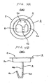
- [Figs. 4A and 4B] Fig. 4A is a plan view showing a condition in which the hook member is welded to the plate member, Fig. 4B is a side-elevational view showing this condition.
- [Fig. 5] A cross-sectional view explanatory of a first stage of the assembling of the spring assembly.
- [Fig. 6] A cross-sectional view explanatory of a second stage of the assembling of the spring assembly.
- [Fig. 7] A cross-sectional view explanatory of a third stage of the assembling of the spring assembly.
- [Fig. 8] A cross-sectional view explanatory of a fourth stage of the assembling of the spring assembly.
-
- 1
- compression coil spring (coil spring)
- 2
- retainer
- 3
- plate member
- 3a
- depressed central portion
- 4
- hook member
- 4a
- welding piece portion
- 4b
- pillar portion
- 4c
- turned-back portion
- 4d
- tapering shape
- 5
- slot (hole)
Claims (5)
- A spring assembly comprising: a coil spring; and a pair of retainers disposed respectively at opposite end portions of the coil spring, characterized in that: the retainer includes a plate member abutting against the end portion of the coil spring and depressed at a central portion thereof toward the inside of the coil spring, and a hook member fixed to the plate member so as to hold a free length of the coil spring shortened; the hook member includes a pillar portion depending from the plate member and extending into the inside of the coil spring, and a turned-back portion turned back at a distal end of the pillar portion so as to be engaged with the other turned-back portion; the turned-back portion is disposed at a region offset from a center axis of the coil spring in parallel relation thereto; and the pillar portion and a distal end of the turned-back portion are disposed along the center axis of the coil spring in opposed relation to each other.
- The spring assembly according to claim 1, characterized in that a hole is formed through the depressed central portion of the plate member.
- The spring assembly according to claim 2, characterized in that: the hole in the plate member is formed into a slot-shape; and the turned-back portion of the hook member extends in a direction of a shorter dimension of the hole.
- The spring assembly according to any one of claims 2 to 3, characterized in that: the hook member is formed by bending a metal plate; the turned-back portion is narrower in plate width than the pillar portion; and the width narrowing direction is such that the turned-back portion is narrowed in a direction to be disposed close to the center axis of the coil spring.
- The spring assembly according to claim 1, characterized in that: the plate member has a slot-shaped hole formed through a depressed central portion thereof; the turned-back portion of the hook member is extended in a direction of a shorter dimension of the hole; the hook member is formed by bending a metal plate; the turned-back portion is narrower in plate width than the pillar portion; and the width narrowing direction is such that the turned-back portion is narrowed in a direction to be disposed close to the center axis of the coil spring.
Applications Claiming Priority (2)
| Application Number | Priority Date | Filing Date | Title |
|---|---|---|---|
| JP2005104213 | 2005-03-31 | ||
| PCT/JP2006/305086 WO2006109392A1 (en) | 2005-03-31 | 2006-03-15 | Spring assembly |
Publications (3)
| Publication Number | Publication Date |
|---|---|
| EP1865219A1 true EP1865219A1 (en) | 2007-12-12 |
| EP1865219A4 EP1865219A4 (en) | 2009-07-22 |
| EP1865219B1 EP1865219B1 (en) | 2010-07-14 |
Family
ID=37086684
Family Applications (1)
| Application Number | Title | Priority Date | Filing Date |
|---|---|---|---|
| EP06729107A Expired - Fee Related EP1865219B1 (en) | 2005-03-31 | 2006-03-15 | Spring assembly |
Country Status (6)
| Country | Link |
|---|---|
| US (1) | US8181947B2 (en) |
| EP (1) | EP1865219B1 (en) |
| JP (1) | JP4897672B2 (en) |
| KR (1) | KR101222113B1 (en) |
| CN (1) | CN101156003B (en) |
| WO (1) | WO2006109392A1 (en) |
Cited By (1)
| Publication number | Priority date | Publication date | Assignee | Title |
|---|---|---|---|---|
| EP2667049A3 (en) * | 2012-05-22 | 2016-01-06 | Muhr und Bender KG | Assembly with helical spring and retention means, use of retention means and method for mounting helical springs |
Families Citing this family (11)
| Publication number | Priority date | Publication date | Assignee | Title |
|---|---|---|---|---|
| JP5501610B2 (en) * | 2008-12-25 | 2014-05-28 | 三菱重工業株式会社 | Turbine blade and gas turbine |
| JP5501609B2 (en) * | 2008-12-25 | 2014-05-28 | 三菱重工業株式会社 | Turbine blade and gas turbine |
| EP3054169B1 (en) | 2008-12-25 | 2019-02-20 | Mitsubishi Hitachi Power Systems, Ltd. | Stator blade assembly and gas turbine |
| US20100219572A1 (en) * | 2009-03-02 | 2010-09-02 | Gary Back | Independent Spring Cartridge |
| US8602950B2 (en) * | 2010-10-29 | 2013-12-10 | Balanced Body, Inc. | Coil spring connector loop handle |
| IN2013MU01449A (en) * | 2013-04-18 | 2015-04-17 | Rotex Manufacturers And Engineers Private Ltd | |
| CN112674538A (en) * | 2019-10-17 | 2021-04-20 | 厦门新技术集成有限公司 | Elastic module and elastic cushion for furniture |
| JP7379233B2 (en) | 2020-03-24 | 2023-11-14 | 日立Astemo株式会社 | Coil spring jig, coil spring manufacturing method, and coil spring testing method |
| CN113021264A (en) * | 2021-03-11 | 2021-06-25 | 蔚来汽车科技(安徽)有限公司 | Press-fitting holding device for spring |
| CN115251636A (en) * | 2021-04-29 | 2022-11-01 | 厦门新技术集成有限公司 | Sofa bed |
| EP4585106A1 (en) * | 2023-12-14 | 2025-07-16 | New-Tec Integration (Xiamen) Co., Ltd. | Spring module configured to be compressed for storage and elastic module, elastic mattress |
Family Cites Families (15)
| Publication number | Priority date | Publication date | Assignee | Title |
|---|---|---|---|---|
| US2406064A (en) * | 1943-12-04 | 1946-08-20 | Miner Inc W H | Shock absorber |
| US2558116A (en) * | 1948-06-23 | 1951-06-26 | Miner Inc W H | Friction shock absorber |
| DE7112269U (en) | 1971-03-31 | 1971-08-26 | Gerb William | Spring body to isolate machine vibrations |
| JPS604329A (en) | 1983-06-23 | 1985-01-10 | Nec Ic Microcomput Syst Ltd | Timing signal generating circuit |
| JPS61120854A (en) | 1984-11-19 | 1986-06-07 | Dainichi Seika Kogyo Kk | Electrically conductive resin composition |
| JPS61120854U (en) * | 1985-01-16 | 1986-07-30 | ||
| JPH0713541B2 (en) * | 1987-10-26 | 1995-02-15 | 松下電器産業株式会社 | Water amount control device for water heater |
| JP2830106B2 (en) | 1989-07-18 | 1998-12-02 | 日本電気株式会社 | Radio selective call receiver |
| JPH0349436U (en) * | 1989-09-22 | 1991-05-14 | ||
| JPH084314A (en) * | 1994-06-08 | 1996-01-09 | Tatsuo Tanaka | Stopper and stopper loaded protection cover |
| JP3497063B2 (en) * | 1997-06-30 | 2004-02-16 | アイシン・エィ・ダブリュ株式会社 | Spring assembly for accumulator and accumulator using the same |
| CN2369031Y (en) * | 1998-11-20 | 2000-03-15 | 台湾司普工业股份有限公司 | Spring retainer with compensating positioning effect |
| FR2824120B1 (en) | 2001-04-26 | 2003-08-08 | Bosch Gmbh Robert | PRE-STRESSED CAGE ELASTIC DEVICE AND APPLICATION |
| US7021610B2 (en) * | 2002-09-30 | 2006-04-04 | Barnes Group Inc. | Ring shaped spring device |
| DE20218768U1 (en) * | 2002-12-04 | 2003-04-10 | Stumpp & Schüle GmbH, 72660 Beuren | Spring assembly, comprising helical spring tensioned by device assembled of bolt and two conical holding elements |
-
2006
- 2006-03-15 JP JP2007512420A patent/JP4897672B2/en not_active Expired - Fee Related
- 2006-03-15 US US11/887,380 patent/US8181947B2/en not_active Expired - Fee Related
- 2006-03-15 WO PCT/JP2006/305086 patent/WO2006109392A1/en not_active Ceased
- 2006-03-15 EP EP06729107A patent/EP1865219B1/en not_active Expired - Fee Related
- 2006-03-15 KR KR1020077022141A patent/KR101222113B1/en not_active Expired - Fee Related
- 2006-03-15 CN CN2006800110842A patent/CN101156003B/en not_active Expired - Fee Related
Cited By (1)
| Publication number | Priority date | Publication date | Assignee | Title |
|---|---|---|---|---|
| EP2667049A3 (en) * | 2012-05-22 | 2016-01-06 | Muhr und Bender KG | Assembly with helical spring and retention means, use of retention means and method for mounting helical springs |
Also Published As
| Publication number | Publication date |
|---|---|
| CN101156003A (en) | 2008-04-02 |
| US20090134559A1 (en) | 2009-05-28 |
| KR101222113B1 (en) | 2013-01-15 |
| WO2006109392A1 (en) | 2006-10-19 |
| CN101156003B (en) | 2010-12-01 |
| EP1865219A4 (en) | 2009-07-22 |
| US8181947B2 (en) | 2012-05-22 |
| KR20070114785A (en) | 2007-12-04 |
| JPWO2006109392A1 (en) | 2008-10-09 |
| JP4897672B2 (en) | 2012-03-14 |
| EP1865219B1 (en) | 2010-07-14 |
Similar Documents
| Publication | Publication Date | Title |
|---|---|---|
| EP1865219B1 (en) | Spring assembly | |
| US8740199B2 (en) | Spring assembly and manufacturing method therefor | |
| EP0618086B1 (en) | Improvements in and relating to ring binder carrier rails | |
| EP1022503A1 (en) | Wire harness fixing clip | |
| EP3312055B1 (en) | Vehicle attachment component | |
| US20060091701A1 (en) | Frame assembly and method for forming the same | |
| US10561129B2 (en) | Fishing line guide, fishing rod including fishing line guide, and blank for fishing line guide | |
| EP2818342A1 (en) | Vehicle suspension arm | |
| US6435297B1 (en) | Vehicle component mounting assembly | |
| JP6617187B1 (en) | Movable connector | |
| JP5707164B2 (en) | Terminal bolt fastening structure and bracket | |
| JPWO2004061325A1 (en) | Closed end type coil spring with reduced initial deflection | |
| JP4360681B2 (en) | Reinforced concrete spacer | |
| JP5690305B2 (en) | Spring assembly | |
| JP6549795B2 (en) | Spring assembly and method of manufacturing the same | |
| JPH0669446U (en) | Spring assembly | |
| CN211731316U (en) | Mounting mechanism of safety limiting device and vehicle using same | |
| JP4714234B2 (en) | Cushion material | |
| JP3555545B2 (en) | Suspension equipment | |
| JP4283885B2 (en) | Hole cap | |
| JPH0139501B2 (en) | ||
| JP2001153136A (en) | Method of manufacturing spherical sliding bearing | |
| JPH1122771A (en) | Spring assembly for accumulator and accumulator using the same | |
| JP2016034230A (en) | Wire harness fixing structure | |
| JP2000312081A (en) | Bracket assembly mechanism |
Legal Events
| Date | Code | Title | Description |
|---|---|---|---|
| PUAI | Public reference made under article 153(3) epc to a published international application that has entered the european phase |
Free format text: ORIGINAL CODE: 0009012 |
|
| 17P | Request for examination filed |
Effective date: 20070928 |
|
| AK | Designated contracting states |
Kind code of ref document: A1 Designated state(s): FR GB |
|
| DAX | Request for extension of the european patent (deleted) | ||
| RBV | Designated contracting states (corrected) |
Designated state(s): FR GB |
|
| A4 | Supplementary search report drawn up and despatched |
Effective date: 20090624 |
|
| GRAP | Despatch of communication of intention to grant a patent |
Free format text: ORIGINAL CODE: EPIDOSNIGR1 |
|
| GRAS | Grant fee paid |
Free format text: ORIGINAL CODE: EPIDOSNIGR3 |
|
| GRAA | (expected) grant |
Free format text: ORIGINAL CODE: 0009210 |
|
| AK | Designated contracting states |
Kind code of ref document: B1 Designated state(s): FR GB |
|
| REG | Reference to a national code |
Ref country code: GB Ref legal event code: FG4D |
|
| PLBE | No opposition filed within time limit |
Free format text: ORIGINAL CODE: 0009261 |
|
| STAA | Information on the status of an ep patent application or granted ep patent |
Free format text: STATUS: NO OPPOSITION FILED WITHIN TIME LIMIT |
|
| PGFP | Annual fee paid to national office [announced via postgrant information from national office to epo] |
Ref country code: FR Payment date: 20110211 Year of fee payment: 6 |
|
| 26N | No opposition filed |
Effective date: 20110415 |
|
| PGFP | Annual fee paid to national office [announced via postgrant information from national office to epo] |
Ref country code: GB Payment date: 20110328 Year of fee payment: 6 |
|
| GBPC | Gb: european patent ceased through non-payment of renewal fee |
Effective date: 20120315 |
|
| REG | Reference to a national code |
Ref country code: FR Ref legal event code: ST Effective date: 20121130 |
|
| PG25 | Lapsed in a contracting state [announced via postgrant information from national office to epo] |
Ref country code: GB Free format text: LAPSE BECAUSE OF NON-PAYMENT OF DUE FEES Effective date: 20120315 Ref country code: FR Free format text: LAPSE BECAUSE OF NON-PAYMENT OF DUE FEES Effective date: 20120402 |