EP1865153A2 - Rotor disk and blade arrangement and method of assembly thereof - Google Patents
Rotor disk and blade arrangement and method of assembly thereof Download PDFInfo
- Publication number
- EP1865153A2 EP1865153A2 EP07252236A EP07252236A EP1865153A2 EP 1865153 A2 EP1865153 A2 EP 1865153A2 EP 07252236 A EP07252236 A EP 07252236A EP 07252236 A EP07252236 A EP 07252236A EP 1865153 A2 EP1865153 A2 EP 1865153A2
- Authority
- EP
- European Patent Office
- Prior art keywords
- blade
- blades
- slot
- disk
- seals
- Prior art date
- Legal status (The legal status is an assumption and is not a legal conclusion. Google has not performed a legal analysis and makes no representation as to the accuracy of the status listed.)
- Granted
Links
Images




Classifications
-
- F—MECHANICAL ENGINEERING; LIGHTING; HEATING; WEAPONS; BLASTING
- F01—MACHINES OR ENGINES IN GENERAL; ENGINE PLANTS IN GENERAL; STEAM ENGINES
- F01D—NON-POSITIVE DISPLACEMENT MACHINES OR ENGINES, e.g. STEAM TURBINES
- F01D5/00—Blades; Blade-carrying members; Heating, heat-insulating, cooling or antivibration means on the blades or the members
- F01D5/30—Fixing blades to rotors; Blade roots ; Blade spacers
- F01D5/3023—Fixing blades to rotors; Blade roots ; Blade spacers of radial insertion type, e.g. in individual recesses
- F01D5/303—Fixing blades to rotors; Blade roots ; Blade spacers of radial insertion type, e.g. in individual recesses in a circumferential slot
- F01D5/3038—Fixing blades to rotors; Blade roots ; Blade spacers of radial insertion type, e.g. in individual recesses in a circumferential slot the slot having inwardly directed abutment faces on both sides
-
- F—MECHANICAL ENGINEERING; LIGHTING; HEATING; WEAPONS; BLASTING
- F01—MACHINES OR ENGINES IN GENERAL; ENGINE PLANTS IN GENERAL; STEAM ENGINES
- F01D—NON-POSITIVE DISPLACEMENT MACHINES OR ENGINES, e.g. STEAM TURBINES
- F01D11/00—Preventing or minimising internal leakage of working-fluid, e.g. between stages
- F01D11/005—Sealing means between non relatively rotating elements
- F01D11/006—Sealing the gap between rotor blades or blades and rotor
-
- F—MECHANICAL ENGINEERING; LIGHTING; HEATING; WEAPONS; BLASTING
- F01—MACHINES OR ENGINES IN GENERAL; ENGINE PLANTS IN GENERAL; STEAM ENGINES
- F01D—NON-POSITIVE DISPLACEMENT MACHINES OR ENGINES, e.g. STEAM TURBINES
- F01D5/00—Blades; Blade-carrying members; Heating, heat-insulating, cooling or antivibration means on the blades or the members
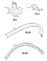
- F01D5/30—Fixing blades to rotors; Blade roots ; Blade spacers
- F01D5/32—Locking, e.g. by final locking blades or keys
-
- F—MECHANICAL ENGINEERING; LIGHTING; HEATING; WEAPONS; BLASTING
- F05—INDEXING SCHEMES RELATING TO ENGINES OR PUMPS IN VARIOUS SUBCLASSES OF CLASSES F01-F04
- F05D—INDEXING SCHEME FOR ASPECTS RELATING TO NON-POSITIVE-DISPLACEMENT MACHINES OR ENGINES, GAS-TURBINES OR JET-PROPULSION PLANTS
- F05D2230/00—Manufacture
- F05D2230/60—Assembly methods
-
- F—MECHANICAL ENGINEERING; LIGHTING; HEATING; WEAPONS; BLASTING
- F05—INDEXING SCHEMES RELATING TO ENGINES OR PUMPS IN VARIOUS SUBCLASSES OF CLASSES F01-F04
- F05D—INDEXING SCHEME FOR ASPECTS RELATING TO NON-POSITIVE-DISPLACEMENT MACHINES OR ENGINES, GAS-TURBINES OR JET-PROPULSION PLANTS
- F05D2240/00—Components
- F05D2240/55—Seals
-
- Y—GENERAL TAGGING OF NEW TECHNOLOGICAL DEVELOPMENTS; GENERAL TAGGING OF CROSS-SECTIONAL TECHNOLOGIES SPANNING OVER SEVERAL SECTIONS OF THE IPC; TECHNICAL SUBJECTS COVERED BY FORMER USPC CROSS-REFERENCE ART COLLECTIONS [XRACs] AND DIGESTS
- Y10—TECHNICAL SUBJECTS COVERED BY FORMER USPC
- Y10T—TECHNICAL SUBJECTS COVERED BY FORMER US CLASSIFICATION
- Y10T29/00—Metal working
- Y10T29/49—Method of mechanical manufacture
- Y10T29/49316—Impeller making
- Y10T29/4932—Turbomachine making
- Y10T29/49321—Assembling individual fluid flow interacting members, e.g., blades, vanes, buckets, on rotary support member
Definitions
- the invention generally relates an arrangement for loading and locking rotor blades for a rotor.
- Turbine engines include high and low pressure compressors to provide compressed air for combustion within the engine.
- Each compressor typically includes a rotor disk including multiple blades mounted on the disk. Seals are typically located between the disk and the blades to limit the recirculation of air.
- the disks typically have at least one loading slot for assembly of the blades into a blade slot within the disk and locking slot for preventing movement of the blades relative to the rotor disk once assembled.
- the rotor disk is repeatedly heated and cooled placing compressive and tensile forces on the outer portion of the disk.
- the cyclic loading from the thermal cycles fatigue the disk. Any areas of concentrated stress on the disk are prone to cracking as a result of the fatigue. Eliminating areas of stress concentration, such as the loading and locking slot, increases the durability of the rotor. Any loading arrangement must also prevent blade movement relative to the disk.
- An example compressor disk for a turbine engine includes an arrangement for loading blades on a compressor disk without requiring loading slots or locking slots.
- a typical compressor has multiple disks, with each disk including a plurality of blades mounted about a circumference.
- a lock assembly is inserted within a blade slot on the disk. At least one blade is assembled into the blade slot. A neck and a dovetail of the blade are inserted within the blade slot, then the blade is rotated 90-degrees. The dovetail interferes with the blade slot to prevent removal of the blade from the blade slot. Sliders seals are then inserted on each side of the blade slot, between the blade and the disk to limit air from entering the blade slot. Additional blades are assembled, until the end of the slider seals are reached.
- the additional blades are assembled such that the slider seals are located between the blades and the disk. Once the end of the slider seals are reached another lock assembly is inserted into the blade slot. The above process of inserting a blade, then slider seals, followed by additional blades to reach the end of the slider seals is repeated until all the blades have been assembled onto the disk.
- Slack is left between each of the adjacent slider seals to provide enough room for the last blade to be assembled.
- a spacer seal is placed across the blade slot at the location of each lock assembly to take up the slack.
- slider seals, blades and spacer seals are in place the lock assemblies can be moved from the released position, to a locked position.
- a set screw on each lock assembly is tightened to move the lock assembly into the lock position.
- the lock assemblies each include a rounded end of the set screw to interfit with a depression in the bottom of the blade slot to prevent rotation of the lock assembly.
- Figure 1 is a schematic view of a turbine engine 10. Air is pulled into the turbine engine 10 by a fan 12 and flows through a low pressure compressor 14 and a high pressure compressor 16. Fuel is mixed with the oxygen and combustion occurs within the combustor 18. Exhaust from combustion flows through a high pressure turbine 20 and a low pressure turbine 22 prior to leaving the engine through the exhaust nozzle 24.
- Figure 2 illustrates a portion of a cross-section of a typical compressor.
- the low pressure compressor 14 and the high pressure compressor 16 include multiple disks 26.
- Each disk 26 rotates about an axis A located along the centerline of the turbine engine 10.
- a plurality of blades 28 are mounted about the circumference of the disk 26.
- FIG. 4 illustrates an example blade 28 prior to assembly with the disk 26.
- the blade 28 includes a platform 30.
- a neck 32 extends from the platform 30 and a dovetail 34 extends from the neck 32.
- Figure 5 shows a portion of a cross-section of the disk 26 and blade 28 assembly through one of the blades 28.
- the disk 26 includes a blade slot 36.
- the blade slot 36 has a slot neck 38 that is narrower then a slot body 41.
- Slot rails 42 are located on the disk 26 on opposing sides of the blade slot 36.
- the neck 32 and dovetail 34 of the blade 28 are located within the blade slot 36.
- the dovetail 34 fits within the slot body 41 and the slot neck 38 interferes with the dovetail 34 to prevent removal of the blade 28 from the slot 36.
- Slider seals 40 are located between the blade 28 and the disk 26.
- a slider seal 40 is placed along the slot rail 42 on each side of the blade slot 36.
- the platform 30 contacts one portion of the slider seal 40 and the disk 26 contacts an opposing portion of the slider seal 40.
- the slider seals 40 limit air from entering between the blade 28 and the disk 26 into the blade slot 36.
- the slider seals 40 provide improved leakage protection over the prior art design and reduce the number of seals for each disk 26.
- the neck 32 and dovetail 34 are inserted within the blade slot 36 past a slot neck 38, as shown in Figure 6.
- the blade 28 is then rotated 90-degrees about a blade axis B, perpendicular to a slot axis of the blade slot 36 to arrive at the orientation shown in Figure 5.
- the dovetail 34 is prevented from movement past the slot neck 38, as shown.
- Pressure faces 44 on the dovetail 34 provide a surface for contacting the disk 26.
- Figure 7 illustrates blades 28 within the blade slot 36, where one blade 28a has been inserted and not yet rotated. Blades 28b are inserted within the blade slot 36 and rotated in position. The platforms 30 on the blades 28 are shaped to allow rotation of the blades 28, and fit together once rotated in position.
- a lock assembly 46 is inserted within the blade slot 36.
- the lock assembly 46 shown in Figure 9, includes a lock housing 48 and a set screw 50.
- the lock assembly 46 is assembled in a similar manner to the blade 28. That is, the lock assembly 46 is inserted past the slot neck 38 and rotated 90-degrees about the blade axis B, perpendicular to the slot axis. After the lock assembly 46 is rotated within the blade slot 36 the lock housing 48 interferes with and is prevented from movement past the slot neck 38.
- the lock housing 48 has pressure faces 49 to provide a surface for contacting the disk 26. During insertion of the lock assembly 46 and the blades 28 into the blade slot 36 the lock assembly 46 remains in a released position.
- the lock assembly 46 is assembled into the blade slot 36
- at least one blade 28c is assembled into the blade slot 36, as described above.
- Sliders seals 40 shown in Figure 10A, are then inserted on each side of the blade slot 36 between the blade 28 and the disk 26. Additional blades 28 are assembled onto the disk 26 such that the slider seals 40 are located between the blades 28 and the disk 26. Additional blades 28 are assembled, until the end of the slider seals 40 are reached.
- the slider seals 40 are configured as shown in Figure 10B.
- the disk 26 includes a groove to retain the sliders seals 40 on each side of the blade slot 36.
- the blades 28 also include a groove to assist in retention of the slider seals 40 against the blade 40 and to prevent ingress of air.
- each lock assembly 46 includes scallop 52 in the housing 48. The scallop 52 provides space for the dovetail 34 of the blades 28 to overlap the lock assembly 46 to provide additional slack during assembly of the final blade 28.
- Figure 11 illustrates the slack 53 that remains between sliders seals 40 after assembly of the blades 28.
- a spacer seal 54 shown in Figure 12, is placed between the slot rails 42 across the blade slot 36 at the location of each lock assembly 46.
- the body of the spacer seal 54 defines a through hole 56 to allow the housing 48 of the lock assembly 46 to extend through.
- the spacer seal 54 has projections extending in opposing directions from the seal body for locating next to the respective rails 42.
- the slack used to assemble the final blade 28 is taken up once all the spacer seals 54 are in place, as shown in Figures 13 and 14.
- the blades 28 located on each side of the lock assemblies 46 have a lock interfitting portion 58.
- the lock interfitting portion 58 has a complementary shape to the portion of lock housing 48 which contacts the blades 28. Any slack remaining is spread equally among each of the lock assemblies 46 and acts as a thermal gap to prevent the platforms 30 of the blades 28 from buckling during operation.
- the spacer seals 54 limit air from entering between the blades 28 and the disk 26 into the blade slot 36.
- the lock assemblies 46 can be moved from the released position, Figure 15, to the locked position.
- the set screw 50 on each lock assembly 46 is tightened moving the lock assembly 46 into the lock position shown in Figure 16.
- the lock assemblies 46 each include a first interlocking feature 60 and the blade slot 36 includes a second interlocking feature 62.
- the first interlocking feature 60 and the second interlocking feature 62 lock together to prevent rotation of the lock assembly 46.
- the first interlocking feature 60 is a rounded end of set screw 50 and the second interlocking feature 62 is a depression in the disk 26 at the bottom of the blade slot 36.
- the lock assemblies prevent circumferential motion of the blades 28, slider seals 40 and spacer seals 54.
- the example embodiment discloses arrangement of assembling blades onto a rotor disk for a compressor the arrangement may be used for any disk and blade assembly and is not limited to a compressor.
- the lock assemblies 46, slider seals 40, blades 28 and spacer seals 54 have a negligible difference in weight over prior art designs and decrease the number of seals required for each disk while reducing the stress concentrations on the disk 26 and blade 28 assembly.
Landscapes
- Engineering & Computer Science (AREA)
- Mechanical Engineering (AREA)
- General Engineering & Computer Science (AREA)
- Structures Of Non-Positive Displacement Pumps (AREA)
- Turbine Rotor Nozzle Sealing (AREA)
Abstract

Description
- The invention generally relates an arrangement for loading and locking rotor blades for a rotor.
- Turbine engines include high and low pressure compressors to provide compressed air for combustion within the engine. Each compressor typically includes a rotor disk including multiple blades mounted on the disk. Seals are typically located between the disk and the blades to limit the recirculation of air. The disks typically have at least one loading slot for assembly of the blades into a blade slot within the disk and locking slot for preventing movement of the blades relative to the rotor disk once assembled.
- During operation the rotor disk is repeatedly heated and cooled placing compressive and tensile forces on the outer portion of the disk. The cyclic loading from the thermal cycles fatigue the disk. Any areas of concentrated stress on the disk are prone to cracking as a result of the fatigue. Eliminating areas of stress concentration, such as the loading and locking slot, increases the durability of the rotor. Any loading arrangement must also prevent blade movement relative to the disk.
- An improved arrangement for loading and locking blades on a rotor disk without requiring a loading and locking slot is needed.
- An example compressor disk for a turbine engine according to this invention includes an arrangement for loading blades on a compressor disk without requiring loading slots or locking slots.
- A typical compressor has multiple disks, with each disk including a plurality of blades mounted about a circumference. In a disclosed embodiment of the invention, to begin assembly of the blades onto the disk a lock assembly is inserted within a blade slot on the disk. At least one blade is assembled into the blade slot. A neck and a dovetail of the blade are inserted within the blade slot, then the blade is rotated 90-degrees. The dovetail interferes with the blade slot to prevent removal of the blade from the blade slot. Sliders seals are then inserted on each side of the blade slot, between the blade and the disk to limit air from entering the blade slot. Additional blades are assembled, until the end of the slider seals are reached. The additional blades are assembled such that the slider seals are located between the blades and the disk. Once the end of the slider seals are reached another lock assembly is inserted into the blade slot. The above process of inserting a blade, then slider seals, followed by additional blades to reach the end of the slider seals is repeated until all the blades have been assembled onto the disk.
- Slack is left between each of the adjacent slider seals to provide enough room for the last blade to be assembled. After the last blade has been assembled a spacer seal is placed across the blade slot at the location of each lock assembly to take up the slack. After all of the lock assemblies, slider seals, blades and spacer seals are in place the lock assemblies can be moved from the released position, to a locked position. A set screw on each lock assembly is tightened to move the lock assembly into the lock position. The lock assemblies each include a rounded end of the set screw to interfit with a depression in the bottom of the blade slot to prevent rotation of the lock assembly.
- These and other features of the present invention can be best understood from the following specification and drawings, the following of which is a brief description.
-
- Figure 1 is a schematic view of an example turbine engine of the present invention;
- Figure 2 illustrates a portion of a cross-section of a typical compressor for the example turbine engine of the present invention;
- Figure 3 is an example compressor disk and blade assembly
- Figure 4 is a perspective view of an example blade for the example compressor;
- Figure 5 is a cross-sectional side elevation view of the example disk showing the example blade and a blade slot within the disk;
- Figure 6 is a cross-sectional side elevation view of the example disk showing the example blade inserted within the blade slot prior to rotation into an assembled position;
- Figure 7 is a radially inward view of a plurality of the example blades with the blade slot;
- Figure 8 illustrates a portion of the disk with a plurality of blades assembled on the disk;
- Figure 9 is a perspective view of an example lock assembly for the example compressor;
- Figure 10A is a perspective view of an example slider seal for the example compressor;
- Figure 10B is a perspective view of another example slider seal for the example compressor;
- Figure 11 illustrates a portion of the disk with a plurality of blades assembled on the disk showing slack between the plurality of blades prior to assembled of a spacer seal;
- Figure 12 is a perspective view of the example spacer seal for the example compressor;
- Figure 13 is a top view of a plurality of blades, the spacer seal, and the lock assembly assembled on the disk;
- Figure 14 is a side view of a plurality of blades, the spacer seal, and the lock assembly assembled on the disk
- Figure 15 is a cross-sectional side elevation view of the example disk showing the example lock assembly in a released position; and
- Figure 16 is a cross-sectional side elevation view of the example disk showing the example lock assembly in a locked position.
- Figure 1 is a schematic view of a
turbine engine 10. Air is pulled into theturbine engine 10 by afan 12 and flows through a low pressure compressor 14 and a high pressure compressor 16. Fuel is mixed with the oxygen and combustion occurs within thecombustor 18. Exhaust from combustion flows through ahigh pressure turbine 20 and alow pressure turbine 22 prior to leaving the engine through theexhaust nozzle 24. - Figure 2 illustrates a portion of a cross-section of a typical compressor. The low pressure compressor 14 and the high pressure compressor 16 include
multiple disks 26. Eachdisk 26 rotates about an axis A located along the centerline of theturbine engine 10. A plurality ofblades 28 are mounted about the circumference of thedisk 26. - Referring to Figure 3 an
example disk 26 havingblades 28 assembled thereon is shown. Figure 4 illustrates anexample blade 28 prior to assembly with thedisk 26. Theblade 28 includes aplatform 30. Aneck 32 extends from theplatform 30 and adovetail 34 extends from theneck 32. Figure 5 shows a portion of a cross-section of thedisk 26 andblade 28 assembly through one of theblades 28. Thedisk 26 includes ablade slot 36. Theblade slot 36 has aslot neck 38 that is narrower then aslot body 41.Slot rails 42 are located on thedisk 26 on opposing sides of theblade slot 36. Theneck 32 anddovetail 34 of theblade 28 are located within theblade slot 36. Thedovetail 34 fits within theslot body 41 and theslot neck 38 interferes with thedovetail 34 to prevent removal of theblade 28 from theslot 36. - Slider seals 40 are located between the
blade 28 and thedisk 26. Aslider seal 40 is placed along theslot rail 42 on each side of theblade slot 36. Theplatform 30 contacts one portion of theslider seal 40 and thedisk 26 contacts an opposing portion of theslider seal 40. The slider seals 40 limit air from entering between theblade 28 and thedisk 26 into theblade slot 36. The slider seals 40 provide improved leakage protection over the prior art design and reduce the number of seals for eachdisk 26. - To assemble the
blade 28 within theblade slot 36 theneck 32 anddovetail 34 are inserted within theblade slot 36 past aslot neck 38, as shown in Figure 6. Theblade 28 is then rotated 90-degrees about a blade axis B, perpendicular to a slot axis of theblade slot 36 to arrive at the orientation shown in Figure 5. Once rotated, thedovetail 34 is prevented from movement past theslot neck 38, as shown. Pressure faces 44 on thedovetail 34 provide a surface for contacting thedisk 26. - Figure 7 illustrates
blades 28 within theblade slot 36, where oneblade 28a has been inserted and not yet rotated.Blades 28b are inserted within theblade slot 36 and rotated in position. Theplatforms 30 on theblades 28 are shaped to allow rotation of theblades 28, and fit together once rotated in position. - Referring to Figures 8-10 an example assembly process of the
blades 28 onto thedisk 26 is illustrated. Alock assembly 46 is inserted within theblade slot 36. Thelock assembly 46, shown in Figure 9, includes alock housing 48 and aset screw 50. Thelock assembly 46 is assembled in a similar manner to theblade 28. That is, thelock assembly 46 is inserted past theslot neck 38 and rotated 90-degrees about the blade axis B, perpendicular to the slot axis. After thelock assembly 46 is rotated within theblade slot 36 thelock housing 48 interferes with and is prevented from movement past theslot neck 38. Thelock housing 48 has pressure faces 49 to provide a surface for contacting thedisk 26. During insertion of thelock assembly 46 and theblades 28 into theblade slot 36 thelock assembly 46 remains in a released position. - Once the
lock assembly 46 is assembled into theblade slot 36 at least oneblade 28c is assembled into theblade slot 36, as described above. Sliders seals 40, shown in Figure 10A, are then inserted on each side of theblade slot 36 between theblade 28 and thedisk 26.Additional blades 28 are assembled onto thedisk 26 such that the slider seals 40 are located between theblades 28 and thedisk 26.Additional blades 28 are assembled, until the end of the slider seals 40 are reached. Alternatively, the slider seals 40 are configured as shown in Figure 10B. In this example, thedisk 26 includes a groove to retain the sliders seals 40 on each side of theblade slot 36. Theblades 28 also include a groove to assist in retention of the slider seals 40 against theblade 40 and to prevent ingress of air. - Once the end of the slider seals 40 are reached another
lock assembly 46 is inserted into theblade slot 36. Thus, alock assembly 46 is located at each end of the slider seals 40. The above process of inserting ablade 28, then slider seals 40, followed byadditional blades 28 to reach the end of the slider seals 40 is repeated. Once again alock assembly 46 is inserted and the process repeated until all theblades 28 have been assembled onto thedisk 26. Upon completion of insertingblades 28 into theblade slot 36, alock assembly 46 is located between each circumferentially adjacent slider seals 40. In one example, there are eightlock assemblies 46 and eight sets of slider seals 40. The number oflock assemblies 46 and the number and length of the sliders seals 40 may vary. One skilled in the art would be able to determine the appropriate numbers and lengths ofblades 28, slider seals 40 andlock assemblies 46. - Slack is left between each of the circumferentially adjacent slider seals 40 to provide enough room for the
last blade 28 to be assembled. That is, to provide enough space to insert and then rotate thelast blade 28 into position, the already assembledblades 28 and the slider seals 40 may be all pushed together, eliminating the slack. After thelast blade 28 has been assembled some of slack remains between the each of the circumferentially adjacent slider seals 40. Additionally, eachlock assembly 46 includesscallop 52 in thehousing 48. Thescallop 52 provides space for thedovetail 34 of theblades 28 to overlap thelock assembly 46 to provide additional slack during assembly of thefinal blade 28. - Referring to Figures 11- 14, once all the
blades 28 have been assembled the slack used for assembly of thefinal blade 28 must be reduced to prevent theblades 28 from shifting and rotating during operation. Figure 11 illustrates the slack 53 that remains between sliders seals 40 after assembly of theblades 28. Aspacer seal 54, shown in Figure 12, is placed between the slot rails 42 across theblade slot 36 at the location of eachlock assembly 46. The body of thespacer seal 54 defines a throughhole 56 to allow thehousing 48 of thelock assembly 46 to extend through. As shown, thespacer seal 54 has projections extending in opposing directions from the seal body for locating next to the respective rails 42. The slack used to assemble thefinal blade 28 is taken up once all the spacer seals 54 are in place, as shown in Figures 13 and 14. To provide the most efficient fit possible, theblades 28 located on each side of thelock assemblies 46 have alock interfitting portion 58. Thelock interfitting portion 58 has a complementary shape to the portion oflock housing 48 which contacts theblades 28. Any slack remaining is spread equally among each of thelock assemblies 46 and acts as a thermal gap to prevent theplatforms 30 of theblades 28 from buckling during operation. In addition to reducing the slack, the spacer seals 54 limit air from entering between theblades 28 and thedisk 26 into theblade slot 36. - After all of the
lock assemblies 46, slider seals 40,blades 28 and spacer seals 54 are in place thelock assemblies 46 can be moved from the released position, Figure 15, to the locked position. Theset screw 50 on eachlock assembly 46 is tightened moving thelock assembly 46 into the lock position shown in Figure 16. Thelock assemblies 46 each include afirst interlocking feature 60 and theblade slot 36 includes asecond interlocking feature 62. When thelock assemblies 46 are in the lock position thefirst interlocking feature 60 and thesecond interlocking feature 62 lock together to prevent rotation of thelock assembly 46. In the example shown thefirst interlocking feature 60 is a rounded end ofset screw 50 and thesecond interlocking feature 62 is a depression in thedisk 26 at the bottom of theblade slot 36. The lock assemblies prevent circumferential motion of theblades 28, slider seals 40 and spacer seals 54. - Although the example embodiment discloses arrangement of assembling blades onto a rotor disk for a compressor the arrangement may be used for any disk and blade assembly and is not limited to a compressor. The
lock assemblies 46, slider seals 40,blades 28 and spacer seals 54 have a negligible difference in weight over prior art designs and decrease the number of seals required for each disk while reducing the stress concentrations on thedisk 26 andblade 28 assembly. - Although a preferred embodiment of this invention has been disclosed, a worker of ordinary skill in this art would recognize that certain modifications would come within the scope of this invention. For that reason, the following claims should be studied to determine the true scope and content of this invention.
Claims (23)
- A compressor (14) comprising:a rotor disk (26) defining a blade slot (36);a plurality of blades (28) each having a portion located within the blade slot (36);a plurality of slider seals (40) located between the plurality of blades (28) and the rotor disk (26);a plurality of spacer seals (54) located between the plurality of slider seals (40); anda plurality of lock assemblies (46), each lock assembly (46) associated with one of the plurality of spacer seals (54).
- The compressor of claim 1, wherein each of the plurality of blades (28) comprises a platform (30) having a neck (32) extending from the platform (30) and a dovetail (34) extending from the neck (32).
- The compressor of claim 2, wherein the neck (32) and the dovetail (34) for each of the plurality of blades (28) is located within the blade slot (36).
- The compressor of any preceding claim, wherein a slot rail (42) is located on each side of the blade slot (36) and each of the plurality of slider seals (40) are associated with one of the slot rails (42).
- The compressor of claim 4, wherein each of the plurality of slider seals (40) are located between the blades (28) and the slot rails (42).
- The compressor of claim 4 or 5, wherein each of the plurality of spacer seals (40) extend across the blade slot (36) between the slot rails (42).
- The compressor of any preceding claim, wherein each of the plurality of lock assemblies (46) comprises a housing (48) and a set screw (50) movable between a load position and a lock position, and the lock assembly (46) is located substantially within the blade slot (36).
- The compressor of claim 7, wherein each of the plurality of spacer seals (54) includes a through hole (56) and the housing (48) of the lock assembly (46) extends through the through hole (56) and contacts each adjacent blades (28) when the lock assembly (46) is in the lock position:
- The compressor of claim 7 or 8, wherein the set screw (50) includes a first interlocking feature (60) and the blade slot (36) includes a second interlocking feature (62) and the first interlocking feature (60) locks with the second interlocking feature (62) when the lock assembly (46) is in the lock position.
- A turbine engine component comprising:a disk (26) including a pair of slot rails (42) located on opposing sides of a blade slot (36), and mounted for rotation about an axis of the turbine engine;a first plurality of blades (28) each having a portion located within the blade slot (36), wherein a first pair of slider seals (40) are located between the first plurality of blades (28) and the slot rails (42);a second plurality of blades (28) each having a portion located within the blade slot (36), wherein a second pair of slider seals (40) are located between the second plurality of blades (28) and the slot rails (42);a first spacer seal (54) located between the first pair of spacer seals (40) and the second pair of spacer seals (40); anda first lock assembly (46) located in the blade slot (36) and associated with the first spacer seal (54).
- The component of claim 10, wherein each of the first plurality of blades (28) and each of the second plurality of blades (28) comprises a platform (30) and wherein the platforms (30) of circumferentially adjacent blades (28) are in contact with one another.
- The component of claim 10 or 11, wherein the first spacer seal (54) extends across the blade slot (36) between the disk rails (42).
- The component of claim 10, 11 or 12, wherein the first lock assembly (46) comprises a housing (48) and a set screw (50).
- The component of claim 13, wherein the first spacer seal (54) includes a through hole (56) and the housing (48) of the first lock assembly (46) extends through the through hole (58) and contacts one blade (28) from the first plurality of blades (28) and one blade (28) from the second plurality of blades (28) when the first lock assembly (46) is in a lock position.
- The component of any of claims 10 to 14, further comprising:a third plurality of blades (28) each having a portion located within the blade slot (36), wherein a third pair of slider seals (40) are located between the third plurality of blades (28) and the disk rails (42);a fourth plurality of blades (28) each having a portion located within the blade slot (36), wherein a fourth pair of slider seals (40) are located between the fourth plurality of blades (28) and the disk rails (42);a second spacer seal (54) located between the second pair of slider seals (40) and the third pair of slider seals (40), a third spacer seal (54) located between the third pair of slider seals (40) and the fourth pair of slider seals (40), a fourth spacer seal (54) located between the fourth pair of slider seals (40) and the first pair of slider seals (40); anda second lock assembly (46) located in the blade slot (36) and associated with the second spacer seal (54), a third lock assembly (46) located in the blade slot (36) and associated with the third spacer seal (54), and a fourth lock assembly (46) located in the blade slot (36) and associated with the fourth spacer seal (40).
- The component of any of claims 10 to 15, wherein the disk (26) comprises a compressor disk.
- A method of assembling a compressor (14) comprising comprising:a) placing a first lock assembly (46) in a blade slot (36) located in a rotor disk (26);b) inserting a first blade (28) in the blade slot (36) adjacent to the first lock assembly (46);c) placing a first slider seal (40) between the first blade (28) and a first wall of the blade slot (36) and placing a second slider seal (40) between the first blade (28) and an opposing wall of the blade slot (36);d) inserting a second blade (28) in the blade slot (36) such that the first slider seal (40) and the second slider seal (40) are located between the second blade (28) and the rotor disk (26);e) repeating said steps a) through d) until all of the plurality of blades (28) are inserted in the blade slot (38);f) placing a spacer seal (54) across the blade slot (36) at each lock assembly (46) location; andg) locking the lock assembly (46) to prevent circumferential motion of the blades (28), slider seals (40) and spacer seals (54).
- The method of claim 17, wherein said step d) includes locating the second blade (28) such that a platform (30) on the first blade (28) is contacting a platform (30) of the second blade (28).
- The method of claim 17 or 18, wherein said step e) includes repeating said step d) until ends of the first and second slider seals (40) are reached then repeating steps a) through c) such that a lock assembly (46) is located between each circumferentially adjacent first and second slider seals (40).
- The method of claim 17, 18 or 19, wherein said step g) includes tightening a set screw (50) in the lock assembly (46) to move a lock assembly housing (48) through a hole (56) in the associated spacer seal (54) to contact each of the adjacent blades (28).
- A component for a disk and blade assembly comprising:a lock housing (48) defining at least one indentation for receiving a portion of a blade (28);a lock portion (50) supported by the lock housing (48) and moveable relative to the lock housing (48) between a lock position and a released position to retain at least one blade (28) from movement relative to a disk (26) when in the lock position.
- The component of claim 21, wherein the lock portion comprises a set screw (50).
- A component for a disk and blade assembly comprising:a seal (54) having a body defining a space for receiving a portion of a lock housing (48);a first projection extending from the body in a first direction, wherein the first projection is for locating next to a first disk rail (42); anda second projection extending from the body in a second direction, opposing the first direction, wherein the second projection is for locating next to a second disk rail (42), opposing the first disk rail (42), such that the seal (54) is positionable across a blade slot (36) between the first disk rail (42) and the second disk rail (42).
Applications Claiming Priority (1)
| Application Number | Priority Date | Filing Date | Title |
|---|---|---|---|
| US11/446,724 US8608446B2 (en) | 2006-06-05 | 2006-06-05 | Rotor disk and blade arrangement |
Publications (3)
| Publication Number | Publication Date |
|---|---|
| EP1865153A2 true EP1865153A2 (en) | 2007-12-12 |
| EP1865153A3 EP1865153A3 (en) | 2011-01-12 |
| EP1865153B1 EP1865153B1 (en) | 2019-05-01 |
Family
ID=38212258
Family Applications (1)
| Application Number | Title | Priority Date | Filing Date |
|---|---|---|---|
| EP07252236.0A Active EP1865153B1 (en) | 2006-06-05 | 2007-06-01 | Compressor and method of assembly thereof |
Country Status (3)
| Country | Link |
|---|---|
| US (1) | US8608446B2 (en) |
| EP (1) | EP1865153B1 (en) |
| JP (1) | JP2007321764A (en) |
Cited By (4)
| Publication number | Priority date | Publication date | Assignee | Title |
|---|---|---|---|---|
| EP2441921A1 (en) * | 2010-10-12 | 2012-04-18 | Siemens Aktiengesellschaft | Turbomachine rotor blade roots with adjusting protrusions |
| CH703997A1 (en) * | 2010-10-27 | 2012-04-30 | Alstom Technology Ltd | Blade assembly, in particular vane. |
| US8851852B2 (en) | 2009-12-07 | 2014-10-07 | Alstom Technology Ltd. | Turbine assembly |
| EP3851634A1 (en) * | 2020-01-20 | 2021-07-21 | Raytheon Technologies Corporation | Seal element for sealing a joint between a rotor blade and a rotor disk of a turbine engine |
Families Citing this family (19)
| Publication number | Priority date | Publication date | Assignee | Title |
|---|---|---|---|---|
| US9057278B2 (en) * | 2012-08-22 | 2015-06-16 | General Electric Company | Turbine bucket including an integral rotation controlling feature |
| US9650902B2 (en) * | 2013-01-11 | 2017-05-16 | United Technologies Corporation | Integral fan blade wear pad and platform seal |
| US9512732B2 (en) | 2013-10-16 | 2016-12-06 | General Electric Company | Locking spacer assembly inserted between rotor blades |
| US9518471B2 (en) | 2013-10-16 | 2016-12-13 | General Electric Company | Locking spacer assembly |
| US9464531B2 (en) | 2013-10-16 | 2016-10-11 | General Electric Company | Locking spacer assembly |
| US9341071B2 (en) | 2013-10-16 | 2016-05-17 | General Electric Company | Locking spacer assembly |
| US9416670B2 (en) | 2013-10-16 | 2016-08-16 | General Electric Company | Locking spacer assembly |
| US10125619B2 (en) | 2015-11-19 | 2018-11-13 | General Electric Company | Rotor assembly for use in a turbofan engine and method of assembling |
| GB2554650B (en) * | 2016-09-30 | 2019-02-06 | Rolls Royce Plc | Side seal for a gas turbine engine |
| US9682756B1 (en) | 2016-10-17 | 2017-06-20 | General Electric Company | System for composite marine propellers |
| US11052982B2 (en) | 2016-10-17 | 2021-07-06 | General Electric Company | Apparatus for dovetail chord relief for marine propeller |
| US10633067B2 (en) | 2016-10-17 | 2020-04-28 | General Electric Company | Method and system for improving flow characteristics in marine propellers |
| US10689073B2 (en) | 2016-10-17 | 2020-06-23 | General Electric Company | Apparatus and system for marine propeller blade dovetail stress reduction |
| US10703452B2 (en) | 2016-10-17 | 2020-07-07 | General Electric Company | Apparatus and system for propeller blade aft retention |
| US10486785B2 (en) | 2016-10-17 | 2019-11-26 | General Electric Company | Propeller assembly and method of assembling |
| CN109209994B (en) * | 2017-06-29 | 2020-06-05 | 中国航发商用航空发动机有限责任公司 | Rotor blade locking device |
| US11156111B2 (en) | 2018-08-31 | 2021-10-26 | Rolls-Royce Corporation | Pinned platform for blade with circumferential attachment |
| US10641111B2 (en) | 2018-08-31 | 2020-05-05 | Rolls-Royce Corporation | Turbine blade assembly with ceramic matrix composite components |
| US10633986B2 (en) | 2018-08-31 | 2020-04-28 | Rolls-Roye Corporation | Platform with axial attachment for blade with circumferential attachment |
Citations (3)
| Publication number | Priority date | Publication date | Assignee | Title |
|---|---|---|---|---|
| EP0081436A1 (en) | 1981-12-09 | 1983-06-15 | Societe Nationale D'etude Et De Construction De Moteurs D'aviation, "S.N.E.C.M.A." | Compressor or turbine rotor, the wheel of which supports the hammer-type foot blades and method of assembling such a rotor |
| GB2156908A (en) | 1984-03-30 | 1985-10-16 | Rolls Royce | Bladed rotor assembly for gas turbine engine |
| FR2664944A1 (en) | 1990-07-18 | 1992-01-24 | Snecma | Compressor formed particularly of diffusers in the shape of a ring and method for mounting this compressor |
Family Cites Families (13)
| Publication number | Priority date | Publication date | Assignee | Title |
|---|---|---|---|---|
| US1303004A (en) * | 1919-05-06 | l alois | ||
| US1687891A (en) * | 1924-09-08 | 1928-10-16 | Westinghouse Electric & Mfg Co | Blade fastening |
| US2315631A (en) * | 1942-02-14 | 1943-04-06 | Westinghouse Electric & Mfg Co | Turbine blade locking apparatus |
| US2631004A (en) * | 1948-07-09 | 1953-03-10 | United Specialties Co | Turbine rotor |
| CH357414A (en) | 1957-03-05 | 1961-10-15 | Oerlikon Maschf | Axial flow machine |
| CH494341A (en) | 1968-07-26 | 1970-07-31 | Sulzer Ag | Rotor for turbo machinery |
| DE2027861C3 (en) * | 1970-06-06 | 1973-12-06 | Motoren- Und Turbinen-Union Muenchen Gmbh, 8000 Muenchen | Disc-shaped impeller for high-speed axial turbines |
| GB2171150B (en) | 1985-02-12 | 1989-07-26 | Rolls Royce Plc | Bladed rotor assembly for a turbomachine |
| US4875830A (en) | 1985-07-18 | 1989-10-24 | United Technologies Corporation | Flanged ladder seal |
| USH1258H (en) * | 1992-09-16 | 1993-12-07 | The United States Of America As Represented By The Secretary Of The Air Force | Blade lock screw |
| FR2810366B1 (en) * | 2000-06-15 | 2002-10-11 | Snecma Moteurs | DEVICE FOR LOCKING BLADES WITH HAMMER FASTENERS ON A DISC |
| FR2832455B1 (en) * | 2001-11-22 | 2004-04-02 | Snecma Moteurs | DEVICE FOR LOCKING BLADES IN A GROOVE OF A DISC |
| US8206116B2 (en) * | 2005-07-14 | 2012-06-26 | United Technologies Corporation | Method for loading and locking tangential rotor blades and blade design |
-
2006
- 2006-06-05 US US11/446,724 patent/US8608446B2/en active Active
-
2007
- 2007-06-01 EP EP07252236.0A patent/EP1865153B1/en active Active
- 2007-06-04 JP JP2007147579A patent/JP2007321764A/en active Pending
Patent Citations (3)
| Publication number | Priority date | Publication date | Assignee | Title |
|---|---|---|---|---|
| EP0081436A1 (en) | 1981-12-09 | 1983-06-15 | Societe Nationale D'etude Et De Construction De Moteurs D'aviation, "S.N.E.C.M.A." | Compressor or turbine rotor, the wheel of which supports the hammer-type foot blades and method of assembling such a rotor |
| GB2156908A (en) | 1984-03-30 | 1985-10-16 | Rolls Royce | Bladed rotor assembly for gas turbine engine |
| FR2664944A1 (en) | 1990-07-18 | 1992-01-24 | Snecma | Compressor formed particularly of diffusers in the shape of a ring and method for mounting this compressor |
Cited By (9)
| Publication number | Priority date | Publication date | Assignee | Title |
|---|---|---|---|---|
| US8851852B2 (en) | 2009-12-07 | 2014-10-07 | Alstom Technology Ltd. | Turbine assembly |
| EP2441921A1 (en) * | 2010-10-12 | 2012-04-18 | Siemens Aktiengesellschaft | Turbomachine rotor blade roots with adjusting protrusions |
| WO2012048957A1 (en) | 2010-10-12 | 2012-04-19 | Siemens Aktiengesellschaft | Turbomachine rotor with blade roots with adjusting protrusions |
| RU2559957C2 (en) * | 2010-10-12 | 2015-08-20 | Сименс Акциенгезелльшафт | Turbomachine rotor and method of its assembly |
| US9664054B2 (en) | 2010-10-12 | 2017-05-30 | Siemens Aktiengesellschaft | Turbomachine rotor with blade roots with adjusting protrusions |
| CH703997A1 (en) * | 2010-10-27 | 2012-04-30 | Alstom Technology Ltd | Blade assembly, in particular vane. |
| EP2447474A1 (en) | 2010-10-27 | 2012-05-02 | Alstom Technology Ltd | Blade arrangement, especially stator blade arrangement |
| US8979497B2 (en) | 2010-10-27 | 2015-03-17 | Alstom Technology Ltd. | Blade arrangement, especially stator blade arrangement |
| EP3851634A1 (en) * | 2020-01-20 | 2021-07-21 | Raytheon Technologies Corporation | Seal element for sealing a joint between a rotor blade and a rotor disk of a turbine engine |
Also Published As
| Publication number | Publication date |
|---|---|
| US20070280831A1 (en) | 2007-12-06 |
| JP2007321764A (en) | 2007-12-13 |
| EP1865153B1 (en) | 2019-05-01 |
| EP1865153A3 (en) | 2011-01-12 |
| US8608446B2 (en) | 2013-12-17 |
Similar Documents
| Publication | Publication Date | Title |
|---|---|---|
| EP1865153B1 (en) | Compressor and method of assembly thereof | |
| US8206116B2 (en) | Method for loading and locking tangential rotor blades and blade design | |
| US8769817B2 (en) | Seal assembly retention method | |
| US5584654A (en) | Gas turbine engine fan stator | |
| US8757966B2 (en) | Stationary vane assembly for a turbine engine having a reduced weight, and turbine engine comprising at least one such stationary vane assembly | |
| US8894370B2 (en) | Turbine blade retention system and method | |
| US20060222502A1 (en) | Locking spacer assembly for a turbine engine | |
| US8210819B2 (en) | Airfoil structure shim | |
| KR102170572B1 (en) | Turbomachine rotor assembly and method | |
| US10865652B2 (en) | Method and device for piston seal anti-rotation | |
| US7708529B2 (en) | Rotor of a turbo engine, e.g., a gas turbine rotor | |
| US8573940B2 (en) | Interlocking knife edge seals | |
| US6722848B1 (en) | Turbine nozzle retention apparatus at the carrier horizontal joint face | |
| US8066489B2 (en) | Aerofoil assembly | |
| EP2578910B1 (en) | Strip seals | |
| US9890653B2 (en) | Gas turbine bucket shanks with seal pins | |
| EP3795869A1 (en) | Seal assembly with anti-rotation lock | |
| US20250179935A1 (en) | Turbine shroud assembly with pinned turbine shroud and vane with pin retainer | |
| US11519286B2 (en) | Sealing assembly and sealing member therefor with spline seal retention | |
| EP4039942B1 (en) | Sealing assembly and sealing member therefor with spline seal retention | |
| KR20240169707A (en) | Locking spacer assembly and method for installing the locking spacer assembly |
Legal Events
| Date | Code | Title | Description |
|---|---|---|---|
| PUAI | Public reference made under article 153(3) epc to a published international application that has entered the european phase |
Free format text: ORIGINAL CODE: 0009012 |
|
| AK | Designated contracting states |
Kind code of ref document: A2 Designated state(s): AT BE BG CH CY CZ DE DK EE ES FI FR GB GR HU IE IS IT LI LT LU LV MC MT NL PL PT RO SE SI SK TR |
|
| AX | Request for extension of the european patent |
Extension state: AL BA HR MK YU |
|
| PUAL | Search report despatched |
Free format text: ORIGINAL CODE: 0009013 |
|
| AK | Designated contracting states |
Kind code of ref document: A3 Designated state(s): AT BE BG CH CY CZ DE DK EE ES FI FR GB GR HU IE IS IT LI LT LU LV MC MT NL PL PT RO SE SI SK TR |
|
| AX | Request for extension of the european patent |
Extension state: AL BA HR MK RS |
|
| 17P | Request for examination filed |
Effective date: 20110712 |
|
| AKX | Designation fees paid |
Designated state(s): DE GB |
|
| 17Q | First examination report despatched |
Effective date: 20141008 |
|
| RAP1 | Party data changed (applicant data changed or rights of an application transferred) |
Owner name: UNITED TECHNOLOGIES CORPORATION |
|
| STAA | Information on the status of an ep patent application or granted ep patent |
Free format text: STATUS: EXAMINATION IS IN PROGRESS |
|
| GRAP | Despatch of communication of intention to grant a patent |
Free format text: ORIGINAL CODE: EPIDOSNIGR1 |
|
| STAA | Information on the status of an ep patent application or granted ep patent |
Free format text: STATUS: GRANT OF PATENT IS INTENDED |
|
| INTG | Intention to grant announced |
Effective date: 20181031 |
|
| GRAS | Grant fee paid |
Free format text: ORIGINAL CODE: EPIDOSNIGR3 |
|
| GRAJ | Information related to disapproval of communication of intention to grant by the applicant or resumption of examination proceedings by the epo deleted |
Free format text: ORIGINAL CODE: EPIDOSDIGR1 |
|
| GRAL | Information related to payment of fee for publishing/printing deleted |
Free format text: ORIGINAL CODE: EPIDOSDIGR3 |
|
| STAA | Information on the status of an ep patent application or granted ep patent |
Free format text: STATUS: EXAMINATION IS IN PROGRESS |
|
| GRAJ | Information related to disapproval of communication of intention to grant by the applicant or resumption of examination proceedings by the epo deleted |
Free format text: ORIGINAL CODE: EPIDOSDIGR1 |
|
| GRAR | Information related to intention to grant a patent recorded |
Free format text: ORIGINAL CODE: EPIDOSNIGR71 |
|
| STAA | Information on the status of an ep patent application or granted ep patent |
Free format text: STATUS: GRANT OF PATENT IS INTENDED |
|
| GRAJ | Information related to disapproval of communication of intention to grant by the applicant or resumption of examination proceedings by the epo deleted |
Free format text: ORIGINAL CODE: EPIDOSDIGR1 |
|
| GRAP | Despatch of communication of intention to grant a patent |
Free format text: ORIGINAL CODE: EPIDOSNIGR1 |
|
| GRAA | (expected) grant |
Free format text: ORIGINAL CODE: 0009210 |
|
| STAA | Information on the status of an ep patent application or granted ep patent |
Free format text: STATUS: THE PATENT HAS BEEN GRANTED |
|
| REG | Reference to a national code |
Ref country code: DE Ref legal event code: R081 Ref document number: 602007058233 Country of ref document: DE Owner name: RAYTHEON TECHNOLOGIES CORPORATION (N.D.GES.D.S, US Free format text: FORMER OWNER: UNITED TECHNOLOGIES CORP., HARTFORD, CONN., US |
|
| INTC | Intention to grant announced (deleted) | ||
| INTG | Intention to grant announced |
Effective date: 20190320 |
|
| AK | Designated contracting states |
Kind code of ref document: B1 Designated state(s): DE GB |
|
| INTG | Intention to grant announced |
Effective date: 20190320 |
|
| REG | Reference to a national code |
Ref country code: GB Ref legal event code: FG4D |
|
| REG | Reference to a national code |
Ref country code: DE Ref legal event code: R096 Ref document number: 602007058233 Country of ref document: DE |
|
| REG | Reference to a national code |
Ref country code: DE Ref legal event code: R097 Ref document number: 602007058233 Country of ref document: DE |
|
| PLBE | No opposition filed within time limit |
Free format text: ORIGINAL CODE: 0009261 |
|
| STAA | Information on the status of an ep patent application or granted ep patent |
Free format text: STATUS: NO OPPOSITION FILED WITHIN TIME LIMIT |
|
| 26N | No opposition filed |
Effective date: 20200204 |
|
| REG | Reference to a national code |
Ref country code: DE Ref legal event code: R081 Ref document number: 602007058233 Country of ref document: DE Owner name: RAYTHEON TECHNOLOGIES CORPORATION (N.D.GES.D.S, US Free format text: FORMER OWNER: UNITED TECHNOLOGIES CORPORATION, FARMINGTON, CONN., US Ref country code: DE Ref legal event code: R081 Ref document number: 602007058233 Country of ref document: DE Owner name: RTX CORPORATION (N.D.GES.D. STAATES DELAWARE),, US Free format text: FORMER OWNER: UNITED TECHNOLOGIES CORPORATION, FARMINGTON, CONN., US |
|
| P01 | Opt-out of the competence of the unified patent court (upc) registered |
Effective date: 20230519 |
|
| PGFP | Annual fee paid to national office [announced via postgrant information from national office to epo] |
Ref country code: DE Payment date: 20250520 Year of fee payment: 19 |
|
| PGFP | Annual fee paid to national office [announced via postgrant information from national office to epo] |
Ref country code: GB Payment date: 20250520 Year of fee payment: 19 |
|
| REG | Reference to a national code |
Ref country code: DE Ref legal event code: R081 Ref document number: 602007058233 Country of ref document: DE Owner name: RTX CORPORATION (N.D.GES.D. STAATES DELAWARE),, US Free format text: FORMER OWNER: RAYTHEON TECHNOLOGIES CORPORATION (N.D.GES.D.STAATES DELAWARE), ARLINGTON, VA, US |