EP1865149A2 - Serpentine cooling circuit and method for cooling tip shroud - Google Patents
Serpentine cooling circuit and method for cooling tip shroud Download PDFInfo
- Publication number
- EP1865149A2 EP1865149A2 EP07109482A EP07109482A EP1865149A2 EP 1865149 A2 EP1865149 A2 EP 1865149A2 EP 07109482 A EP07109482 A EP 07109482A EP 07109482 A EP07109482 A EP 07109482A EP 1865149 A2 EP1865149 A2 EP 1865149A2
- Authority
- EP
- European Patent Office
- Prior art keywords
- shroud
- cooling
- airfoil
- serpentine
- cooling passage
- Prior art date
- Legal status (The legal status is an assumption and is not a legal conclusion. Google has not performed a legal analysis and makes no representation as to the accuracy of the status listed.)
- Granted
Links
- 238000001816 cooling Methods 0.000 title claims abstract description 66
- 238000000034 method Methods 0.000 title claims description 10
- 239000012809 cooling fluid Substances 0.000 claims description 9
- 238000004891 communication Methods 0.000 claims description 6
- 230000005465 channeling Effects 0.000 claims 1
- 238000005192 partition Methods 0.000 claims 1
- 230000002093 peripheral effect Effects 0.000 claims 1
- 239000002826 coolant Substances 0.000 description 12
- 239000007789 gas Substances 0.000 description 10
- 230000008901 benefit Effects 0.000 description 4
- WYTGDNHDOZPMIW-RCBQFDQVSA-N alstonine Natural products C1=CC2=C3C=CC=CC3=NC2=C2N1C[C@H]1[C@H](C)OC=C(C(=O)OC)[C@H]1C2 WYTGDNHDOZPMIW-RCBQFDQVSA-N 0.000 description 3
- 238000004519 manufacturing process Methods 0.000 description 3
- 238000012546 transfer Methods 0.000 description 3
- 238000005266 casting Methods 0.000 description 2
- 238000013461 design Methods 0.000 description 2
- 238000005495 investment casting Methods 0.000 description 2
- 239000002184 metal Substances 0.000 description 2
- 241000237509 Patinopecten sp. Species 0.000 description 1
- 238000007599 discharging Methods 0.000 description 1
- 238000009826 distribution Methods 0.000 description 1
- 238000005516 engineering process Methods 0.000 description 1
- 239000000446 fuel Substances 0.000 description 1
- 238000012986 modification Methods 0.000 description 1
- 230000004048 modification Effects 0.000 description 1
- 238000005457 optimization Methods 0.000 description 1
- 230000000452 restraining effect Effects 0.000 description 1
- 235000020637 scallop Nutrition 0.000 description 1
- 239000007787 solid Substances 0.000 description 1
- 238000003466 welding Methods 0.000 description 1
Images

Classifications
-
- F—MECHANICAL ENGINEERING; LIGHTING; HEATING; WEAPONS; BLASTING
- F01—MACHINES OR ENGINES IN GENERAL; ENGINE PLANTS IN GENERAL; STEAM ENGINES
- F01D—NON-POSITIVE DISPLACEMENT MACHINES OR ENGINES, e.g. STEAM TURBINES
- F01D5/00—Blades; Blade-carrying members; Heating, heat-insulating, cooling or antivibration means on the blades or the members
- F01D5/12—Blades
- F01D5/14—Form or construction
- F01D5/18—Hollow blades, i.e. blades with cooling or heating channels or cavities; Heating, heat-insulating or cooling means on blades
- F01D5/187—Convection cooling
-
- F—MECHANICAL ENGINEERING; LIGHTING; HEATING; WEAPONS; BLASTING
- F01—MACHINES OR ENGINES IN GENERAL; ENGINE PLANTS IN GENERAL; STEAM ENGINES
- F01D—NON-POSITIVE DISPLACEMENT MACHINES OR ENGINES, e.g. STEAM TURBINES
- F01D5/00—Blades; Blade-carrying members; Heating, heat-insulating, cooling or antivibration means on the blades or the members
- F01D5/02—Blade-carrying members, e.g. rotors
- F01D5/08—Heating, heat-insulating or cooling means
-
- F—MECHANICAL ENGINEERING; LIGHTING; HEATING; WEAPONS; BLASTING
- F01—MACHINES OR ENGINES IN GENERAL; ENGINE PLANTS IN GENERAL; STEAM ENGINES
- F01D—NON-POSITIVE DISPLACEMENT MACHINES OR ENGINES, e.g. STEAM TURBINES
- F01D25/00—Component parts, details, or accessories, not provided for in, or of interest apart from, other groups
- F01D25/08—Cooling; Heating; Heat-insulation
- F01D25/12—Cooling
-
- F—MECHANICAL ENGINEERING; LIGHTING; HEATING; WEAPONS; BLASTING
- F01—MACHINES OR ENGINES IN GENERAL; ENGINE PLANTS IN GENERAL; STEAM ENGINES
- F01D—NON-POSITIVE DISPLACEMENT MACHINES OR ENGINES, e.g. STEAM TURBINES
- F01D5/00—Blades; Blade-carrying members; Heating, heat-insulating, cooling or antivibration means on the blades or the members
- F01D5/12—Blades
- F01D5/22—Blade-to-blade connections, e.g. for damping vibrations
- F01D5/225—Blade-to-blade connections, e.g. for damping vibrations by shrouding
-
- F—MECHANICAL ENGINEERING; LIGHTING; HEATING; WEAPONS; BLASTING
- F05—INDEXING SCHEMES RELATING TO ENGINES OR PUMPS IN VARIOUS SUBCLASSES OF CLASSES F01-F04
- F05B—INDEXING SCHEME RELATING TO WIND, SPRING, WEIGHT, INERTIA OR LIKE MOTORS, TO MACHINES OR ENGINES FOR LIQUIDS COVERED BY SUBCLASSES F03B, F03D AND F03G
- F05B2240/00—Components
- F05B2240/20—Rotors
- F05B2240/33—Shrouds which are part of or which are rotating with the rotor
-
- F—MECHANICAL ENGINEERING; LIGHTING; HEATING; WEAPONS; BLASTING
- F05—INDEXING SCHEMES RELATING TO ENGINES OR PUMPS IN VARIOUS SUBCLASSES OF CLASSES F01-F04
- F05D—INDEXING SCHEME FOR ASPECTS RELATING TO NON-POSITIVE-DISPLACEMENT MACHINES OR ENGINES, GAS-TURBINES OR JET-PROPULSION PLANTS
- F05D2240/00—Components
- F05D2240/80—Platforms for stationary or moving blades
- F05D2240/81—Cooled platforms
-
- F—MECHANICAL ENGINEERING; LIGHTING; HEATING; WEAPONS; BLASTING
- F05—INDEXING SCHEMES RELATING TO ENGINES OR PUMPS IN VARIOUS SUBCLASSES OF CLASSES F01-F04
- F05D—INDEXING SCHEME FOR ASPECTS RELATING TO NON-POSITIVE-DISPLACEMENT MACHINES OR ENGINES, GAS-TURBINES OR JET-PROPULSION PLANTS
- F05D2250/00—Geometry
- F05D2250/10—Two-dimensional
- F05D2250/18—Two-dimensional patterned
- F05D2250/183—Two-dimensional patterned zigzag
-
- F—MECHANICAL ENGINEERING; LIGHTING; HEATING; WEAPONS; BLASTING
- F05—INDEXING SCHEMES RELATING TO ENGINES OR PUMPS IN VARIOUS SUBCLASSES OF CLASSES F01-F04
- F05D—INDEXING SCHEME FOR ASPECTS RELATING TO NON-POSITIVE-DISPLACEMENT MACHINES OR ENGINES, GAS-TURBINES OR JET-PROPULSION PLANTS
- F05D2250/00—Geometry
- F05D2250/10—Two-dimensional
- F05D2250/18—Two-dimensional patterned
- F05D2250/184—Two-dimensional patterned sinusoidal
-
- F—MECHANICAL ENGINEERING; LIGHTING; HEATING; WEAPONS; BLASTING
- F05—INDEXING SCHEMES RELATING TO ENGINES OR PUMPS IN VARIOUS SUBCLASSES OF CLASSES F01-F04
- F05D—INDEXING SCHEME FOR ASPECTS RELATING TO NON-POSITIVE-DISPLACEMENT MACHINES OR ENGINES, GAS-TURBINES OR JET-PROPULSION PLANTS
- F05D2250/00—Geometry
- F05D2250/10—Two-dimensional
- F05D2250/18—Two-dimensional patterned
- F05D2250/185—Two-dimensional patterned serpentine-like
-
- F—MECHANICAL ENGINEERING; LIGHTING; HEATING; WEAPONS; BLASTING
- F05—INDEXING SCHEMES RELATING TO ENGINES OR PUMPS IN VARIOUS SUBCLASSES OF CLASSES F01-F04
- F05D—INDEXING SCHEME FOR ASPECTS RELATING TO NON-POSITIVE-DISPLACEMENT MACHINES OR ENGINES, GAS-TURBINES OR JET-PROPULSION PLANTS
- F05D2260/00—Function
- F05D2260/20—Heat transfer, e.g. cooling
- F05D2260/221—Improvement of heat transfer
- F05D2260/2214—Improvement of heat transfer by increasing the heat transfer surface
- F05D2260/22141—Improvement of heat transfer by increasing the heat transfer surface using fins or ribs
-
- Y—GENERAL TAGGING OF NEW TECHNOLOGICAL DEVELOPMENTS; GENERAL TAGGING OF CROSS-SECTIONAL TECHNOLOGIES SPANNING OVER SEVERAL SECTIONS OF THE IPC; TECHNICAL SUBJECTS COVERED BY FORMER USPC CROSS-REFERENCE ART COLLECTIONS [XRACs] AND DIGESTS
- Y02—TECHNOLOGIES OR APPLICATIONS FOR MITIGATION OR ADAPTATION AGAINST CLIMATE CHANGE
- Y02T—CLIMATE CHANGE MITIGATION TECHNOLOGIES RELATED TO TRANSPORTATION
- Y02T50/00—Aeronautics or air transport
- Y02T50/60—Efficient propulsion technologies, e.g. for aircraft
Definitions
- the present invention relates generally to a blade for a turbine, e.g. aircraft engine, gas turbine, steam turbine, etc. More specifically, the present invention relates to the cooling of a turbine blade tip shroud. As a non-limiting example the invention and its background are described with reference to a gas turbine.
- a gas turbine is typically comprised of a compressor section that produces compressed air. Fuel is mixed with a portion of the compressed air and burned in one or more combustors, thereby producing hot compressed gas. The hot compressed gas is expanded in a turbine section to produce rotating shaft power.
- the turbine section is typically comprised of a plurality of alternating rows of stationary vanes (nozzles) and rotating blades (buckets). Each of the rotating blades has an airfoil portion and a root portion by which it is affixed to a rotor.
- blade cooling is accomplished by extracting a portion of the compressed air from the compressor and directing it to the turbine section, thereby bypassing the combustors. After introduction into the turbine section, this cooling air flows through passages formed in the airfoil portions of the blades. Often, radial passages are provided that discharge the cooling air radially outwardly at the blade tip.
- integral tip shrouds are used on the radially outer end of the blade to create an outer surface of the passage through which the hot gases must pass. Having the shroud as a part of the airfoil results in an increase in performance for the engine. As such, it is desirable for the entire outer surface to be covered by the tip shrouds.
- integral shrouds on rotating airfoils are highly stressed parts due to the mechanical forces applied via the rotational speed. The high temperature environment coupled with the high stresses makes it a challenge to design a shroud that will effectively perform over the entire useful life of the remainder of the blade. Two methods for resolving this challenge are to reduce the stress and/or reduce the temperature.
- a common method for reducing the stress is to remove a portion of the overhanging shroud (scallop the shroud), thus reducing the load applied. Reducing the tip shroud coverage, however, results in a detriment to engine performance.
- cooling air discharging at the blade tip flows over the radially outward facing surface of the shroud so as to provide a measure of film cooling.
- the present invention proposes to more effectively cool the blade tip shroud by providing for serpentine cooling thereof, primarily at but not limited to the fillets between the airfoil and the tip shroud.
- the invention further provides a method of cooling a tip shroud using such a serpentine circuit.
- each turbine blade 10 is comprised of an airfoil portion 12 and a root portion 14.
- the airfoil portion has a leading edge and a trailing edge.
- a generally concave surface and a generally convex suction surface extend between the leading and trailing edges on opposing sides of the airfoil.
- the blade root 14 is comprised of a shank 16 and a dovetail 18 to engage a corresponding dovetail groove on the rotor to secure the blade to the rotor.
- a shroud 20 is formed at the tip of the airfoil 12 and extends outwardly from the airfoil.
- the shroud thus has radially inward and radially outward facing surfaces and is exposed to the hot compressed gas flowing through the turbine section.
- Each shroud has bearing surfaces 22,24 over which it contacts a shroud of an adjacent blade thereby restraining blade vibration.
- a baffle 26 typically extends radially outward from the shroud to prevent leakage of hot gas around the respective blade row.
- a plurality of cooling air passages extend radially outwardly through the blade into the blade tip.
- serpentine passages are defined in the airfoil.
- the cooling air passages (whether radial or serpentine), conventionally terminate at air discharge holes 28 that allow the cooling air to discharge at the radially outward surface of the shroud. Although nine holes 28 are illustrated in FIGURE 2, more or fewer passages may be utilized.
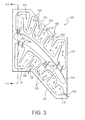
- At least one serpentine circuit 130,131,132,133,231,233 is formed inside the tip shroud 120,220.
- air is taken into the blade, e.g., near the dovetail or shank area, flows through the shank and into and along the airfoil toward the tip shroud 120.
- a center chamber 134,234 is defined at the radial outer end of the airfoil 112,212 as a cooling fluid (air) reservoir for distribution through the shroud via the serpentine circuit(s).
- the plurality of passages extending along the airfoil may be respectively coupled to respective serpentine circuits within the shroud.
- the cooling air flows from the coolant reservoir or the respective coolant passage(s) to and through the serpentine circuit(s).
- the serpentine circuits 130,131,132,133,231,233 may each have any number of back and forth passes where the coolant flows in a first direction and then turns and flows in another direction, which may be a diametrically opposite (180°) direction or at a lesser angle, such as 150°(30°) or 120°(60°).
- the cooling circuits in the tip shroud may have additional features inside the circuit such as turbulators or turning vanes, schematically shown at 136 to enhance heat transfer or reduce pressure loss.
- the serpentine circuits are disposed primarily in the plane of the tip shroud. Once the coolant has completed its traverse through the respective circuit, it exits through one or more apertures 128 from the shroud to the main gas path.
- FIGURE 3 (in conjunction with FIGURES 4 and 5) schematically illustrates an embodiment with four serpentine circuits 130,131,132,133,231,233.
- the cooling medium flows from the airfoil into a tip shroud center chamber 134,234 which in turn supplies each of the four serpentine circuits.
- the center chamber is not required and the cooling medium can flow directly from airfoil cooling passage(s) into any or all of the tip shroud serpentine circuits.
- any number of center chambers could be used to supply any number of tip shroud serpentine circuits.
- a manufacturing convenience for blades that have airfoil cooling features that are formed after the blade is cast is that the center chamber can be left open at the time of casting and sealed after the airfoil cooling features are formed, e.g., with an end plate/cap or simply by welding the opening shut without any end cap.
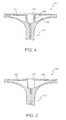
- FIGURES 4 and 5 schematically illustrate two example cross-sections of the tip shroud of FIGURE 3.
- holes 138 are provided for connecting the serpentine circuits to the center chamber.
- the holes may be used not only to simply connect the serpentine circuits to the center chamber, but may also be adapted to meter flow into the respective circuits.
- the center chamber is completely open to the serpentine circuits.
- Both the FIGURE 4 and FIGURE 5 embodiments may be defined by a common investment-casting core.
- the core may print out the top or edge of the part at the various points along the length of the serpentine circuit.
- Core print outs 140 would serve to strengthen the core during the process of forming the blade. They may be sealed after casting or left open, in which case they become bleed holes. Bleed holes would provide local convective cooling to the adjacent area but would reduce the amount of coolant downstream in the serpentine circuit which may or may not be an advantage from a heat transfer perspective.
- the shroud serpentine circuits may be connected to the airfoil serpentine circuits.
- the serpentine circuits of the shroud can be connected to a center chamber or directly to the radial cooling holes. Forming a center chamber is conducive to manufacturing the radial cooling holes, but must be sealed prior to use.
- the serpentine circuits of the shroud may be cast in the part and radial holes drilled through the part to intersect those serpentine circuits. The top of the drilled through hole may then be sealed to force the coolant to pass through the serpentine circuit(s) before exiting the shroud.
- the spent cooling air exiting from the serpentine circuits may be advantageously located for further cooling optimization.
- the exit(s) to the serpentine circuit(s) may be disposed to cool the interface 122,124 between adjacent blade tip shrouds.
- a benefit of a serpentine cooled tip shroud according to example embodiments of the invention is that the weight of the blade is reduced accordingly.
- the velocity of the shroud coolant air should be kept reasonably high. For blades with low coolant flows and hollow tip shrouds, this is primarily accomplished by reducing the size of the channels in which the coolant flows. This results in more shroud metal or a smaller overall shroud. In general more shroud metal results in greater bucket weight, whereas a smaller overall shroud, i.e. scalloped shroud, results in lower engine performance.
- Providing serpentine circuit(s) as described herein allows a small amount of cooling air to pass through relatively small channels a number of times. This maintains coolant velocity while increasing the volume of air inside the tip shroud and reducing blade weight as compared to a solid tip having a similar amount of scalloping.
- serpentine circuit(s) that are integral to the part, i.e., cast in, provides significant benefits to the structural integrity of the part. Indeed, no process would be required to create a joint between the tip shroud and the main body of the blade. Such joints are difficult to inspect to ensure mechanical integrity for the useful life of the balance of the blade.
Abstract
Description
- The present invention relates generally to a blade for a turbine, e.g. aircraft engine, gas turbine, steam turbine, etc. More specifically, the present invention relates to the cooling of a turbine blade tip shroud. As a non-limiting example the invention and its background are described with reference to a gas turbine.
- A gas turbine is typically comprised of a compressor section that produces compressed air. Fuel is mixed with a portion of the compressed air and burned in one or more combustors, thereby producing hot compressed gas. The hot compressed gas is expanded in a turbine section to produce rotating shaft power. The turbine section is typically comprised of a plurality of alternating rows of stationary vanes (nozzles) and rotating blades (buckets). Each of the rotating blades has an airfoil portion and a root portion by which it is affixed to a rotor.
- Since the blades are exposed to the hot gas discharged from the combustors, cooling methods are required to obtain a useful design life cycle. Traditionally, blade cooling is accomplished by extracting a portion of the compressed air from the compressor and directing it to the turbine section, thereby bypassing the combustors. After introduction into the turbine section, this cooling air flows through passages formed in the airfoil portions of the blades. Often, radial passages are provided that discharge the cooling air radially outwardly at the blade tip.
- On many rotating airfoils, integral tip shrouds are used on the radially outer end of the blade to create an outer surface of the passage through which the hot gases must pass. Having the shroud as a part of the airfoil results in an increase in performance for the engine. As such, it is desirable for the entire outer surface to be covered by the tip shrouds. However, integral shrouds on rotating airfoils are highly stressed parts due to the mechanical forces applied via the rotational speed. The high temperature environment coupled with the high stresses makes it a challenge to design a shroud that will effectively perform over the entire useful life of the remainder of the blade. Two methods for resolving this challenge are to reduce the stress and/or reduce the temperature.
- A common method for reducing the stress is to remove a portion of the overhanging shroud (scallop the shroud), thus reducing the load applied. Reducing the tip shroud coverage, however, results in a detriment to engine performance. In addition or in the alternative, cooling air discharging at the blade tip flows over the radially outward facing surface of the shroud so as to provide a measure of film cooling.
- According to one aspect, the present invention proposes to more effectively cool the blade tip shroud by providing for serpentine cooling thereof, primarily at but not limited to the fillets between the airfoil and the tip shroud. In another aspect, the invention further provides a method of cooling a tip shroud using such a serpentine circuit.
- Thus the invention may be embodied in a turbine blade comprising:
- a root portion for fixing said blade to a turbine rotor;
- an airfoil portion extending longitudinally from said root;
- at least one airfoil cooling passage extending through said airfoil, said airfoil cooling passage having an inlet for receiving a flow of cooling fluid;
- a shroud projecting outwardly from said airfoil and having a radially inward facing surface and a radially outward facing surface; and
- at least one serpentine cooling passage defined to extend back and forth through at least a portion of said shroud, said serpentine cooling passage being in flow communication with said airfoil cooling passage so as to receive cooling fluid therefrom and including at least one outlet opening for spent cooling fluid to exit the shroud,
- whereby at least a first portion of said cooling fluid received by said airfoil cooling passage through said inlet thereof flows into and through said serpentine cooling passage, and exits through said at least one outlet opening.
- Various objects and advantages of this invention will be more completely understood and appreciated by careful study of the following more detailed description of the presently preferred example embodiments of the invention taken in conjunction with the accompanying drawings, in which:
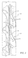
- FIGURE 1 is a schematic perspective view of a conventional turbine blade with tip shroud;
- FIGURE 2 is a schematic plan view of conventional tip shrouds, illustrating shroud scalloping;
- FIGURE 3 is a schematic plan view of an embodiment of a serpentine cooled tip shroud embodying the invention;
- FIGURE 4 is a schematic cross-sectional view of an example embodiment of the invention taken along line 4-4 of FIGURE 3; and
- FIGURE 5 is a schematic cross-sectional view of another example embodiment of the invention taken along line 4-4 of FIGURE 3.
- A typical blade with cooling passages exiting at the blade tip to flow over the tip shroud is schematically illustrated in FIGURE 1. As schematically illustrated therein, each
turbine blade 10 is comprised of anairfoil portion 12 and aroot portion 14. The airfoil portion has a leading edge and a trailing edge. A generally concave surface and a generally convex suction surface extend between the leading and trailing edges on opposing sides of the airfoil. In the illustrated example, theblade root 14 is comprised of ashank 16 and adovetail 18 to engage a corresponding dovetail groove on the rotor to secure the blade to the rotor. - As shown in FIGURES 1 and 2, a
shroud 20 is formed at the tip of theairfoil 12 and extends outwardly from the airfoil. The shroud thus has radially inward and radially outward facing surfaces and is exposed to the hot compressed gas flowing through the turbine section. Each shroud has bearingsurfaces baffle 26 typically extends radially outward from the shroud to prevent leakage of hot gas around the respective blade row. In some conventional bucket blade structures, a plurality of cooling air passages extend radially outwardly through the blade into the blade tip. In other conventional bucket blade structures serpentine passages are defined in the airfoil. As shown in FIGURE 2, the cooling air passages (whether radial or serpentine), conventionally terminate atair discharge holes 28 that allow the cooling air to discharge at the radially outward surface of the shroud. Although nineholes 28 are illustrated in FIGURE 2, more or fewer passages may be utilized. - Referring to FIGURES 3-5, to provide more complete and effective cooling of the tip shroud, in an example embodiment of the invention, at least one serpentine circuit 130,131,132,133,231,233 is formed inside the tip shroud 120,220. In a conventional manner, air is taken into the blade, e.g., near the dovetail or shank area, flows through the shank and into and along the airfoil toward the
tip shroud 120. In the illustrated examples, a center chamber 134,234 is defined at the radial outer end of the airfoil 112,212 as a cooling fluid (air) reservoir for distribution through the shroud via the serpentine circuit(s). As an alternative, the plurality of passages extending along the airfoil may be respectively coupled to respective serpentine circuits within the shroud. - The cooling air flows from the coolant reservoir or the respective coolant passage(s) to and through the serpentine circuit(s). The serpentine circuits 130,131,132,133,231,233 may each have any number of back and forth passes where the coolant flows in a first direction and then turns and flows in another direction, which may be a diametrically opposite (180°) direction or at a lesser angle, such as 150°(30°) or 120°(60°). The cooling circuits in the tip shroud may have additional features inside the circuit such as turbulators or turning vanes, schematically shown at 136 to enhance heat transfer or reduce pressure loss. The serpentine circuits are disposed primarily in the plane of the tip shroud. Once the coolant has completed its traverse through the respective circuit, it exits through one or
more apertures 128 from the shroud to the main gas path. - FIGURE 3 (in conjunction with FIGURES 4 and 5) schematically illustrates an embodiment with four serpentine circuits 130,131,132,133,231,233. Thus, as illustrated therein, the cooling medium flows from the airfoil into a tip shroud center chamber 134,234 which in turn supplies each of the four serpentine circuits. As noted above, the center chamber is not required and the cooling medium can flow directly from airfoil cooling passage(s) into any or all of the tip shroud serpentine circuits. Additionally, any number of center chambers could be used to supply any number of tip shroud serpentine circuits. However, a manufacturing convenience for blades that have airfoil cooling features that are formed after the blade is cast, is that the center chamber can be left open at the time of casting and sealed after the airfoil cooling features are formed, e.g., with an end plate/cap or simply by welding the opening shut without any end cap.
- FIGURES 4 and 5 schematically illustrate two example cross-sections of the tip shroud of FIGURE 3. In FIGURE 4,
holes 138 are provided for connecting the serpentine circuits to the center chamber. The holes may be used not only to simply connect the serpentine circuits to the center chamber, but may also be adapted to meter flow into the respective circuits. In the alternative configuration of FIGURE 5, the center chamber is completely open to the serpentine circuits. Both the FIGURE 4 and FIGURE 5 embodiments may be defined by a common investment-casting core. - Features may be added to the serpentine circuit(s) to ease manufacture during the investment-casting phase of forming the blade. For example, the core may print out the top or edge of the part at the various points along the length of the serpentine circuit.
Core print outs 140 would serve to strengthen the core during the process of forming the blade. They may be sealed after casting or left open, in which case they become bleed holes. Bleed holes would provide local convective cooling to the adjacent area but would reduce the amount of coolant downstream in the serpentine circuit which may or may not be an advantage from a heat transfer perspective. - In the event the airfoil incorporates serpentine circuits, the shroud serpentine circuits may be connected to the airfoil serpentine circuits. In a blade without serpentine cooling, for example, one that uses radial drilled cooling holes as mentioned above, the serpentine circuits of the shroud can be connected to a center chamber or directly to the radial cooling holes. Forming a center chamber is conducive to manufacturing the radial cooling holes, but must be sealed prior to use. Alternatively, the serpentine circuits of the shroud may be cast in the part and radial holes drilled through the part to intersect those serpentine circuits. The top of the drilled through hole may then be sealed to force the coolant to pass through the serpentine circuit(s) before exiting the shroud. As an additional feature, the spent cooling air exiting from the serpentine circuits may be advantageously located for further cooling optimization. For example, the exit(s) to the serpentine circuit(s) may be disposed to cool the interface 122,124 between adjacent blade tip shrouds.
- A benefit of a serpentine cooled tip shroud according to example embodiments of the invention is that the weight of the blade is reduced accordingly. In this regard, for heat transfer purposes, the velocity of the shroud coolant air should be kept reasonably high. For blades with low coolant flows and hollow tip shrouds, this is primarily accomplished by reducing the size of the channels in which the coolant flows. This results in more shroud metal or a smaller overall shroud. In general more shroud metal results in greater bucket weight, whereas a smaller overall shroud, i.e. scalloped shroud, results in lower engine performance. Providing serpentine circuit(s) as described herein allows a small amount of cooling air to pass through relatively small channels a number of times. This maintains coolant velocity while increasing the volume of air inside the tip shroud and reducing blade weight as compared to a solid tip having a similar amount of scalloping.
- Finally, providing serpentine circuit(s) that are integral to the part, i.e., cast in, provides significant benefits to the structural integrity of the part. Indeed, no process would be required to create a joint between the tip shroud and the main body of the blade. Such joints are difficult to inspect to ensure mechanical integrity for the useful life of the balance of the blade.
- While the invention has been described in connection with what is presently considered to be the most practical and preferred embodiment, it is to be understood that the invention is not to be limited to the disclosed embodiment, but on the contrary, is intended to cover various modifications and equivalent arrangements included within the spirit and scope of the appended claims. For example, while reference has been made in particular to the cooling of a tip shroud, the technology disclosed herein could be used on a shroud that is not located at the tip of the blade. In this regard, some blades have shrouds about mid-length of the airfoil that connect it to its adjacent blade, and the cooling passages described hereinabove could be incorporated therein.
Claims (10)
- A turbine blade comprising:a root portion (14) for fixing said blade to a turbine rotor;an airfoil portion (112, 212) extending longitudinally from said root;at least one airfoil cooling passage extending through said airfoil, said airfoil cooling passage having an inlet for receiving a flow of cooling fluid;a shroud (120, 220) projecting outwardly from said airfoil and having a radially inward facing surface and a radially outward facing surface; andat least one serpentine cooling passage (130,131,132,133,231,233) defined to extend back and forth through at least a portion of said shroud, said serpentine cooling passage being in flow communication with said airfoil cooling passage so as to receive cooling fluid therefrom and including at least one outlet opening (128) for spent cooling fluid to exit the shroud,whereby at least a first portion of said cooling fluid received by said airfoil cooling passage through said inlet thereof flows into and through said serpentine cooling passage, and exits through said at least one outlet opening.
- A turbine blade as in claim 1, wherein said shroud has a bearing surface (122, 124) for engaging a shroud of an adjacent blade, and at least one said outlet opening (128) is disposed adjacent said bearing surface.
- A turbine blade as in claim 1 or claim 2, wherein said shroud includes at least one center cooling chamber (134, 234), said center cooling chamber being in flow communication with said at least one airfoil cooling passage and being in flow communication with said at least one serpentine cooling passage.
- A turbine blade as in claim 3, wherein said center cooling chamber is in flow communication with said at least one serpentine cooling passage via at least one flow opening 138 in a partition wall therebetween.
- A turbine blade as in claim 3 or claim 4, wherein said center cooling chamber is in open flow communication with said at least one serpentine cooling passage.
- A turbine blade as in any preceding claim, wherein there are a plurality of serpentine cooling passages defined in said shroud.
- A turbine rotor having a row of turbine blades as set forth in any preceding claim.
- A method of cooling a gas turbine airfoil (112, 212) having an associated substantially planar shroud (120, 220) extending in a plane substantially perpendicular to the airfoil, the method comprising:a) providing at least one airfoil cooling passage in said airfoil;b) providing at least one serpentine cooling passage (130,131,132,133,231,233) in said shroud that extends back and forth through at least a portion of said shroud;c) supplying cooling air to said at least one airfoil cooling passage;d) channeling said cooling air to said at least one serpentine cooling passage in said shroud; ande) passing said cooling air through said at least one serpentine cooling passage and out through said shroud.
- The method of claim 8 wherein step e) is carried out by providing at least one cooling air exhaust hole (128) in said tip shroud, opening at a peripheral edge of the shroud.
- The method of claim 8 or claim 9, wherein the at least one serpentine cooling passage is investment cast when the airfoil is formed.
Applications Claiming Priority (1)
| Application Number | Priority Date | Filing Date | Title |
|---|---|---|---|
| US11/447,910 US7686581B2 (en) | 2006-06-07 | 2006-06-07 | Serpentine cooling circuit and method for cooling tip shroud |
Publications (3)
| Publication Number | Publication Date |
|---|---|
| EP1865149A2 true EP1865149A2 (en) | 2007-12-12 |
| EP1865149A3 EP1865149A3 (en) | 2011-06-08 |
| EP1865149B1 EP1865149B1 (en) | 2016-05-25 |
Family
ID=38288485
Family Applications (1)
| Application Number | Title | Priority Date | Filing Date |
|---|---|---|---|
| EP07109482.5A Active EP1865149B1 (en) | 2006-06-07 | 2007-06-04 | Serpentine cooling circuit and method for cooling tip shroud |
Country Status (4)
| Country | Link |
|---|---|
| US (1) | US7686581B2 (en) |
| EP (1) | EP1865149B1 (en) |
| JP (1) | JP5185569B2 (en) |
| KR (1) | KR101378252B1 (en) |
Cited By (15)
| Publication number | Priority date | Publication date | Assignee | Title |
|---|---|---|---|---|
| EP2211019A2 (en) * | 2009-01-26 | 2010-07-28 | Rolls-Royce PLC | Rotor blade |
| US8096767B1 (en) * | 2009-02-04 | 2012-01-17 | Florida Turbine Technologies, Inc. | Turbine blade with serpentine cooling circuit formed within the tip shroud |
| US8133032B2 (en) | 2007-12-19 | 2012-03-13 | Rolls-Royce, Plc | Rotor blades |
| EP2213838A3 (en) * | 2009-01-30 | 2013-08-21 | United Technologies Corporation | Cooled turbine blade shroud |
| US9062561B2 (en) | 2010-09-29 | 2015-06-23 | Rolls-Royce Plc | Endwall component for a turbine stage of a gas turbine engine |
| EP2885519A4 (en) * | 2012-08-15 | 2016-06-08 | United Technologies Corp | Platform cooling circuit for a gas turbine engine component |
| EP3156612A1 (en) * | 2015-10-12 | 2017-04-19 | United Technologies Corporation | Gas turbine engine components, blade outer air seal assemblies, and blade outer air seal segments thereof |
| CN107435561A (en) * | 2016-04-14 | 2017-12-05 | 通用电气公司 | System for the sealing guide rail of the sophisticated integral shroud of cooling turbine bucket |
| CN110863864A (en) * | 2019-12-11 | 2020-03-06 | 沈阳航空航天大学 | Turbine blade with transversely-meandering alternately-shrinking and-expanding short channels inside |
| CN111677556A (en) * | 2015-12-07 | 2020-09-18 | 通用电气公司 | Fillet optimization for turbine airfoils |
| EP3916200A1 (en) * | 2020-05-15 | 2021-12-01 | General Electric Company | Systems and methods for cooling an endwall in a rotary machine |
| DE102008055590B4 (en) | 2008-01-10 | 2022-04-28 | General Electric Co. | Turbine blade shroud |
| DE102009003327B4 (en) | 2008-01-10 | 2023-03-02 | General Electric Company | Turbine blade tip shroud |
| DE102009003318B4 (en) | 2008-01-10 | 2024-01-11 | General Electric Company | Turbine blade tip shroud |
| DE102008003412B4 (en) | 2007-01-12 | 2024-02-29 | General Electric Company | Turbine blade cover installed in a turbine rotor with impingement cooling and cooling methods |
Families Citing this family (58)
| Publication number | Priority date | Publication date | Assignee | Title |
|---|---|---|---|---|
| US8057177B2 (en) * | 2008-01-10 | 2011-11-15 | General Electric Company | Turbine blade tip shroud |
| US20090180894A1 (en) * | 2008-01-10 | 2009-07-16 | General Electric Company | Turbine blade tip shroud |
| GB2461502B (en) * | 2008-06-30 | 2010-05-19 | Rolls Royce Plc | An aerofoil |
| US8096772B2 (en) * | 2009-03-20 | 2012-01-17 | Siemens Energy, Inc. | Turbine vane for a gas turbine engine having serpentine cooling channels within the inner endwall |
| US8684692B2 (en) * | 2010-02-05 | 2014-04-01 | Siemens Energy, Inc. | Cooled snubber structure for turbine blades |
| US8517680B1 (en) * | 2010-04-23 | 2013-08-27 | Florida Turbine Technologies, Inc. | Turbine blade with platform cooling |
| US8535006B2 (en) | 2010-07-14 | 2013-09-17 | Siemens Energy, Inc. | Near-wall serpentine cooled turbine airfoil |
| US8444372B2 (en) | 2011-02-07 | 2013-05-21 | General Electric Company | Passive cooling system for a turbomachine |
| US9022736B2 (en) | 2011-02-15 | 2015-05-05 | Siemens Energy, Inc. | Integrated axial and tangential serpentine cooling circuit in a turbine airfoil |
| US8632298B1 (en) * | 2011-03-21 | 2014-01-21 | Florida Turbine Technologies, Inc. | Turbine vane with endwall cooling |
| CN102128055A (en) * | 2011-04-21 | 2011-07-20 | 西北工业大学 | Gas turbine cooling blade with crown |
| US9017025B2 (en) | 2011-04-22 | 2015-04-28 | Siemens Energy, Inc. | Serpentine cooling circuit with T-shaped partitions in a turbine airfoil |
| US8702375B1 (en) * | 2011-05-19 | 2014-04-22 | Florida Turbine Technologies, Inc. | Turbine stator vane |
| US9127560B2 (en) * | 2011-12-01 | 2015-09-08 | General Electric Company | Cooled turbine blade and method for cooling a turbine blade |
| US8920122B2 (en) | 2012-03-12 | 2014-12-30 | Siemens Energy, Inc. | Turbine airfoil with an internal cooling system having vortex forming turbulators |
| US20140096538A1 (en) * | 2012-10-05 | 2014-04-10 | General Electric Company | Platform cooling of a turbine blade assembly |
| JP6184173B2 (en) * | 2013-05-29 | 2017-08-23 | 三菱日立パワーシステムズ株式会社 | gas turbine |
| US20150013345A1 (en) * | 2013-07-11 | 2015-01-15 | General Electric Company | Gas turbine shroud cooling |
| US9759070B2 (en) | 2013-08-28 | 2017-09-12 | General Electric Company | Turbine bucket tip shroud |
| US9771816B2 (en) | 2014-05-07 | 2017-09-26 | General Electric Company | Blade cooling circuit feed duct, exhaust duct, and related cooling structure |
| US9638045B2 (en) * | 2014-05-28 | 2017-05-02 | General Electric Company | Cooling structure for stationary blade |
| JP6461382B2 (en) * | 2015-06-29 | 2019-01-30 | シーメンス アクチエンゲゼルシヤフトSiemens Aktiengesellschaft | Turbine blade with shroud |
| US9909436B2 (en) | 2015-07-16 | 2018-03-06 | General Electric Company | Cooling structure for stationary blade |
| EP3329099B1 (en) * | 2015-07-31 | 2021-07-14 | General Electric Company | Cooling arrangements in turbine blades |
| JP6613803B2 (en) * | 2015-10-22 | 2019-12-04 | 三菱日立パワーシステムズ株式会社 | Blade, gas turbine provided with the blade, and method of manufacturing the blade |
| US10156145B2 (en) | 2015-10-27 | 2018-12-18 | General Electric Company | Turbine bucket having cooling passageway |
| US9885243B2 (en) | 2015-10-27 | 2018-02-06 | General Electric Company | Turbine bucket having outlet path in shroud |
| US10508554B2 (en) | 2015-10-27 | 2019-12-17 | General Electric Company | Turbine bucket having outlet path in shroud |
| US10458252B2 (en) | 2015-12-01 | 2019-10-29 | United Technologies Corporation | Cooling passages for a gas path component of a gas turbine engine |
| US10053989B2 (en) | 2015-12-21 | 2018-08-21 | General Electric Company | Cooling circuit for a multi-wall blade |
| US10119405B2 (en) | 2015-12-21 | 2018-11-06 | General Electric Company | Cooling circuit for a multi-wall blade |
| US9976425B2 (en) | 2015-12-21 | 2018-05-22 | General Electric Company | Cooling circuit for a multi-wall blade |
| US10060269B2 (en) | 2015-12-21 | 2018-08-28 | General Electric Company | Cooling circuits for a multi-wall blade |
| US9926788B2 (en) | 2015-12-21 | 2018-03-27 | General Electric Company | Cooling circuit for a multi-wall blade |
| US10030526B2 (en) | 2015-12-21 | 2018-07-24 | General Electric Company | Platform core feed for a multi-wall blade |
| US9932838B2 (en) | 2015-12-21 | 2018-04-03 | General Electric Company | Cooling circuit for a multi-wall blade |
| US10590786B2 (en) | 2016-05-03 | 2020-03-17 | General Electric Company | System and method for cooling components of a gas turbine engine |
| US10344599B2 (en) | 2016-05-24 | 2019-07-09 | General Electric Company | Cooling passage for gas turbine rotor blade |
| US10267162B2 (en) | 2016-08-18 | 2019-04-23 | General Electric Company | Platform core feed for a multi-wall blade |
| US10221696B2 (en) | 2016-08-18 | 2019-03-05 | General Electric Company | Cooling circuit for a multi-wall blade |
| US10227877B2 (en) | 2016-08-18 | 2019-03-12 | General Electric Company | Cooling circuit for a multi-wall blade |
| US10208608B2 (en) | 2016-08-18 | 2019-02-19 | General Electric Company | Cooling circuit for a multi-wall blade |
| US10208607B2 (en) | 2016-08-18 | 2019-02-19 | General Electric Company | Cooling circuit for a multi-wall blade |
| US10982554B2 (en) | 2016-10-28 | 2021-04-20 | General Electric Company | Tip shroud for a turbine engine |
| US20180216474A1 (en) * | 2017-02-01 | 2018-08-02 | General Electric Company | Turbomachine Blade Cooling Cavity |
| US10472974B2 (en) * | 2017-02-14 | 2019-11-12 | General Electric Company | Turbomachine rotor blade |
| US10502069B2 (en) * | 2017-06-07 | 2019-12-10 | General Electric Company | Turbomachine rotor blade |
| US10704406B2 (en) | 2017-06-13 | 2020-07-07 | General Electric Company | Turbomachine blade cooling structure and related methods |
| US11060407B2 (en) | 2017-06-22 | 2021-07-13 | General Electric Company | Turbomachine rotor blade |
| US10590777B2 (en) * | 2017-06-30 | 2020-03-17 | General Electric Company | Turbomachine rotor blade |
| US10577945B2 (en) | 2017-06-30 | 2020-03-03 | General Electric Company | Turbomachine rotor blade |
| US10301943B2 (en) * | 2017-06-30 | 2019-05-28 | General Electric Company | Turbomachine rotor blade |
| US20190085706A1 (en) * | 2017-09-18 | 2019-03-21 | General Electric Company | Turbine engine airfoil assembly |
| US11156102B2 (en) | 2018-03-19 | 2021-10-26 | General Electric Company | Blade having a tip cooling cavity and method of making same |
| US10830354B2 (en) | 2018-05-18 | 2020-11-10 | General Electric Company | Protection system with gasket for ceramic core processing operation and related method |
| US11225872B2 (en) | 2019-11-05 | 2022-01-18 | General Electric Company | Turbine blade with tip shroud cooling passage |
| US11255198B1 (en) * | 2021-06-10 | 2022-02-22 | General Electric Company | Tip shroud with exit surface for cooling passages |
| CN115324657A (en) * | 2022-10-12 | 2022-11-11 | 中国航发四川燃气涡轮研究院 | Turbine working blade shroud cooling structure |
Citations (1)
| Publication number | Priority date | Publication date | Assignee | Title |
|---|---|---|---|---|
| US4259037A (en) | 1976-12-13 | 1981-03-31 | General Electric Company | Liquid cooled gas turbine buckets |
Family Cites Families (23)
| Publication number | Priority date | Publication date | Assignee | Title |
|---|---|---|---|---|
| GB1514613A (en) | 1976-04-08 | 1978-06-14 | Rolls Royce | Blade or vane for a gas turbine engine |
| GB2228540B (en) | 1988-12-07 | 1993-03-31 | Rolls Royce Plc | Cooling of turbine blades |
| JPH03194101A (en) * | 1989-12-21 | 1991-08-23 | Toshiba Corp | Gas turbine cooling moving blade |
| GB9224241D0 (en) | 1992-11-19 | 1993-01-06 | Bmw Rolls Royce Gmbh | A turbine blade arrangement |
| US5350277A (en) * | 1992-11-20 | 1994-09-27 | General Electric Company | Closed-circuit steam-cooled bucket with integrally cooled shroud for gas turbines and methods of steam-cooling the buckets and shrouds |
| GB2290833B (en) | 1994-07-02 | 1998-08-05 | Rolls Royce Plc | Turbine blade |
| US5482435A (en) | 1994-10-26 | 1996-01-09 | Westinghouse Electric Corporation | Gas turbine blade having a cooled shroud |
| US5785496A (en) | 1997-02-24 | 1998-07-28 | Mitsubishi Heavy Industries, Ltd. | Gas turbine rotor |
| JPH10266803A (en) | 1997-03-25 | 1998-10-06 | Mitsubishi Heavy Ind Ltd | Gas turbine cooling moving blade |
| JPH1113402A (en) | 1997-06-23 | 1999-01-19 | Mitsubishi Heavy Ind Ltd | Tip shroud for gas turbine cooling blade |
| JP3510467B2 (en) | 1998-01-13 | 2004-03-29 | 三菱重工業株式会社 | Gas turbine blades |
| JP3546134B2 (en) * | 1998-02-16 | 2004-07-21 | 三菱重工業株式会社 | Gas turbine blade |
| JPH11223102A (en) * | 1998-02-04 | 1999-08-17 | Mitsubishi Heavy Ind Ltd | Gas turbine moving blade |
| US6190130B1 (en) * | 1998-03-03 | 2001-02-20 | Mitsubishi Heavy Industries, Ltd. | Gas turbine moving blade platform |
| EP1041247B1 (en) | 1999-04-01 | 2012-08-01 | General Electric Company | Gas turbine airfoil comprising an open cooling circuit |
| US6761534B1 (en) * | 1999-04-05 | 2004-07-13 | General Electric Company | Cooling circuit for a gas turbine bucket and tip shroud |
| US6254345B1 (en) | 1999-09-07 | 2001-07-03 | General Electric Company | Internally cooled blade tip shroud |
| DE19963377A1 (en) * | 1999-12-28 | 2001-07-12 | Abb Alstom Power Ch Ag | Turbine blade with actively cooled cover band element |
| DE10064265A1 (en) * | 2000-12-22 | 2002-07-04 | Alstom Switzerland Ltd | Device and method for cooling a platform of a turbine blade |
| US6471480B1 (en) | 2001-04-16 | 2002-10-29 | United Technologies Corporation | Thin walled cooled hollow tip shroud |
| US6506022B2 (en) | 2001-04-27 | 2003-01-14 | General Electric Company | Turbine blade having a cooled tip shroud |
| US6869270B2 (en) * | 2002-06-06 | 2005-03-22 | General Electric Company | Turbine blade cover cooling apparatus and method of fabrication |
| AU2005284134B2 (en) * | 2004-09-16 | 2008-10-09 | General Electric Technology Gmbh | Turbine engine vane with fluid cooled shroud |
-
2006
- 2006-06-07 US US11/447,910 patent/US7686581B2/en active Active
-
2007
- 2007-06-04 EP EP07109482.5A patent/EP1865149B1/en active Active
- 2007-06-05 KR KR1020070055074A patent/KR101378252B1/en active IP Right Grant
- 2007-06-06 JP JP2007149907A patent/JP5185569B2/en active Active
Patent Citations (1)
| Publication number | Priority date | Publication date | Assignee | Title |
|---|---|---|---|---|
| US4259037A (en) | 1976-12-13 | 1981-03-31 | General Electric Company | Liquid cooled gas turbine buckets |
Cited By (22)
| Publication number | Priority date | Publication date | Assignee | Title |
|---|---|---|---|---|
| DE102008003412B4 (en) | 2007-01-12 | 2024-02-29 | General Electric Company | Turbine blade cover installed in a turbine rotor with impingement cooling and cooling methods |
| US8133032B2 (en) | 2007-12-19 | 2012-03-13 | Rolls-Royce, Plc | Rotor blades |
| DE102009003327B4 (en) | 2008-01-10 | 2023-03-02 | General Electric Company | Turbine blade tip shroud |
| DE102008055590B4 (en) | 2008-01-10 | 2022-04-28 | General Electric Co. | Turbine blade shroud |
| DE102009003318B4 (en) | 2008-01-10 | 2024-01-11 | General Electric Company | Turbine blade tip shroud |
| US8366393B2 (en) | 2009-01-26 | 2013-02-05 | Rolls-Royce Plc | Rotor blade |
| EP2211019A2 (en) * | 2009-01-26 | 2010-07-28 | Rolls-Royce PLC | Rotor blade |
| EP2213838A3 (en) * | 2009-01-30 | 2013-08-21 | United Technologies Corporation | Cooled turbine blade shroud |
| US8096767B1 (en) * | 2009-02-04 | 2012-01-17 | Florida Turbine Technologies, Inc. | Turbine blade with serpentine cooling circuit formed within the tip shroud |
| US9062561B2 (en) | 2010-09-29 | 2015-06-23 | Rolls-Royce Plc | Endwall component for a turbine stage of a gas turbine engine |
| EP2885519A4 (en) * | 2012-08-15 | 2016-06-08 | United Technologies Corp | Platform cooling circuit for a gas turbine engine component |
| US10502075B2 (en) | 2012-08-15 | 2019-12-10 | United Technologies Corporation | Platform cooling circuit for a gas turbine engine component |
| EP3156612A1 (en) * | 2015-10-12 | 2017-04-19 | United Technologies Corporation | Gas turbine engine components, blade outer air seal assemblies, and blade outer air seal segments thereof |
| CN111677556B (en) * | 2015-12-07 | 2023-07-04 | 通用电气公司 | Fillet optimization for turbine airfoils |
| CN111677556A (en) * | 2015-12-07 | 2020-09-18 | 通用电气公司 | Fillet optimization for turbine airfoils |
| US10184342B2 (en) | 2016-04-14 | 2019-01-22 | General Electric Company | System for cooling seal rails of tip shroud of turbine blade |
| CN107435561B (en) * | 2016-04-14 | 2022-04-12 | 通用电气公司 | System for cooling seal rails of tip shroud of turbine blade |
| EP3244011A3 (en) * | 2016-04-14 | 2017-12-27 | General Electric Company | System for cooling seal rails of tip shroud of turbine blade |
| CN107435561A (en) * | 2016-04-14 | 2017-12-05 | 通用电气公司 | System for the sealing guide rail of the sophisticated integral shroud of cooling turbine bucket |
| CN110863864B (en) * | 2019-12-11 | 2022-05-10 | 沈阳航空航天大学 | Turbine blade with internal transversely-winding alternately-shrinking and-expanding short channels |
| CN110863864A (en) * | 2019-12-11 | 2020-03-06 | 沈阳航空航天大学 | Turbine blade with transversely-meandering alternately-shrinking and-expanding short channels inside |
| EP3916200A1 (en) * | 2020-05-15 | 2021-12-01 | General Electric Company | Systems and methods for cooling an endwall in a rotary machine |
Also Published As
| Publication number | Publication date |
|---|---|
| JP5185569B2 (en) | 2013-04-17 |
| EP1865149A3 (en) | 2011-06-08 |
| US7686581B2 (en) | 2010-03-30 |
| KR101378252B1 (en) | 2014-03-25 |
| EP1865149B1 (en) | 2016-05-25 |
| KR20070117476A (en) | 2007-12-12 |
| US20090304520A1 (en) | 2009-12-10 |
| JP2007327493A (en) | 2007-12-20 |
Similar Documents
| Publication | Publication Date | Title |
|---|---|---|
| US7686581B2 (en) | Serpentine cooling circuit and method for cooling tip shroud | |
| US7568882B2 (en) | Impingement cooled bucket shroud, turbine rotor incorporating the same, and cooling method | |
| EP2599958B1 (en) | Cooled turbine blade and corresponding method for cooling a turbine blade | |
| JP6063731B2 (en) | Turbine rotor blade platform cooling | |
| US8500396B2 (en) | Cascade tip baffle airfoil | |
| EP1923537B1 (en) | Double feeding for the serpentine of a cooled blade | |
| US7837440B2 (en) | Turbine bucket tip cap | |
| US6264428B1 (en) | Cooled aerofoil for a gas turbine engine | |
| EP3088675B1 (en) | Rotor blade and corresponding gas turbine | |
| GB2460936A (en) | Turbine airfoil cooling | |
| EP3088674A1 (en) | Rotor blade and corresponding gas turbine | |
| JP7271093B2 (en) | turbomachinery rotor blades | |
| CN110770415B (en) | Bucket including improved cooling circuit | |
| US10472974B2 (en) | Turbomachine rotor blade | |
| EP3477058B1 (en) | Airfoil cooling circuit | |
| US10577945B2 (en) | Turbomachine rotor blade | |
| EP3121377A1 (en) | Turbine rotors including turbine blades having turbulator cooled tip pockets | |
| CN114687808A (en) | Cooling circuit for a turbomachine component with a bypass duct |
Legal Events
| Date | Code | Title | Description |
|---|---|---|---|
| PUAI | Public reference made under article 153(3) epc to a published international application that has entered the european phase |
Free format text: ORIGINAL CODE: 0009012 |
|
| AK | Designated contracting states |
Kind code of ref document: A2 Designated state(s): AT BE BG CH CY CZ DE DK EE ES FI FR GB GR HU IE IS IT LI LT LU LV MC MT NL PL PT RO SE SI SK TR |
|
| AX | Request for extension of the european patent |
Extension state: AL BA HR MK YU |
|
| PUAL | Search report despatched |
Free format text: ORIGINAL CODE: 0009013 |
|
| AK | Designated contracting states |
Kind code of ref document: A3 Designated state(s): AT BE BG CH CY CZ DE DK EE ES FI FR GB GR HU IE IS IT LI LT LU LV MC MT NL PL PT RO SE SI SK TR |
|
| AX | Request for extension of the european patent |
Extension state: AL BA HR MK RS |
|
| 17P | Request for examination filed |
Effective date: 20111208 |
|
| AKX | Designation fees paid |
Designated state(s): CH DE FR GB LI |
|
| REG | Reference to a national code |
Ref country code: DE Ref legal event code: R079 Ref document number: 602007046411 Country of ref document: DE Free format text: PREVIOUS MAIN CLASS: F01D0005180000 Ipc: F01D0005220000 |
|
| GRAP | Despatch of communication of intention to grant a patent |
Free format text: ORIGINAL CODE: EPIDOSNIGR1 |
|
| RIC1 | Information provided on ipc code assigned before grant |
Ipc: F01D 5/18 20060101ALI20151204BHEP Ipc: F01D 5/22 20060101AFI20151204BHEP |
|
| INTG | Intention to grant announced |
Effective date: 20160111 |
|
| GRAS | Grant fee paid |
Free format text: ORIGINAL CODE: EPIDOSNIGR3 |
|
| GRAA | (expected) grant |
Free format text: ORIGINAL CODE: 0009210 |
|
| AK | Designated contracting states |
Kind code of ref document: B1 Designated state(s): CH DE FR GB LI |
|
| REG | Reference to a national code |
Ref country code: GB Ref legal event code: FG4D |
|
| REG | Reference to a national code |
Ref country code: CH Ref legal event code: EP |
|
| REG | Reference to a national code |
Ref country code: FR Ref legal event code: PLFP Year of fee payment: 10 |
|
| REG | Reference to a national code |
Ref country code: DE Ref legal event code: R096 Ref document number: 602007046411 Country of ref document: DE |
|
| REG | Reference to a national code |
Ref country code: DE Ref legal event code: R097 Ref document number: 602007046411 Country of ref document: DE |
|
| PLBE | No opposition filed within time limit |
Free format text: ORIGINAL CODE: 0009261 |
|
| STAA | Information on the status of an ep patent application or granted ep patent |
Free format text: STATUS: NO OPPOSITION FILED WITHIN TIME LIMIT |
|
| 26N | No opposition filed |
Effective date: 20170228 |
|
| REG | Reference to a national code |
Ref country code: FR Ref legal event code: PLFP Year of fee payment: 11 |
|
| REG | Reference to a national code |
Ref country code: FR Ref legal event code: PLFP Year of fee payment: 12 |
|
| PGFP | Annual fee paid to national office [announced via postgrant information from national office to epo] |
Ref country code: FR Payment date: 20210519 Year of fee payment: 15 |
|
| PGFP | Annual fee paid to national office [announced via postgrant information from national office to epo] |
Ref country code: CH Payment date: 20210520 Year of fee payment: 15 |
|
| REG | Reference to a national code |
Ref country code: CH Ref legal event code: PL |
|
| PG25 | Lapsed in a contracting state [announced via postgrant information from national office to epo] |
Ref country code: LI Free format text: LAPSE BECAUSE OF NON-PAYMENT OF DUE FEES Effective date: 20220630 Ref country code: FR Free format text: LAPSE BECAUSE OF NON-PAYMENT OF DUE FEES Effective date: 20220630 Ref country code: CH Free format text: LAPSE BECAUSE OF NON-PAYMENT OF DUE FEES Effective date: 20220630 |
|
| P01 | Opt-out of the competence of the unified patent court (upc) registered |
Effective date: 20230522 |
|
| PGFP | Annual fee paid to national office [announced via postgrant information from national office to epo] |
Ref country code: DE Payment date: 20230523 Year of fee payment: 17 |
|
| PGFP | Annual fee paid to national office [announced via postgrant information from national office to epo] |
Ref country code: GB Payment date: 20230523 Year of fee payment: 17 |
|
| REG | Reference to a national code |
Ref country code: DE Ref legal event code: R081 Ref document number: 602007046411 Country of ref document: DE Owner name: GENERAL ELECTRIC TECHNOLOGY GMBH, CH Free format text: FORMER OWNER: GENERAL ELECTRIC CO., SCHENECTADY, N.Y., US |
|
| REG | Reference to a national code |
Ref country code: GB Ref legal event code: 732E Free format text: REGISTERED BETWEEN 20240222 AND 20240228 |