EP1865140A2 - Antriebsvorrichtung zum Öffnen oder Schließen eines Schiebeelements und Schiebeelement, das mit einer solchen Antriebsvorrichtung ausgestattet ist - Google Patents
Antriebsvorrichtung zum Öffnen oder Schließen eines Schiebeelements und Schiebeelement, das mit einer solchen Antriebsvorrichtung ausgestattet ist Download PDFInfo
- Publication number
- EP1865140A2 EP1865140A2 EP07301087A EP07301087A EP1865140A2 EP 1865140 A2 EP1865140 A2 EP 1865140A2 EP 07301087 A EP07301087 A EP 07301087A EP 07301087 A EP07301087 A EP 07301087A EP 1865140 A2 EP1865140 A2 EP 1865140A2
- Authority
- EP
- European Patent Office
- Prior art keywords
- combs
- drive device
- comb
- opening
- movement
- Prior art date
- Legal status (The legal status is an assumption and is not a legal conclusion. Google has not performed a legal analysis and makes no representation as to the accuracy of the status listed.)
- Granted
Links
Images

Classifications
-
- F—MECHANICAL ENGINEERING; LIGHTING; HEATING; WEAPONS; BLASTING
- F16—ENGINEERING ELEMENTS AND UNITS; GENERAL MEASURES FOR PRODUCING AND MAINTAINING EFFECTIVE FUNCTIONING OF MACHINES OR INSTALLATIONS; THERMAL INSULATION IN GENERAL
- F16H—GEARING
- F16H25/00—Gearings comprising primarily only cams, cam-followers and screw-and-nut mechanisms
- F16H25/02—Gearings comprising primarily only cams, cam-followers and screw-and-nut mechanisms the movements of two or more independently moving members being combined into a single movement
-
- E—FIXED CONSTRUCTIONS
- E05—LOCKS; KEYS; WINDOW OR DOOR FITTINGS; SAFES
- E05F—DEVICES FOR MOVING WINGS INTO OPEN OR CLOSED POSITION; CHECKS FOR WINGS; WING FITTINGS NOT OTHERWISE PROVIDED FOR, CONCERNED WITH THE FUNCTIONING OF THE WING
- E05F15/00—Power-operated mechanisms for wings
- E05F15/60—Power-operated mechanisms for wings using electrical actuators
- E05F15/603—Power-operated mechanisms for wings using electrical actuators using rotary electromotors
- E05F15/632—Power-operated mechanisms for wings using electrical actuators using rotary electromotors for horizontally-sliding wings
-
- F—MECHANICAL ENGINEERING; LIGHTING; HEATING; WEAPONS; BLASTING
- F16—ENGINEERING ELEMENTS AND UNITS; GENERAL MEASURES FOR PRODUCING AND MAINTAINING EFFECTIVE FUNCTIONING OF MACHINES OR INSTALLATIONS; THERMAL INSULATION IN GENERAL
- F16H—GEARING
- F16H25/00—Gearings comprising primarily only cams, cam-followers and screw-and-nut mechanisms
- F16H25/08—Gearings comprising primarily only cams, cam-followers and screw-and-nut mechanisms for interconverting rotary motion and reciprocating motion
-
- F—MECHANICAL ENGINEERING; LIGHTING; HEATING; WEAPONS; BLASTING
- F16—ENGINEERING ELEMENTS AND UNITS; GENERAL MEASURES FOR PRODUCING AND MAINTAINING EFFECTIVE FUNCTIONING OF MACHINES OR INSTALLATIONS; THERMAL INSULATION IN GENERAL
- F16H—GEARING
- F16H21/00—Gearings comprising primarily only links or levers, with or without slides
- F16H21/10—Gearings comprising primarily only links or levers, with or without slides all movement being in, or parallel to, a single plane
- F16H21/16—Gearings comprising primarily only links or levers, with or without slides all movement being in, or parallel to, a single plane for interconverting rotary motion and reciprocating motion
- F16H21/18—Crank gearings; Eccentric gearings
Definitions
- the present invention relates to a drive device for opening or closing a sliding leaf door, gate, window, shutter or the like, and a sliding leaf equipped with such a drive device.
- Numerous devices are known for translating a sliding leaf in translation in order to open or close. These devices comprise a motor means associated with a means for transmitting a movement of the frame to the opening, or vice versa.
- the most common devices are those whose transmission means consist of cables or chains which are wound or unwound, or those which comprise a wheel or the like mounted in friction with a guide path which generally consists of a rack while said wheel consists of a pinion which meshes said rack.
- the object of the present invention is to propose a drive device for opening or closing a sliding leaf for a door, a gate, a window, a shutter or the like, which is of simple design, as well as of great compactness. and a high reliability, while offering simple and effective locking solutions, both in closed and open position as in an intermediate position.
- the drive device for opening or closing a sliding leaf for a door, a gate, a window, a shutter or the like is of the type comprising a means motor associated with a means for transmitting movement between the frame and the sash, and it is essentially characterized in that it comprises combs each having a rectilinear edge provided with a regular succession of notches, and a motor means adapted to driving, through a crankshaft system, said combs on the one hand in the same circular translational movement, and on the other hand so that the movement of each of said combs is out of phase with that of the other comb or combs , so that each of said combs, alternatively with the other comb or combs, is adapted to engage and disengage, through its edge provided with notches, at least one element, so as to obtain a relative movement of said element relative to average engine audit; the opening carrying either said motor means or said element.
- the drive device is secured to the frame while the opening comprises a member capable of being engaged, or more.
- the circular translation movement comprises two components, one parallel to the direction of movement of the opening, the other perpendicular, the latter allows meshing and disengagement, while the first allows the drive of the opening when he is in gear.
- the combs are at least three in number, and the largest movement phase difference between two combs is less than 180 °, preferably the combs are three in number. and the phase shift equal to 120 °.
- Such a configuration allows to always keep the element in engagement, so that the opening is also.
- the crankshaft system comprises at least two crankshafts wedged and driven in rotation in the same direction, and each consisting of eccentric, as well as combs, mounted eccentric to the axis of rotation of the crankshaft carrying them, extending in parallel planes different, and suitable for each to spin in a light made in the corresponding comb.
- each of the eccentrics is in the form of a disk.
- Each of the disks thus constitutes, in addition to the means for driving a disk, a plane for guiding and sliding to the adjacent comb (s).
- each of the eccentrics is in the form of a radial arm bearing at the end a swivel pivot in a comb.
- the driving device comprises several elements intended to be engaged by the combs, spaced apart by a distance corresponding to the distance separating any two notches of a comb.
- Such a construction makes it possible to move the opening over a distance greater than the length of a comb.
- the maximum separation distance of two elements being of course that separating the two extreme notches of a comb.
- the drive device comprises a locking means consisting of at least one movable part, provided adapted to be arranged so as to immobilize at least one of the combs.
- the present invention also relates to a sliding leaf door, gate, window, shutter or the like, equipped with an opening or closing drive device, as defined above.
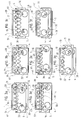
- the training device opening or closing of a sliding leaf door, gate, window, shutter or the like comprises a frame 1 having a groove 10 constituting a slide for a slide 2 which may consist of an opening to move or in part of an opening to move.
- the slider 2 may be integral with the frame, while the frame 1 may be integral with the door and move with it.
- the frame 1 further comprises two shafts 11, perpendicular to the sliding plane of the slider 2, aligned parallel to the groove 10 and capable of being simultaneously rotated in the same direction , and on each of which is intended to be wedged a crankshaft 3.
- crankshafts 3 are identical, they each consist of three eccentric discs 30, 31 and 32, of the same dimensions, secured to one another, and offset angularly by 120 °.
- the drive device also comprises three identical combs 4, 5 and 6, each of which is in the form of a rectangular plate comprising on the one hand an edge, respectively 40, 50 and 60, a succession regular notches, respectively 41, 51 and 61; and secondly two round lights, respectively 42, 52 and 62, of similar dimensions to those of the eccentric discs 30, 31 and 32, aligned parallel to the notched edge 40, 50 and 60, and of spacing corresponding to that of the shafts. 11.
- the dimensions of the eccentric discs 30, 31 and 32 and round lights 41, 51 and 61 are determined so as to allow the former to rotate in seconds, and it can be provided by construction, to favor the Relative movements, lubrication and / or inserting bearings.
- the drive device consists of the assembly of the combs 4, 5 and 6, on the crankshafts 3 themselves wedged on the shafts 11 in an identical manner.
- the assembly is carried out in the following manner, the discs 30 are housed in the slots 42 of the comb 4, the discs 31 are housed in the slots 52 of the comb 5, and the discs 32 are housed in the slots 62 of the comb 6.
- crankshafts 3 causes each of the combs 4, 5 and 6 in a circular translational movement, the movement of each of the combs being, because of the angular displacement of the discs 30, 31 and 32, out of phase with the movement of each of the other two.
- each of the disks being able for example to be replaced by a radial arm to the shaft 11, and carrying at the end a swiveling pivot in a comb, with however the disadvantage of less compactness.
- the dimensions of the combs 4, 5 and 6, and those of the frame 1 and the implantation of the shafts 11, are chosen so that in the circular translation movement of the combs 4, 5 and 6, the notched edge 40, 50 and 60 , from these momentarily come to stand above the throat 10.
- the slider 2 is further provided with a finger 20 which extends perpendicular to the sliding plane of the slider 2, which passes through the planes of the three combs 4, 5 and 6, and which has transverse dimensions complementary to those of the notches 41, 51 and 61, so as to be able to mesh with it, preferably closely.
- FIGS. 3a, 3b, 3c, 3d, 3e, 3f and 3g it is possible to see successive phases for driving the slide 2 in translation in the slideway 10.
- the slider 2 is at one end of the slider 10, and the finger 20 is meshed on a notch 51 of the comb 5, in this case the second notch 51 from the end of the comb 5 on the side of the initial position of the slider 2.
- each of the notches 51 of the comb 5 describes an arc of circle, and that with which the finger 20 is engaged, causes this last and so the slider 2.
- the extension of the rotation R also of a value of 45 °, causes the beginning of the disengagement of the finger 20 and the comb 5, and of its meshing with the comb 4. It will be noted that the finger 20 is disengaging the second notch 51 of the comb 5, while it engages in the third notch 41 of the comb 4.
- the comb 6 begins to disengage from the finger 20, whereas the comb 5 begins to mesh with the finger 20 by its fifth notch 51.
- the continuous rotation R of the crankshafts 3 thus makes it possible to move the slider 2 step by step, successively using the combs 4, 5 and 6.
- the slider 2 can thus describe the entire length of the slider 10, in one direction or the other, depending on the direction of rotation of the crankshafts 3.
- the opening to move in this case the slider 2 is guided in rectilinear sliding which ensures its meshing with the combs 4, 5 and 6 but it is possible to envisage that the opening to move is not guided, and also that it does not move only rectilinear way.
- the opening to be moved to engage by gravity in the combs 4, 5 and 6 which then extend in vertical planes, notched edges directed upwards.
- the drive device according to the invention has many advantages over existing devices, using for example a rack device cooperating with a pinion.
- the depth of engagement of the teeth of the pinion in those of the rack, and thus the rigidity of the connection depends on the length of said teeth, and therefore strongly depends on the diameter of said pinion, which acts directly on the gear ratio.
- the depth of the notches 41, 51 and 61 is limited only by the eccentric distance eccentric 30, 31 and 32.
- the drive device according to the invention allows a very rigid connection while being compact.
- the locking of the device can be ensured, regardless of the position of the opening, through a movable part adapted to come to immobilize one of the combs 4, 5 and 6, for example by taking support on the edge opposite the notched edge 40, 50 or 60.
Landscapes
- Engineering & Computer Science (AREA)
- General Engineering & Computer Science (AREA)
- Mechanical Engineering (AREA)
- Power-Operated Mechanisms For Wings (AREA)
- Transmission Devices (AREA)
Applications Claiming Priority (1)
| Application Number | Priority Date | Filing Date | Title |
|---|---|---|---|
| FR0652021A FR2901856B1 (fr) | 2006-06-06 | 2006-06-06 | Dispositif d'entrainement en translation d'un objet |
Publications (3)
| Publication Number | Publication Date |
|---|---|
| EP1865140A2 true EP1865140A2 (de) | 2007-12-12 |
| EP1865140A3 EP1865140A3 (de) | 2012-12-19 |
| EP1865140B1 EP1865140B1 (de) | 2014-05-07 |
Family
ID=37873255
Family Applications (1)
| Application Number | Title | Priority Date | Filing Date |
|---|---|---|---|
| EP07301087.8A Active EP1865140B1 (de) | 2006-06-06 | 2007-06-06 | Antriebsvorrichtung zum Öffnen oder Schließen eines Schiebeelements und Schiebeelement, das mit einer solchen Antriebsvorrichtung ausgestattet ist |
Country Status (3)
| Country | Link |
|---|---|
| EP (1) | EP1865140B1 (de) |
| ES (1) | ES2487501T3 (de) |
| FR (1) | FR2901856B1 (de) |
Family Cites Families (4)
| Publication number | Priority date | Publication date | Assignee | Title |
|---|---|---|---|---|
| JPH07280057A (ja) * | 1994-04-06 | 1995-10-27 | Teijin Seiki Co Ltd | 直進運動機構およびその作製方法並びにその作製方法を実施する加工機械 |
| JPH09105446A (ja) * | 1995-10-12 | 1997-04-22 | Teijin Seiki Co Ltd | 直進運動装置 |
| JPH09119496A (ja) * | 1995-10-24 | 1997-05-06 | Teijin Seiki Co Ltd | 直進運動装置 |
| FR2834530B1 (fr) * | 2002-01-04 | 2005-01-28 | Anne Bertolus | Dispositif pour la motorisation d'une fenetre ou d'une baie coulissante |
-
2006
- 2006-06-06 FR FR0652021A patent/FR2901856B1/fr not_active Expired - Fee Related
-
2007
- 2007-06-06 EP EP07301087.8A patent/EP1865140B1/de active Active
- 2007-06-06 ES ES07301087.8T patent/ES2487501T3/es active Active
Non-Patent Citations (1)
| Title |
|---|
| None |
Also Published As
| Publication number | Publication date |
|---|---|
| EP1865140A3 (de) | 2012-12-19 |
| FR2901856A1 (fr) | 2007-12-07 |
| ES2487501T3 (es) | 2014-08-21 |
| EP1865140B1 (de) | 2014-05-07 |
| FR2901856B1 (fr) | 2009-02-06 |
Similar Documents
| Publication | Publication Date | Title |
|---|---|---|
| EP2097603B1 (de) | Elektromechanischer antrieb zum betätigen eines flügels und schliessvorrichtung mit einem solchen antrieb | |
| CA3042195C (fr) | Dispositif de verrouillage a verrou rotatif a commande impulsionnelle | |
| EP1760336B1 (de) | Pleuel mit im Betrieb variabler Länge | |
| EP1865140B1 (de) | Antriebsvorrichtung zum Öffnen oder Schließen eines Schiebeelements und Schiebeelement, das mit einer solchen Antriebsvorrichtung ausgestattet ist | |
| EP0709535A2 (de) | Ausschaltbare Kupplungsvorrichtung für zwei, mit Betätigungshändel eines Schlosses verbundenen, koaxialen Achsen | |
| CH636165A5 (fr) | Dispositif de commande pour moto-reducteur electrique. | |
| EP1441155B1 (de) | Steuervorrichtung für ein Schaltgetriebe zum schnelleren Schalten, mit dem zugehörigen Schaltverfahren | |
| EP3376308B1 (de) | Aufziehmechanismus einer uhr | |
| CH707741B1 (fr) | Mécanisme de remontage automatique. | |
| FR2822517A1 (fr) | Dispositif de commande de changement de rapport de transmission dans une boite de vitesses | |
| FR3125497A1 (fr) | Volant de véhicule comprenant des mécanismes et un actionneur de commande. | |
| EP0976902A1 (de) | Elektrisches Schlossmodul für den Kofferraumdeckel eines Kraftfahrzeuges | |
| FR2747169A1 (fr) | Boitier de transformation de mouvement, rotatif-alternatif, ou inversement avec changement possible de direction, de frequence, de phase et d'amplitude | |
| EP0434614B1 (de) | Automatische Arretierungsvorrichtung für einen elektrischen Motor nach einer bestimmten Anzahl von Umdrehungen | |
| EP0584002B1 (de) | Verriegelungsvorrichtung für das Verschlussmittel einer Öffnung, z.B. eine Tür | |
| EP0931953A1 (de) | Drehmomenttragende Vorrichtung mit trägkeitsbetätigter Kupplung | |
| CH713582A2 (fr) | Mécanisme de remontage d'une pièce d'horlogerie. | |
| FR2525724A1 (fr) | Mecanisme d'activation d'une vanne | |
| EP1640555B1 (de) | Drive with automatic clutch for a building closure | |
| FR3087474A1 (fr) | Procede de controle d'un systeme d'actionnement d'un premier et d'un second ecrans et systeme d'actionnement | |
| EP1549818B1 (de) | Vorrichtung zum steuern eines motorisierten rolladens | |
| FR2926033A1 (fr) | Outillage rotatif un systeme d'entrainement a encliquetage, comprenant un organe de selection du sens de rotation mobile en translation. | |
| FR2811051A1 (fr) | Dispositif de commande pour relier un pignon monte fou sur un arbre et cet arbre, notamment pour boite de vitesses de vehicule automobile | |
| FR3059752A1 (fr) | Moyen d'agrippement autobloquant d'un systeme de transmission continument variable | |
| EP4249710A1 (de) | Steuervorrichtung für ein treibstangenschloss für einen schiebeflügel |
Legal Events
| Date | Code | Title | Description |
|---|---|---|---|
| PUAI | Public reference made under article 153(3) epc to a published international application that has entered the european phase |
Free format text: ORIGINAL CODE: 0009012 |
|
| AK | Designated contracting states |
Kind code of ref document: A2 Designated state(s): AT BE BG CH CY CZ DE DK EE ES FI FR GB GR HU IE IS IT LI LT LU LV MC MT NL PL PT RO SE SI SK TR |
|
| AX | Request for extension of the european patent |
Extension state: AL BA HR MK YU |
|
| PUAL | Search report despatched |
Free format text: ORIGINAL CODE: 0009013 |
|
| AK | Designated contracting states |
Kind code of ref document: A3 Designated state(s): AT BE BG CH CY CZ DE DK EE ES FI FR GB GR HU IE IS IT LI LT LU LV MC MT NL PL PT RO SE SI SK TR |
|
| AX | Request for extension of the european patent |
Extension state: AL BA HR MK RS |
|
| RIC1 | Information provided on ipc code assigned before grant |
Ipc: F16H 21/18 20060101ALN20121114BHEP Ipc: E05F 15/14 20060101AFI20121114BHEP Ipc: F16H 25/08 20060101ALI20121114BHEP |
|
| 17P | Request for examination filed |
Effective date: 20130219 |
|
| AKX | Designation fees paid |
Designated state(s): DE ES FR IT |
|
| RIC1 | Information provided on ipc code assigned before grant |
Ipc: E05F 15/14 20060101AFI20130819BHEP Ipc: F16H 25/02 20060101ALI20130819BHEP Ipc: F16H 25/08 20060101ALI20130819BHEP Ipc: F16H 21/18 20060101ALN20130819BHEP |
|
| RIC1 | Information provided on ipc code assigned before grant |
Ipc: F16H 25/02 20060101ALI20130913BHEP Ipc: E05F 15/14 20060101AFI20130913BHEP Ipc: F16H 21/18 20060101ALN20130913BHEP Ipc: F16H 25/08 20060101ALI20130913BHEP |
|
| RIC1 | Information provided on ipc code assigned before grant |
Ipc: F16H 25/02 20060101ALI20131127BHEP Ipc: F16H 25/08 20060101ALI20131127BHEP Ipc: F16H 21/18 20060101ALN20131127BHEP Ipc: E05F 15/14 20060101AFI20131127BHEP |
|
| RIC1 | Information provided on ipc code assigned before grant |
Ipc: E05F 15/14 20060101AFI20131219BHEP Ipc: F16H 25/02 20060101ALI20131219BHEP Ipc: F16H 21/18 20060101ALN20131219BHEP Ipc: F16H 25/08 20060101ALI20131219BHEP |
|
| GRAP | Despatch of communication of intention to grant a patent |
Free format text: ORIGINAL CODE: EPIDOSNIGR1 |
|
| INTG | Intention to grant announced |
Effective date: 20140129 |
|
| RIC1 | Information provided on ipc code assigned before grant |
Ipc: F16H 21/18 20060101ALN20140121BHEP Ipc: E05F 15/14 20060101AFI20140121BHEP Ipc: F16H 25/08 20060101ALI20140121BHEP Ipc: F16H 25/02 20060101ALI20140121BHEP |
|
| GRAS | Grant fee paid |
Free format text: ORIGINAL CODE: EPIDOSNIGR3 |
|
| GRAA | (expected) grant |
Free format text: ORIGINAL CODE: 0009210 |
|
| AK | Designated contracting states |
Kind code of ref document: B1 Designated state(s): DE ES FR IT |
|
| REG | Reference to a national code |
Ref country code: DE Ref legal event code: R096 Ref document number: 602007036479 Country of ref document: DE Effective date: 20140626 |
|
| REG | Reference to a national code |
Ref country code: ES Ref legal event code: FG2A Ref document number: 2487501 Country of ref document: ES Kind code of ref document: T3 Effective date: 20140821 |
|
| REG | Reference to a national code |
Ref country code: DE Ref legal event code: R097 Ref document number: 602007036479 Country of ref document: DE |
|
| PLBE | No opposition filed within time limit |
Free format text: ORIGINAL CODE: 0009261 |
|
| STAA | Information on the status of an ep patent application or granted ep patent |
Free format text: STATUS: NO OPPOSITION FILED WITHIN TIME LIMIT |
|
| 26N | No opposition filed |
Effective date: 20150210 |
|
| REG | Reference to a national code |
Ref country code: DE Ref legal event code: R097 Ref document number: 602007036479 Country of ref document: DE Effective date: 20150210 |
|
| REG | Reference to a national code |
Ref country code: DE Ref legal event code: R082 Ref document number: 602007036479 Country of ref document: DE Representative=s name: PATENTANWAELTE UND RECHTSANWALT DR. WEISS, ARA, DE Ref country code: DE Ref legal event code: R082 Ref document number: 602007036479 Country of ref document: DE Representative=s name: PATENTANWAELTE UND RECHTSANWALT WEISS, ARAT & , DE |
|
| REG | Reference to a national code |
Ref country code: FR Ref legal event code: PLFP Year of fee payment: 10 |
|
| REG | Reference to a national code |
Ref country code: FR Ref legal event code: PLFP Year of fee payment: 11 |
|
| REG | Reference to a national code |
Ref country code: FR Ref legal event code: PLFP Year of fee payment: 12 |
|
| PGFP | Annual fee paid to national office [announced via postgrant information from national office to epo] |
Ref country code: FR Payment date: 20250317 Year of fee payment: 19 |
|
| PGFP | Annual fee paid to national office [announced via postgrant information from national office to epo] |
Ref country code: DE Payment date: 20250617 Year of fee payment: 19 |
|
| PGFP | Annual fee paid to national office [announced via postgrant information from national office to epo] |
Ref country code: ES Payment date: 20250710 Year of fee payment: 19 |
|
| PGFP | Annual fee paid to national office [announced via postgrant information from national office to epo] |
Ref country code: IT Payment date: 20250606 Year of fee payment: 19 |