EP1864757A1 - Use of magnets to provide resilience - Google Patents
Use of magnets to provide resilience Download PDFInfo
- Publication number
- EP1864757A1 EP1864757A1 EP06011816A EP06011816A EP1864757A1 EP 1864757 A1 EP1864757 A1 EP 1864757A1 EP 06011816 A EP06011816 A EP 06011816A EP 06011816 A EP06011816 A EP 06011816A EP 1864757 A1 EP1864757 A1 EP 1864757A1
- Authority
- EP
- European Patent Office
- Prior art keywords
- magnet
- lever
- magnets
- jaw
- levers
- Prior art date
- Legal status (The legal status is an assumption and is not a legal conclusion. Google has not performed a legal analysis and makes no representation as to the accuracy of the status listed.)
- Granted
Links
Images
Classifications
-
- B—PERFORMING OPERATIONS; TRANSPORTING
- B25—HAND TOOLS; PORTABLE POWER-DRIVEN TOOLS; MANIPULATORS
- B25B—TOOLS OR BENCH DEVICES NOT OTHERWISE PROVIDED FOR, FOR FASTENING, CONNECTING, DISENGAGING, OR HOLDING
- B25B5/00—Clamps
- B25B5/06—Arrangements for positively actuating jaws
-
- B—PERFORMING OPERATIONS; TRANSPORTING
- B25—HAND TOOLS; PORTABLE POWER-DRIVEN TOOLS; MANIPULATORS
- B25B—TOOLS OR BENCH DEVICES NOT OTHERWISE PROVIDED FOR, FOR FASTENING, CONNECTING, DISENGAGING, OR HOLDING
- B25B11/00—Work holders not covered by any preceding group in the subclass, e.g. magnetic work holders, vacuum work holders
- B25B11/002—Magnetic work holders
-
- G—PHYSICS
- G01—MEASURING; TESTING
- G01R—MEASURING ELECTRIC VARIABLES; MEASURING MAGNETIC VARIABLES
- G01R1/00—Details of instruments or arrangements of the types included in groups G01R5/00 - G01R13/00 and G01R31/00
- G01R1/02—General constructional details
- G01R1/06—Measuring leads; Measuring probes
- G01R1/067—Measuring probes
- G01R1/06788—Hand-held or hand-manipulated probes, e.g. for oscilloscopes or for portable test instruments
Definitions
- This disclosure relates to clamping devices, optionally of an operated-by-hand character, in which a person's hand operates against a resilience to open the jaws of the clamp, and the resilience serves to hold the jaws together when the clamp is released.
- the new design is optionally for use in the field of clamping such items as circuit-boards for finished-production testing.
- the clamping apparatus is used for clamping a circuit board 20 during testing.
- a clamp-unit 23 includes electrical components 24, which interact with the circuit board 20 being tested.
- the unit 23 also includes wiring 25 for connecting the electrical components 24 to a base station (not shown) containing the testing instruments etc.
- the clamp unit 23 includes an upper-jaw 26 and a lower-jaw 27.
- the jaws 26,27 are components of respective levers, being an upper-lever 30 and a lower-lever 31.
- the levers 30,31 include respective pivot-bosses 32,33, which are linked by a pivot-pin 29.
- the clamp-unit 23 includes an upper-magnet 34 and a lower-magnet 35.
- the magnets 34,35 are carried at the respective magnet-ends 36,37 of the two levers 30,31.
- the magnets 34,35 are arranged with the respective same-poles of the magnets facing each other, in opposition, whereby the magnets repel each other.
- the magnets 34,35 are carried in respective magnet-sockets 38,39 formed in the magnet-ends 36,37 of the levers 30,31.
- the magnets themselves are in the form of circular discs, and the magnet-sockets 38,39 are complementarily circular, and sized such that the magnets fit snugly but still loosely within the sockets.
- the sockets locate the magnets, and prevent the magnets from slipping laterally (sideways) with respect to the levers 30,31.
- the magnets may be fixed, e.g glued, into the sockets. However, once in place in the sockets, the magnets are prevented from falling out of the sockets by the magnetic forces, whereby further fixing means might not be needed.
- the material of the levers 30,31 is non-magnetic. In the example, the material is hard plastic.
- Class-1 double-levers can be arranged in a cross-pivot or scissors configuration; alternatively, class-1 double-levers can be arranged in a rocker-pivot or clothes-pin configuration.
- the lever arrangement as shown in Figs 1,2 is a class-1 double-lever clothes-pin arrangement.
- the clamp unit 23, as shown, was intended to be operated manually by a person, especially by an inspector performing the task of inspecting circuit-boards.
- the forces exerted by the magnets, and the geometry of the clamp unit (including the lever ratio) are such that the inspector can press the magnet-ends 36,37 of the levers 30,31 together, by the use of one hand, and can thereby open the jaws 26,27.
- the other hand then is available to remove the just-tested circuit-board and insert a fresh one between the jaws. With a fresh circuit-board in place, the inspector releases the clamp, and the jaws close onto the circuit board with the predetermined force as exerted by the magnets. (Alternatively, of course, the designer might choose to automate the task of opening and closing the jaws.)
- the lower magnet-socket 39 is so formed as to leave a thin wall 40 of thickness T, covering the lower pole of the disc of the lower-magnet 35.
- the clamp unit 23 is placed on a tabletop 42, which, in the example shown, is a sheet of steel. It is often the case that the inspector wishes to be able to slide the clamp-unit 23 (with or without the under-test circuit-board 20 clamped between the jaws 26,27 thereof) around, on the tabletop 42, and yet the clamp-unit remains firmly held to the tabletop. That is to say, it is desired that the clamp unit can be moved around the tabletop upon the inspector touching or grasping the unit and exerting hand forces on the unit, in order to move the unit; and it is desired that, in the absence of such touching or grasping, the magnetic attraction is sufficient to hold the clamp unit stationary and firmly with respect to the tabletop.
- the magnet resists separation of the clamp unit from the steel tabletop.
- the magnet itself is kept from touching directly against the tabletop by reason of the separation due to the thickness T of the plastic material 40.
- the designer might make the thickness T greater, whereby the magnetic force holding the clamp unit to the table is reducedor might make the thickness T smaller, which increases the magnetic force.
- the designer should arrange for the thickness T of the thin wall 40 to be small enough that the lower pole of the lower-magnet 35 is close enough to the steel to exert a substantial magnetic attraction. The clamp-unit 23 is then held firmly against the tabletop 42 by this magnetic attraction.
- the inspector be able to move the clamp-unit around on the tabletop.
- the resistance to such lateral movement is the friction that acts parallel to the tabletop, which is proportional to the magnitude of the magnetic attraction, and the designer should arrange for the thickness T to be thick enough that this friction can be easily overcome by the forces exerted by the inspector's hand.
- a lateral frictional resistive force is required of say ten Newtons, the coefficient of friction of plastic against (dry) steel being approximately 0.15, an attractive magnetic force of about sixty Newtons would be required, and the thickness T should be set accordingly.
- the clamp-unit 23 requires a minimum of one pair of magnets.
- the two magnets that make up the pair are arranged to repel each other.
- the designer will usually find it convenient to provide two pairs of magnets.
- four pairs may be provided. If the magnets are not glued in, it is possible for the magnets to be slipped into and out of their sockets by hand, whereby, at least in the Fig 3 apparatus, the inspector can easily increase or decrease the overall magnetic forces.
- the designer can also adjust the clamping force by setting the lever ratio of the clamping unit appropriately.
- the magnets should be of such material and of such size as will provide the desired level of force.
- the (disc) magnets were twelve mm diameter and five mm thick.
- the magnets were rare-earth magnets, specifically of nickel-plated neodymium-iron-boron. Each opposed pair of magnets exerted a repel force, over a relative travel vector of six mm, of fifty Newtons.
- the jaws and the magnets were roughly equidistant from the pivot axis.
- the thickness T of the thin wall was 1.5 mm.
- the magnets are permanent magnets, and this is preferred for simplicity, convenience and long-term reliability.
- electro-magnets are not ruled out. Electro-magnets might be useful, for example, in that they permit simple automation. In some cases, the magnets (permanent, or electro-) may be supplemented by coilsprings, or other types of resilient springs.
- the magnets In an apparatus that uses magnets in repulsion, the magnets have a tendency to sideslip. Compared with compression coilsprings, designers usually have more options when it comes to arranging for the two ends of a coilspring to remain in alignment throughout the stroke of the coilspring, than to arrange for two magnets, in repulsion, to remain in alignment throughout their stroke.
- the magnets have no inherent resistance at all to sideslip, whereas a coilspring does have its own structure.
- the structure of the device as a whole lends itself to keeping the magnets in proper alignment.
- the levers are of robust rigid construction, as is the pivot structure, and together these ensure that the levers remain aligned with each other, and constrained against all modes of movements and deflections other than the defined pivoting movement.
- the magnets are safe against tipping, rocking, sideslipping, and all the other possible modes of movement.
- the magnets can move only in the one mode of movement, i.e towards and away from each other along the path as defined and controlled and guided, by the pivot structure.
- the magnets cannot move relatively in any other mode.
- the force desired to be exerted on the circuit-board, to secure the circuit-board firmly between the jaws often is of more or less the same order as the force that can be readily obtained from two pairs of simple disc magnets, of such size as described, arranged in repulsive pairs.
- the desired magnitude of forces at the jaws is most easily provided when the lever ratio between the applied force (from the magnets) and the load (between the jaws) is roughly one-to-one.
- a one-to-one ratio is not impossible in the class-2 and class-3 arrangements, practically the class-1 arrangement, as described, is most convenient.
- the wiring 25 by which the unit 23 is connected electrically to the base station usually is required, as shown, to be arranged in flexible pig-tail fashion. It would be all too easy, when the biassing force of the clamp is provided by a coilspring, for the wires to become snagged or tangled up in the coils, with the resulting possibility of damage to the wiring when the clamp is operated. None like that happens when the force is provided by magnets in repulsion.
- disc magnets in the size and shape as described, are simple to use and effective in performance. It is preferred to use a plurality of opposed pairs, to achieve a given force magnitude, rather than just one pair of large magnets. With a magnet in the form of a large disc, it can be difficult to ensure that the effective centre of the magnetic pole is in the geometric centre of the disc, and, with a large disc, it does not take much, by way of mis-match or offset of the opposing or facing same-poles, for the magnitude of the repel force to be compromised. In an extreme, two opposed large-diameter disc magnets might enter a state in which they might even repel each other over one sector but attract each other over another sector, which would be detrimental in the present case. With smaller-diameter magnets, the manner in which the magnet forces are exerted is much less likely to enter such spurious areas.
- a magnet that has a diameter-to-length ratio of more than about 1:1 might start to exhibit some instability, in the above regard. Above 2:1, the likelihood of instability and/or effective loss of force is so great that magnets with such ratios preferably should not be employed.
- the pressing unit may include a magnetic spring comprising a pair of magnets arranged so that the same poles of the magnets are opposite to each other.”
- the function of the clamp-unit as described herein is to provide a clamping force, of the type and under the conditions as described.
- the action of a clamp may be contrasted with, for example, the action of a cushion.
- the spring is not used to bias a pair of jaws together, where the resilience of the biassing spring has to be overcome to force the jaws apart. Rather, in Haseyama, the magnetic spring is used as a force-limiting cushion.
- the preferred lever configuration is the class-1 double-lever clothes-pin configuration, in which the magnets are set to repel each other. It might be considered that the class-1 double-lever cross-pivot or scissors arrangement would be equivalent, if the magnets now were set to attract each other. However, that arrangement is not preferred, in that it is considerably more difficult to open a pair of jaws, against a resilient force, by pulling levers apart, than to open the jaws by pushing levers together. In the clothes-pin configuration, the clamp force at the jaws is set by the spring, and is predictable. At the same time, the inspector's hand force is readily available, and easily applied, to open the jaws.
Landscapes
- Engineering & Computer Science (AREA)
- Mechanical Engineering (AREA)
- Physics & Mathematics (AREA)
- General Physics & Mathematics (AREA)
- Clamps And Clips (AREA)
- Magnetic Treatment Devices (AREA)
- Press Drives And Press Lines (AREA)
- Manipulator (AREA)
- Jigs For Machine Tools (AREA)
- Details Of Connecting Devices For Male And Female Coupling (AREA)
- Sheet Holders (AREA)
- Low-Molecular Organic Synthesis Reactions Using Catalysts (AREA)
- Magnetic Resonance Imaging Apparatus (AREA)
Abstract
Description
- This disclosure relates to clamping devices, optionally of an operated-by-hand character, in which a person's hand operates against a resilience to open the jaws of the clamp, and the resilience serves to hold the jaws together when the clamp is released. The new design is optionally for use in the field of clamping such items as circuit-boards for finished-production testing.
- Exemplary apparatuses will now be described with reference to the accompanying drawings, in which:
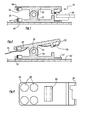
- Fig 1 is a sectioned side elevation of a clamping apparatus, which uses permanent magnets as the source of the clamping force.
- Fig 2 is the same view as Fig 1 but shows the clamping apparatus in an opened configuration.
- Fig 3 is a plan view of a modified version of one of the levers of the clamping apparatus of Fig 1.
- The apparatuses shown in the accompanying drawings and described below are examples. The scope of patent protection sought is defined by the accompanying claims, and not necessarily by specific features of the exemplary apparatuses.
- The clamping apparatus is used for clamping a
circuit board 20 during testing. A clamp-unit 23 includeselectrical components 24, which interact with thecircuit board 20 being tested. Theunit 23 also includeswiring 25 for connecting theelectrical components 24 to a base station (not shown) containing the testing instruments etc. - The
clamp unit 23 includes an upper-jaw 26 and a lower-jaw 27. Thejaws lever 30 and a lower-lever 31. - The
levers bosses pin 29. - The clamp-
unit 23 includes an upper-magnet 34 and a lower-magnet 35. Themagnets ends magnets - The
magnets sockets ends levers sockets levers - The magnets may be fixed, e.g glued, into the sockets. However, once in place in the sockets, the magnets are prevented from falling out of the sockets by the magnetic forces, whereby further fixing means might not be needed.
- The material of the
levers - The following text-book convention is used to describe the various classes of arrangement of levers and the forces thereon. In a class-1 lever, the pivot lies between the applied-force and the load. In a class-2 and a class-3 lever, the arrangement is that the pivot is at one end of the lever, and both the applied-force and the load lie to the same side of the pivot. In class-2, the load lies between the applied-force and the pivot, and in class-3 the applied-force lies between the load and the pivot.
- Class-1 double-levers can be arranged in a cross-pivot or scissors configuration; alternatively, class-1 double-levers can be arranged in a rocker-pivot or clothes-pin configuration. The lever arrangement as shown in Figs 1,2 is a class-1 double-lever clothes-pin arrangement.
- The
clamp unit 23, as shown, was intended to be operated manually by a person, especially by an inspector performing the task of inspecting circuit-boards. The forces exerted by the magnets, and the geometry of the clamp unit (including the lever ratio) are such that the inspector can press the magnet-ends levers jaws - The lower magnet-
socket 39 is so formed as to leave athin wall 40 of thickness T, covering the lower pole of the disc of the lower-magnet 35. - The
clamp unit 23 is placed on atabletop 42, which, in the example shown, is a sheet of steel. It is often the case that the inspector wishes to be able to slide the clamp-unit 23 (with or without the under-test circuit-board 20 clamped between thejaws tabletop 42, and yet the clamp-unit remains firmly held to the tabletop. That is to say, it is desired that the clamp unit can be moved around the tabletop upon the inspector touching or grasping the unit and exerting hand forces on the unit, in order to move the unit; and it is desired that, in the absence of such touching or grasping, the magnetic attraction is sufficient to hold the clamp unit stationary and firmly with respect to the tabletop. - This condition is achieved in the apparatus as shown. The magnet resists separation of the clamp unit from the steel tabletop. The magnet itself, however, is kept from touching directly against the tabletop by reason of the separation due to the thickness T of the
plastic material 40. - The designer might make the thickness T greater, whereby the magnetic force holding the clamp unit to the table is reducedor might make the thickness T smaller, which increases the magnetic force. In order to permit the device to remain stationary and stable on the tabletop when the inspector is not moving the device around, the designer should arrange for the thickness T of the
thin wall 40 to be small enough that the lower pole of the lower-magnet 35 is close enough to the steel to exert a substantial magnetic attraction. The clamp-unit 23 is then held firmly against thetabletop 42 by this magnetic attraction. - On the other hand, it is desired that the inspector be able to move the clamp-unit around on the tabletop. The resistance to such lateral movement is the friction that acts parallel to the tabletop, which is proportional to the magnitude of the magnetic attraction, and the designer should arrange for the thickness T to be thick enough that this friction can be easily overcome by the forces exerted by the inspector's hand. Thus, if a lateral frictional resistive force is required of say ten Newtons, the coefficient of friction of plastic against (dry) steel being approximately 0.15, an attractive magnetic force of about sixty Newtons would be required, and the thickness T should be set accordingly.
- The clamp-
unit 23 requires a minimum of one pair of magnets. Preferably, the two magnets that make up the pair are arranged to repel each other. As shown in Figs 1,2 the designer will usually find it convenient to provide two pairs of magnets. As shown in Fig 3, four pairs may be provided. If the magnets are not glued in, it is possible for the magnets to be slipped into and out of their sockets by hand, whereby, at least in the Fig 3 apparatus, the inspector can easily increase or decrease the overall magnetic forces. The designer can also adjust the clamping force by setting the lever ratio of the clamping unit appropriately. - The magnets should be of such material and of such size as will provide the desired level of force. In the illustrated apparatus, the (disc) magnets were twelve mm diameter and five mm thick. The magnets were rare-earth magnets, specifically of nickel-plated neodymium-iron-boron. Each opposed pair of magnets exerted a repel force, over a relative travel vector of six mm, of fifty Newtons. The jaws and the magnets were roughly equidistant from the pivot axis. The thickness T of the thin wall was 1.5 mm.
- As shown, the magnets are permanent magnets, and this is preferred for simplicity, convenience and long-term reliability. However, electro-magnets are not ruled out. Electro-magnets might be useful, for example, in that they permit simple automation. In some cases, the magnets (permanent, or electro-) may be supplemented by coilsprings, or other types of resilient springs.
- In an apparatus that uses magnets in repulsion, the magnets have a tendency to sideslip. Compared with compression coilsprings, designers usually have more options when it comes to arranging for the two ends of a coilspring to remain in alignment throughout the stroke of the coilspring, than to arrange for two magnets, in repulsion, to remain in alignment throughout their stroke. The magnets have no inherent resistance at all to sideslip, whereas a coilspring does have its own structure.
- In the illustrated device, the structure of the device as a whole lends itself to keeping the magnets in proper alignment. Mounting the magnets in robust levers, with robust pivots, that are safe against any mode of movement other than the defined pivoting movement, counters any tendency the magnets might have to sideslip, relative to each other and to the levers. The levers are of robust rigid construction, as is the pivot structure, and together these ensure that the levers remain aligned with each other, and constrained against all modes of movements and deflections other than the defined pivoting movement.
- Held thus, the magnets are safe against tipping, rocking, sideslipping, and all the other possible modes of movement. The magnets can move only in the one mode of movement, i.e towards and away from each other along the path as defined and controlled and guided, by the pivot structure. The magnets cannot move relatively in any other mode.
- It is noted that the force desired to be exerted on the circuit-board, to secure the circuit-board firmly between the jaws, often is of more or less the same order as the force that can be readily obtained from two pairs of simple disc magnets, of such size as described, arranged in repulsive pairs. Thus, the desired magnitude of forces at the jaws is most easily provided when the lever ratio between the applied force (from the magnets) and the load (between the jaws) is roughly one-to-one. Although a one-to-one ratio is not impossible in the class-2 and class-3 arrangements, practically the class-1 arrangement, as described, is most convenient.
- It is generally not desirable to locate strong magnets close to a circuit-board. It is all too easy for electronic components to be affected, if not actually damaged, by being in close proximity to strong magnetic fields. Again, the class-1 lever arrangement ensures that the (strong) magnets are safely spaced away from the possibly-sensitive components -- being the
components 24 as well as the components of the circuit-board 20. - The
wiring 25 by which theunit 23 is connected electrically to the base station usually is required, as shown, to be arranged in flexible pig-tail fashion. It would be all too easy, when the biassing force of the clamp is provided by a coilspring, for the wires to become snagged or tangled up in the coils, with the resulting possibility of damage to the wiring when the clamp is operated. Nothing like that happens when the force is provided by magnets in repulsion. - It is recognised that disc magnets, in the size and shape as described, are simple to use and effective in performance. It is preferred to use a plurality of opposed pairs, to achieve a given force magnitude, rather than just one pair of large magnets. With a magnet in the form of a large disc, it can be difficult to ensure that the effective centre of the magnetic pole is in the geometric centre of the disc, and, with a large disc, it does not take much, by way of mis-match or offset of the opposing or facing same-poles, for the magnitude of the repel force to be compromised. In an extreme, two opposed large-diameter disc magnets might enter a state in which they might even repel each other over one sector but attract each other over another sector, which would be detrimental in the present case. With smaller-diameter magnets, the manner in which the magnet forces are exerted is much less likely to enter such spurious areas.
- From this standpoint, a magnet that has a diameter-to-length ratio of more than about 1:1 might start to exhibit some instability, in the above regard. Above 2:1, the likelihood of instability and/or effective loss of force is so great that magnets with such ratios preferably should not be employed.
- The use of magnets for biassing components apart, or together, is well known. The use of magnets in clamping apparatuses, for holding electronic components in position while undergoing testing, is also known. In lines 25-26 of column 4 of
US-6,445,200 (Haseyama, 2002 ), referring to Fig 7D, which relates to such testing, appear the words: "the pressing unit may include a magnetic spring comprising a pair of magnets arranged so that the same poles of the magnets are opposite to each other." - It may be noted that the function of the clamp-unit as described herein is to provide a clamping force, of the type and under the conditions as described. The action of a clamp may be contrasted with, for example, the action of a cushion. In the Haseyama reference, even though the device is referred to as a "magnetic spring", the spring is not used to bias a pair of jaws together, where the resilience of the biassing spring has to be overcome to force the jaws apart. Rather, in Haseyama, the magnetic spring is used as a force-limiting cushion.
- As mentioned, the preferred lever configuration is the class-1 double-lever clothes-pin configuration, in which the magnets are set to repel each other. It might be considered that the class-1 double-lever cross-pivot or scissors arrangement would be equivalent, if the magnets now were set to attract each other. However, that arrangement is not preferred, in that it is considerably more difficult to open a pair of jaws, against a resilient force, by pulling levers apart, than to open the jaws by pushing levers together. In the clothes-pin configuration, the clamp force at the jaws is set by the spring, and is predictable. At the same time, the inspector's hand force is readily available, and easily applied, to open the jaws.
Claims (13)
- An operable clamping device, characterised by combining the following features:[2] the device includes two levers, being a lever-A and a lever-B;[3] lever-A carries a jaw-A at or near jaw-end-A of lever-A, and carries a pivot-boss-A;[4] lever-B carries a jaw-B at or near jaw-end-B of lever-B, and carries a pivot-boss-B;[5] a lever-pivot connects the pivot-boss-A to the pivot-boss-B, and defines a pivot-axis, about which jaw-A and jaw-B can undergo relative pivoting movement;[6] lever-A carries a magnet-A;[7] lever-B carries a magnet-B;[8] magnet-A and magnet-B are so mounted on the respective levers that poles of the magnets lie facing each other;[9] magnet-A and magnet-B are so mounted on the respective pivoting levers that magnet-A and magnet-B exert a magnetic force on each other, and thereby urge relative movement therebetween; and[10] the levers are so arranged that pivoting movement of magnet-A relative to magnet-B is accompanied by pivoting movement of their jaw-ends.
- As in claim 1, further characterised in that magnet-A and magnet-B are arranged with like-poles facing, whereby the magnets repel each other.
- As in claim 2, further characterised in that:[2] the clamp-unit is so structured that, as magnet-A and magnet-B move apart, so jaw-A and jaw-B move together;[3] whereby the repulsive magnetic force causes the jaws to be pressed together.
- As in claim 2, further characterised in that:[2] lever-A carries magnet-A at or near magnet-end-A of lever-A;[3] pivot-boss-A is located intermediate between jaw-end-A and magnet-end-A of lever-A;[4] lever-B carries magnet-B at or near magnet-end-B of lever-B;[5] pivot-boss-B is located intermediate between jaw-end-B and magnet-end-B of lever-B;
- As in claim 4, further characterised in that:[2] lever-A, lever-B, and the lever-pivot, are arranged in class-1, double-lever, clothes-pin configuration;[3] whereby pivoting movement apart of the magnet-ends of the levers is accompanied by pivoting movement together of the jaw-ends of the levers.
- As in claim 1, further characterised in that[2] lever-A, lever-B, and the lever-pivot, are arranged in class-1, double-lever, clothes-pin configuration;[3] whereby pivoting movement apart of the magnet-ends of the levers is accompanied by pivoting movement together of the jaw-ends of the levers;[4] magnet-A and magnet-B are arranged to repel each other, and thus to urge the magnet-ends apart, and thus to urge jaw-A and jaw-B together.
- As in claim 4, further characterised in that the jaw-end-A carries an electrical component, and carries an electrical lead that extends away from jaw-end-A towards magnet-end-A and beyond the magnet-end-A.
- As in claim 4, further characterised in that the structure of the apparatus is such that:[2] the jaws can be opened by squeezing together the magnet-ends of the levers, by hand; and[3] the jaws can be clamped together by releasing the magnet-ends.
- As in claim 4, further characterised in that:[2] magnet-A comprises two magnets, and magnet-B comprises two magnets; and[3] the two magnets of magnet-A and the two magnets of magnet-B are arranged in respective repulsive pairs.
- As in claim 9, further characterised in that the respective magnet-ends of the levers are provided with respective magnet-sockets, the magnet-sockets being so sized and shaped as to receive the magnets, and to locate the magnets against lateral movement relative to the levers.
- As in claim 10, further characterised in that each of the magnets is a permanent magnet.
- As in claim 9, further characterised in that each magnet is in the form of a cylinder, having flat ends, and the poles of the magnet are located in the flat ends.
- As in claim 4, further characterised in that the repulsive force between magnet-A and magnet-B is in the order of fifty Newtons.
Priority Applications (4)
| Application Number | Priority Date | Filing Date | Title |
|---|---|---|---|
| AT06011816T ATE494106T1 (en) | 2006-06-08 | 2006-06-08 | Clamping force generation through the use of magnets |
| DE602006019394T DE602006019394D1 (en) | 2006-06-08 | 2006-06-08 | Clamping force generation through the use of magnets |
| EP06011816A EP1864757B1 (en) | 2006-06-08 | 2006-06-08 | Use of magnets to provide resilience |
| CA2591343A CA2591343C (en) | 2006-06-08 | 2007-06-01 | Magnet-force clamping apparatus |
Applications Claiming Priority (1)
| Application Number | Priority Date | Filing Date | Title |
|---|---|---|---|
| EP06011816A EP1864757B1 (en) | 2006-06-08 | 2006-06-08 | Use of magnets to provide resilience |
Publications (2)
| Publication Number | Publication Date |
|---|---|
| EP1864757A1 true EP1864757A1 (en) | 2007-12-12 |
| EP1864757B1 EP1864757B1 (en) | 2011-01-05 |
Family
ID=37461467
Family Applications (1)
| Application Number | Title | Priority Date | Filing Date |
|---|---|---|---|
| EP06011816A Active EP1864757B1 (en) | 2006-06-08 | 2006-06-08 | Use of magnets to provide resilience |
Country Status (4)
| Country | Link |
|---|---|
| EP (1) | EP1864757B1 (en) |
| AT (1) | ATE494106T1 (en) |
| CA (1) | CA2591343C (en) |
| DE (1) | DE602006019394D1 (en) |
Cited By (5)
| Publication number | Priority date | Publication date | Assignee | Title |
|---|---|---|---|---|
| ITBG20080044A1 (en) * | 2008-09-05 | 2010-03-06 | Omaha S R L | CLAMP FOR LAUNDRY |
| WO2013096379A1 (en) * | 2011-12-22 | 2013-06-27 | Eaton Corporation | Magnetic latch |
| CN107449943A (en) * | 2017-07-27 | 2017-12-08 | 华中科技大学 | A kind of earth clamp for lightning arrester live-line test |
| CN112238402A (en) * | 2020-09-09 | 2021-01-19 | 大族激光科技产业集团股份有限公司 | Positioning device and detection system |
| CN117300214A (en) * | 2023-11-28 | 2023-12-29 | 成都弘林机械有限公司 | Panel processing drilling machine convenient to it is fixed |
Families Citing this family (1)
| Publication number | Priority date | Publication date | Assignee | Title |
|---|---|---|---|---|
| TWI706835B (en) * | 2019-09-20 | 2020-10-11 | 林立捷 | Clamp structure for fast changing tool head and assembling method thereof |
Citations (11)
| Publication number | Priority date | Publication date | Assignee | Title |
|---|---|---|---|---|
| GB611873A (en) * | 1946-05-11 | 1948-11-04 | Harold Jackson | Improvements relating to electro-magnetic clamps, vices and the like |
| DE912080C (en) | 1953-03-28 | 1954-05-24 | Guenter Geschke | Non-positive arrangement for opening or closing with pliers or scissors-like tools |
| US5445263A (en) * | 1994-09-14 | 1995-08-29 | Cajon Company | Gasket container and assembly tool |
| US5607344A (en) * | 1995-05-10 | 1997-03-04 | Endres; Nicholas | Apparatus for gripping and holding glass during a glass grinding process |
| US5828224A (en) * | 1994-03-18 | 1998-10-27 | Fujitsu, Limited | Test carrier for semiconductor integrated circuit and method of testing semiconductor integrated circuit |
| US6168221B1 (en) * | 1999-03-17 | 2001-01-02 | Daimlerchrysler Corporation | Magnetic carrier |
| US6279885B1 (en) * | 2000-09-08 | 2001-08-28 | Raymond Leon, Jr. | Magnetic clamp for welding magnetic objects |
| US20010040462A1 (en) * | 1998-02-19 | 2001-11-15 | Makoto Haseyama | Semiconductor element testing carrier using a membrane contactor and a semiconductor element testing method and apparatus using such a carrier |
| US20020038796A1 (en) * | 2000-10-03 | 2002-04-04 | Raymond Leon | Dual purpose welding clamp |
| DE20206846U1 (en) * | 2002-04-30 | 2003-09-11 | Wolfcraft GmbH, 56746 Kempenich | Suction cup device with spring clamp |
| FR2872077A1 (en) | 2004-06-24 | 2005-12-30 | Pass Technologies Sarl | HALF MAGNETIC HANDLE MULTI-USE FASTENING |
-
2006
- 2006-06-08 DE DE602006019394T patent/DE602006019394D1/en active Active
- 2006-06-08 AT AT06011816T patent/ATE494106T1/en not_active IP Right Cessation
- 2006-06-08 EP EP06011816A patent/EP1864757B1/en active Active
-
2007
- 2007-06-01 CA CA2591343A patent/CA2591343C/en active Active
Patent Citations (11)
| Publication number | Priority date | Publication date | Assignee | Title |
|---|---|---|---|---|
| GB611873A (en) * | 1946-05-11 | 1948-11-04 | Harold Jackson | Improvements relating to electro-magnetic clamps, vices and the like |
| DE912080C (en) | 1953-03-28 | 1954-05-24 | Guenter Geschke | Non-positive arrangement for opening or closing with pliers or scissors-like tools |
| US5828224A (en) * | 1994-03-18 | 1998-10-27 | Fujitsu, Limited | Test carrier for semiconductor integrated circuit and method of testing semiconductor integrated circuit |
| US5445263A (en) * | 1994-09-14 | 1995-08-29 | Cajon Company | Gasket container and assembly tool |
| US5607344A (en) * | 1995-05-10 | 1997-03-04 | Endres; Nicholas | Apparatus for gripping and holding glass during a glass grinding process |
| US20010040462A1 (en) * | 1998-02-19 | 2001-11-15 | Makoto Haseyama | Semiconductor element testing carrier using a membrane contactor and a semiconductor element testing method and apparatus using such a carrier |
| US6168221B1 (en) * | 1999-03-17 | 2001-01-02 | Daimlerchrysler Corporation | Magnetic carrier |
| US6279885B1 (en) * | 2000-09-08 | 2001-08-28 | Raymond Leon, Jr. | Magnetic clamp for welding magnetic objects |
| US20020038796A1 (en) * | 2000-10-03 | 2002-04-04 | Raymond Leon | Dual purpose welding clamp |
| DE20206846U1 (en) * | 2002-04-30 | 2003-09-11 | Wolfcraft GmbH, 56746 Kempenich | Suction cup device with spring clamp |
| FR2872077A1 (en) | 2004-06-24 | 2005-12-30 | Pass Technologies Sarl | HALF MAGNETIC HANDLE MULTI-USE FASTENING |
Cited By (8)
| Publication number | Priority date | Publication date | Assignee | Title |
|---|---|---|---|---|
| ITBG20080044A1 (en) * | 2008-09-05 | 2010-03-06 | Omaha S R L | CLAMP FOR LAUNDRY |
| WO2013096379A1 (en) * | 2011-12-22 | 2013-06-27 | Eaton Corporation | Magnetic latch |
| US8899636B2 (en) | 2011-12-22 | 2014-12-02 | Eaton Corporation | Magnetic latch |
| CN107449943A (en) * | 2017-07-27 | 2017-12-08 | 华中科技大学 | A kind of earth clamp for lightning arrester live-line test |
| CN112238402A (en) * | 2020-09-09 | 2021-01-19 | 大族激光科技产业集团股份有限公司 | Positioning device and detection system |
| CN112238402B (en) * | 2020-09-09 | 2022-05-20 | 大族激光科技产业集团股份有限公司 | Positioning device and detection system |
| CN117300214A (en) * | 2023-11-28 | 2023-12-29 | 成都弘林机械有限公司 | Panel processing drilling machine convenient to it is fixed |
| CN117300214B (en) * | 2023-11-28 | 2024-02-06 | 成都弘林机械有限公司 | Panel processing drilling machine convenient to it is fixed |
Also Published As
| Publication number | Publication date |
|---|---|
| ATE494106T1 (en) | 2011-01-15 |
| DE602006019394D1 (en) | 2011-02-17 |
| CA2591343C (en) | 2011-03-08 |
| EP1864757B1 (en) | 2011-01-05 |
| CA2591343A1 (en) | 2007-12-08 |
Similar Documents
| Publication | Publication Date | Title |
|---|---|---|
| US8262069B2 (en) | Use of magnets to provide resilience | |
| CA2591343C (en) | Magnet-force clamping apparatus | |
| US8550413B2 (en) | Self-centering vial clamp | |
| US4652845A (en) | Magnetic holding device | |
| US8220340B2 (en) | Permanent deformation measurement apparatus for elastic member | |
| EP1982079B1 (en) | Spring loaded clamping mechanism | |
| MY141418A (en) | Micro-impact testing apparatus | |
| CA1323067C (en) | Electric wire clip | |
| CN113295516A (en) | Centering device and application thereof in bending mechanical property test | |
| CN211179382U (en) | A pencil hardness tester | |
| WO2002019471B1 (en) | Ic test socket | |
| CN213152121U (en) | Push plate spring clamp for clamping mobile phone | |
| CN208483754U (en) | Clamping device | |
| CN221378158U (en) | Probe stand and probe stand | |
| CN211530641U (en) | Line concentration fixing device | |
| CN217689097U (en) | Electric power metering instrument measuring clamp | |
| CN223419571U (en) | Gripping device and handling device | |
| CN209857858U (en) | Auxiliary measuring device for product | |
| CN214948005U (en) | Electronic equipment support for treadmill | |
| CN220147243U (en) | Vehicle-mounted bracket | |
| CN212115803U (en) | Circuit board adsorption mechanism | |
| CN220288647U (en) | Install fixtures and test equipment | |
| CN112747019B (en) | Part sticking device | |
| CN221100026U (en) | Electromagnetic vibration test stand | |
| CN214863726U (en) | Laboratory beaker hand presss from both sides |
Legal Events
| Date | Code | Title | Description |
|---|---|---|---|
| PUAI | Public reference made under article 153(3) epc to a published international application that has entered the european phase |
Free format text: ORIGINAL CODE: 0009012 |
|
| 17P | Request for examination filed |
Effective date: 20060608 |
|
| AK | Designated contracting states |
Kind code of ref document: A1 Designated state(s): AT BE BG CH CY CZ DE DK EE ES FI FR GB GR HU IE IS IT LI LT LU LV MC NL PL PT RO SE SI SK TR |
|
| AX | Request for extension of the european patent |
Extension state: AL BA HR MK YU |
|
| 17Q | First examination report despatched |
Effective date: 20080718 |
|
| AKX | Designation fees paid |
Designated state(s): AT BE BG CH CY CZ DE DK EE ES FI FR GB GR HU IE IS IT LI LT LU LV MC NL PL PT RO SE SI SK TR |
|
| AXX | Extension fees paid |
Extension state: MK Payment date: 20060608 Extension state: RS Payment date: 20060608 Extension state: BA Payment date: 20060608 Extension state: AL Payment date: 20060608 Extension state: HR Payment date: 20060608 |
|
| GRAP | Despatch of communication of intention to grant a patent |
Free format text: ORIGINAL CODE: EPIDOSNIGR1 |
|
| GRAS | Grant fee paid |
Free format text: ORIGINAL CODE: EPIDOSNIGR3 |
|
| GRAA | (expected) grant |
Free format text: ORIGINAL CODE: 0009210 |
|
| AK | Designated contracting states |
Kind code of ref document: B1 Designated state(s): AT BE BG CH CY CZ DE DK EE ES FI FR GB GR HU IE IS IT LI LT LU LV MC NL PL PT RO SE SI SK TR |
|
| AX | Request for extension of the european patent |
Extension state: AL BA HR MK RS |
|
| REG | Reference to a national code |
Ref country code: GB Ref legal event code: FG4D |
|
| REG | Reference to a national code |
Ref country code: CH Ref legal event code: EP |
|
| REG | Reference to a national code |
Ref country code: IE Ref legal event code: FG4D |
|
| REF | Corresponds to: |
Ref document number: 602006019394 Country of ref document: DE Date of ref document: 20110217 Kind code of ref document: P |
|
| REG | Reference to a national code |
Ref country code: DE Ref legal event code: R096 Ref document number: 602006019394 Country of ref document: DE Effective date: 20110217 |
|
| REG | Reference to a national code |
Ref country code: NL Ref legal event code: VDEP Effective date: 20110105 |
|
| PG25 | Lapsed in a contracting state [announced via postgrant information from national office to epo] |
Ref country code: SI Free format text: LAPSE BECAUSE OF FAILURE TO SUBMIT A TRANSLATION OF THE DESCRIPTION OR TO PAY THE FEE WITHIN THE PRESCRIBED TIME-LIMIT Effective date: 20110105 |
|
| LTIE | Lt: invalidation of european patent or patent extension |
Effective date: 20110105 |
|
| PG25 | Lapsed in a contracting state [announced via postgrant information from national office to epo] |
Ref country code: LV Free format text: LAPSE BECAUSE OF FAILURE TO SUBMIT A TRANSLATION OF THE DESCRIPTION OR TO PAY THE FEE WITHIN THE PRESCRIBED TIME-LIMIT Effective date: 20110105 Ref country code: IS Free format text: LAPSE BECAUSE OF FAILURE TO SUBMIT A TRANSLATION OF THE DESCRIPTION OR TO PAY THE FEE WITHIN THE PRESCRIBED TIME-LIMIT Effective date: 20110505 Ref country code: ES Free format text: LAPSE BECAUSE OF FAILURE TO SUBMIT A TRANSLATION OF THE DESCRIPTION OR TO PAY THE FEE WITHIN THE PRESCRIBED TIME-LIMIT Effective date: 20110416 Ref country code: PT Free format text: LAPSE BECAUSE OF FAILURE TO SUBMIT A TRANSLATION OF THE DESCRIPTION OR TO PAY THE FEE WITHIN THE PRESCRIBED TIME-LIMIT Effective date: 20110505 Ref country code: SE Free format text: LAPSE BECAUSE OF FAILURE TO SUBMIT A TRANSLATION OF THE DESCRIPTION OR TO PAY THE FEE WITHIN THE PRESCRIBED TIME-LIMIT Effective date: 20110105 Ref country code: LT Free format text: LAPSE BECAUSE OF FAILURE TO SUBMIT A TRANSLATION OF THE DESCRIPTION OR TO PAY THE FEE WITHIN THE PRESCRIBED TIME-LIMIT Effective date: 20110105 Ref country code: GR Free format text: LAPSE BECAUSE OF FAILURE TO SUBMIT A TRANSLATION OF THE DESCRIPTION OR TO PAY THE FEE WITHIN THE PRESCRIBED TIME-LIMIT Effective date: 20110406 |
|
| PG25 | Lapsed in a contracting state [announced via postgrant information from national office to epo] |
Ref country code: BG Free format text: LAPSE BECAUSE OF FAILURE TO SUBMIT A TRANSLATION OF THE DESCRIPTION OR TO PAY THE FEE WITHIN THE PRESCRIBED TIME-LIMIT Effective date: 20110405 Ref country code: FI Free format text: LAPSE BECAUSE OF FAILURE TO SUBMIT A TRANSLATION OF THE DESCRIPTION OR TO PAY THE FEE WITHIN THE PRESCRIBED TIME-LIMIT Effective date: 20110105 Ref country code: BE Free format text: LAPSE BECAUSE OF FAILURE TO SUBMIT A TRANSLATION OF THE DESCRIPTION OR TO PAY THE FEE WITHIN THE PRESCRIBED TIME-LIMIT Effective date: 20110105 Ref country code: AT Free format text: LAPSE BECAUSE OF FAILURE TO SUBMIT A TRANSLATION OF THE DESCRIPTION OR TO PAY THE FEE WITHIN THE PRESCRIBED TIME-LIMIT Effective date: 20110105 Ref country code: CY Free format text: LAPSE BECAUSE OF FAILURE TO SUBMIT A TRANSLATION OF THE DESCRIPTION OR TO PAY THE FEE WITHIN THE PRESCRIBED TIME-LIMIT Effective date: 20110105 Ref country code: PL Free format text: LAPSE BECAUSE OF FAILURE TO SUBMIT A TRANSLATION OF THE DESCRIPTION OR TO PAY THE FEE WITHIN THE PRESCRIBED TIME-LIMIT Effective date: 20110105 Ref country code: NL Free format text: LAPSE BECAUSE OF FAILURE TO SUBMIT A TRANSLATION OF THE DESCRIPTION OR TO PAY THE FEE WITHIN THE PRESCRIBED TIME-LIMIT Effective date: 20110105 |
|
| PG25 | Lapsed in a contracting state [announced via postgrant information from national office to epo] |
Ref country code: DK Free format text: LAPSE BECAUSE OF FAILURE TO SUBMIT A TRANSLATION OF THE DESCRIPTION OR TO PAY THE FEE WITHIN THE PRESCRIBED TIME-LIMIT Effective date: 20110105 Ref country code: EE Free format text: LAPSE BECAUSE OF FAILURE TO SUBMIT A TRANSLATION OF THE DESCRIPTION OR TO PAY THE FEE WITHIN THE PRESCRIBED TIME-LIMIT Effective date: 20110105 |
|
| PLBE | No opposition filed within time limit |
Free format text: ORIGINAL CODE: 0009261 |
|
| STAA | Information on the status of an ep patent application or granted ep patent |
Free format text: STATUS: NO OPPOSITION FILED WITHIN TIME LIMIT |
|
| PG25 | Lapsed in a contracting state [announced via postgrant information from national office to epo] |
Ref country code: CZ Free format text: LAPSE BECAUSE OF FAILURE TO SUBMIT A TRANSLATION OF THE DESCRIPTION OR TO PAY THE FEE WITHIN THE PRESCRIBED TIME-LIMIT Effective date: 20110105 Ref country code: SK Free format text: LAPSE BECAUSE OF FAILURE TO SUBMIT A TRANSLATION OF THE DESCRIPTION OR TO PAY THE FEE WITHIN THE PRESCRIBED TIME-LIMIT Effective date: 20110105 Ref country code: RO Free format text: LAPSE BECAUSE OF FAILURE TO SUBMIT A TRANSLATION OF THE DESCRIPTION OR TO PAY THE FEE WITHIN THE PRESCRIBED TIME-LIMIT Effective date: 20110105 |
|
| 26N | No opposition filed |
Effective date: 20111006 |
|
| PG25 | Lapsed in a contracting state [announced via postgrant information from national office to epo] |
Ref country code: IT Free format text: LAPSE BECAUSE OF FAILURE TO SUBMIT A TRANSLATION OF THE DESCRIPTION OR TO PAY THE FEE WITHIN THE PRESCRIBED TIME-LIMIT Effective date: 20110105 |
|
| REG | Reference to a national code |
Ref country code: CH Ref legal event code: PL |
|
| REG | Reference to a national code |
Ref country code: DE Ref legal event code: R097 Ref document number: 602006019394 Country of ref document: DE Effective date: 20111006 |
|
| REG | Reference to a national code |
Ref country code: IE Ref legal event code: MM4A |
|
| PG25 | Lapsed in a contracting state [announced via postgrant information from national office to epo] |
Ref country code: CH Free format text: LAPSE BECAUSE OF NON-PAYMENT OF DUE FEES Effective date: 20110630 Ref country code: LI Free format text: LAPSE BECAUSE OF NON-PAYMENT OF DUE FEES Effective date: 20110630 Ref country code: IE Free format text: LAPSE BECAUSE OF NON-PAYMENT OF DUE FEES Effective date: 20110608 |
|
| PG25 | Lapsed in a contracting state [announced via postgrant information from national office to epo] |
Ref country code: MC Free format text: LAPSE BECAUSE OF NON-PAYMENT OF DUE FEES Effective date: 20110630 |
|
| PG25 | Lapsed in a contracting state [announced via postgrant information from national office to epo] |
Ref country code: LU Free format text: LAPSE BECAUSE OF NON-PAYMENT OF DUE FEES Effective date: 20110608 |
|
| PG25 | Lapsed in a contracting state [announced via postgrant information from national office to epo] |
Ref country code: TR Free format text: LAPSE BECAUSE OF FAILURE TO SUBMIT A TRANSLATION OF THE DESCRIPTION OR TO PAY THE FEE WITHIN THE PRESCRIBED TIME-LIMIT Effective date: 20110105 |
|
| PG25 | Lapsed in a contracting state [announced via postgrant information from national office to epo] |
Ref country code: HU Free format text: LAPSE BECAUSE OF FAILURE TO SUBMIT A TRANSLATION OF THE DESCRIPTION OR TO PAY THE FEE WITHIN THE PRESCRIBED TIME-LIMIT Effective date: 20110105 |
|
| REG | Reference to a national code |
Ref country code: DE Ref legal event code: R082 Ref document number: 602006019394 Country of ref document: DE Representative=s name: MERH-IP MATIAS ERNY REICHL HOFFMANN, DE |
|
| REG | Reference to a national code |
Ref country code: DE Ref legal event code: R081 Ref document number: 602006019394 Country of ref document: DE Owner name: BLACKBERRY LIMITED, WATERLOO, CA Free format text: FORMER OWNER: RESEARCH IN MOTION LTD., WATERLOO, ONTARIO, CA Effective date: 20140925 Ref country code: DE Ref legal event code: R082 Ref document number: 602006019394 Country of ref document: DE Representative=s name: MERH-IP MATIAS ERNY REICHL HOFFMANN, DE Effective date: 20140925 Ref country code: DE Ref legal event code: R082 Ref document number: 602006019394 Country of ref document: DE Representative=s name: MERH-IP MATIAS ERNY REICHL HOFFMANN PATENTANWA, DE Effective date: 20140925 |
|
| REG | Reference to a national code |
Ref country code: FR Ref legal event code: PLFP Year of fee payment: 11 |
|
| REG | Reference to a national code |
Ref country code: FR Ref legal event code: PLFP Year of fee payment: 12 |
|
| REG | Reference to a national code |
Ref country code: FR Ref legal event code: PLFP Year of fee payment: 13 |
|
| REG | Reference to a national code |
Ref country code: DE Ref legal event code: R082 Ref document number: 602006019394 Country of ref document: DE Ref country code: DE Ref legal event code: R081 Ref document number: 602006019394 Country of ref document: DE Owner name: MALIKIE INNOVATIONS LTD., IE Free format text: FORMER OWNER: BLACKBERRY LIMITED, WATERLOO, ONTARIO, CA |
|
| PGFP | Annual fee paid to national office [announced via postgrant information from national office to epo] |
Ref country code: DE Payment date: 20250626 Year of fee payment: 20 |
|
| PGFP | Annual fee paid to national office [announced via postgrant information from national office to epo] |
Ref country code: GB Payment date: 20250618 Year of fee payment: 20 |
|
| PGFP | Annual fee paid to national office [announced via postgrant information from national office to epo] |
Ref country code: FR Payment date: 20250624 Year of fee payment: 20 |