EP1862742A1 - Room air conditioning device and method for its operation - Google Patents
Room air conditioning device and method for its operation Download PDFInfo
- Publication number
- EP1862742A1 EP1862742A1 EP06011466A EP06011466A EP1862742A1 EP 1862742 A1 EP1862742 A1 EP 1862742A1 EP 06011466 A EP06011466 A EP 06011466A EP 06011466 A EP06011466 A EP 06011466A EP 1862742 A1 EP1862742 A1 EP 1862742A1
- Authority
- EP
- European Patent Office
- Prior art keywords
- line section
- cooling
- ceiling
- line
- return
- Prior art date
- Legal status (The legal status is an assumption and is not a legal conclusion. Google has not performed a legal analysis and makes no representation as to the accuracy of the status listed.)
- Withdrawn
Links
Images
Classifications
-
- F—MECHANICAL ENGINEERING; LIGHTING; HEATING; WEAPONS; BLASTING
- F24—HEATING; RANGES; VENTILATING
- F24F—AIR-CONDITIONING; AIR-HUMIDIFICATION; VENTILATION; USE OF AIR CURRENTS FOR SCREENING
- F24F5/00—Air-conditioning systems or apparatus not covered by F24F1/00 or F24F3/00, e.g. using solar heat or combined with household units such as an oven or water heater
- F24F5/0089—Systems using radiation from walls or panels
Definitions
- the invention relates to a device for air conditioning a room according to the preamble of claim 1. Such facilities are used for air conditioning in particular of work spaces such as offices, lounges, hotel rooms, etc. Furthermore, the invention relates to a method for operating a device according to the invention.
- a generic device is off EP 1 422 482 A1 known.
- two conduit sections one with a space exchange surface thermally closely coupled first and a closely coupled to a ceiling exchange surface second line section are always flowed through. It is therefore not possible to specifically cool the ceiling alone during an intermediate phase. Only a certain shift of the cooling effect between the two line sections is achieved in that the flow rate changed and possibly also the direction of flow is reversed. However, this does not reliably avoid hypothermia of the room during an intermediate phase, which usually falls into the night, so that it may be necessary to heat briefly immediately after the intermediate phase.
- the invention is based on the object to improve a generic device to the effect that it allows cooling of the ceiling alone. This object is solved by the features in the characterizing part of claim 1.
- the device according to the invention offers the possibility of cooling the ceiling in intermediate phases alone and of preventing cooling of the space almost completely. As a result, undercooling of the room at the beginning of an operating phase following the intermediate phase, ie normally in the morning, is reliably avoided, even if the ceiling is strongly pre-cooled during the intermediate phase.
- the method according to the invention makes use of this possibility.
- a just below a ceiling 1, which consists for example of concrete, suspended ceiling element 2 has a three-part ceiling plate 3 and a trough 4, which includes a designed as a perforated plate bottom plate 5.
- a trough 4 which includes a designed as a perforated plate bottom plate 5.
- Side walls 6, 7 enclose the ceiling plate 3 and the tub 4 an interior, which is subdivided by the ceiling plate downwardly projecting intermediate walls 8, 9 in three adjacent sections 10, 11 a, 11 b.
- the central portion 10 is connected to a cooling air supply and has a cooling plate 6 arranged above the bottom plate 5, which is provided with microholes and restricts the flow of cooling air into the space below the ceiling element 2.
- the heat conducting rails 12a, b, 13a, b which are glued to the upper side of the base plate 4 and respectively one upper heat conducting rail 14a, b which is glued to the lower side of the ceiling plate 3 are arranged in the lateral sections 11a, b.
- the heat conducting rails 12a, b, 13a, b, 14a, b may be made of aluminum. They have guides, in which a tube, for example made of copper, is pressed, which - in this order - by the heat conducting rails 12a, 13a, 13b, 12b and 14a, 14b, runs.
- a first part of the tube which is drawn through the lower heat conducting rails 12a, 13a, 13b, 12b, forms a first conduit section 15 which is thermally closely coupled to the bottom plate 4, the underside of which has a space exchange surface 16 for heat exchange with the underlying space everything by radiation and convection.
- a downstream adjoining second part which is drawn through the upper heat conducting rails 14a, 14b, forms a second line section 17, which is thermally coupled closely to the ceiling plate 3, the upper side of which forms a ceiling replacement surface 18 which, likewise by radiation and convection, generates heat exchanged with the ceiling 1.
- the tube also forms connecting lines between the heat-conducting rails, which are shown schematically in FIG.
- the beginning of the first line section 15 is connected to a first output of a three-way valve 20 whose input is connected via aderegulierventil 21 with a cooling flow 22 and parallel thereto via a Schuregulierventil 23 with a heating flow 24, while the end of the second line section 17 with a cooling return 25 and is connected in parallel with a heating return 26.
- a bridging line 27 bypasses the first line section 15 to which it is parallel, i. without thermal coupling to the space exchange surface 16, directly to the beginning of the second line section 17th
- the three-way valve 20 during an operating phase in which the room is used, so usually during the day, set so that its input is connected to the first output, ie the cooling flow from the cooling 22 via thederegulierventil 21 flowing exclusively to the beginning the first line section 15 is passed and the same, ie the lower heat conducting rails 12a, 13a, 13b, 12b flows through, and only then the second line section 17, ie the upper heat conducting rails 14a, 14b and then to the cooling return 25 passes (straight arrows).
- both the space exchange surface 16 and the ceiling replacement surface 18 is cooled and the room is kept cool even when the heat dissipation of persons and equipment in the same is relatively high.
- the cooling liquid in the second line section 17 generally does not absorb much heat. Especially at the beginning of the operating phase, the heat absorption is very low, in the further course of the operating phase, it then increases slightly.
- Thederegulierventil 21 may be more or less wide depending on the cooling demand.
- the three-way valve 20 is set to have its input connected to the second output, i. the cooling liquid flowing from the cooling flow 22 via the cooling regulating valve 21 is conducted via the bridging line 27 exclusively directly to the beginning of the second line section 17 and the same, i. the upper heat-conducting rails 14a, 14b flows through and is then led to the cooling return 2.5 (wavy arrows).
- the first line section 15 is not flowed through by the coolant. It is therefore practically only the ceiling replacement surface 18 is cooled, but not the space exchange surface 16. Therefore, although the ceiling 1 is pre-cooled, but unwanted supercooling of the time at this time usually not thermally loaded space reliably does not occur.
- thederegulierventil 21 may be more or less wide depending on the cooling demand.
- the second line section which is thermally coupled to the ceiling replacement surface, can also follow the coolant supply and connect the bridgeable first line section coupled to the room exchange surface to the same downstream.
- the three-way valve and the regulating valves can also be arranged between the ceiling element and the return lines.
- Heating and cooling circuit can, with doubling of the three-way valve, to just before the ceiling element or, if a separate pipe is provided in the ceiling element z-B. by parallel second guides in the heat pipes runs, be separated at all or they can on the contrary already be brought together just before the cooling flow and heating by another three-way valve whose two inputs are connected to the headers, with a single downstream regulating.
- the device may also have a plurality of ceiling elements, the first line sections and second line sections are respectively flowed through in parallel.
Landscapes
- Engineering & Computer Science (AREA)
- Life Sciences & Earth Sciences (AREA)
- Sustainable Development (AREA)
- Chemical & Material Sciences (AREA)
- Combustion & Propulsion (AREA)
- Mechanical Engineering (AREA)
- General Engineering & Computer Science (AREA)
- Devices For Blowing Cold Air, Devices For Blowing Warm Air, And Means For Preventing Water Condensation In Air Conditioning Units (AREA)
Abstract
Description
Die Erfindung betrifft eine Einrichtung zum Klimatisieren eines Raumes gemäss dem Oberbegriff des Anspruchs 1. Derartige Einrichtungen werden zum Klimatisieren insbesondere von Arbeitsräumen wie Büros, Aufenthaltsräumen, Hotelzimmern usw. eingesetzt. Weiter betrifft die Erfindung ein Verfahren zum Betrieb einer erfindungsgemässen Einrichtung.The invention relates to a device for air conditioning a room according to the preamble of
Eine gattungsgemässe Einrichtung ist aus
Der Erfindung liegt die Aufgabe zu Grunde, eine gattungsgemässe Einrichtung dahingehend zu verbessern, dass sie eine Kühlung der Raumdecke allein ermöglicht. Diese Aufgabe wird durch die Merkmale im Kennzeichen des Anspruchs 1 gelöst.The invention is based on the object to improve a generic device to the effect that it allows cooling of the ceiling alone. This object is solved by the features in the characterizing part of
Die erfindungsgemässe Einrichtung bietet die Möglichkeit, in Zwischenphasen die Raumdecke allein zu kühlen und eine Kühlung des Raumes fast vollständig zu unterbinden. Dadurch wird eine Unterkühlung des Raumes zu Beginn einer auf die Zwischenphase folgenden Betriebsphase, also im Normalfall am Morgen, zuverlässig vermieden, auch wenn die Raumdecke während der Zwischenphase stark vorgekühlt wird. Beim erfindungsgemässen Verfahren wird von dieser Möglichkeit Gebrauch gemacht.The device according to the invention offers the possibility of cooling the ceiling in intermediate phases alone and of preventing cooling of the space almost completely. As a result, undercooling of the room at the beginning of an operating phase following the intermediate phase, ie normally in the morning, is reliably avoided, even if the ceiling is strongly pre-cooled during the intermediate phase. The method according to the invention makes use of this possibility.
Im folgenden wird die Erfindung anhand einer Figur, welche lediglich ein Ausführungsbeispiel darstellt, näher erläutert.
- Fig. 1
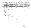
- zeigt eine erfindungsgemässe Einrichtung mit einem im Querschnitt dargestellten Deckenelement und schematisch dargestellten Leitungen.
- Fig. 1
- shows an inventive device with a ceiling element shown in cross section and schematically illustrated lines.
Ein knapp unter einer Raumdecke 1, welche z.B. aus Beton besteht, aufgehängtes Deckenelement 2 weist eine dreiteilige Deckenplatte 3 auf sowie eine Wanne 4, die eine als Lochplatte ausgebildete Bodenplatte 5 umfasst. Zusammen mit Seitenwänden 6, 7 umschliessen die Deckenplatte 3 und die Wanne 4 einen Innenraum, der durch von der Deckenplatte nach unten ragende Zwischenwände 8, 9 in drei nebeneinanderliegende Abschnitte 10, 11a, 11b unterteilt ist. Der mittlere Abschnitt 10 ist mit einer Kühlluftzuführung verbunden und weist eine oberhalb der Bodenplatte 5 angeordnete Kühlwand 6 auf, welche mit Mikrolöchern versehen ist und den Kühlluftstrom in den unter dem Deckenelement 2 liegenden Raum beschränkt.A just below a
In den seitlichen Abschnitten 11a,b sind jeweils zwei parallele untere wärmeleitschienen 12a;b, 13a;b angeordnet, die mit der Oberseite der Bodenplatte 4 verklebt sind sowie jeweils eine obere Wärmeleitschiene 14a;b, welche mit der Unterseite der Deckenplatte 3 verklebt ist. Die Wärmeleitschienen 12a,b, 13a,b, 14a,b können aus Aluminium bestehen. Sie weisen Führungen auf, in die ein Rohr, z.B. aus Kupfer, eingepresst ist, das - in dieser Reihenfolge - durch die Wärmeleitschienen 12a, 13a, 13b, 12b und 14a, 14b, läuft. Ein erster Teil des Rohres, der durch die unteren Wärmeleitschienen 12a, 13a, 13b, 12b gezogen ist, bildet einen ersten Leitungsabschnitt 15, der thermisch eng an die Bodenplatte 4 gekoppelt ist, deren Unterseite eine Raumaustauschfläche 16 zum Wärmeaustausch mit dem darunterliegenden Raum, vor allem durch Strahlung und Konvektion, bildet. Ein stromabwärts anschliessender zweiter Teil, der durch die oberen Wärmeleitschienen 14a, 14b gezogen ist, bildet dagegen einen zweiten Leitungsabschnitt 17, der thermisch eng an die Deckenplatte 3 gekoppelt ist, deren Oberseite eine Deckenaustauschfläche 18 bildet, die, ebenfalls durch Strahlung und Konvektion, Wärme mit der Raumdecke 1 austauscht. Das Rohr bildet auch Verbindungsleitungen zwischen den Wärmeleitschienen, die in Fig. 1 schematisch als vorneliegend (durchgezogen) und als hintenliegend (gestrichelt) angedeutet sind. In den seitlichen Abschnitten 11a,b sind Matten 19a;b angeordnet, die die entsprechenden Teile der Bodenplatte 4 mit den unteren Wärmeleitschienen 12a, 13a bzw. 12b, 13b bedecken. Sie dienen einerseits der Lärmdämpfung, andererseits bilden sie wärmedämmende Schichten, welche die Deckenplatte 3 mit der Deckenaustauschfläche 18 thermisch weitgehend von der Bodenplatte 4 mit der Raumaustauschfläche 16 entkoppeln.Two parallel lower heat conducting rails 12a, b, 13a, b which are glued to the upper side of the
Der Anfang des ersten Leitungsabschnitts 15 ist an einen ersten Ausgang eines Dreiwegventils 20 angeschlossen, dessen Eingang über ein Kühlregulierventil 21 mit einem Kühlvorlauf 22 verbunden ist und parallel dazu über ein Heizregulierventil 23 mit einem Heizvorlauf 24, während das Ende des zweiten Leitungsabschnitts 17 mit einem Kühlrücklauf 25 und parallel dazu mit einem Heizrücklauf 26 verbunden ist. Von einem zweiten Ausgang des Dreiwegventils 20 führt eine Ueberbrückungleitung 27 unter Umgehung des ersten Leitungsabschnitts 15, zu dem sie parallel liegt, d.h. ohne thermische Kopplung an die Raumaustauschfläche 16, direkt zum Anfang des zweiten Leitungsabschnitts 17.The beginning of the first line section 15 is connected to a first output of a three-
Im Kühlbetrieb ist das Dreiwegventil 20 während einer Betriebsphase, in welcher der Raum benutzt wird, also gewöhnlich während des Tages, so eingestellt, dass sein Eingang mit dem ersten Ausgang verbunden ist, d.h. die vom Kühlvorlauf 22 über das Kühlregulierventil 21 zufliessende Kühlflüssigkeit ausschliesslich zum Anfang des ersten Leitungsabschnitts 15 geleitet wird und denselben, d.h. die unteren wärmeleitschienen 12a, 13a, 13b, 12b durchströmt, und erst anschliessend den zweiten Leitungsabschnitt 17, d.h. die oberen Wärmeleitschienen 14a, 14b und dann zum Kühlrücklauf 25 gelangt (gerade Pfeile). Mit dieser Schaltung werden sowohl die Raumaustauschfläche 16 als auch die Deckenaustauschfläche 18 gekühlt und der Raum auch dann kühl gehalten, wenn die Wärmeabgabe von Personen und Geräten in demselben verhältnismässig hoch ist. Da die Raumdecke 1 vorgekühlt ist und sich während der Betriebsphase nur langsam erwärmt, nimmt die Kühlflüssigkeit jedoch im zweiten Leitungsabschnitt 17 im allgemeinen nicht viel Wärme auf. Besonders zu Beginn der Betriebsphase ist die Wärmeaufnahme sehr gering, im weiteren Verlauf der Betriebsphase steigt sie dann etwas an. Das Kühlregulierventil 21 kann je nach Kühlbedarf weiter oder weniger weit offen sein.In the cooling mode, the three-
Während einer Zwischenphase, gewöhnlich während der Nacht, ist das Dreiwegventil 20 dagegen so eingestellt, dass sein Eingang mit dem zweiten Ausgang verbunden ist, d.h. die vom Kühlvorlauf 22 über das Kühlregulierventil 21 zufliessende Kühlflüssigkeit über die Ueberbrückungsleitung 27 ausschliesslich direkt zum Anfang des zweiten Leitungsabschnittes 17 geleitet wird und denselben, d.h. die oberen wärmeleitschienen 14a, 14b durchströmt und dann zum Kühlrücklauf 2.5 geleitet wird (gewellte Pfeile). Der erste Leitungsabschnitt 15 wird vom Kühlmittel nicht durchströmt. Es wird daher praktisch nur die Deckenaustauschfläche 18 gekühlt, nicht aber die Raumaustauschfläche 16. Daher wird zwar die Raumdecke 1 vorgekühlt, aber eine unerwünschte Unterkühlung des zu dieser Zeit gewöhnlich thermisch nicht belasteten Raumes tritt zuverlässig nicht ein. Wiederum kann das Kühlregulierventil 21 je nach Kühlbedarf weiter oder weniger weit offen sein.On the other hand, during an intermediate phase, usually during the night, the three-
Statt Kühlmittel kann auch über das Heizregulierventil 23 Heizmittel vom Heizvorlauf 24 durch das Deckenelement 2 geleitet werden, das schliesslich in den Heizrücklauf 26 fliesst. Dabei sind die gleichen Betriebsweisen möglich wie für den Kühlbetrieb beschrieben und können die gleichen Vorteile erzielt werden.Instead of coolant can be passed through the Heizregulierventil 23 heating means from the
Es sind natürlich verschiedene Abweichungen vom beschriebenen Ausführungsbeispiel möglich, ohne dass der Bereich der Erfindung verlassen würde. So kann auch der mit der Deckenaustauschfläche thermisch gekoppelte zweite Leitungsabschnitt auf den Kühlmittelvorlauf folgen und der an die Raumaustauschfläche gekoppelte überbrückbare erste Leitungsabschnitt stromabwärts an denselben anschliessen. Das Dreiwegventil und die Regulierventile können auch zwischen dem Deckenelement und den Rückläufen angeordnet sein. Heiz- und Kühlkreis können, mit Verdopplung des Dreiwegventils, bis knapp vor das Deckenelement oder, wenn ein separates Rohr vorgesehen ist, das im Deckenelement z-B. durch parallele zweite Führungen in den Wärmeleitschienen läuft, überhaupt getrennt sein oder sie können im Gegenteil schon knapp vor dem Kühlvorlauf und Heizvorlauf durch ein weiteres Dreiwegventil, dessen zwei Eingänge mit den Vorläufen verbunden sind, zusammengeführt sein, mit einem einzigen nachgeordneten Regulierventil. Die Einrichtung kann auch mehrere Deckenelemente aufweisen, deren erste Leitungsabschnitte und zweite Leitungsabschnitte jeweils parallel durchströmt werden.Of course, various deviations from the described embodiment are possible without departing from the scope of the invention. Thus, the second line section, which is thermally coupled to the ceiling replacement surface, can also follow the coolant supply and connect the bridgeable first line section coupled to the room exchange surface to the same downstream. The three-way valve and the regulating valves can also be arranged between the ceiling element and the return lines. Heating and cooling circuit can, with doubling of the three-way valve, to just before the ceiling element or, if a separate pipe is provided in the ceiling element z-B. by parallel second guides in the heat pipes runs, be separated at all or they can on the contrary already be brought together just before the cooling flow and heating by another three-way valve whose two inputs are connected to the headers, with a single downstream regulating. The device may also have a plurality of ceiling elements, the first line sections and second line sections are respectively flowed through in parallel.
- 11
- Raumdeckeceiling
- 22
- Deckenelementceiling element
- 33
- Deckenplatteceiling tile
- 44
- Wannetub
- 55
- Bodenplattebaseplate
- 6, 76, 7
- Seitenwändeside walls
- 8, 98, 9
- Zwischenwändepartitions
- 10, 11a,b10, 11a, b
- Abschnittesections
- 12a,b12a, b
- WärmeleitschienenThermal conduction
- 13a,b13a, b
- WärmeleitschienenThermal conduction
- 14a,b14a, b
- WärmeleitschienenThermal conduction
- 1515
- erster Leitungsabschnittfirst line section
- 1616
- RaumaustauschflächeRoom exchange surface
- 1717
- zweiter Leitungsabschnittsecond line section
- 1818
- DeckenaustauschflächeCeiling exchange surface
- 19a,b19a, b
- MattenMats
- 2020
- DreiwegventilThree-way valve
- 2121
- KühlregulierventilKühlregulierventil
- 2222
- Kühlvorlaufcooling flow
- 2323
- HeizregulierventilHeizregulierventil
- 2424
- HeizvorlaufHeizvorlauf
- 2525
- KühlrücklaufCooling return
- 2626
- HeizrücklaufHeizrücklauf
- 2727
- UeberbrückungsleitungUeberbrückungsleitung
Claims (6)
Priority Applications (1)
| Application Number | Priority Date | Filing Date | Title |
|---|---|---|---|
| EP06011466A EP1862742A1 (en) | 2006-06-02 | 2006-06-02 | Room air conditioning device and method for its operation |
Applications Claiming Priority (1)
| Application Number | Priority Date | Filing Date | Title |
|---|---|---|---|
| EP06011466A EP1862742A1 (en) | 2006-06-02 | 2006-06-02 | Room air conditioning device and method for its operation |
Publications (1)
| Publication Number | Publication Date |
|---|---|
| EP1862742A1 true EP1862742A1 (en) | 2007-12-05 |
Family
ID=37188985
Family Applications (1)
| Application Number | Title | Priority Date | Filing Date |
|---|---|---|---|
| EP06011466A Withdrawn EP1862742A1 (en) | 2006-06-02 | 2006-06-02 | Room air conditioning device and method for its operation |
Country Status (1)
| Country | Link |
|---|---|
| EP (1) | EP1862742A1 (en) |
Cited By (4)
| Publication number | Priority date | Publication date | Assignee | Title |
|---|---|---|---|---|
| DE202008012683U1 (en) | 2008-09-24 | 2010-02-25 | Lindner Ag | Device for conditioning a room |
| CH707247A1 (en) * | 2012-11-29 | 2014-05-30 | Barcol Air | A method for heating or cooling a room and heating and cooling ceiling for performing the method. |
| EP2966370A1 (en) | 2014-06-17 | 2016-01-13 | Barcol-Air Group AG | Method for cooling or heating a space |
| EP2995871A1 (en) | 2014-09-12 | 2016-03-16 | Barcol-Air Group AG | Ceiling element and heating and cooling ceiling |
Citations (4)
| Publication number | Priority date | Publication date | Assignee | Title |
|---|---|---|---|---|
| EP1279899A2 (en) * | 2001-07-26 | 2003-01-29 | LUK Agentur für Luft- und Klimasysteme AG | Device for cooling a room |
| EP1355113A1 (en) * | 2002-04-15 | 2003-10-22 | Harry Gmür | Heating and cooling system for building |
| EP1422482A1 (en) * | 2002-11-22 | 2004-05-26 | LUK Agentur für Luft- und Klimasysteme AG | Device for heating and cooling a room, ceiling element for this device and method for its operation |
| DE10346503A1 (en) * | 2003-10-02 | 2005-04-21 | Stulz Gmbh Klimatechnik | Heating/cooling appliance for rooms e.g. offices has medium duct system with two sections for strong thermal coupling to ceiling or wall, and to room atmosphere |
-
2006
- 2006-06-02 EP EP06011466A patent/EP1862742A1/en not_active Withdrawn
Patent Citations (4)
| Publication number | Priority date | Publication date | Assignee | Title |
|---|---|---|---|---|
| EP1279899A2 (en) * | 2001-07-26 | 2003-01-29 | LUK Agentur für Luft- und Klimasysteme AG | Device for cooling a room |
| EP1355113A1 (en) * | 2002-04-15 | 2003-10-22 | Harry Gmür | Heating and cooling system for building |
| EP1422482A1 (en) * | 2002-11-22 | 2004-05-26 | LUK Agentur für Luft- und Klimasysteme AG | Device for heating and cooling a room, ceiling element for this device and method for its operation |
| DE10346503A1 (en) * | 2003-10-02 | 2005-04-21 | Stulz Gmbh Klimatechnik | Heating/cooling appliance for rooms e.g. offices has medium duct system with two sections for strong thermal coupling to ceiling or wall, and to room atmosphere |
Cited By (7)
| Publication number | Priority date | Publication date | Assignee | Title |
|---|---|---|---|---|
| DE202008012683U1 (en) | 2008-09-24 | 2010-02-25 | Lindner Ag | Device for conditioning a room |
| WO2010034498A2 (en) * | 2008-09-24 | 2010-04-01 | Lindner Ag | Device for controlling the climate of a room |
| WO2010034498A3 (en) * | 2008-09-24 | 2010-06-24 | Lindner Ag | Device for controlling the climate of a room with two independent fluid circuits |
| CH707247A1 (en) * | 2012-11-29 | 2014-05-30 | Barcol Air | A method for heating or cooling a room and heating and cooling ceiling for performing the method. |
| EP2743596A1 (en) * | 2012-11-29 | 2014-06-18 | MWH Barcol-Air AG | Method for heating or cooling a room and heating and cooling ceiling for carrying out the method |
| EP2966370A1 (en) | 2014-06-17 | 2016-01-13 | Barcol-Air Group AG | Method for cooling or heating a space |
| EP2995871A1 (en) | 2014-09-12 | 2016-03-16 | Barcol-Air Group AG | Ceiling element and heating and cooling ceiling |
Similar Documents
| Publication | Publication Date | Title |
|---|---|---|
| DE60211925T2 (en) | FLUID DISTRIBUTION DEVICE | |
| DE3247302C2 (en) | ||
| EP1568828A1 (en) | Set of prefabricated elements, especially for ceilings, floors and walls as well as building elements for making a set of prefabricated elements | |
| EP1862742A1 (en) | Room air conditioning device and method for its operation | |
| DE3214775C2 (en) | Device for transferring heat-carrying fluid from a supply line of a district heating power plant to a consumer | |
| WO2009147136A1 (en) | Line arrangement for tempering two tempering circuits of buildings | |
| DE102018217228A1 (en) | Drinking water distribution module for connecting a base pipe to a main circulation pipe | |
| EP4382814A1 (en) | Flow device for retrofitting a heating system and a heating system | |
| DE2605994C2 (en) | Water heating system | |
| DE102009035285A1 (en) | Vehicle with a cooling system for cooling a component to be warmed up and an air conditioning system | |
| DE102015114469B3 (en) | System for guiding cold water, method for cooling a cold water line and use of a line for guiding cold water | |
| DE10158054B4 (en) | Ceiling element for the production of a Klimadecke, arrangement for the air conditioning of a room, and method for mounting a Klimadecke | |
| EP1541934B1 (en) | Cooling element, cooling device and operating method therefor | |
| EP3988881B1 (en) | Method for operating a heat transfer assembly | |
| DE69814594T2 (en) | A LUBRICATION CIRCUIT SYSTEM | |
| DE102007031084B4 (en) | Sewer pipe with heat exchanger element | |
| DE102007040570A1 (en) | Rail vehicle with air conditioning heat exchanger for heat recovery | |
| EP1422482B1 (en) | Device for heating and cooling a room, ceiling element for this device and method for its operation | |
| DE102019135548A1 (en) | Drinking water pipe module for drinking water circulation when the draw-off points are closed | |
| EP1279899A2 (en) | Device for cooling a room | |
| DE102015203293B4 (en) | building | |
| DE29808529U1 (en) | Installation module | |
| EP3705785A1 (en) | Connection station for liquid media for at least one building section, in particular for a living room | |
| EP0644380A1 (en) | Device for controlling the inside temperature of buildings | |
| DE202017104448U1 (en) | building |
Legal Events
| Date | Code | Title | Description |
|---|---|---|---|
| PUAI | Public reference made under article 153(3) epc to a published international application that has entered the european phase |
Free format text: ORIGINAL CODE: 0009012 |
|
| AK | Designated contracting states |
Kind code of ref document: A1 Designated state(s): AT BE BG CH CY CZ DE DK EE ES FI FR GB GR HU IE IS IT LI LT LU LV MC NL PL PT RO SE SI SK TR |
|
| AX | Request for extension of the european patent |
Extension state: AL BA HR MK YU |
|
| AKX | Designation fees paid | ||
| REG | Reference to a national code |
Ref country code: DE Ref legal event code: 8566 |
|
| STAA | Information on the status of an ep patent application or granted ep patent |
Free format text: STATUS: THE APPLICATION IS DEEMED TO BE WITHDRAWN |
|
| 18D | Application deemed to be withdrawn |
Effective date: 20080606 |