EP1862706A1 - Roller screw - Google Patents
Roller screw Download PDFInfo
- Publication number
- EP1862706A1 EP1862706A1 EP06715116A EP06715116A EP1862706A1 EP 1862706 A1 EP1862706 A1 EP 1862706A1 EP 06715116 A EP06715116 A EP 06715116A EP 06715116 A EP06715116 A EP 06715116A EP 1862706 A1 EP1862706 A1 EP 1862706A1
- Authority
- EP
- European Patent Office
- Prior art keywords
- roller
- rollers
- screw shaft
- screw
- rolling surface
- Prior art date
- Legal status (The legal status is an assumption and is not a legal conclusion. Google has not performed a legal analysis and makes no representation as to the accuracy of the status listed.)
- Granted
Links
- 238000005096 rolling process Methods 0.000 claims abstract description 126
- 238000000034 method Methods 0.000 claims description 7
- 125000006850 spacer group Chemical group 0.000 claims description 7
- 230000004323 axial length Effects 0.000 claims description 3
- 230000007704 transition Effects 0.000 description 8
- 239000004575 stone Substances 0.000 description 2
- 238000004804 winding Methods 0.000 description 2
- 230000000694 effects Effects 0.000 description 1
- 238000010438 heat treatment Methods 0.000 description 1
- 230000002452 interceptive effect Effects 0.000 description 1
- 238000003754 machining Methods 0.000 description 1
- 239000002184 metal Substances 0.000 description 1
Images





Classifications
-
- F—MECHANICAL ENGINEERING; LIGHTING; HEATING; WEAPONS; BLASTING
- F16—ENGINEERING ELEMENTS AND UNITS; GENERAL MEASURES FOR PRODUCING AND MAINTAINING EFFECTIVE FUNCTIONING OF MACHINES OR INSTALLATIONS; THERMAL INSULATION IN GENERAL
- F16H—GEARING
- F16H25/00—Gearings comprising primarily only cams, cam-followers and screw-and-nut mechanisms
- F16H25/18—Gearings comprising primarily only cams, cam-followers and screw-and-nut mechanisms for conveying or interconverting oscillating or reciprocating motions
- F16H25/20—Screw mechanisms
- F16H25/22—Screw mechanisms with balls, rollers, or similar members between the co-operating parts; Elements essential to the use of such members
-
- F—MECHANICAL ENGINEERING; LIGHTING; HEATING; WEAPONS; BLASTING
- F16—ENGINEERING ELEMENTS AND UNITS; GENERAL MEASURES FOR PRODUCING AND MAINTAINING EFFECTIVE FUNCTIONING OF MACHINES OR INSTALLATIONS; THERMAL INSULATION IN GENERAL
- F16H—GEARING
- F16H25/00—Gearings comprising primarily only cams, cam-followers and screw-and-nut mechanisms
- F16H25/18—Gearings comprising primarily only cams, cam-followers and screw-and-nut mechanisms for conveying or interconverting oscillating or reciprocating motions
- F16H25/20—Screw mechanisms
- F16H25/22—Screw mechanisms with balls, rollers, or similar members between the co-operating parts; Elements essential to the use of such members
- F16H25/2247—Screw mechanisms with balls, rollers, or similar members between the co-operating parts; Elements essential to the use of such members with rollers
-
- F—MECHANICAL ENGINEERING; LIGHTING; HEATING; WEAPONS; BLASTING
- F16—ENGINEERING ELEMENTS AND UNITS; GENERAL MEASURES FOR PRODUCING AND MAINTAINING EFFECTIVE FUNCTIONING OF MACHINES OR INSTALLATIONS; THERMAL INSULATION IN GENERAL
- F16H—GEARING
- F16H25/00—Gearings comprising primarily only cams, cam-followers and screw-and-nut mechanisms
- F16H25/18—Gearings comprising primarily only cams, cam-followers and screw-and-nut mechanisms for conveying or interconverting oscillating or reciprocating motions
- F16H25/20—Screw mechanisms
- F16H25/22—Screw mechanisms with balls, rollers, or similar members between the co-operating parts; Elements essential to the use of such members
- F16H25/2247—Screw mechanisms with balls, rollers, or similar members between the co-operating parts; Elements essential to the use of such members with rollers
- F16H2025/2271—Screw mechanisms with balls, rollers, or similar members between the co-operating parts; Elements essential to the use of such members with rollers with means for guiding circulating rollers
-
- Y—GENERAL TAGGING OF NEW TECHNOLOGICAL DEVELOPMENTS; GENERAL TAGGING OF CROSS-SECTIONAL TECHNOLOGIES SPANNING OVER SEVERAL SECTIONS OF THE IPC; TECHNICAL SUBJECTS COVERED BY FORMER USPC CROSS-REFERENCE ART COLLECTIONS [XRACs] AND DIGESTS
- Y10—TECHNICAL SUBJECTS COVERED BY FORMER USPC
- Y10T—TECHNICAL SUBJECTS COVERED BY FORMER US CLASSIFICATION
- Y10T74/00—Machine element or mechanism
- Y10T74/19—Gearing
- Y10T74/19642—Directly cooperating gears
- Y10T74/19698—Spiral
- Y10T74/19702—Screw and nut
- Y10T74/19744—Rolling element engaging thread
-
- Y—GENERAL TAGGING OF NEW TECHNOLOGICAL DEVELOPMENTS; GENERAL TAGGING OF CROSS-SECTIONAL TECHNOLOGIES SPANNING OVER SEVERAL SECTIONS OF THE IPC; TECHNICAL SUBJECTS COVERED BY FORMER USPC CROSS-REFERENCE ART COLLECTIONS [XRACs] AND DIGESTS
- Y10—TECHNICAL SUBJECTS COVERED BY FORMER USPC
- Y10T—TECHNICAL SUBJECTS COVERED BY FORMER US CLASSIFICATION
- Y10T74/00—Machine element or mechanism
- Y10T74/19—Gearing
- Y10T74/19642—Directly cooperating gears
- Y10T74/19698—Spiral
- Y10T74/19702—Screw and nut
- Y10T74/19744—Rolling element engaging thread
- Y10T74/19781—Non-recirculating rolling elements
- Y10T74/19791—Cylindrical or quasi-cylindrical roller element [e.g., inclined roller, etc.]
Definitions
- a ball screw having balls capable of rolling between a screw shaft and a nut.
- Such a ball screw has been in the actual use in a positioning mechanism of a machine tool/robot, a feeding mechanism, a steering gear of a vehicle and the like as it allows reduction of the friction factor in rolling the screw shaft relative to the nut, as compared with a sliding-contact type screw.
- a roller screw using rollers as rolling elements instead of balls which is disclosed in the patent document 1, for example.
- a screw shaft has a roller rolling surface spirally formed on the outer surface thereof and a nut also has a roller rolling surface spirally formed on the inner surface thereof to face the roller rolling surface of the screw shaft.
- plural rollers as rolling elements.
- roller screw as described above was devised, however, it has not yet been in the actual use.
- the inventors tried developing the roller screw based on the idea of rotary bearing using rollers as rolling elements.
- roller screw In a rotary bearing, there are plural rollers arranged annularly in one plane and the rotation axes of the respective rollers are directed toward the center of an annular rolling path.
- the roller screw can be thought of as a roller bearing with a lead. From this point of view, the roller screw was designed as the rotary bearing having a rolling path with a lead and rollers 32 were arranged in the spiral rolling path with lead.
- Figs. 20(A) to 20(D) illustrate the transition of the rotation axis of a roller arranged in a spiral roller rolling path with a lead
- Fig. 20(A) is a perspective view of rollers in the rolling path
- Fig. 20(B) is a perspective view illustrating the transition of the rotation axis
- Fig. 20(C) is a front view illustrating the transition of the rotation axis
- Fig. 20(D) is a side view illustrating the transition of the rotation axis).
- the inventors have taken note of the rotation axis of each roller arranged in the rolling path of such a problematic roller screw and found that the rotation axis 32a of the roller 32 does not cross the center line 31a of the screw shaft 31 and as the roller 32 moves, the point P on the rotation axis 32a of the roller 32 moves on a coil-shaped track with the center line 31a of the screw shaft 31 as its center. They have also found that when a lead is provided in the rolling path, the rotation axis 32a of each roller 32 does not cross the center line 31a of the screw shaft 31 (in other words, the roller is skewed from the beginning), which consequently prevents smooth movement of the roller 32.
- the invention of claim 1 provides a roller screw having: a screw shaft (1) having a roller rolling surface (1a) spirally formed with a lead on an outer surface thereof; a nut (2) having a roller rolling surface (2a) spirally formed on an inner surface thereof to face the roller rolling surface (1a) of the screw shaft (1); and a plurality of rollers (4) arranged in a rolling path (3) between the roller rolling surface (1a) of the screw shaft (1) and the roller rolling surface (2a) of the nut (2) and moving around the screw shaft (1) while rotating on respective rotation axes of the rollers, each of the rotation axes (4a) of the rollers (4) substantially crossing a center line (1b) of the screw shaft (1), thereby solving the above-mentioned problems.
- the feature that the rotation axis of each roller substantially crosses the center line of the screw shaft includes a case where the rotation axis of the roller crosses the center line of the screw shaft and a case where the rotation axis of the roller is displaced from (extends off) the center line of the screw shaft slightly enough to allow smooth movement of the roller.
- the invention of claim 2 is characterized in that in the roller screw according to claim 1, the rollers (4) move around the screw shaft (1) in such a manner that an angle ( ⁇ ) formed by a rotation axis (4a) of each of the rollers (4) and a normal (9) extending from a center of the roller (4) to the center line (1b) of the screw shaft (1) is kept constant.
- each of the rollers (4) has a cylindrical shape.
- the invention of claim 5 is characterized in that in the roller screw according to claim 4, the rollers (4) are cross-arranged in the rolling path (3) in such a manner that the rotation axes (4a) of adjacent two of the rollers (4) are orthogonal to each other when seen in a moving direction of the rollers (4).
- the invention of claim 6 is characterized in that in the roller screw according to claim 4 or 5, an axial length L and an outer diameter D of each of the rollers (4) satisfy a relation of L/D ⁇ 1.
- the invention of claim 8 provides a roller circulating method of a roller screw having a plurality of rollers (4) arranged in a rolling path (3) between a roller rolling surface (1a) spirally formed on an outer surface of a screw shaft (1) and a roller rolling surface (2a) spirally formed on an inner surface of a nut (2) to face the roller rolling surface (1a) of the screw shaft , the rollers (4) moving around the screw shaft (1) while rotating on respective rotation axes (4) thereof, and each of the rotation axes (4a) of the rollers substantially crossing a center line (1b) of the screw shaft (1), thereby solving the above-mentioned problems.
- the rotation axes of the rollers can be directed toward the center line of the screw shaft.
- the rotation axes of the rollers cross the center line of the screw shaft (in other words, the rollers arranged in the rolling path are not skewed from the beginning). Therefore, smooth movement of the rollers is allowed.
- Each roller 4 revolves around the screw shaft 1 while rotating on its axis.
- An essential feature of the present invention is that when the roller 4 revolves around the screw shaft 1 while rotating on its axis, the rotation axis of the roller 4 crosses the center line of the screw shaft 1 as illustrated in Figs. 1 to 5. Even if the position of the roller 4 varies from Fig. 1 to Fig. 5, the rotation axis 4a of the roller 4 always crosses the center line 1b of the screw shaft 1. The center line 1b of the screw shaft 1 coincides with the center line of revolution orbit of the roller 4.
- the roller 4 revolves around the screw shaft 1 while keeping an angle ⁇ formed by the rotation axis 4a and the normal 9 extending from the center of the roller 4 to the center line 1b of the screw shaft 1 constant, or constant at 45° in this embodiment. For this reason, the angle formed by the center line of the screw shaft 1 and the rotation axis of the roller 4 is also kept constant at 45°.
- Fig. 7 illustrates a roller screw seen in the axial direction of the screw shaft 1.
- the rotation axis 4a of the roller 4 crosses the center line 1b of the screw shaft 1.
- the rotation axes 4a of all rollers 4 revolving around the screw shaft 1 cross the center line 1b of the screw shaft.
- the rotation axes 4a of the plural rollers 4 extend in all directions from the center line 1b of the screw shaft 1.
- Figs. 8 and 9 are detailed views each illustrating a roller 4 rolling on the roller rolling surface 1a of the screw shaft 1.
- the roller 4 rolls on the roller rolling surface 1a which is a one-side wall surface of the groove 6 of v-shaped cross section.
- a side surface 4b of the roller 4 comes in contact with the other-side wall surface 1c of the groove 6 and thereby the attitude of the roller 4 varies gradually. Even if the position of the roller 4 varies, the rotation axis 4a of the roller 4 extends toward the center line 1b of the screw shaft 1.
- Figs. 10 and 11 are detailed views each illustrating a roller 4 rolling on the roller rolling surface 2a of the nut 2.
- the roller 4 rolls on the roller rolling surface 2a which is a one-side wall surface of the groove 7 of v-shaped cross section.
- the side surface 4b of the roller 4 comes in contact with the other-side wall surface 2b of the groove 7 and thereby the attitude of the roller 4 varies gradually so that the rotation axis 4a of the roller 4 extends toward the center line 1b of the screw shaft 1.
- the ratio of the axial length L to the diameter D of the roller 4 meets L/D ⁇ 1. This is for preventing the side surface 4b of the roller 4 from interfering with the wall surface of the rolling path 3, as is the case with a roller held in an annular rolling path of the rotary bearing.
- the L/D value also depends on a lead of the screw shaft 1. As the lead of the screw shaft 1 is larger, the L/D value needs to be smaller.
- the roller 4 indicated by the broken line has its rotation axis 4c not extending toward the center line 1b of the screw shaft 1 and therefore, the roller 4 is arranged while being skewed from the beginning. With this arrangement, if the roller 4 moves in the direction of the arrow, the roller 4 comes into collision with the wall surfaces of the screw shaft 1 and the nut 2, which results in application of a large load on the roller 4.
- Fig. 13 illustrates slips caused in a roller 4 arranged in the conventional way. Slips caused in the roller 4 are separated into one slip S1 which is caused similarly in the rotary bearing and the other slip S2 which is caused by a lead angle.
- the slip S1 caused like in the rotary bearing results from a circumference difference between the inner side and the outer side.
- An amount of slip S1 depends on a relation between the size of the roller 4 and the RCD of the roller 4. As the RCD is larger relative to the length of the roller 4, the slip amount becomes smaller, while as the RCD is smaller, the slip amount becomes larger.
- the slip S2 due to a lead angle is prevented from causing skew though the slip itself remains to occur.
- the slip S1 like in the rotary bearing also remains and is hard to remove completely as it is caused by a circumference difference between the inner side and the outer side.
- the rotation axis 4a of the roller 4 is directed toward the center line 1b of the screw shaft 1 and an angle formed by the rotation axis 4a of the roller 4 and the center line 1b of the screw shaft 1 is set to 45°.
- the roller is cut along the cross section including the rotation axis 4a of the roller 4 and the center line 1b of the screw shaft 1 to obtain an initial contact line 4d of the roller 4 in the cross section.
- This initial contact line 4d is developed (i.e., swept) spirally in the three-dimensional space to obtain a band-type initial contact surface 13 of the screw shaft as illustrated in Fig. 14(C).
- Fig. 15 (A) illustrates the initial contact surface 13 of the screw shaft 1
- Fig. 16(A) illustrates an initial surface 14 of the nut 2 obtained likewise.
- the roller 4 is arranged again on the initial contact surface 13 of the screw shaft 1 in such a manner that the rotation axis 4a of the roller 4 crosses the center line 1b of the screw shaft 1 and the angle formed by the rotation axis 4a of the roller 4 and the center line 1b of the screw shaft 1 is 45°. Then, as the initial contact surface 13 of the screw shaft 1 has a lead, the roller 4 comes into contact or interferes with the initial contact surface of the screw shaft 1 at the position slightly displaced from the aforementioned initial contact line 4d.
- Fig. 15(B) illustrates a portion 15 where the roller 4 interferes with the initial contact surface 13 of the screw shaft 1
- Fig. 16 (B) illustrates a portion 16 where the roller 4 interferes with the initial contact surface 14 of the nut 2.
- the portions 15 and 16 of the screw shaft 1 and the nut 2, respectively, are differently shaped because the roller 4 is into contact with the screw shaft 1 in such a manner that a large circle and a small circle are in contact at their outer surfaces, while the roller 4 is in contact with the nut 2 in such a manner that the outer surface of a small circle is in contact with the inner surface of a large circle.
- the interference portions are shaped like rectangle and hourglass on three dimensional CAD, however, from eye observation, they are seen like lines.
- the portions of the largest interference are secondary contact lines 17 and 18, and their positions are specified.
- the specified secondary contact line 17 and 18 are developed spirally in the three dimensional space like interference grinding.
- designing of the roller rolling surfaces 1a and 2a of the screw shaft 1 and the nut 2 are completed.
- the rotation axis 4a of the roller 4 arranged between the designed roller rolling surfaces 1a and 2a crosses the center line 1b of the screw shaft 1.
- the roller 4 is in contact with the roller rolling surfaces 1a and 2a of the screw shaft 1 and the nut 2 at the positions of secondary contact lines 17 and 18, respectively.
- each roller rolling surface (1a, 2a) As designed above.
- a grinding stone of diameter equal to that of a roller is used and arranged to have its center line crossing the center line of the screw shaft.
- the grinding stone is used to grind the roller rolling surface.
- the roller rolling surface of complex or multiple shapes described above is completed.
- the roller rolling surface may be machined by cutting or rolling into a rough-shape surface, subjecting the surface to heat treatment before cutting the surface into the above-described multiple-shape surface by a hard metal chip and finally, finishing the surface by finisher.
- Figs. 17 and 18 illustrate an example of a roller screw according to the above-described embodiment which is provided with a circulation path.
- an unloaded return path 19 is provided to return rollers 4 on the rolling path 3. After a roller 4 rolls from one end of the rolling path 3 to the other, the roller 4 moves along the unloaded return path 19 and returns several windings backward to the one end of the rolling path 3.
- the unloaded return path 19 includes a straight-line path 20 at the central part and direction change paths 21 at both ends.
- a through hole is formed extending in parallel with the center line 1b of the screw shaft 1, and inserted into this through hole is a pipe-shaped straight-line portion 22.
- the straight-line path 20 is formed having a straight track and a box-shaped cross section.
- the straight-line path 20 extends straight and in parallel with the center line 1b of the screw shaft 1.
- Each direction change path 21 extends in a curved or circular arc form.
- a direction change path component 23 At each of end faces in the axial direction of the nut 2, there is provided a direction change path component 23.
- the direction change path 21 is formed having a circular arc track and a box-shaped cross section.
- the direction change path component 23 is divided into an inner side component and an outer side component along the diagonal line of the box-shaped section of the direction change path 21.
- Fig. 19 illustrates another example of the roller circulation path.
- a U-shaped return pipe 25 is attached to the nut 2. This return pipe 25 is used to scoop each roller 4 which has rolled from one end of the rolling path 3 to the other end. The return pipe 25 then makes the roller 4 pass through the unloaded return path in the return pipe 25 to return the roller 4 several windings backward to the one end.
- rollers are not limited to cross arrangement in which adjacent two rollers are arranged with their axis lines orthogonal to each other and may be parallel arrangement in which adjacent two rollers are arranged with their axis lines parallel to each other.
- a roller is not necessarily cylindrical and may be a tapered roller. When the tapered roller is used, it is possible to reduce slips due to a circumference difference between the inner side and the outer side and thereby to allow smooth movement of the roller.
- the number of threads on the roller rolling surface may be one, two or three, or any number of threads may be provided on the roller rolling surface.
Landscapes
- Engineering & Computer Science (AREA)
- General Engineering & Computer Science (AREA)
- Mechanical Engineering (AREA)
- Transmission Devices (AREA)
Abstract
Description
- The present invention relates to a roller screw having rollers capable of rolling between a screw shaft and a nut.
- There is known a ball screw having balls capable of rolling between a screw shaft and a nut. Such a ball screw has been in the actual use in a positioning mechanism of a machine tool/robot, a feeding mechanism, a steering gear of a vehicle and the like as it allows reduction of the friction factor in rolling the screw shaft relative to the nut, as compared with a sliding-contact type screw.
- In these years, in order to increase an allowable load, there has been devised a roller screw using rollers as rolling elements instead of balls, which is disclosed in the
patent document 1, for example. In such a roller screw, a screw shaft has a roller rolling surface spirally formed on the outer surface thereof and a nut also has a roller rolling surface spirally formed on the inner surface thereof to face the roller rolling surface of the screw shaft. In a rolling path formed between the roller rolling surface of the screw shaft and the roller rolling surface of the nut, there are arranged plural rollers as rolling elements. When either the screw shaft or the nut is rotated, the rollers move (revolve) around the screw shaft while rotating on their axes.
[Patent Document 1]Japanese Patent Laid-open Publication No.11-210858 - Such a roller screw as described above was devised, however, it has not yet been in the actual use. In order to put this roller screw into practical use, the inventors tried developing the roller screw based on the idea of rotary bearing using rollers as rolling elements.
- In a rotary bearing, there are plural rollers arranged annularly in one plane and the rotation axes of the respective rollers are directed toward the center of an annular rolling path. Here, the roller screw can be thought of as a roller bearing with a lead. From this point of view, the roller screw was designed as the rotary bearing having a rolling path with a lead and
rollers 32 were arranged in the spiral rolling path with lead. - When the idea of rotary bearing was used as a basis to design a ball screw using as rolling elements balls capable of rolling in every direction, there occurred no problem. However, when the rolling elements used were rollers capable of rolling in only one direction, there occurred a problem that the rollers did not move smoothly (or in a worse situation, the rollers were locked and could not move), which problem was unforeseen in the case of the ball screw.
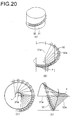
- Figs. 20(A) to 20(D) illustrate the transition of the rotation axis of a roller arranged in a spiral roller rolling path with a lead (Fig. 20(A) is a perspective view of rollers in the rolling path, Fig. 20(B) is a perspective view illustrating the transition of the rotation axis, Fig. 20(C) is a front view illustrating the transition of the rotation axis and Fig. 20(D) is a side view illustrating the transition of the rotation axis). The inventors have taken note of the rotation axis of each roller arranged in the rolling path of such a problematic roller screw and found that the
rotation axis 32a of theroller 32 does not cross thecenter line 31a of thescrew shaft 31 and as theroller 32 moves, the point P on therotation axis 32a of theroller 32 moves on a coil-shaped track with thecenter line 31a of thescrew shaft 31 as its center. They have also found that when a lead is provided in the rolling path, therotation axis 32a of eachroller 32 does not cross thecenter line 31a of the screw shaft 31 (in other words, the roller is skewed from the beginning), which consequently prevents smooth movement of theroller 32. - Description will now be made of the present invention. For ease in understanding the present invention, the reference numerals in accompanying drawings are added in parentheses to the following description. However, these are not for limiting the present invention to the embodiments illustrated in the drawings.
- The inventors have solved the above-mentioned problems by making the rotation axis of each roller in a rolling path cross the center line of the screw shaft even when the rolling path has a lead. Specifically, the invention of
claim 1 provides a roller screw having: a screw shaft (1) having a roller rolling surface (1a) spirally formed with a lead on an outer surface thereof; a nut (2) having a roller rolling surface (2a) spirally formed on an inner surface thereof to face the roller rolling surface (1a) of the screw shaft (1); and a plurality of rollers (4) arranged in a rolling path (3) between the roller rolling surface (1a) of the screw shaft (1) and the roller rolling surface (2a) of the nut (2) and moving around the screw shaft (1) while rotating on respective rotation axes of the rollers, each of the rotation axes (4a) of the rollers (4) substantially crossing a center line (1b) of the screw shaft (1), thereby solving the above-mentioned problems. - Here, the feature that the rotation axis of each roller substantially crosses the center line of the screw shaft includes a case where the rotation axis of the roller crosses the center line of the screw shaft and a case where the rotation axis of the roller is displaced from (extends off) the center line of the screw shaft slightly enough to allow smooth movement of the roller.
- The invention of
claim 2 is characterized in that in the roller screw according toclaim 1, the rollers (4) move around the screw shaft (1) in such a manner that an angle (θ) formed by a rotation axis (4a) of each of the rollers (4) and a normal (9) extending from a center of the roller (4) to the center line (1b) of the screw shaft (1) is kept constant. - The invention of
claim 3 is characterized in that in the roller screw according toclaim - The invention of claim 5 is characterized in that in the roller screw according to any one of
claims 1 to 3, each of the rollers (4) has a cylindrical shape. - The invention of claim 5 is characterized in that in the roller screw according to
claim 4, the rollers (4) are cross-arranged in the rolling path (3) in such a manner that the rotation axes (4a) of adjacent two of the rollers (4) are orthogonal to each other when seen in a moving direction of the rollers (4). - The invention of
claim 6 is characterized in that in the roller screw according toclaim 4 or 5, an axial length L and an outer diameter D of each of the rollers (4) satisfy a relation of L/D < 1. - The invention of
claim 7 is characterized in that in the roller screw according to any one ofclaims 1 to 6, a spacer (11) is provided between each adjacent two of the rollers (4) for supporting attitudes of the rollers (4) to make the rotation axes (4a) of the rollers (4) cross the center line (1b) of the screw shaft (1) substantially. - The invention of
claim 8 provides a roller circulating method of a roller screw having a plurality of rollers (4) arranged in a rolling path (3) between a roller rolling surface (1a) spirally formed on an outer surface of a screw shaft (1) and a roller rolling surface (2a) spirally formed on an inner surface of a nut (2) to face the roller rolling surface (1a) of the screw shaft , the rollers (4) moving around the screw shaft (1) while rotating on respective rotation axes (4) thereof, and each of the rotation axes (4a) of the rollers substantially crossing a center line (1b) of the screw shaft (1), thereby solving the above-mentioned problems. - According to the invention of
claim 1, even when the rolling path has a lead,'the rotation axes of the rollers cross the center line of the screw shaft (in other words, the rollers arranged in the rolling path are not skewed from the beginning). Therefore, the rollers are allowed to move smoothly. - According to the invention of
claim 2, smoother movement of the rollers is allowed. - According to the invention of
claim 3, the rotation axes of the rollers can be directed toward the center line of the screw shaft. - According to the invention of
claim 4, even if the rollers used are cylindrical rollers which are likely to slip and be skewed, the rollers are allowed to move smoothly. - According to the invention of claim 5, it is possible to obtain a roller screw with rollers taking loads in two axially opposite directions of the screw shaft, which roller screw is nearing practical use.
- According to the invention of
claim 6, it is possible to hold the rollers within the rolling path. - According to the invention of
claim 7, as a spacer holds the attitudes of each adjacent two rollers in such a manner that the rotation axes of the rollers cross the center line of the screw shaft, smoother movement of the rollers is allowed. - According to the invention of
claim 8, even when the rolling path has a lead, the rotation axes of the rollers cross the center line of the screw shaft (in other words, the rollers arranged in the rolling path are not skewed from the beginning). Therefore, smooth movement of the rollers is allowed. -
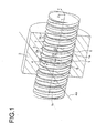
- Fig. 1 is a perspective view of a roller screw according to an embodiment of the present invention (with a nut taken in cross section).
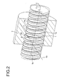
- Fig. 2 is a perspective view of the roller screw with the roller at a different position.
- Fig. 3 is a perspective view of the roller screw with the roller at another different position.
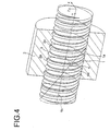
- Fig. 4 is a perspective view of the roller screw with the roller at yet another different position.
- Fig. 5 is a perspective view of the roller screw with the roller at yet another different position.
- Fig. 6 is a perspective view illustrating cross-arranged rollers.
- Fig. 7 is a view of a roller screw looking in the axial direction of the screw shaft.
- Fig. 8 is a detailed view of a roller rolling on a roller rolling surface of the screw shaft.
- Fig. 9 is a detailed view of a roller rolling on the roller rolling surface of the screw shaft.
- Fig. 10 is a detailed view of a roller rolling on a roller rolling surface of the nut.
- Fig. 11 is a detailed view of a roller rolling on the roller rolling surface of the nut.
- Fig. 12 is a conceptual view of a roller moving between the screw shaft and the nut.
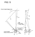
- Fig. 13 is a view illustrating slips of rollers arranged in the conventional way.
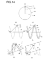
- Figs. 14 (A) to 14 (E) are views each illustrating a design method of a roller rolling surface.
- Figs. 15 (A) and 15 (B) are views each illustrating a design method of the roller rolling surface of the screw shaft.
- Figs. 16 (A) and 16 (B) are views each illustrating a design method of the roller rolling surface of the nut.
- Fig. 17 is a perspective view of a roller screw provided with a circulation path (end cap type).
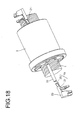
- Fig. 18 is a perspective view of a roller screw provided with a circulation path (end cap type).
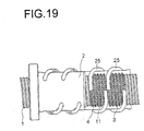
- Fig. 19 is a perspective view of a roller screw provided with a circulation path (return pipe type).
- Figs. 20(A) to 20(D) each illustrates the transition of the rotation axis of a roller arranged in a spiral rolling path with a lead (Fig. 20 (A) is a perspective view of rollers in the rolling path, Fig. 20 (B) is a perspective view of the transition of the rotation axis, Fig. 20 (C) is a front view of the transition of the rotation axis and Fig. 20 (D) is a side view of the transition of the rotation axis.
-
- 1 screw shaft
- 1a roller rolling surface
- 2 nut
- 2a roller rolling surface
- 3 rolling path
- 4 roller
- 4a rotation axis
- 4d initial contact line
- 9 normal
- 11 spacer
- 17, 18 secondary contact line
- With reference to the attached drawings, a roller screw according to an embodiment of the present invention will be described in detail below. In each figure, identical mechanical elements are indicated by identical reference numerals.
- Figs. 1 to 5 are perspective views of a roller screw (including a nut taken in cross section). A roller screw has a
screw shaft 1 having aroller rolling surface 1a spirally formed on its outer surface, and anut 2 having aroller rolling surface 2a spirally formed on its inner surface. Theroller rolling surface 1a of thescrew shaft 1 and theroller rolling surface 2a of thenut 2 face each other, and between theseroller rolling surfaces spiral rolling path 3. Here, acenter line 3a of thespiral rolling path 3 is indicated by a dash-dotted line. - The rolling
path 3 accommodates a plurality ofrollers 4 to allow them to roll therein (Figs. 1 to 5o illustrate only oneroller 4 for illustration of the movement of the roller). When thescrew shaft 1 is rotated relative to thenut 2, thenut 2 moves relatively and linearly in the axial direction of thescrew shaft 1 by a lead provided in theroller rolling surfaces screw shaft 1 and thenut 2, respectively. As theroller rolling surfaces screw shaft 1 and thenut 2 are in line contact with theroller 4, it is possible to increase an allowable load on the roller screw as compared with a point-contact type ball screw. - On the outer surface of the
screw shaft 1, there is formed aspiral groove 6 of V-shaped cross section which constitutes theroller rolling surface 1a. On the inner surface of thenut 2, there is also formed aspiral groove 7 of V-shaped cross section which constitutes theroller rolling surface 2a. Thegrooves screw shaft 1 and thenut 2 make up the rollingpath 3 of square cross section.Cylindrical rollers 4 are held in this rollingpath 3. Eachroller 4 has its outer surfaces sandwiched between a wall surface of the groove 6 (roller rolling surface 1a) of thescrew shaft 1 and a wall surface of the groove 7 (roller rolling surface 2a) of thenut 2 facing the wall surface of thegroove 6. In this embodiment, theplural rollers 4 are cross-arranged in such a manner that each adjacent two of the rollers have axial lines orthogonal to each other (see Fig. 6). As the rollers are cross-arranged, they are able to take loads in both directions of one direction (1) and the other (2) along the center line of thescrew shaft 1. Here, therollers 4 under a load in the direction (1) and therollers 4 under a load in the other direction (2) may be equal in number, or if the allowable loads in the two directions are to be differentiated, the number of therollers 4 under a load in the direction (1) and the number of therollers 4 under a load in the other direction (2) may be differentiated. - Each
roller 4 revolves around thescrew shaft 1 while rotating on its axis. An essential feature of the present invention is that when theroller 4 revolves around thescrew shaft 1 while rotating on its axis, the rotation axis of theroller 4 crosses the center line of thescrew shaft 1 as illustrated in Figs. 1 to 5. Even if the position of theroller 4 varies from Fig. 1 to Fig. 5, therotation axis 4a of theroller 4 always crosses thecenter line 1b of thescrew shaft 1. Thecenter line 1b of thescrew shaft 1 coincides with the center line of revolution orbit of theroller 4. Besides, theroller 4 revolves around thescrew shaft 1 while keeping an angle θ formed by therotation axis 4a and the normal 9 extending from the center of theroller 4 to thecenter line 1b of thescrew shaft 1 constant, or constant at 45° in this embodiment. For this reason, the angle formed by the center line of thescrew shaft 1 and the rotation axis of theroller 4 is also kept constant at 45°. - Fig. 7 illustrates a roller screw seen in the axial direction of the
screw shaft 1. No matter where theroller 4 is positioned around thescrew shaft 1, therotation axis 4a of theroller 4 crosses thecenter line 1b of thescrew shaft 1. Although oneroller 4 is only shown in this figure, the rotation axes 4a of allrollers 4 revolving around thescrew shaft 1 cross thecenter line 1b of the screw shaft. Conversely, the rotation axes 4a of theplural rollers 4 extend in all directions from thecenter line 1b of thescrew shaft 1. - Figs. 8 and 9 are detailed views each illustrating a
roller 4 rolling on theroller rolling surface 1a of thescrew shaft 1. Theroller 4 rolls on theroller rolling surface 1a which is a one-side wall surface of thegroove 6 of v-shaped cross section. When theroller 4 rolls on theroller rolling surface 1a, aside surface 4b of theroller 4 comes in contact with the other-side wall surface 1c of thegroove 6 and thereby the attitude of theroller 4 varies gradually. Even if the position of theroller 4 varies, therotation axis 4a of theroller 4 extends toward thecenter line 1b of thescrew shaft 1. - Figs. 10 and 11 are detailed views each illustrating a
roller 4 rolling on theroller rolling surface 2a of thenut 2. Likewise, theroller 4 rolls on theroller rolling surface 2a which is a one-side wall surface of thegroove 7 of v-shaped cross section. When theroller 4 rolls on theroller rolling surface 2a, theside surface 4b of theroller 4 comes in contact with the other-side wall surface 2b of thegroove 7 and thereby the attitude of theroller 4 varies gradually so that therotation axis 4a of theroller 4 extends toward thecenter line 1b of thescrew shaft 1. - As seen from Fig. 11, the ratio of the axial length L to the diameter D of the
roller 4 meets L/D < 1. This is for preventing theside surface 4b of theroller 4 from interfering with the wall surface of the rollingpath 3, as is the case with a roller held in an annular rolling path of the rotary bearing. The L/D value also depends on a lead of thescrew shaft 1. As the lead of thescrew shaft 1 is larger, the L/D value needs to be smaller. - Fig. 12 is a conceptual view of a
roller 4 rolling between thescrew shaft 1 and the nut 2 (view seen in the direction of the center line of the screw shaft). In the figure, the broken line indicates aroller 4 arranged in a conventional way and the solid line hidden behind the broken line indicates a roller arranged according to the present invention. Theroller 4 indicated by the solid line has itsrotation axis 4a crossing thecenter line 1b of the screw shaft 1 (in other words, theroller 4 arranged in the rollingpath 3 is not skewed from the beginning) and therefore, theroller 4 is allowed to move smoothly. On the other hand, theroller 4 indicated by the broken line has itsrotation axis 4c not extending toward thecenter line 1b of thescrew shaft 1 and therefore, theroller 4 is arranged while being skewed from the beginning. With this arrangement, if theroller 4 moves in the direction of the arrow, theroller 4 comes into collision with the wall surfaces of thescrew shaft 1 and thenut 2, which results in application of a large load on theroller 4. - Fig. 13 illustrates slips caused in a
roller 4 arranged in the conventional way. Slips caused in theroller 4 are separated into one slip S1 which is caused similarly in the rotary bearing and the other slip S2 which is caused by a lead angle. The slip S1 caused like in the rotary bearing results from a circumference difference between the inner side and the outer side. An amount of slip S1 depends on a relation between the size of theroller 4 and the RCD of theroller 4. As the RCD is larger relative to the length of theroller 4, the slip amount becomes smaller, while as the RCD is smaller, the slip amount becomes larger. - When the
roller 4 is formed to have therotation axis 4a crossing thecenter line 1b of thescrew shaft 1 like in this embodiment, the slip S2 due to a lead angle is prevented from causing skew though the slip itself remains to occur. On the other hand, the slip S1 like in the rotary bearing also remains and is hard to remove completely as it is caused by a circumference difference between the inner side and the outer side. - Next description is made about a design method of the
roller rolling surface 1a of thescrew shaft 1 and theroller rolling surface 2a of thenut 2. - First, as illustrated in Figs. 14(A) and 14(B), the
rotation axis 4a of theroller 4 is directed toward thecenter line 1b of thescrew shaft 1 and an angle formed by therotation axis 4a of theroller 4 and thecenter line 1b of thescrew shaft 1 is set to 45°. Then, as illustrated in Fig. 14 (C), the roller is cut along the cross section including therotation axis 4a of theroller 4 and thecenter line 1b of thescrew shaft 1 to obtain aninitial contact line 4d of theroller 4 in the cross section. Thisinitial contact line 4d is developed (i.e., swept) spirally in the three-dimensional space to obtain a band-typeinitial contact surface 13 of the screw shaft as illustrated in Fig. 14(C). Fig. 15 (A) illustrates theinitial contact surface 13 of thescrew shaft 1 and Fig. 16(A) illustrates aninitial surface 14 of thenut 2 obtained likewise. - Next, as illustrated in Figs. 14 (D) and 14 (E), the
roller 4 is arranged again on theinitial contact surface 13 of thescrew shaft 1 in such a manner that therotation axis 4a of theroller 4 crosses thecenter line 1b of thescrew shaft 1 and the angle formed by therotation axis 4a of theroller 4 and thecenter line 1b of thescrew shaft 1 is 45°. Then, as theinitial contact surface 13 of thescrew shaft 1 has a lead, theroller 4 comes into contact or interferes with the initial contact surface of thescrew shaft 1 at the position slightly displaced from the aforementionedinitial contact line 4d. - Fig. 15(B) illustrates a
portion 15 where theroller 4 interferes with theinitial contact surface 13 of thescrew shaft 1, and Fig. 16 (B) illustrates aportion 16 where theroller 4 interferes with theinitial contact surface 14 of thenut 2. Theportions screw shaft 1 and thenut 2, respectively, are differently shaped because theroller 4 is into contact with thescrew shaft 1 in such a manner that a large circle and a small circle are in contact at their outer surfaces, while theroller 4 is in contact with thenut 2 in such a manner that the outer surface of a small circle is in contact with the inner surface of a large circle. As illustrated in Figs. 15 (B) and 16(B), the interference portions are shaped like rectangle and hourglass on three dimensional CAD, however, from eye observation, they are seen like lines. - Next, it is assumed that the portions of the largest interference are
secondary contact lines secondary contact line roller rolling surfaces screw shaft 1 and thenut 2 are completed. Therotation axis 4a of theroller 4 arranged between the designedroller rolling surfaces center line 1b of thescrew shaft 1. Besides, theroller 4 is in contact with theroller rolling surfaces screw shaft 1 and thenut 2 at the positions ofsecondary contact lines - Next description is made about an example of the machining method of each roller rolling surface (1a, 2a) as designed above. For example, a grinding stone of diameter equal to that of a roller is used and arranged to have its center line crossing the center line of the screw shaft. The grinding stone is used to grind the roller rolling surface. Then, the roller rolling surface of complex or multiple shapes described above is completed. Or, instead of grinding, the roller rolling surface may be machined by cutting or rolling into a rough-shape surface, subjecting the surface to heat treatment before cutting the surface into the above-described multiple-shape surface by a hard metal chip and finally, finishing the surface by finisher.
- Figs. 17 and 18 illustrate an example of a roller screw according to the above-described embodiment which is provided with a circulation path. In this example, an unloaded
return path 19 is provided to returnrollers 4 on the rollingpath 3. After aroller 4 rolls from one end of the rollingpath 3 to the other, theroller 4 moves along the unloadedreturn path 19 and returns several windings backward to the one end of the rollingpath 3. - As illustrated in Fig. 18, the unloaded
return path 19 includes a straight-line path 20 at the central part and direction changepaths 21 at both ends. In thenut 2, a through hole is formed extending in parallel with thecenter line 1b of thescrew shaft 1, and inserted into this through hole is a pipe-shaped straight-line portion 22. In this straight-line portion 22, the straight-line path 20 is formed having a straight track and a box-shaped cross section. The straight-line path 20 extends straight and in parallel with thecenter line 1b of thescrew shaft 1. Each direction changepath 21 extends in a curved or circular arc form. - At each of end faces in the axial direction of the
nut 2, there is provided a directionchange path component 23. In the direction changepath component 23 the direction changepath 21 is formed having a circular arc track and a box-shaped cross section. The directionchange path component 23 is divided into an inner side component and an outer side component along the diagonal line of the box-shaped section of the direction changepath 21. - As illustrated in Fig. 17, there is provided a
spacer 11 between each adjacent tworollers 4 to hold the attitude of eachroller 4 in such a manner that the rotation axis of theroller 4 crosses the center line of the screw shaft. At each end in the moving direction of thespacer 11, a curved concave portion is formed to conform to the outer shape of theroller 4. The curved concave portion is kept in contact with the outer surface of theroller 4 thereby to hold theroller 4 in a predetermined attitude. As thespacer 11 is provided, it is possible to change the attitude of theroller 4 rolling on theroller rolling surface side surface 4b of theroller 4 into contact with the wall surfaces 1c and 2b of thegrooves screw shaft 1 and thenut 2, respectively (see Figs. 8 and 11). - Fig. 19 illustrates another example of the roller circulation path. In this example, a
U-shaped return pipe 25 is attached to thenut 2. Thisreturn pipe 25 is used to scoop eachroller 4 which has rolled from one end of the rollingpath 3 to the other end. Thereturn pipe 25 then makes theroller 4 pass through the unloaded return path in thereturn pipe 25 to return theroller 4 several windings backward to the one end. - The present invention is not limited to the above-described embodiments and may be embodied in other forms without departing from the scope and spirit of this invention. For example, arrangement of rollers is not limited to cross arrangement in which adjacent two rollers are arranged with their axis lines orthogonal to each other and may be parallel arrangement in which adjacent two rollers are arranged with their axis lines parallel to each other. Besides, a roller is not necessarily cylindrical and may be a tapered roller. When the tapered roller is used, it is possible to reduce slips due to a circumference difference between the inner side and the outer side and thereby to allow smooth movement of the roller. Further, the number of threads on the roller rolling surface may be one, two or three, or any number of threads may be provided on the roller rolling surface.
- The present application is based on the
Japanese Patent Application No.2005-065410 filed on March 9, 2005
Claims (8)
- A roller screw comprising:a screw shaft having a roller rolling surface spirally formed with a lead on an outer surface thereof;a nut having a roller rolling surface spirally formed on an inner surface thereof to face the roller rolling surface of the screw shaft; anda plurality of rollers arranged in a rolling path between the roller rolling surface of the screw shaft and the roller rolling surface of the nut and moving around the screw shaft while rotating on respective rotation axes of the rollers, each of the rotation axes of the rollers substantially crossing a center line of the screw shaft.
- The roller screw according to claim 1, wherein the rollers move around the screw shaft in such a manner that an angle formed by a rotation axis of each of the rollers and a normal extending from a center of the roller to the center line of the screw shaft is kept constant.
- The roller screw according to claim 1 or 2, wherein each of the rollers is in contact with the roller rolling surface of the screw shaft and the roller rolling surface of the nut at secondary contact lines slightly displaced from an initial contact line in a plane including the rotation axis of the roller and the center line of the screw shaft so as to have the rotation axis of the roller substantially cross the center line of the screw shaft.
- The roller screw according to any one of claims 1 to 3, wherein each of the rollers has a cylindrical shape.
- The roller screw according to claim 4, wherein the rollers are cross-arranged in the rolling path in such a manner that the rotation axes of adjacent two of the rollers are orthogonal to each other when seen in a moving direction of the rollers.
- The roller screw according to claim 4 or 5, wherein an axial length L and an outer diameter D of each of the rollers satisfy a relation of L/D < 1.
- The roller screw according to any one of claims 1 to 6, wherein a spacer is provided between each adjacent two of the rollers for supporting attitudes of the rollers to make the rotation axes of the rollers cross the center line of the screw shaft substantially.
- A roller circulating method of a roller screw having a plurality of rollers arranged in a rolling path between a roller rolling surface spirally formed on an outer surface of a screw shaft and a roller rolling surface spirally formed on an inner surface of a nut to face the roller rolling surface of the screw shaft, the rollers moving around the screw shaft while rotating on respective rotation axes thereof, and each of the rotation axes of the rollers substantially crossing a center line of the screw shaft.
Applications Claiming Priority (2)
| Application Number | Priority Date | Filing Date | Title |
|---|---|---|---|
| JP2005065410 | 2005-03-09 | ||
| PCT/JP2006/304007 WO2006095637A1 (en) | 2005-03-09 | 2006-03-02 | Roller screw |
Publications (3)
| Publication Number | Publication Date |
|---|---|
| EP1862706A1 true EP1862706A1 (en) | 2007-12-05 |
| EP1862706A4 EP1862706A4 (en) | 2011-02-23 |
| EP1862706B1 EP1862706B1 (en) | 2013-02-27 |
Family
ID=36953237
Family Applications (1)
| Application Number | Title | Priority Date | Filing Date |
|---|---|---|---|
| EP06715116A Ceased EP1862706B1 (en) | 2005-03-09 | 2006-03-02 | Roller screw |
Country Status (7)
| Country | Link |
|---|---|
| US (1) | US7950304B2 (en) |
| EP (1) | EP1862706B1 (en) |
| JP (1) | JP4829878B2 (en) |
| KR (1) | KR101297882B1 (en) |
| CN (1) | CN100529472C (en) |
| TW (1) | TWI357959B (en) |
| WO (1) | WO2006095637A1 (en) |
Families Citing this family (4)
| Publication number | Priority date | Publication date | Assignee | Title |
|---|---|---|---|---|
| WO2006028124A1 (en) * | 2004-09-08 | 2006-03-16 | Thk Co., Ltd. | Roller screw |
| CN102705465A (en) * | 2012-06-20 | 2012-10-03 | 江苏品德机电科技有限公司 | Novel planet pin roller screw assembly |
| CN106609819A (en) * | 2015-10-21 | 2017-05-03 | 王心成 | External circulation cross roller lead screw pair and application method |
| CN108561523B (en) * | 2018-04-28 | 2024-12-24 | 赵洁 | Tapered roller screw |
Family Cites Families (13)
| Publication number | Priority date | Publication date | Assignee | Title |
|---|---|---|---|---|
| FR1290245A (en) * | 1961-02-28 | 1962-04-13 | Improvements to screw-nut assemblies | |
| US3192791A (en) * | 1962-06-07 | 1965-07-06 | Textron Inc | Antifriction screw and nut assembly |
| JPH11210858A (en) * | 1998-01-19 | 1999-08-03 | Koyo Mach Ind Co Ltd | Circulation type screw device |
| JP4294115B2 (en) * | 1998-03-25 | 2009-07-08 | Thk株式会社 | Ball screw device |
| JP2000161459A (en) | 1998-11-20 | 2000-06-16 | Hiroshi Teramachi | Cross roller screw device |
| JP4475442B2 (en) * | 2000-02-28 | 2010-06-09 | Thk株式会社 | Roller screw and roller arrangement method of roller screw |
| JP4515589B2 (en) * | 2000-03-21 | 2010-08-04 | Thk株式会社 | Roller retainer, linear motion guide device using the same, and roller screw |
| JP2001295839A (en) * | 2000-04-12 | 2001-10-26 | Thk Co Ltd | Roller retainer, roller screw using it, and rolling guide device |
| JP2002048183A (en) | 2000-07-31 | 2002-02-15 | Tokico Ltd | Damping device |
| JP4372320B2 (en) | 2000-08-07 | 2009-11-25 | Thk株式会社 | Combination of rollers, roller screw using the combination, and rolling guide device |
| TWI221512B (en) * | 2002-04-15 | 2004-10-01 | Smc Corp | Ball screw mechanism |
| JP4147860B2 (en) | 2002-08-05 | 2008-09-10 | 日本精工株式会社 | Roller screw device |
| US20070221002A1 (en) * | 2006-03-27 | 2007-09-27 | Hung-Sung Pan | Roller screw mechanism |
-
2006
- 2006-03-02 KR KR1020077022894A patent/KR101297882B1/en not_active Expired - Fee Related
- 2006-03-02 WO PCT/JP2006/304007 patent/WO2006095637A1/en not_active Ceased
- 2006-03-02 JP JP2007507073A patent/JP4829878B2/en not_active Expired - Fee Related
- 2006-03-02 EP EP06715116A patent/EP1862706B1/en not_active Ceased
- 2006-03-02 CN CNB2006800070671A patent/CN100529472C/en not_active Expired - Fee Related
- 2006-03-02 US US11/908,210 patent/US7950304B2/en active Active
- 2006-03-09 TW TW095107912A patent/TWI357959B/en not_active IP Right Cessation
Also Published As
| Publication number | Publication date |
|---|---|
| TW200702573A (en) | 2007-01-16 |
| JPWO2006095637A1 (en) | 2008-08-14 |
| CN101142425A (en) | 2008-03-12 |
| US7950304B2 (en) | 2011-05-31 |
| KR20070106800A (en) | 2007-11-05 |
| JP4829878B2 (en) | 2011-12-07 |
| TWI357959B (en) | 2012-02-11 |
| EP1862706A4 (en) | 2011-02-23 |
| KR101297882B1 (en) | 2013-08-19 |
| EP1862706B1 (en) | 2013-02-27 |
| US20090249912A1 (en) | 2009-10-08 |
| CN100529472C (en) | 2009-08-19 |
| WO2006095637A1 (en) | 2006-09-14 |
Similar Documents
| Publication | Publication Date | Title |
|---|---|---|
| US8950282B2 (en) | Ball screw assembly with enhanced radial load capacity and method of construction thereof | |
| US20100242651A1 (en) | Rolling-element screw device | |
| CN106641178B (en) | Roller gear cam mechanism | |
| TWI615566B (en) | Screw device | |
| JP2005299754A (en) | Screw device and its manufacturing method | |
| EP1862706B1 (en) | Roller screw | |
| CN101292096A (en) | Ball screw unit | |
| CN101874167B (en) | Roller screw and circulation method of roller of roller screw | |
| CN101036004B (en) | Roller screw | |
| JP2015024471A (en) | Processing tool and processing method for nut for ball screw | |
| EP1916449B1 (en) | Roller screw and method of producing the same | |
| EP3036456B1 (en) | Gearless speed reducer or increaser | |
| JP4634396B2 (en) | Roller screw | |
| JP2007010060A (en) | Roller retainer and roller screw | |
| EP1101963B1 (en) | Rolling member | |
| JP4634116B2 (en) | Roller screw | |
| JP2006183718A (en) | Rolling bearing | |
| JP4945438B2 (en) | Roller screw | |
| WO2026088612A1 (en) | Nut for ball screw device and method for manufacturing same | |
| JP2009162313A (en) | Ball screw | |
| JP6823498B2 (en) | Gear device | |
| JP2008157374A (en) | Ball screw mechanism | |
| WO2025249060A1 (en) | Rolling bearing | |
| JP2025185394A (en) | Rolling bearings and machine tools | |
| JP2008241012A (en) | Ball screw and its thread groove machining method |
Legal Events
| Date | Code | Title | Description |
|---|---|---|---|
| PUAI | Public reference made under article 153(3) epc to a published international application that has entered the european phase |
Free format text: ORIGINAL CODE: 0009012 |
|
| 17P | Request for examination filed |
Effective date: 20071005 |
|
| AK | Designated contracting states |
Kind code of ref document: A1 Designated state(s): DE FR GB IT |
|
| DAX | Request for extension of the european patent (deleted) | ||
| RBV | Designated contracting states (corrected) |
Designated state(s): DE FR GB IT |
|
| A4 | Supplementary search report drawn up and despatched |
Effective date: 20110125 |
|
| 17Q | First examination report despatched |
Effective date: 20111115 |
|
| GRAP | Despatch of communication of intention to grant a patent |
Free format text: ORIGINAL CODE: EPIDOSNIGR1 |
|
| GRAS | Grant fee paid |
Free format text: ORIGINAL CODE: EPIDOSNIGR3 |
|
| GRAA | (expected) grant |
Free format text: ORIGINAL CODE: 0009210 |
|
| AK | Designated contracting states |
Kind code of ref document: B1 Designated state(s): DE FR GB IT |
|
| REG | Reference to a national code |
Ref country code: GB Ref legal event code: FG4D |
|
| REG | Reference to a national code |
Ref country code: DE Ref legal event code: R096 Ref document number: 602006034738 Country of ref document: DE Effective date: 20130425 |
|
| PLBE | No opposition filed within time limit |
Free format text: ORIGINAL CODE: 0009261 |
|
| STAA | Information on the status of an ep patent application or granted ep patent |
Free format text: STATUS: NO OPPOSITION FILED WITHIN TIME LIMIT |
|
| 26N | No opposition filed |
Effective date: 20131128 |
|
| REG | Reference to a national code |
Ref country code: DE Ref legal event code: R097 Ref document number: 602006034738 Country of ref document: DE Effective date: 20131128 |
|
| REG | Reference to a national code |
Ref country code: FR Ref legal event code: PLFP Year of fee payment: 11 |
|
| REG | Reference to a national code |
Ref country code: FR Ref legal event code: PLFP Year of fee payment: 12 |
|
| REG | Reference to a national code |
Ref country code: FR Ref legal event code: PLFP Year of fee payment: 13 |
|
| PGFP | Annual fee paid to national office [announced via postgrant information from national office to epo] |
Ref country code: FR Payment date: 20230327 Year of fee payment: 18 |
|
| PGFP | Annual fee paid to national office [announced via postgrant information from national office to epo] |
Ref country code: GB Payment date: 20230321 Year of fee payment: 18 Ref country code: DE Payment date: 20220620 Year of fee payment: 18 |
|
| PGFP | Annual fee paid to national office [announced via postgrant information from national office to epo] |
Ref country code: IT Payment date: 20230328 Year of fee payment: 18 |
|
| REG | Reference to a national code |
Ref country code: DE Ref legal event code: R119 Ref document number: 602006034738 Country of ref document: DE |
|
| GBPC | Gb: european patent ceased through non-payment of renewal fee |
Effective date: 20240302 |
|
| PG25 | Lapsed in a contracting state [announced via postgrant information from national office to epo] |
Ref country code: DE Free format text: LAPSE BECAUSE OF NON-PAYMENT OF DUE FEES Effective date: 20241001 |
|
| PG25 | Lapsed in a contracting state [announced via postgrant information from national office to epo] |
Ref country code: GB Free format text: LAPSE BECAUSE OF NON-PAYMENT OF DUE FEES Effective date: 20240302 |
|
| PG25 | Lapsed in a contracting state [announced via postgrant information from national office to epo] |
Ref country code: FR Free format text: LAPSE BECAUSE OF NON-PAYMENT OF DUE FEES Effective date: 20240331 |
|
| PG25 | Lapsed in a contracting state [announced via postgrant information from national office to epo] |
Ref country code: GB Free format text: LAPSE BECAUSE OF NON-PAYMENT OF DUE FEES Effective date: 20240302 Ref country code: FR Free format text: LAPSE BECAUSE OF NON-PAYMENT OF DUE FEES Effective date: 20240331 Ref country code: DE Free format text: LAPSE BECAUSE OF NON-PAYMENT OF DUE FEES Effective date: 20241001 |
|
| PG25 | Lapsed in a contracting state [announced via postgrant information from national office to epo] |
Ref country code: IT Free format text: LAPSE BECAUSE OF NON-PAYMENT OF DUE FEES Effective date: 20240302 |