EP1862065A1 - Cutting frame for use in a curd vat - Google Patents
Cutting frame for use in a curd vat Download PDFInfo
- Publication number
- EP1862065A1 EP1862065A1 EP07109381A EP07109381A EP1862065A1 EP 1862065 A1 EP1862065 A1 EP 1862065A1 EP 07109381 A EP07109381 A EP 07109381A EP 07109381 A EP07109381 A EP 07109381A EP 1862065 A1 EP1862065 A1 EP 1862065A1
- Authority
- EP
- European Patent Office
- Prior art keywords
- knives
- longitudinal
- cutting
- knife
- transverse
- Prior art date
- Legal status (The legal status is an assumption and is not a legal conclusion. Google has not performed a legal analysis and makes no representation as to the accuracy of the status listed.)
- Granted
Links
Images




Classifications
-
- A—HUMAN NECESSITIES
- A01—AGRICULTURE; FORESTRY; ANIMAL HUSBANDRY; HUNTING; TRAPPING; FISHING
- A01J—MANUFACTURE OF DAIRY PRODUCTS
- A01J25/00—Cheese-making
- A01J25/06—Devices for dividing curdled milk
Definitions
- This invention relates to a cutting frame for use in a curd vat, which cutting frame comprises substantially parallel frame girders, between which is situated a lattice formed from longitudinal knives and transverse knives, of which the transverse knives have been mounted on the frame girders by welding and have aligned openings, in which the longitudinal knives are received and wherein means are provided for substantially preventing displacement of the longitudinal knives in the longitudinal direction.
- the invention furthermore relates to a curd vat, also designated, for instance, as cheese vat, curd tank, curd container, cheese tank, etc., provided with one or more of such cutting frames.
- a curd vat may for instance be of a type as described in United States Patent 4,108,058 or, for instance, of a type as marketed by Tetra Pak Tebel under the name of OST5.
- These known curd vats have a single rotatable shaft provided with a number of cutting frames mounted in staggered relation.
- the cutting frames according to the present invention are also applicable in differently built-up curd vats, for instance curd vats with two shafts provided with cutting frames, as described, for instance, in United States Patent 4,989,504 .
- the curd vats may be of the upright or lying type, whereby the shaft or shafts provided with cutting frames extends or extend substantially vertically and horizontally, respectively.
- a cutting frame of the above-described kind and a curd vat provided with such cutting frames for cutting and stirring curd are known from European Patent 1084609 .
- All known apparatuses are arranged for stirring and cutting curd which has formed in the curd vat in that the vat has been filled with milk, to which starter and rennet have been added.
- one or more central shafts provided with cutting frames are driven for rotation, so that the cutting frames move through the curd formed.
- the cutting frames are usually so designed that the knives and the frame girders form a cutting edge along one edge and are blunt and rounded off along the other edge. Accordingly, rotation of the central shaft(s) in one direction yields substantially a cutting action, while rotation in the other direction yields substantially a stirring action.
- a problem which occurs in older known apparatuses but which has been solved by the construction described in European Patent 1084609 is that the cutting frames in the older apparatuses comprise many welds, which must all be polished very well to prevent accumulation of contaminants and bacterial growth.
- the longitudinal knives can be arranged, for instance, with interspaces of the order of 4 to 5 cm and the transverse knives with interspaces of, for instance, 14.5 to 17.5 cm.
- a cutting frame can, for instance, have a total width of the order of 50 cm and a length of, for instance, 150 cm. This means that a single cutting frame can comprise, for instance, about 100 rectangular lattice openings, each having four corners, where a longitudinal knife or a frame girder is welded to a transverse knife.
- the longitudinal knives are situated in the openings of the transverse knives with ample play, while displacement of the longitudinal knives in the longitudinal direction is prevented by special means.
- These special means can for instance comprise a locking pin arranged through openings in the transverse knives and the frame girders, or, for instance, a small number of welds, preferably a single weld, for securing a longitudinal knife to a small number of transverse knives, preferably one transverse knife.
- a cutting frame of the type described in the preamble is characterized in that at least a number of openings of at least a number of transverse knives is provided with supporting elements which substantially lock the longitudinal knives both in the lateral direction and in the width dimension, while the supporting elements leave the sharp cutting edge clear.
- a known cylindrical horizontally-disposed curd vat 1 is shown, which is supported by a number of legs 2.
- the end walls 3, 4 of the curd vat 1 are of conical design in this example and through one of these end walls a shaft 5 extends centrally into the curd vat.
- a single central shaft is used.
- This shaft which in this example is journaled in the opposite end wall, carries a set of cutting frames 19, generally indicated by 6, for cutting and stirring curd in the curd vat.
- Reference numeral 7 designates a sealing element between the shaft 5 and the wall 3 through which the shaft 5 extends into the curd vat.
- the shaft 5 in this example is connected by means of a coupling 8 to a second shaft 9 of a drive motor 10.
- the motor 10 is arranged for rotating the cutting frames around the centerline of the curd vat 1 alternately in one direction and the other.
- the curd vat 1 in its upper part has a manhole 13 which is covered by a manhole cover 13a.
- another opening is provided in the upper part of the curd vat 1, which opening is designated by 14 and is intended for the immersion of a whey sieve 15 in the curd vat 1.
- the whey sieve 15 in this example is supported by a bent pipe 16 which is rotatably connected with the curd vat 1 at 17.
- the curd vat 1 has an inlet, not shown, and an outlet 18 at its lowest part.
- a triangle P indicates a customary level of the curd in the curd vat.
- the shaft 5 carries a number of cutting frames 19 which are situated side by side along the shaft 5, as appears from Fig. 1. In the embodiment shown, six cutting frames are used. The number of sections depends on the size of the vat.
- the cutting frames in this example are connected to the shaft so as to form angles with each other, as can be seen in Fig. 2. In the embodiment shown, the cutting frames are placed along the shaft 5 so as to extend outwardly from the shaft in a helical configuration.
- Each of the cutting frames may further be fitted on the shaft 5 at an angle, as illustrated in Fig. 1 by a broken line 20 indicating the cutting frame which is located farthest to the left and is hidden by the shaft 5.
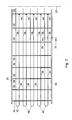
- Fig. 3 schematically shows in top plan view an example of a cutting frame as known from European Patent 1084609 , which is understood to be incorporated herein by reference
- Fig. 4 schematically shows a partial cross section along the line IV-IV of the cutting frame of Fig. 3.
- the cutting frame shown can be mounted in a conventional manner on a central rotatable shaft 5, whose centerline 27 is indicated schematically in Fig. 3.
- the cutting frame shown comprises two substantially parallel frame girders 30, 31, between which transverse knives 32 extend in transverse direction.
- the frame girders have a sharp cutting edge 33, which is situated at the top in Fig. 4, and a blunt, in this example rounded, lower edge.
- the transverse knives 32 have corresponding cutting edges 35 and blunt edges 36.
- the longitudinal knives have a sharp cutting edge 40 and a blunt edge 41, see Fig. 4 and Fig. 5.
- the longitudinal knives further have a length dimension, in which the cutting edge lies, a width dimension and a thickness.
- the transverse knives 32 and/or the longitudinal knives 38 can also have a cutting edge on both sides.
- the transverse knives are connected at the ends with the frame girders in a conventional manner by welds 37 (Fig. 4 and Fig. 5).
- the transverse knives are furthermore each provided with a series of openings, uniformly distributed along the length of the transverse knives. Each opening of a transverse knife is in line with corresponding openings of the other transverse knives and the openings are so designed that a longitudinal knife 38 can be slid into them.
- the longitudinal knives 38 are arranged loosely in the openings with a relatively large play. In this way, accumulation of curd material at the intersections of transverse and longitudinal knives is prevented and a good cleanability is obtained.
- the longitudinal knives can be assembled in a simple manner by sliding them into the openings of the transverse knives.
- the longitudinal knives can thereupon be jointly fixated, for instance in the manner known from European Patent 1084609 , with one or more transverse pins, or individually with a small number of welds, preferably one weld, as also described in European Patent 1084609 .
- U-shaped longitudinal knives are used, each consisting of two straight longitudinal knives 38, which are connected with each other by a bent part 42.
- one of the legs of such a U-shaped knife is welded to the transverse knife that is closest to the centerline 27 of the central shaft.
- the welds are indicated at 44 in Fig. 3.
- the openings in the transverse knives have various shapes, for instance a circular, oval, rectangular or diamond shape.
- the shape of the openings is such that the freedom of lateral movement of the longitudinal knives is limited adjacent the cutting edge and the blunt edge.
- the edges of an opening or at least the lower portion thereof may be provided with cut edges. If desired, also the upper edges, or all edges of the openings may be of sharp design so as to obtain a smallest possible contact surface with the longitudinal knives and a least possible chance of caking of dirt.
- FIG. 4 Examples of receiving openings for a longitudinal knife provided in a transverse knife are schematically shown in Figs. 4 and 5, each showing two adjacent openings 60 and 61, respectively, in which a U-shaped bent longitudinal knife 38 is received.
- This problem can be solved according to the invention without adversely affecting the construction of the cutting frame on points such as cleanability, flushability, simplicity, rapid assembly and finish.
- Fig. 6 schematically shows a transverse knife 32 for a cutting frame, in which are drawn, by way of example, a number of pairs of variants of passage openings according to the invention as well as one pair of known passage openings for U-shaped longitudinal knives 38.
- the respective longitudinal knives are represented in broken lines.
- the pairs of passage openings are indicated from left to right by 62, 63, 64, 65, and 66.
- the openings 62 correspond to the diamond-shaped openings 60 of the known transverse knife shown in Fig. 4 and are shown solely for the purpose of comparison.
- the other openings 63 to 66 deviate from these known openings in that they form supporting elements, which support a longitudinal knife extending through an opening at the wedge-shaped portion which forms the sharp cutting edge 40.
- the cutting edge proper is left clear by the supporting elements, as can be seen in Fig. 6 and also in Figs. 7 to 11.
- the supporting elements generally have the shape of, preferably rounded, projections in the form of, for instance, fingers, ears or the like, which form part of the edges of the openings in the transverse knives. Owing to the rounded shape, a small contact surface with the longitudinal knives is obtained.
- the openings 64 and 65 could be described as vase-shaped openings, the vase shape having a narrow neck zone that forms two rounded projections 70, 71.
- the sharp cutting edge of the knives has been formed by grinding the knives obliquely on one side, so that an oblique cutting face 50 is formed, which ends in the actual cutting edge 40.
- the projections 70, 71 abut against the longitudinal knives at the wedge-shaped edge 50 of the longitudinal knives, as drawn to a slightly larger scale in Figs. 7 and 8.
- the sharp cutting edge 40 proper extends just beyond the projections and lies clear.
- the longitudinal knives 38 are therefore fixated by the projections 70, 71 both in the horizontal and in the vertical direction ('horizontal' and 'vertical' are here related to the situation in Figs. 6, 7, and 8; in practice, a cutting frame can take up many positions with an associated orientation of the knives).
- the openings 64 in the orientation shown have an upper portion 64a, which is situated above the pair of projections 70, 71, and a lower portion 64b, which is below the projections.
- the sharp cutting edge 40 of a longitudinal knife 38 extends just beyond the projections into the upper portion 64a of the opening 64.
- the rest of the longitudinal knife, viewed in cross section, is situated in the lower portion 64b of the opening 64.
- the blunt lower edge 41 of a longitudinal knife 38 rests on the lower edge portion of the lower part 64b of the opening.
- the lower edge portion is shaped such that, in the plane of the paper, i.e., in a plane extending transversely to the longitudinal direction of the longitudinal knives, it forms an approximately cup-shaped or V-shaped portion 64c, in which the blunt lower edge 41 of the longitudinal knife is received.
- the blunt lower edge cannot, or hardly so, move laterally.
- the projections engaging the oblique cutting face 50 of the longitudinal knife limit both the possibility of lateral movement of the upper edge of the longitudinal knife and the possibility of vertical movement of the longitudinal knife. Accordingly, the cup-shaped or V-shaped portion 64c of the lower edge of the opening 64, together with the projections, substantially prevents torsion of a longitudinal knife.
- the openings 65 shown in Fig. 8 are slightly narrower and more pointed at the lower end than the openings 64 but for the rest have similar projections 70, 71 and have a similar fixation effect to the openings 64.
- the openings 63 and 66 shown in Figs. 10 and 11 differ from the openings 64 and 65 in that the openings 63 and 66, besides having the projections 70, 71 near the sharp edge 40 of a longitudinal knife 38, additionally have projections 72, 73 near the blunt lower edge 41 of a longitudinal knife situated in an opening, which projections 72, 73 support the lower part of the longitudinal knife laterally. In this way, while maintaining the good flushability, the possibility of lateral movement can be limited to a still larger extent.
- the openings 63 and 66 accordingly have an upper portion 63a and 66a, respectively, which is situated above the projections 70, 71, a middle portion 63b and 66b, respectively, in which the body of a longitudinal knife is located, and a lower portion 63c and 66c, respectively, situated below projections 72, 73, in which the lower edge 36 of a longitudinal knife is disposed, in the example of the openings 63 on a substantially straight lower edge of the lower portion 63c.
- the blunt lower edge 41 of a longitudinal knife rests on a locally upwardly extending section 66d of the lower edge of the lower portion 66c, so that a still more open construction with a very good flushability is formed.
- the lower portion 66c of the opening 66 in this example consists of two lobes 66c1 and 66c2, situated on opposite sides of the locally upwardly extending section 66d.
- FIG. 10 Another variant is shown at the openings 63 of Fig. 10, of which the upper portion 63a has been continued as far as the edge 35 of the transverse knife 32. This also promotes the openness of the construction.
- An upper portion of the passage opening for a longitudinal knife that is open towards the upper edge 35 of the transverse knife can, if desired, also be used in other variants of the passage openings.
- an upwardly extending section between two lobes, as shown in Fig. 11, can also be used in other exemplary embodiments with projections 72, 73 which support the lower part of a longitudinal knife.
- Fig. 9 a variant of the example of Fig. 8 is shown, where a vase-shaped opening 68 with an upper part 86a and a lower part 68b and locking projections 70, 71 are used, and where the lower part 68b is made of slightly more angular design than in Fig. 8.
- the cutting edge of the longitudinal knives in the examples shown has been formed by grinding the knives obliquely from one side. Accordingly, one projection (70) abuts against an oblique cutting face, while the other projection (71) abuts against a flat portion of the longitudinal knife.
- the projections should therefore be asymmetrical. If desired, however, it is also possible the grind the knives obliquely on both sides, so that a symmetrical cutting edge is formed, whereby both projections abut against an oblique edge and can be symmetrical. However, this requires an additional grinding operation.
- the passage openings in the transverse knives may be provided with corresponding pairs of locking projections for cooperation with the two wedge-shaped portions of such a longitudinal knife.
- the openings in the transverse knives can be cut out accurately, for instance using a laser.
- the rounded supporting elements may be sharpened at the contact surface with the longitudinal knives to further reduce the contact surface. The same may also be done at the location where a longitudinal knife rests on an opening edge.
- the invention is applicable in all variants of the cutting frames, transverse knives, and longitudinal knives, as well as fastening methods therefor as described in European Patent 1084609 , which is understood to be incorporated herein by reference.
- U-shaped longitudinal knives already described
- simple straight knives may be used, or U-shaped knives which are slid into the openings in the transverse knives from different ends of a cutting frame.
- transverse knives may be used that consist of two knives situated above each other with an interspace, the upper knife including an upper part of a receiving opening for a longitudinal knife and the lower knife including a lower part of the receiving opening.
- Such divided transverse knives are also understood to fall within the term transverse knives as used in this description and the claims.
- transverse knives may have receiving openings with supporting elements.
- a transverse knife may have an opening with supporting elements for one longitudinal knife and an opening without supporting elements for an adjacent longitudinal knife.
Landscapes
- Life Sciences & Earth Sciences (AREA)
- Animal Husbandry (AREA)
- Environmental Sciences (AREA)
- Knives (AREA)
- Crushing And Pulverization Processes (AREA)
- Food-Manufacturing Devices (AREA)
Abstract
Description
- This invention relates to a cutting frame for use in a curd vat, which cutting frame comprises substantially parallel frame girders, between which is situated a lattice formed from longitudinal knives and transverse knives, of which the transverse knives have been mounted on the frame girders by welding and have aligned openings, in which the longitudinal knives are received and wherein means are provided for substantially preventing displacement of the longitudinal knives in the longitudinal direction.
- The invention furthermore relates to a curd vat, also designated, for instance, as cheese vat, curd tank, curd container, cheese tank, etc., provided with one or more of such cutting frames. Such a curd vat may for instance be of a type as described in
United States Patent 4,108,058 or, for instance, of a type as marketed by Tetra Pak Tebel under the name of OST5. These known curd vats have a single rotatable shaft provided with a number of cutting frames mounted in staggered relation. The cutting frames according to the present invention, however, are also applicable in differently built-up curd vats, for instance curd vats with two shafts provided with cutting frames, as described, for instance, inUnited States Patent 4,989,504 . Further, the curd vats may be of the upright or lying type, whereby the shaft or shafts provided with cutting frames extends or extend substantially vertically and horizontally, respectively. - A cutting frame of the above-described kind and a curd vat provided with such cutting frames for cutting and stirring curd are known from
European Patent 1084609 . - All known apparatuses are arranged for stirring and cutting curd which has formed in the curd vat in that the vat has been filled with milk, to which starter and rennet have been added. To that end, depending on the type, one or more central shafts provided with cutting frames are driven for rotation, so that the cutting frames move through the curd formed. The cutting frames are usually so designed that the knives and the frame girders form a cutting edge along one edge and are blunt and rounded off along the other edge. Accordingly, rotation of the central shaft(s) in one direction yields substantially a cutting action, while rotation in the other direction yields substantially a stirring action.
- A problem which occurs in older known apparatuses but which has been solved by the construction described in
European Patent 1084609 is that the cutting frames in the older apparatuses comprise many welds, which must all be polished very well to prevent accumulation of contaminants and bacterial growth. The longitudinal knives can be arranged, for instance, with interspaces of the order of 4 to 5 cm and the transverse knives with interspaces of, for instance, 14.5 to 17.5 cm.
A cutting frame can, for instance, have a total width of the order of 50 cm and a length of, for instance, 150 cm. This means that a single cutting frame can comprise, for instance, about 100 rectangular lattice openings, each having four corners, where a longitudinal knife or a frame girder is welded to a transverse knife. Each of those welds not only needs to be provided, but also needs to be accurately polished to satisfy the requirements set by government regulations regarding cleanability. For the welding operation, however, little space is available within the lattice openings formed by the longitudinal and transverse elements of a cutting frame. As a consequence, the welding work and the polishing work are very time consuming and costly. - According to the solution to the outlined problem described in
European Patent 1084609 , the longitudinal knives are situated in the openings of the transverse knives with ample play, while displacement of the longitudinal knives in the longitudinal direction is prevented by special means. These special means can for instance comprise a locking pin arranged through openings in the transverse knives and the frame girders, or, for instance, a small number of welds, preferably a single weld, for securing a longitudinal knife to a small number of transverse knives, preferably one transverse knife. In this way, the necessary welding and polishing work is considerably reduced and simplified, while yet an effective cutting and stirring action and a good cleanability remain guaranteed. - In practice, it has been found that in the course of time the cutting edge of the longitudinal knives can exhibit wear adjacent the openings of the transverse knives, as well as in a small area before and behind the transverse knives. This is due to the fact that during a stirring movement of the cutting frame, the cutting edge of the longitudinal knives, since the latter are situated in the openings in the transverse knives with ample play, is pushed against the edge of the openings, whereby moreover some torsion may occur in the longitudinal knives, which presumably worsens the wear referred to.
- The object of the invention is to obviate the problem outlined. To this end, according to the invention, a cutting frame of the type described in the preamble is characterized in that at least a number of openings of at least a number of transverse knives is provided with supporting elements which substantially lock the longitudinal knives both in the lateral direction and in the width dimension, while the supporting elements leave the sharp cutting edge clear.
- In the following, the invention will be further described with reference to the accompanying drawing.
- Fig. 1 schematically shows in longitudinal cross section an example of a known curd vat in which curd can be stirred and cut;
- Fig. 2 schematically shows the apparatus of Fig. 1 in a cutaway view in the direction of the arrow II in Fig. 1;
- Fig. 3 schematically shows in top plan view an example of a cutting frame according to
European Patent 1084609 ; - Figs. 4 and 5 schematically show, in cross section along the line IV-IV in Fig. 3, examples of receiving openings provided in a transverse knife, in a cutting frame according to
European Patent 1084609 ; - Fig. 6 schematically shows in illustration a transverse knife with a pair of openings for a longitudinal knife according to
European Patent 1084609 and a number of examples of pairs of openings according to the invention; and - Figs. 7 to 11 show on a slightly larger scale examples of receiving openings for longitudinal knives according to the invention.
- In Figs. 1 and 2 a known cylindrical horizontally-disposed
curd vat 1 is shown, which is supported by a number oflegs 2. Theend walls curd vat 1 are of conical design in this example and through one of these end walls ashaft 5 extends centrally into the curd vat. In this example, a single central shaft is used. This shaft, which in this example is journaled in the opposite end wall, carries a set ofcutting frames 19, generally indicated by 6, for cutting and stirring curd in the curd vat.Reference numeral 7 designates a sealing element between theshaft 5 and thewall 3 through which theshaft 5 extends into the curd vat. - Outside the curd vat, the
shaft 5 in this example is connected by means of acoupling 8 to asecond shaft 9 of adrive motor 10. Themotor 10 is arranged for rotating the cutting frames around the centerline of thecurd vat 1 alternately in one direction and the other. - In this example, the
curd vat 1 in its upper part has amanhole 13 which is covered by amanhole cover 13a. In this example, further, another opening is provided in the upper part of thecurd vat 1, which opening is designated by 14 and is intended for the immersion of awhey sieve 15 in thecurd vat 1. Thewhey sieve 15 in this example is supported by abent pipe 16 which is rotatably connected with thecurd vat 1 at 17. Thecurd vat 1 has an inlet, not shown, and anoutlet 18 at its lowest part. A triangle P indicates a customary level of the curd in the curd vat. It is noted that the invention is also applicable to differently designed curd vats, such as for instance curd vats having more than one inlet and/or outlet or curd vats having more than one shaft provided with cutting frames, or curd vats having one or more vertical shafts, etc. Theshaft 5 carries a number ofcutting frames 19 which are situated side by side along theshaft 5, as appears from Fig. 1. In the embodiment shown, six cutting frames are used.. The number of sections depends on the size of the vat. The cutting frames in this example are connected to the shaft so as to form angles with each other, as can be seen in Fig. 2. In the embodiment shown, the cutting frames are placed along theshaft 5 so as to extend outwardly from the shaft in a helical configuration. - Each of the cutting frames may further be fitted on the
shaft 5 at an angle, as illustrated in Fig. 1 by abroken line 20 indicating the cutting frame which is located farthest to the left and is hidden by theshaft 5. - Fig. 3 schematically shows in top plan view an example of a cutting frame as known from
European Patent 1084609 , which is understood to be incorporated herein by reference, and Fig. 4 schematically shows a partial cross section along the line IV-IV of the cutting frame of Fig. 3. The cutting frame shown can be mounted in a conventional manner on a centralrotatable shaft 5, whosecenterline 27 is indicated schematically in Fig. 3. The cutting frame shown comprises two substantiallyparallel frame girders 30, 31, between whichtransverse knives 32 extend in transverse direction. The frame girders have asharp cutting edge 33, which is situated at the top in Fig. 4, and a blunt, in this example rounded, lower edge. Also, thetransverse knives 32 havecorresponding cutting edges 35 andblunt edges 36. Similarly, the longitudinal knives have asharp cutting edge 40 and ablunt edge 41, see Fig. 4 and Fig. 5. The longitudinal knives further have a length dimension, in which the cutting edge lies, a width dimension and a thickness. If desired, thetransverse knives 32 and/or thelongitudinal knives 38 can also have a cutting edge on both sides. The transverse knives are connected at the ends with the frame girders in a conventional manner by welds 37 (Fig. 4 and Fig. 5). The transverse knives are furthermore each provided with a series of openings, uniformly distributed along the length of the transverse knives. Each opening of a transverse knife is in line with corresponding openings of the other transverse knives and the openings are so designed that alongitudinal knife 38 can be slid into them. Thelongitudinal knives 38 are arranged loosely in the openings with a relatively large play. In this way, accumulation of curd material at the intersections of transverse and longitudinal knives is prevented and a good cleanability is obtained. The longitudinal knives can be assembled in a simple manner by sliding them into the openings of the transverse knives. The longitudinal knives can thereupon be jointly fixated, for instance in the manner known fromEuropean Patent 1084609 , with one or more transverse pins, or individually with a small number of welds, preferably one weld, as also described inEuropean Patent 1084609 . In the example shown, U-shaped longitudinal knives are used, each consisting of two straightlongitudinal knives 38, which are connected with each other by abent part 42. In the embodiment of Fig. 3, one of the legs of such a U-shaped knife is welded to the transverse knife that is closest to thecenterline 27 of the central shaft. The welds are indicated at 44 in Fig. 3. - The openings in the transverse knives, according to
European Patent 1084609 , have various shapes, for instance a circular, oval, rectangular or diamond shape. In general, the shape of the openings is such that the freedom of lateral movement of the longitudinal knives is limited adjacent the cutting edge and the blunt edge. The edges of an opening or at least the lower portion thereof may be provided with cut edges. If desired, also the upper edges, or all edges of the openings may be of sharp design so as to obtain a smallest possible contact surface with the longitudinal knives and a least possible chance of caking of dirt. - Examples of receiving openings for a longitudinal knife provided in a transverse knife are schematically shown in Figs. 4 and 5, each showing two
adjacent openings longitudinal knife 38 is received. - As already noted, it has been found in practice that in the course of time the
cutting edge 40 of the longitudinal knives of a cutting frame as described inEuropean Patent 1084609 exhibits wear in thearea 43 at and near the openings in the transverse knives, as indicated in Fig. 4 and Fig. 5. - This problem can be solved according to the invention without adversely affecting the construction of the cutting frame on points such as cleanability, flushability, simplicity, rapid assembly and finish.
- Fig. 6 schematically shows a
transverse knife 32 for a cutting frame, in which are drawn, by way of example, a number of pairs of variants of passage openings according to the invention as well as one pair of known passage openings for U-shapedlongitudinal knives 38. In Fig. 6, the respective longitudinal knives are represented in broken lines. The pairs of passage openings are indicated from left to right by 62, 63, 64, 65, and 66. Theopenings 62 correspond to the diamond-shapedopenings 60 of the known transverse knife shown in Fig. 4 and are shown solely for the purpose of comparison. - The
other openings 63 to 66 deviate from these known openings in that they form supporting elements, which support a longitudinal knife extending through an opening at the wedge-shaped portion which forms thesharp cutting edge 40. The cutting edge proper, however, is left clear by the supporting elements, as can be seen in Fig. 6 and also in Figs. 7 to 11. - The supporting elements generally have the shape of, preferably rounded, projections in the form of, for instance, fingers, ears or the like, which form part of the edges of the openings in the transverse knives. Owing to the rounded shape, a small contact surface with the longitudinal knives is obtained. The
openings rounded projections - The sharp cutting edge of the knives has been formed by grinding the knives obliquely on one side, so that an
oblique cutting face 50 is formed, which ends in theactual cutting edge 40. - The
projections edge 50 of the longitudinal knives, as drawn to a slightly larger scale in Figs. 7 and 8. Thesharp cutting edge 40 proper, however, extends just beyond the projections and lies clear. Thelongitudinal knives 38 are therefore fixated by theprojections - The
openings 64 in the orientation shown have anupper portion 64a, which is situated above the pair ofprojections lower portion 64b, which is below the projections. Thesharp cutting edge 40 of alongitudinal knife 38 extends just beyond the projections into theupper portion 64a of theopening 64. The rest of the longitudinal knife, viewed in cross section, is situated in thelower portion 64b of theopening 64. The bluntlower edge 41 of alongitudinal knife 38 rests on the lower edge portion of thelower part 64b of the opening. In the case of theopenings 64, the lower edge portion is shaped such that, in the plane of the paper, i.e., in a plane extending transversely to the longitudinal direction of the longitudinal knives, it forms an approximately cup-shaped or V-shapedportion 64c, in which the bluntlower edge 41 of the longitudinal knife is received. As a result, the blunt lower edge cannot, or hardly so, move laterally. The projections engaging theoblique cutting face 50 of the longitudinal knife limit both the possibility of lateral movement of the upper edge of the longitudinal knife and the possibility of vertical movement of the longitudinal knife. Accordingly, the cup-shaped or V-shapedportion 64c of the lower edge of theopening 64, together with the projections, substantially prevents torsion of a longitudinal knife. - The
openings 65 shown in Fig. 8 are slightly narrower and more pointed at the lower end than theopenings 64 but for the rest havesimilar projections openings 64. - The
openings openings openings projections sharp edge 40 of alongitudinal knife 38, additionally haveprojections lower edge 41 of a longitudinal knife situated in an opening, whichprojections - The
openings upper portion projections middle portion lower portion projections lower edge 36 of a longitudinal knife is disposed, in the example of theopenings 63 on a substantially straight lower edge of thelower portion 63c. - In the example of the
openings 66 of Fig. 11, the bluntlower edge 41 of a longitudinal knife rests on a locally upwardly extendingsection 66d of the lower edge of thelower portion 66c, so that a still more open construction with a very good flushability is formed. Thelower portion 66c of theopening 66 in this example consists of two lobes 66c1 and 66c2, situated on opposite sides of the locally upwardly extendingsection 66d. - Another variant is shown at the
openings 63 of Fig. 10, of which theupper portion 63a has been continued as far as theedge 35 of thetransverse knife 32. This also promotes the openness of the construction. An upper portion of the passage opening for a longitudinal knife that is open towards theupper edge 35 of the transverse knife can, if desired, also be used in other variants of the passage openings. Likewise, an upwardly extending section between two lobes, as shown in Fig. 11, can also be used in other exemplary embodiments withprojections - It is noted that many variants of the receiving openings for the longitudinal knives in the transverse knives are possible. For the sake of completeness, in Fig. 9 a variant of the example of Fig. 8 is shown, where a vase-shaped
opening 68 with an upper part 86a and alower part 68b and lockingprojections lower part 68b is made of slightly more angular design than in Fig. 8. - Furthermore, it is noted that the cutting edge of the longitudinal knives in the examples shown has been formed by grinding the knives obliquely from one side. Accordingly, one projection (70) abuts against an oblique cutting face, while the other projection (71) abuts against a flat portion of the longitudinal knife. The projections should therefore be asymmetrical. If desired, however, it is also possible the grind the knives obliquely on both sides, so that a symmetrical cutting edge is formed, whereby both projections abut against an oblique edge and can be symmetrical. However, this requires an additional grinding operation.
- If a longitudinal knife is used of which both longitudinal edges have been sharpened, the passage openings in the transverse knives may be provided with corresponding pairs of locking projections for cooperation with the two wedge-shaped portions of such a longitudinal knife.
- The openings in the transverse knives can be cut out accurately, for instance using a laser. If desired, the rounded supporting elements may be sharpened at the contact surface with the longitudinal knives to further reduce the contact surface. The same may also be done at the location where a longitudinal knife rests on an opening edge.
- Further, it is noted that the invention is applicable in all variants of the cutting frames, transverse knives, and longitudinal knives, as well as fastening methods therefor as described in
European Patent 1084609 , which is understood to be incorporated herein by reference. For instance, besides the U-shaped longitudinal knives already described, also simple straight knives may be used, or U-shaped knives which are slid into the openings in the transverse knives from different ends of a cutting frame. Also, transverse knives may be used that consist of two knives situated above each other with an interspace, the upper knife including an upper part of a receiving opening for a longitudinal knife and the lower knife including a lower part of the receiving opening. Such divided transverse knives are also understood to fall within the term transverse knives as used in this description and the claims. - Furthermore, it is possible that not all transverse knives have receiving openings with supporting elements. For instance, a transverse knife may have an opening with supporting elements for one longitudinal knife and an opening without supporting elements for an adjacent longitudinal knife.
- It is also possible to use supporting elements in other configurations, where some projections are not situated straight opposite each other.
- All of these and similar variants and modifications will be readily apparent to those skilled in the art and are understood to fall within the framework of the invention.
Claims (14)
- A cutting frame for use in a curd vat, which cutting frame comprises substantially parallel frame girders, between which is situated a lattice formed from longitudinal knives and transverse knives, of which the transverse knives are mounted on the frame girders by welding and have aligned openings, in which the longitudinal knives are received, wherein the longitudinal knives are strip-shaped knives having a length dimension and a width dimension and having at least one sharp cutting edge extending in the length dimension, which cutting edge is formed by at least one obliquely ground cutting face, wherein the width of the longitudinal knives is smaller than the corresponding dimension of the openings of the transverse knives, and wherein means are provided for substantially preventing displacement of the longitudinal knives in the length dimension, characterized in that at least a number of openings of at least a number of transverse knives is provided with supporting elements which substantially lock the longitudinal knives both in lateral direction and in the width dimension of the longitudinal knives, while the supporting elements leave the sharp cutting edge clear.
- A cutting frame according to claim 1, wherein the supporting elements comprise a number of projections extending from the edges of said number of openings of said number of transverse knives and lying in the plane of the transverse knives, wherein at least two projections, near the cutting edge, abut on opposite sides against a longitudinal knife, while at least one of the projections abuts against the at least one obliquely ground cutting face.
- A cutting frame according to claim 2, wherein the projections are rounded off at least at the location of the contact with the longitudinal knives.
- A cutting frame according to claim 2 or 3, wherein the projections have been sharpened at least at the location of the contact with the longitudinal knives.
- A cutting frame according to any one of claims 2 to 4, wherein the projections comprise at least one pair of projections abutting on opposite sides against a longitudinal knife.
- A cutting frame according to claim 5, wherein the projections of at least one pair are situated substantially straight opposite each other.
- A cutting frame according to any one of claims 2 to 6, wherein the projections comprise at least two projections abutting on opposite sides against a longitudinal knife remote from the cutting edge.
- A cutting frame according to claim 7, wherein the projections abutting against a longitudinal knife remote from the cutting edge comprise at least two projections abutting on opposite sides against a longitudinal knife near a knife edge situated opposite said cutting edge.
- A cutting frame according to any one of the preceding claims, wherein said number of openings comprises at least a number of openings with an upper portion that extends from supporting elements situated near the cutting edge of the longitudinal knives as far as a nearby cutting edge of the transverse knife.
- A cutting frame according to any one of claims 7 to 9, wherein a longitudinal knife is supported by way of the knife edge situated opposite the cutting edge on a section of the edge of the opening in the transverse knife that extends substantially transversely to that knife edge.
- A cutting frame according to any one of claims 7 to 9, wherein the longitudinal knife is supported by way of the knife edge situated opposite the cutting edge on a section of the edge of the opening in the transverse knife that extends upwards between two lobes of the opening.
- A cutting frame according to any one of claims 1 to 11, wherein the supporting elements form an integral part of the transverse knives in that the supporting elements have been cut from the transverse knives simultaneously with the openings.
- A transverse knife for a cutting frame according to any one of claims 1 to 12, provided with at least one opening designed with supporting elements for a longitudinal knife.
- A curd vat provided with at least one cutting frame according to any one of the preceding claims 1 to 12.
Priority Applications (1)
| Application Number | Priority Date | Filing Date | Title |
|---|---|---|---|
| PL07109381T PL1862065T3 (en) | 2006-06-02 | 2007-06-01 | Cutting frame for use in a curd vat |
Applications Claiming Priority (1)
| Application Number | Priority Date | Filing Date | Title |
|---|---|---|---|
| NL1031949A NL1031949C2 (en) | 2006-06-02 | 2006-06-02 | Cutting frame for use in a curd vat. |
Publications (2)
| Publication Number | Publication Date |
|---|---|
| EP1862065A1 true EP1862065A1 (en) | 2007-12-05 |
| EP1862065B1 EP1862065B1 (en) | 2012-05-30 |
Family
ID=37698229
Family Applications (1)
| Application Number | Title | Priority Date | Filing Date |
|---|---|---|---|
| EP07109381A Not-in-force EP1862065B1 (en) | 2006-06-02 | 2007-06-01 | Cutting frame for use in a curd vat |
Country Status (7)
| Country | Link |
|---|---|
| US (1) | US7823504B2 (en) |
| EP (1) | EP1862065B1 (en) |
| AU (1) | AU2007202535B2 (en) |
| DK (1) | DK1862065T3 (en) |
| NL (1) | NL1031949C2 (en) |
| NZ (1) | NZ555577A (en) |
| PL (1) | PL1862065T3 (en) |
Cited By (1)
| Publication number | Priority date | Publication date | Assignee | Title |
|---|---|---|---|---|
| DK177919B1 (en) * | 2009-04-15 | 2015-01-05 | Tetra Laval Holdings & Finance | A cutting device having exchangeable knives |
Families Citing this family (2)
| Publication number | Priority date | Publication date | Assignee | Title |
|---|---|---|---|---|
| US9114437B2 (en) | 2010-04-19 | 2015-08-25 | Cheese & Whey Systems, Inc. | Manway for food processing equipment |
| US9073019B2 (en) | 2010-04-19 | 2015-07-07 | Cheese & Whey Systems, Inc. | Blade arrangement for a food processing vat |
Citations (4)
| Publication number | Priority date | Publication date | Assignee | Title |
|---|---|---|---|---|
| US4108058A (en) | 1975-04-18 | 1978-08-22 | Alfa-Laval Ab | Cheese-making apparatus |
| CH666384A5 (en) * | 1985-05-17 | 1988-07-29 | Hoegger Alpina Ag | Revolving cutter rotated in vessel contg. curds in cheese prodn. - has rectangular frame contg. at least one set of sharp-edged, pref. steel, strips as cutting blades |
| US4989504A (en) | 1988-11-09 | 1991-02-05 | Sherping Systems, Inc. | Food processing vat |
| EP1084609A1 (en) | 1999-09-17 | 2001-03-21 | Tetra Laval Holdings & Finance S.A. | Apparatus for cutting and stirring curd |
Family Cites Families (1)
| Publication number | Priority date | Publication date | Assignee | Title |
|---|---|---|---|---|
| NL1015016C2 (en) * | 2000-04-25 | 2001-10-26 | Tetra Laval Holdings & Finance | Device for cutting and stirring curd. |
-
2006
- 2006-06-02 NL NL1031949A patent/NL1031949C2/en not_active IP Right Cessation
-
2007
- 2007-06-01 EP EP07109381A patent/EP1862065B1/en not_active Not-in-force
- 2007-06-01 AU AU2007202535A patent/AU2007202535B2/en active Active
- 2007-06-01 PL PL07109381T patent/PL1862065T3/en unknown
- 2007-06-01 US US11/756,943 patent/US7823504B2/en active Active
- 2007-06-01 DK DK07109381.9T patent/DK1862065T3/en active
- 2007-06-01 NZ NZ555577A patent/NZ555577A/en not_active IP Right Cessation
Patent Citations (4)
| Publication number | Priority date | Publication date | Assignee | Title |
|---|---|---|---|---|
| US4108058A (en) | 1975-04-18 | 1978-08-22 | Alfa-Laval Ab | Cheese-making apparatus |
| CH666384A5 (en) * | 1985-05-17 | 1988-07-29 | Hoegger Alpina Ag | Revolving cutter rotated in vessel contg. curds in cheese prodn. - has rectangular frame contg. at least one set of sharp-edged, pref. steel, strips as cutting blades |
| US4989504A (en) | 1988-11-09 | 1991-02-05 | Sherping Systems, Inc. | Food processing vat |
| EP1084609A1 (en) | 1999-09-17 | 2001-03-21 | Tetra Laval Holdings & Finance S.A. | Apparatus for cutting and stirring curd |
Cited By (1)
| Publication number | Priority date | Publication date | Assignee | Title |
|---|---|---|---|---|
| DK177919B1 (en) * | 2009-04-15 | 2015-01-05 | Tetra Laval Holdings & Finance | A cutting device having exchangeable knives |
Also Published As
| Publication number | Publication date |
|---|---|
| NL1031949C2 (en) | 2007-12-04 |
| AU2007202535A1 (en) | 2007-12-20 |
| US7823504B2 (en) | 2010-11-02 |
| PL1862065T3 (en) | 2012-10-31 |
| US20070277680A1 (en) | 2007-12-06 |
| DK1862065T3 (en) | 2012-08-20 |
| AU2007202535B2 (en) | 2009-11-26 |
| EP1862065B1 (en) | 2012-05-30 |
| NZ555577A (en) | 2007-11-30 |
Similar Documents
| Publication | Publication Date | Title |
|---|---|---|
| EP1862065B1 (en) | Cutting frame for use in a curd vat | |
| DE2513675C3 (en) | Cutter suction dredger | |
| EP1084609B1 (en) | Apparatus for cutting and stirring curd | |
| US6418836B2 (en) | Apparatus for cutting and stirring curd | |
| US7841271B2 (en) | Cheese vat for preparing soft fresh cheese, and cutting frame for a cheese vat | |
| EP2241172A1 (en) | Lawn-mower | |
| EP2418934B1 (en) | A cutting frame having exchangeable knives, cutting device and curd vat with such a cutting frame | |
| US5052290A (en) | Cheese-making tank | |
| US4767218A (en) | Mixing paddle assembly | |
| CN214257882U (en) | Egg beater with yolk and egg white separating device | |
| KR102220136B1 (en) | sludge collector with separable driving unit | |
| CN214854099U (en) | Egg stirring machine | |
| JP3451086B1 (en) | Tilling claw member and tillage claw mounting device | |
| EP0449760A2 (en) | A tank with a double stirring system, primarily a curdling tank | |
| EP4014724B1 (en) | Support structure for whey draining belt | |
| KR100507775B1 (en) | rotating cutter in device for eliminating of sawdust | |
| DE102005050187A1 (en) | Scheibenmähwerk | |
| DE29809596U1 (en) | mowing machine |
Legal Events
| Date | Code | Title | Description |
|---|---|---|---|
| PUAI | Public reference made under article 153(3) epc to a published international application that has entered the european phase |
Free format text: ORIGINAL CODE: 0009012 |
|
| AK | Designated contracting states |
Kind code of ref document: A1 Designated state(s): AT BE BG CH CY CZ DE DK EE ES FI FR GB GR HU IE IS IT LI LT LU LV MC MT NL PL PT RO SE SI SK TR |
|
| AX | Request for extension of the european patent |
Extension state: AL BA HR MK YU |
|
| 17P | Request for examination filed |
Effective date: 20080129 |
|
| AKX | Designation fees paid |
Designated state(s): DE DK GB NL PL SE |
|
| GRAP | Despatch of communication of intention to grant a patent |
Free format text: ORIGINAL CODE: EPIDOSNIGR1 |
|
| GRAS | Grant fee paid |
Free format text: ORIGINAL CODE: EPIDOSNIGR3 |
|
| RAP1 | Party data changed (applicant data changed or rights of an application transferred) |
Owner name: TETRA LAVAL HOLDINGS & FINANCE S.A. |
|
| GRAA | (expected) grant |
Free format text: ORIGINAL CODE: 0009210 |
|
| AK | Designated contracting states |
Kind code of ref document: B1 Designated state(s): DE DK GB NL PL SE |
|
| REG | Reference to a national code |
Ref country code: GB Ref legal event code: FG4D |
|
| REG | Reference to a national code |
Ref country code: DE Ref legal event code: R096 Ref document number: 602007022947 Country of ref document: DE Effective date: 20120802 |
|
| REG | Reference to a national code |
Ref country code: DK Ref legal event code: T3 |
|
| REG | Reference to a national code |
Ref country code: NL Ref legal event code: T3 |
|
| REG | Reference to a national code |
Ref country code: SE Ref legal event code: TRGR |
|
| REG | Reference to a national code |
Ref country code: PL Ref legal event code: T3 |
|
| PLBE | No opposition filed within time limit |
Free format text: ORIGINAL CODE: 0009261 |
|
| STAA | Information on the status of an ep patent application or granted ep patent |
Free format text: STATUS: NO OPPOSITION FILED WITHIN TIME LIMIT |
|
| 26N | No opposition filed |
Effective date: 20130301 |
|
| REG | Reference to a national code |
Ref country code: DE Ref legal event code: R097 Ref document number: 602007022947 Country of ref document: DE Effective date: 20130301 |
|
| PGFP | Annual fee paid to national office [announced via postgrant information from national office to epo] |
Ref country code: PL Payment date: 20180322 Year of fee payment: 12 |
|
| PGFP | Annual fee paid to national office [announced via postgrant information from national office to epo] |
Ref country code: DK Payment date: 20180612 Year of fee payment: 12 |
|
| PGFP | Annual fee paid to national office [announced via postgrant information from national office to epo] |
Ref country code: SE Payment date: 20180612 Year of fee payment: 12 |
|
| PGFP | Annual fee paid to national office [announced via postgrant information from national office to epo] |
Ref country code: GB Payment date: 20180403 Year of fee payment: 12 |
|
| REG | Reference to a national code |
Ref country code: DK Ref legal event code: EBP Effective date: 20190630 |
|
| REG | Reference to a national code |
Ref country code: SE Ref legal event code: EUG |
|
| PG25 | Lapsed in a contracting state [announced via postgrant information from national office to epo] |
Ref country code: SE Free format text: LAPSE BECAUSE OF NON-PAYMENT OF DUE FEES Effective date: 20190602 |
|
| GBPC | Gb: european patent ceased through non-payment of renewal fee |
Effective date: 20190601 |
|
| PG25 | Lapsed in a contracting state [announced via postgrant information from national office to epo] |
Ref country code: GB Free format text: LAPSE BECAUSE OF NON-PAYMENT OF DUE FEES Effective date: 20190601 |
|
| PG25 | Lapsed in a contracting state [announced via postgrant information from national office to epo] |
Ref country code: DK Free format text: LAPSE BECAUSE OF NON-PAYMENT OF DUE FEES Effective date: 20190630 |
|
| PG25 | Lapsed in a contracting state [announced via postgrant information from national office to epo] |
Ref country code: PL Free format text: LAPSE BECAUSE OF NON-PAYMENT OF DUE FEES Effective date: 20190601 |
|
| P01 | Opt-out of the competence of the unified patent court (upc) registered |
Effective date: 20230426 |
|
| PGFP | Annual fee paid to national office [announced via postgrant information from national office to epo] |
Ref country code: DE Payment date: 20240627 Year of fee payment: 18 |
|
| PGFP | Annual fee paid to national office [announced via postgrant information from national office to epo] |
Ref country code: NL Payment date: 20240625 Year of fee payment: 18 |
|
| REG | Reference to a national code |
Ref country code: DE Ref legal event code: R119 Ref document number: 602007022947 Country of ref document: DE |
|
| REG | Reference to a national code |
Ref country code: NL Ref legal event code: MM Effective date: 20250701 |
|
| PG25 | Lapsed in a contracting state [announced via postgrant information from national office to epo] |
Ref country code: NL Free format text: LAPSE BECAUSE OF NON-PAYMENT OF DUE FEES Effective date: 20250701 |
|
| PG25 | Lapsed in a contracting state [announced via postgrant information from national office to epo] |
Ref country code: DE Free format text: LAPSE BECAUSE OF NON-PAYMENT OF DUE FEES Effective date: 20260101 |