EP1861844B1 - Method and/or apparatus to improve the visual perception of an image displayed on a screen - Google Patents
Method and/or apparatus to improve the visual perception of an image displayed on a screen Download PDFInfo
- Publication number
- EP1861844B1 EP1861844B1 EP06744418A EP06744418A EP1861844B1 EP 1861844 B1 EP1861844 B1 EP 1861844B1 EP 06744418 A EP06744418 A EP 06744418A EP 06744418 A EP06744418 A EP 06744418A EP 1861844 B1 EP1861844 B1 EP 1861844B1
- Authority
- EP
- European Patent Office
- Prior art keywords
- lighting lamp
- mean
- effective
- value
- contrast
- Prior art date
- Legal status (The legal status is an assumption and is not a legal conclusion. Google has not performed a legal analysis and makes no representation as to the accuracy of the status listed.)
- Not-in-force
Links
Images

Classifications
-
- G—PHYSICS
- G02—OPTICS
- G02F—OPTICAL DEVICES OR ARRANGEMENTS FOR THE CONTROL OF LIGHT BY MODIFICATION OF THE OPTICAL PROPERTIES OF THE MEDIA OF THE ELEMENTS INVOLVED THEREIN; NON-LINEAR OPTICS; FREQUENCY-CHANGING OF LIGHT; OPTICAL LOGIC ELEMENTS; OPTICAL ANALOGUE/DIGITAL CONVERTERS
- G02F1/00—Devices or arrangements for the control of the intensity, colour, phase, polarisation or direction of light arriving from an independent light source, e.g. switching, gating or modulating; Non-linear optics
- G02F1/01—Devices or arrangements for the control of the intensity, colour, phase, polarisation or direction of light arriving from an independent light source, e.g. switching, gating or modulating; Non-linear optics for the control of the intensity, phase, polarisation or colour
- G02F1/13—Devices or arrangements for the control of the intensity, colour, phase, polarisation or direction of light arriving from an independent light source, e.g. switching, gating or modulating; Non-linear optics for the control of the intensity, phase, polarisation or colour based on liquid crystals, e.g. single liquid crystal display cells
- G02F1/133—Constructional arrangements; Operation of liquid crystal cells; Circuit arrangements
-
- G—PHYSICS
- G09—EDUCATION; CRYPTOGRAPHY; DISPLAY; ADVERTISING; SEALS
- G09G—ARRANGEMENTS OR CIRCUITS FOR CONTROL OF INDICATING DEVICES USING STATIC MEANS TO PRESENT VARIABLE INFORMATION
- G09G3/00—Control arrangements or circuits, of interest only in connection with visual indicators other than cathode-ray tubes
- G09G3/20—Control arrangements or circuits, of interest only in connection with visual indicators other than cathode-ray tubes for presentation of an assembly of a number of characters, e.g. a page, by composing the assembly by combination of individual elements arranged in a matrix no fixed position being assigned to or needed to be assigned to the individual characters or partial characters
- G09G3/34—Control arrangements or circuits, of interest only in connection with visual indicators other than cathode-ray tubes for presentation of an assembly of a number of characters, e.g. a page, by composing the assembly by combination of individual elements arranged in a matrix no fixed position being assigned to or needed to be assigned to the individual characters or partial characters by control of light from an independent source
- G09G3/3406—Control of illumination source
-
- H—ELECTRICITY
- H04—ELECTRIC COMMUNICATION TECHNIQUE
- H04N—PICTORIAL COMMUNICATION, e.g. TELEVISION
- H04N5/00—Details of television systems
- H04N5/44—Receiver circuitry for the reception of television signals according to analogue transmission standards
- H04N5/57—Control of contrast or brightness
-
- G—PHYSICS
- G09—EDUCATION; CRYPTOGRAPHY; DISPLAY; ADVERTISING; SEALS
- G09G—ARRANGEMENTS OR CIRCUITS FOR CONTROL OF INDICATING DEVICES USING STATIC MEANS TO PRESENT VARIABLE INFORMATION
- G09G2320/00—Control of display operating conditions
- G09G2320/06—Adjustment of display parameters
- G09G2320/0626—Adjustment of display parameters for control of overall brightness
- G09G2320/0646—Modulation of illumination source brightness and image signal correlated to each other
-
- G—PHYSICS
- G09—EDUCATION; CRYPTOGRAPHY; DISPLAY; ADVERTISING; SEALS
- G09G—ARRANGEMENTS OR CIRCUITS FOR CONTROL OF INDICATING DEVICES USING STATIC MEANS TO PRESENT VARIABLE INFORMATION
- G09G2320/00—Control of display operating conditions
- G09G2320/06—Adjustment of display parameters
- G09G2320/066—Adjustment of display parameters for control of contrast
-
- G—PHYSICS
- G09—EDUCATION; CRYPTOGRAPHY; DISPLAY; ADVERTISING; SEALS
- G09G—ARRANGEMENTS OR CIRCUITS FOR CONTROL OF INDICATING DEVICES USING STATIC MEANS TO PRESENT VARIABLE INFORMATION
- G09G2360/00—Aspects of the architecture of display systems
- G09G2360/16—Calculation or use of calculated indices related to luminance levels in display data
Definitions
- the present invention relates to a method and/or apparatus for improving the visual perception of images displayed on a screen, in particular on a liquid crystal screen (LCD, Liquid Crystal Display).
- LCD liquid crystal screen
- the present invention relates to a method and/or apparatus adapted to improve the visual perception of dark images, i.e. low-brightness images, displayed on an LCD screen.
- LCD screens are illuminated by using a rear-lighting lamp, which is a source of white light.
- the PCT International Patent Application No. WO 2004/049293 describes a method to improve the perception of images displayed on a screen by measuring the value of a number of parameters, among which the brightness of a frame and that of the single pixels composing it.
- an adjusting circuit In relation with the values of the measured parameters, an adjusting circuit generates a global brightness control signal and a local brightness control signal.
- the global adjustment is carried out by means of an optical diaphragm.
- the US Patent Application No. US 2001/0033260 describes a liquid crystal display (LCD) device comprising a liquid crystal panel, a rear-lighting lamp for illuminating the liquid crystal panel, a section for detecting the luminance characteristics of a frame, and a section for controlling the rear-lighting lamp in order to adjust the light produced by the rear-lighting lamp in accordance with the luminance characteristics of the frame.
- LCD liquid crystal display
- Document EP 1111578 describes an image display apparatus displaying a video signal to be inputted on a passive light modulation part including a light source as an image, the apparatus comprising: an amplitude adjustment part dynamically adjusting an amplitude of the video signal to become a predetermined amplitude value; and a light source brightness adjustment part adjusting brightness of said light source according to amplitude adjustment by the amplitude adjustment part so that the image displayed on the passive light modulation part based on the video signal after amplitude adjustment does not vary visually from a predetermined level which is an average brightness level of each frame in the video signal to be inputted.
- the object of the present invention is to provide a method and/or apparatus to improve the visual perception of the images displayed on a screen, said method and/or apparatus being effective and operating according to the scenic contents of such images.
- a method and/or an apparatus which exploits the rear-lighting lamp power adjustment and the contrast adjustment in order to obtain higher contrast ratios whenever it is not necessary to use the maximum available lamp power.
- the method and/or apparatus according to the invention therefore operates in the darkest scenes, i.e. when the image histogram is unbalanced toward the lowest luminance levels. In such a case, in fact, it is possible to reduce the power of the rear-lighting lamp power, thereby lowering the level of black, and then to recover the intermediate luminance levels by acting on the signal, in particular by increasing the contrast.
- the method and/or apparatus operates in dark scenes, the levels of white which might be saturated as a consequence of the contrast increase will not produce relevant counterfeits, and the images will be advantageously perceived by the observer as more contrasted.
- the method and/or apparatus according to the invention provides a gradual variation of the brightness of the image perceived by the observer, so that such brightness variation will not be perceived by the observer as a disturbing flickering.
- the method and/or apparatus according to the invention takes into consideration the brightness variations occurring during the scene changes of the images, e.g. when there is a transition from a sunny landscape to a poorly lit indoor environment or a night scene.
- the following will describe a liquid crystal panel implementing the method according to the present invention and a liquid crystal screen to which said panel is fastened.
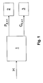
- Fig. 1 illustrates a basic diagram of the architecture implementing the method and/or apparatus according to the invention, wherein an image frame H is received by an analysis and adjusting block 1, which analyses a plurality of image frames H and outputs a signal P E,i+1 adapted to adjust the power of the rear-lighting lamp of a liquid crystal (LCD) panel, not shown, and a signal C E,i+1 adapted to adjust the contrast of the image displayed on a screen, also not shown, to which said panel is fastened.
- an analysis and adjusting block 1 which analyses a plurality of image frames H and outputs a signal P E,i+1 adapted to adjust the power of the rear-lighting lamp of a liquid crystal (LCD) panel, not shown, and a signal C E,i+1 adapted to adjust the contrast of the image displayed on a screen, also not shown, to which said panel is fastened.
- LCD liquid crystal
- the signals P E,i+1 and C E,i+1 are sent to a power adjusting circuit 2 of a rear-lighting lamp and to an image contrast control circuit 3, respectively.
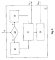
- Fig. 2 illustrates in detail the analysis and adjusting block 1, which comprises: a block 4 which calculates the spatially averaged luminance of a frame H; a sliding register 5 made up of 2 N cells 5a ... 5n, preferably of 8 bits, wherein N is an integer; a module for calculating the absolute value of the difference between the mean luminance of the current frame y i and the average of the mean luminances of the previous frames, consisting of a first adder 7, a register 9, a divisor 11, a second adder 13 and a module 15 which calculates the absolute value; and, finally, a control block 17 operation of which will be detailed later.
- the analysis and adjusting block 1 may be either implemented in a dedicated microprocessor or provided by advantageously programming a dedicated microprocessor of the LCD panel.
- the analysis and adjusting block 1 operates as follows.
- the mean luminance y i of the frame H is first calculated in the block 4. The value y i is then entered in the sliding register 5.
- the value d i represents the distance between the mean luminance y i of the current frame and the average of the mean luminances of the previous frames.
- the value d i is therefore an indicator of the proximity between the luminance of the current frame i and that of the 2 N previous frames.
- the analysis and adjusting block 1 acts as a detector of the differential luminance between a frame and the previous ones.
- the control block 17 can generate a command signal RESET which sets to y i all the cells 5a ... 5n of the sliding register 5. The usefulness of this setting will become apparent from the following description.
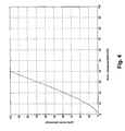
- Figs. 3 and 4 respectively illustrate in detail a block diagram describing the operation of the control block 17 and a graph representing a function the values of which are used within the control block 17.
- the control block 17 receives the signal d i from the output of the block 15 and outputs a power adjusting signal P E,i+1 of a rear-lighting lamp and a contrast control signal C E,i+1 . Within the control block 17, the "target" values for power P T of the lamp and contrast C T are established.
- target values for power of the lamp and contrast are defined according to a function determined empirically by analyzing a wide range of cinematographic scenes.
- a non-lineartreatment F x has been defined, as shown in Fig. 4 , which maps luminance levels, averaged over space and time, to light levels of the rear-lighting lamp.
- the function F x is stored in a Look Up Table F[ ⁇ ].
- a mean grey will always have the same brightness, but all greys above the mean grey will become saturated and will have the same brightness as the mean grey.
- the value d i which represents the distance between the mean luminance of the current frame i and the average of the mean luminances of the previous frames, is compared with a predefined threshold value t L .
- the threshold value t L is therefore advantageous because it prevents from averaging in time frames having very different scenic contents, such as, for instance, a sunny landscape followed by a night scene.
- the method according to the invention takes, into account the marked sensitivity of the human eye to sudden variations of the scenic contents of the image.
- a control function recalled periodically every 200 ms sets the effective values of lamp power and contrast, designated P E,i+1 (P E,i+1 ⁇ [0, 100]) and C E,i+1 , respectively.
- the contrast value C E,i+1 is therefore made up of two addends: a first fixed addend C ut being adjustably determined by the user, and a variable addend having the purpose of recovering the brightness lost when reducing the power and therefore also the brightness of the rear-lighting lamp.
Abstract
Description
- The present invention relates to a method and/or apparatus for improving the visual perception of images displayed on a screen, in particular on a liquid crystal screen (LCD, Liquid Crystal Display).
- In particular, the present invention relates to a method and/or apparatus adapted to improve the visual perception of dark images, i.e. low-brightness images, displayed on an LCD screen. As known, LCD screens are illuminated by using a rear-lighting lamp, which is a source of white light.
- When displaying images on an LCD screen, a portion of the light produced by the rear-lighting lamp goes through the LCD screen also through pixels which should be off. This phenomenon, called "light leakage", has the consequence of reducing the screen contrast ratio, i.e. the ratio between bright and dark tones of an image displayed on the screen.
- According to the state of the art, methods and/or apparatus are known which allow to improve the perception of images displayed on a screen.
- For instance, the
PCT International Patent Application No. WO 2004/049293 describes a method to improve the perception of images displayed on a screen by measuring the value of a number of parameters, among which the brightness of a frame and that of the single pixels composing it. In relation with the values of the measured parameters, an adjusting circuit generates a global brightness control signal and a local brightness control signal. The global adjustment is carried out by means of an optical diaphragm. - For instance, the US Patent Application No.
US 2001/0033260 describes a liquid crystal display (LCD) device comprising a liquid crystal panel, a rear-lighting lamp for illuminating the liquid crystal panel, a section for detecting the luminance characteristics of a frame, and a section for controlling the rear-lighting lamp in order to adjust the light produced by the rear-lighting lamp in accordance with the luminance characteristics of the frame. - Document
EP 1111578 describes an image display apparatus displaying a video signal to be inputted on a passive light modulation part including a light source as an image, the apparatus comprising: an amplitude adjustment part dynamically adjusting an amplitude of the video signal to become a predetermined amplitude value; and a light source brightness adjustment part adjusting brightness of said light source according to amplitude adjustment by the amplitude adjustment part so that the image displayed on the passive light modulation part based on the video signal after amplitude adjustment does not vary visually from a predetermined level which is an average brightness level of each frame in the video signal to be inputted. - However, these methods do not take into account the evolution of the scenic contents of the images to be displayed, in that they are based on the analysis of a single image frame and provide for the image adjustment according to it.
- Thus, when sudden changes in the scenic contents occur, e.g. during a scene change from a sunny landscape to a poorly lit indoor environment or a night scene, the methods according to the known art do not take into account the marked sensitivity of the human eye to such sudden variations.
- The object of the present invention, therefore, is to provide a method and/or apparatus to improve the visual perception of the images displayed on a screen, said method and/or apparatus being effective and operating according to the scenic contents of such images.
- This and other objects of the invention are achieved by the method as claimed in the annexed claims.
- According to a first aspect of the present invention, a method and/or an apparatus is proposed which exploits the rear-lighting lamp power adjustment and the contrast adjustment in order to obtain higher contrast ratios whenever it is not necessary to use the maximum available lamp power.
- The method and/or apparatus according to the invention therefore operates in the darkest scenes, i.e. when the image histogram is unbalanced toward the lowest luminance levels. In such a case, in fact, it is possible to reduce the power of the rear-lighting lamp power, thereby lowering the level of black, and then to recover the intermediate luminance levels by acting on the signal, in particular by increasing the contrast.
- Since the method and/or apparatus operates in dark scenes, the levels of white which might be saturated as a consequence of the contrast increase will not produce relevant counterfeits, and the images will be advantageously perceived by the observer as more contrasted.
- The method and/or apparatus according to the invention provides a gradual variation of the brightness of the image perceived by the observer, so that such brightness variation will not be perceived by the observer as a disturbing flickering.
- Moreover, the method and/or apparatus according to the invention takes into consideration the brightness variations occurring during the scene changes of the images, e.g. when there is a transition from a sunny landscape to a poorly lit indoor environment or a night scene. According to a further aspect of the invention, the following will describe a liquid crystal panel implementing the method according to the present invention and a liquid crystal screen to which said panel is fastened.
- The above objects will become apparent from the detailed description of the method and/or apparatus according to the invention, with particular reference to the annexed figures, wherein:
-
Fig. 1 shows a basic diagram of the architecture implementing the method and/or apparatus according to the invention; -
Fig. 2 shows a block diagram of an analysis and adjusting block used by the method and/or apparatus according to the invention; -
Fig. 3 is a block diagram which illustrates the detailed operation of a control block contained in the analysis and adjusting block ofFig. 2 ; -
Fig. 4 shows a graph values of which are stored in a table used by the method and/or apparatus according to the invention. -
Fig. 1 illustrates a basic diagram of the architecture implementing the method and/or apparatus according to the invention, wherein an image frame H is received by an analysis and adjustingblock 1, which analyses a plurality of image frames H and outputs a signal PE,i+1 adapted to adjust the power of the rear-lighting lamp of a liquid crystal (LCD) panel, not shown, and a signal CE,i+1 adapted to adjust the contrast of the image displayed on a screen, also not shown, to which said panel is fastened. - The signals PE,i+1 and CE,i+1 are sent to a power adjusting
circuit 2 of a rear-lighting lamp and to an imagecontrast control circuit 3, respectively. -
Fig. 2 illustrates in detail the analysis and adjustingblock 1, which comprises: ablock 4 which calculates the spatially averaged luminance of a frame H; asliding register 5 made up of 2Ncells 5a ... 5n, preferably of 8 bits, wherein N is an integer; a module for calculating the absolute value of the difference between the mean luminance of the current frame yi and the average of the mean luminances of the previous frames, consisting of a first adder 7, aregister 9, adivisor 11, asecond adder 13 and amodule 15 which calculates the absolute value; and, finally, acontrol block 17 operation of which will be detailed later. - The analysis and adjusting
block 1 may be either implemented in a dedicated microprocessor or provided by advantageously programming a dedicated microprocessor of the LCD panel. - The value of the mean luminance yi of a frame H at the instant i is obtained from the values of the primary colours R,G,B as specified by the NTSC and PAL standards, which establish the reference chromaticity for the primary colours R,G,B and for white according to the following formula:

- In practice, the analysis and adjusting
block 1 operates as follows. - At each frame H, the mean luminance yi of the frame H is first calculated in the
block 4. The value yi is then entered in thesliding register 5. - The adder 7 calculates the sum Si of all the cells of the
sliding register 5. This sum Si is stored in aregister 9 and divided by 2N by thedivisor block 11 so as to output the value Si/2N. This value is subtracted from the value of the mean luminance of the current frame yi in theadder 13. In theblock 15, the absolute value of the value at the output of theblock 13 is calculated, so that theblock 15 outputs the value di = |(Si/2N-yi)|. - The value di represents the distance between the mean luminance yi of the current frame and the average of the mean luminances of the previous frames. The value di is therefore an indicator of the proximity between the luminance of the current frame i and that of the 2N previous frames. In practice, the analysis and adjusting
block 1 acts as a detector of the differential luminance between a frame and the previous ones. - The
control block 17 can generate a command signal RESET which sets to yi all thecells 5a ... 5n of the slidingregister 5. The usefulness of this setting will become apparent from the following description. -
Figs. 3 and4 respectively illustrate in detail a block diagram describing the operation of thecontrol block 17 and a graph representing a function the values of which are used within thecontrol block 17. - The
control block 17 receives the signal di from the output of theblock 15 and outputs a power adjusting signal PE,i+1 of a rear-lighting lamp and a contrast control signal CE,i+1. Within thecontrol block 17, the "target" values for power PT of the lamp and contrast CT are established. - The "target" values for power of the lamp and contrast are defined according to a function determined empirically by analyzing a wide range of cinematographic scenes.
- According to such analysis, every scene has been empirically classified as "bright" or "dark", and for each one of them the mean level of luminance has been detected.
- It has been found that the level of discrimination between dark and bright scenes is located at rather low mean luminance levels of approximately 20 IRE (1 IRE = 7.143 mV).
- High levels of R,G,B are not typically detected below 10 IRE, so that it is possible to considerably reduce the lamp power, while increasing the image contrast proportionally, without generating heavy counterfeits due to saturation.
- Above an average value of 40 IRE, finally, the scenes appear bright and there is no need to reduce the lamp power in order to increase depth in dark colours.
- On the basis of these observations, a non-linear fonction Fx has been defined, as shown in
Fig. 4 , which maps luminance levels, averaged over space and time, to light levels of the rear-lighting lamp. - The function Fx is stored in a Look Up Table F[·].
- Since in practice it would not make much sense to turn the lamp completely off (
value 0 inFig. 4 ), the values on the X axis ofFig. 4 are remapped linearly from the interval [0, 100] to a power value interval [Pmin, Pmax] through the following function:
- By convention it is defined PT ∈ [0, 100]. Such values are established in such a way that the loss of contrast caused by the lamp power decrease is recovered through a contrast increase within the saturation limits.
- For example, by halving the lamp power and doubling the contrast, a mean grey will always have the same brightness, but all greys above the mean grey will become saturated and will have the same brightness as the mean grey.
- This adjustment does not cause counterfeits in the image, just because the lamp power reduction is applied in scenes wherein the histogram is concentrated in the low grey levels. Back to the block diagram of
Fig. 3 , at thestep 23 the value di, which represents the distance between the mean luminance of the current frame i and the average of the mean luminances of the previous frames, is compared with a predefined threshold value tL. - If di ≤ tL, the procedure arrives at the
step 25, wherein the value yi is entered into thesliding register 5 and the "target" power is calculated according to the formula PT,i = F[round (Si/2N)]; otherwise, i.e. if di > tL, the procedure arrives at thestep 21, wherein thesliding register 5 is reset through the command signal RESET, all thecells 5a ... 5n of thesliding register 5 are initialized to yi, and the "target" power is calculated according to the formula PT,i = F [yi]. - The threshold value tL is therefore advantageous because it prevents from averaging in time frames having very different scenic contents, such as, for instance, a sunny landscape followed by a night scene. In this way, the method according to the invention takes, into account the marked sensitivity of the human eye to sudden variations of the scenic contents of the image.
- At the
step 27, a control function recalled periodically every 200 ms sets the effective values of lamp power and contrast, designated PE,i+1 (PE,i+1 ∈ [0, 100]) and CE,i+1, respectively. The value PE,i+1 is increased or decreased at each step depending on the "target" value PT,i as follows:


- The value PE,i+1 is used at the
step 29 to calculate the updated contrast value CE,i+1 to be provided to the contrast adjusting circuit according to the following formula:
- The contrast value CE,i+1 is therefore made up of two addends: a first fixed addend Cut being adjustably determined by the user, and a variable addend having the purpose of recovering the brightness lost when reducing the power and therefore also the brightness of the rear-lighting lamp.
- It is clear that the above description is provided by way of a non-limiting example, and that variations and changes are possible without departing from the scope of the invention.
Claims (10)
- Method for improving the visual perception of an image displayed on a liquid crystal screen, said method comprising at least steps for:- generating an effective power adjusting signal (PE,i+1) of a rear-lighting lamp depending on the value of a target power value PT of said rear-lighting lamp;- generating an effective image contrast control signal (CE,i+1) depending on said effective power adjusting signal of the rear-lighting lamp, so as to increase, respectively decrease, the contrast of the image displayed on said screen as said effective power adjusting signal (PE,i+1) of the rear-lighting lamp decreases, respectively increases, characterised in calculating said target power value (PT) as a function of the average of stored values of the mean luminances (Si/2N) of a predetermined plurality of previous image frames if the distance (di) between the mean luminance (yi) of a current image frame (H) and the average of the stored values of the mean luminances (Si/2N) of said predetermined plurality of previous image frames is less or equal to a threshold value (tL), otherwise calculating said target power value (PT) as a function of the mean luminance (yi) of said current image frame (H) and initialising the stored values of the mean luminances of said predetermined plurality of previous image frames to the mean luminance (yi) of the current image frame (H).
- Method according to claim 1, wherein said target power value (PT) is obtained from a table mapping luminance levels, averaged over time and space, to light levels of the rear-lighting lamp, said table having been obtained empirically through observation of a plurality of scenes having different brightness.
- Method according to claim 1, wherein said threshold value (tL) allows to discriminate the scenic contents of a plurality of image frames (H).
- Method according to claim 1, wherein said effective signals for adjusting the power of the rear-lighting lamp (PE,i+1) and for controlling the contrast (CE,i+1) are generated at predetermined time intervals.
- Method according to claim 4, wherein said time intervals are of 200 ms.
- Method according to claim 1, wherein said effective contrast control signal (CE,i+1) is made up of a first fixed addend (Cut,i), adjustably determined by a user, and a second variable addend depending on said effective power adjusting signal (PE,i+1).
- Method according to claim 6, wherein said second variable addend is given by the formula kc·[1-PE,i+1/100], wherein the constant kc is determined by imposing that the light emitted by said screen at a given level of grey remains constant as the effective power adjusting signal (PE,i+1) of the rear-lighting lamp and the contrast control signal (CE,i+1) change, thereby recovering the brightness lost when reducing the power of said rear-lighting lamp.
- Apparatus for improving the visual perception of an image displayed on a liquid crystal screen, comprising:- circuit means (17) for generating an effective power adjusting signal (PE,i+1) of a rear-lighting lamp depending on the value of a target power value (PT) of said rear-lighting lamp;- circuit means (17) for generating an effective image contrast control signal (CE,i+1) depending on said effective power adjusting signal (PE,i+1), so as to increase respectively decrease, the contrast of the image displayed on said screen as said effective adjusting signal (PE,i+1) of the rear-lighting lamp decreases, respectively increases,characterised in that said apparatus further comprises:- calculation means (5,7,9,11) for calculating the average of stored values of the mean luminances (Si/2N) of a predetermined plurality of previous image frames;- calculation means (4,13,15) for calculating the distance (di) between the mean luminance (yi) of a current image frame (H) and said average of the stored values of the mean luminances (Si/2N) of said predetermined plurality of previous image frames;- circuit means (17) adapted to calculate said target power value (PT) as a function of said average of the stored values of the mean luminances (Si/2N) of said predetermined plurality of previous image frames if said distance (di) is less or equal to a threshold value (tL), and, if said distance (di) is greater than said threshold value (tL), to calculate said target power value (PT) as a function of the mean luminance (yi) of said current image frame (H) and to initialise the stored values of the mean luminances of said predetermined plurality of previous image frames to the mean luminance (yi) of the current image frame (H).
- Apparatus according to claim 8, wherein said calculation means (4,5,7,9,11,13,15) and said circuit means (17) are implemented in a dedicated microprocessor of said apparatus.
- Liquid crystal panel and/or screen comprising an apparatus according to one of claims 8 or 9.
Priority Applications (1)
| Application Number | Priority Date | Filing Date | Title |
|---|---|---|---|
| PL06744418T PL1861844T3 (en) | 2005-02-16 | 2006-02-03 | Method and/or apparatus to improve the visual perception of an image displayed on a screen |
Applications Claiming Priority (2)
| Application Number | Priority Date | Filing Date | Title |
|---|---|---|---|
| IT000090A ITTO20050090A1 (en) | 2005-02-16 | 2005-02-16 | METHOD AND / OR APPARATUS FOR IMPROVING THE VISUAL PERCEPTION OF AN IMAGE DISPLAYED ON A SCREEN |
| PCT/IB2006/000201 WO2006092679A2 (en) | 2005-02-16 | 2006-02-03 | Method and/or apparatus to improve the visual perception of an image displayed on a screen |
Publications (2)
| Publication Number | Publication Date |
|---|---|
| EP1861844A2 EP1861844A2 (en) | 2007-12-05 |
| EP1861844B1 true EP1861844B1 (en) | 2012-05-30 |
Family
ID=36941533
Family Applications (1)
| Application Number | Title | Priority Date | Filing Date |
|---|---|---|---|
| EP06744418A Not-in-force EP1861844B1 (en) | 2005-02-16 | 2006-02-03 | Method and/or apparatus to improve the visual perception of an image displayed on a screen |
Country Status (11)
| Country | Link |
|---|---|
| US (1) | US8144107B2 (en) |
| EP (1) | EP1861844B1 (en) |
| JP (1) | JP5039566B2 (en) |
| KR (1) | KR101336870B1 (en) |
| CN (1) | CN101142610B (en) |
| DK (1) | DK1861844T3 (en) |
| ES (1) | ES2388874T3 (en) |
| IT (1) | ITTO20050090A1 (en) |
| PL (1) | PL1861844T3 (en) |
| TW (1) | TWI317118B (en) |
| WO (1) | WO2006092679A2 (en) |
Families Citing this family (8)
| Publication number | Priority date | Publication date | Assignee | Title |
|---|---|---|---|---|
| TWI334023B (en) | 2007-06-21 | 2010-12-01 | Coretronic Corp | Optical sensing module and display device using the same |
| TWI479891B (en) * | 2007-06-26 | 2015-04-01 | Apple Inc | Dynamic backlight adaptation |
| TWI466093B (en) | 2007-06-26 | 2014-12-21 | Apple Inc | Management techniques for video playback |
| US8532427B2 (en) * | 2011-09-28 | 2013-09-10 | The United States Of America As Represented By The Secretary Of The Army | System and method for image enhancement |
| US8766902B2 (en) | 2007-12-21 | 2014-07-01 | Apple Inc. | Management techniques for video playback |
| US8493313B2 (en) * | 2008-02-13 | 2013-07-23 | Dolby Laboratories Licensing Corporation | Temporal filtering of video signals |
| KR101073006B1 (en) | 2008-12-05 | 2011-10-12 | 매그나칩 반도체 유한회사 | Display device and method for controling brightness of images in display device |
| EP3346459A4 (en) * | 2015-09-28 | 2018-09-05 | Huawei Technologies Co., Ltd. | Terminal and method for detecting brightness of ambient light |
Family Cites Families (18)
| Publication number | Priority date | Publication date | Assignee | Title |
|---|---|---|---|---|
| KR0185758B1 (en) * | 1996-02-23 | 1999-04-15 | 정호선 | Voice recognition system |
| TWI249630B (en) * | 1999-05-10 | 2006-02-21 | Matsushita Electric Ind Co Ltd | Image display device and method for displaying image |
| JP3430998B2 (en) | 1999-11-08 | 2003-07-28 | 松下電器産業株式会社 | Image display device and image display method |
| KR100415510B1 (en) * | 2001-03-15 | 2004-01-16 | 삼성전자주식회사 | Liquid crystal display device with a function of adaptive brightness intensifier and method for therefor |
| CA2415340C (en) * | 2001-04-25 | 2006-05-16 | Masahiro Kawashima | Video display apparatus and method which controls the source light level using apl detection |
| JP3495362B2 (en) | 2001-04-25 | 2004-02-09 | 松下電器産業株式会社 | Image display device and image display method |
| JP2002357810A (en) * | 2001-05-31 | 2002-12-13 | Matsushita Electric Ind Co Ltd | Video display device and its method |
| JP4578137B2 (en) * | 2001-11-02 | 2010-11-10 | シャープ株式会社 | Image display device |
| JP2003257694A (en) | 2002-03-05 | 2003-09-12 | Seiko Epson Corp | Brightness control device, liquid crystal display, and brightness control method |
| JP4064268B2 (en) | 2002-04-10 | 2008-03-19 | パイオニア株式会社 | Display device and display method using subfield method |
| GB0227632D0 (en) * | 2002-11-27 | 2003-01-08 | Koninkl Philips Electronics Nv | Active matrix display |
| JP3829809B2 (en) * | 2003-02-18 | 2006-10-04 | セイコーエプソン株式会社 | Display device drive circuit and drive method, and display device and projection display device |
| JP4612406B2 (en) * | 2004-02-09 | 2011-01-12 | 株式会社日立製作所 | Liquid crystal display device |
| JP2005274732A (en) * | 2004-03-23 | 2005-10-06 | Sanyo Electric Co Ltd | Projection type image display apparatus |
| JP4679081B2 (en) * | 2004-06-11 | 2011-04-27 | シャープ株式会社 | Image display device, light source control method, and program |
| JP2006135801A (en) * | 2004-11-08 | 2006-05-25 | Fujitsu General Ltd | Projection image display device |
| JP2006189661A (en) * | 2005-01-06 | 2006-07-20 | Toshiba Corp | Image display apparatus and method thereof |
| JP2007206651A (en) * | 2006-02-06 | 2007-08-16 | Toshiba Corp | Image display device and method thereof |
-
2005
- 2005-02-16 IT IT000090A patent/ITTO20050090A1/en unknown
-
2006
- 2006-01-26 TW TW095103355A patent/TWI317118B/en not_active IP Right Cessation
- 2006-02-03 EP EP06744418A patent/EP1861844B1/en not_active Not-in-force
- 2006-02-03 US US11/795,706 patent/US8144107B2/en active Active
- 2006-02-03 JP JP2007555718A patent/JP5039566B2/en not_active Expired - Fee Related
- 2006-02-03 DK DK06744418.2T patent/DK1861844T3/en active
- 2006-02-03 PL PL06744418T patent/PL1861844T3/en unknown
- 2006-02-03 CN CN2006800049469A patent/CN101142610B/en not_active Expired - Fee Related
- 2006-02-03 WO PCT/IB2006/000201 patent/WO2006092679A2/en active Application Filing
- 2006-02-03 ES ES06744418T patent/ES2388874T3/en active Active
- 2006-02-03 KR KR1020077021304A patent/KR101336870B1/en active IP Right Grant
Also Published As
| Publication number | Publication date |
|---|---|
| JP5039566B2 (en) | 2012-10-03 |
| CN101142610A (en) | 2008-03-12 |
| WO2006092679A2 (en) | 2006-09-08 |
| US8144107B2 (en) | 2012-03-27 |
| PL1861844T3 (en) | 2013-01-31 |
| WO2006092679A3 (en) | 2007-03-01 |
| JP2008530620A (en) | 2008-08-07 |
| DK1861844T3 (en) | 2012-08-27 |
| US20080191996A1 (en) | 2008-08-14 |
| ITTO20050090A1 (en) | 2006-08-17 |
| KR101336870B1 (en) | 2013-12-04 |
| TW200630927A (en) | 2006-09-01 |
| KR20070114163A (en) | 2007-11-29 |
| ES2388874T3 (en) | 2012-10-19 |
| CN101142610B (en) | 2010-09-29 |
| TWI317118B (en) | 2009-11-11 |
| EP1861844A2 (en) | 2007-12-05 |
Similar Documents
| Publication | Publication Date | Title |
|---|---|---|
| EP1861844B1 (en) | Method and/or apparatus to improve the visual perception of an image displayed on a screen | |
| US6795053B1 (en) | Image display device and image display method | |
| US8514166B2 (en) | LCD backlight dimming, LCD/image signal compensation and method of controlling an LCD display | |
| JP4979776B2 (en) | Image display device and image display method | |
| KR101125113B1 (en) | Display control apparatus and display control method | |
| KR100886564B1 (en) | Low power display and method to operate low power | |
| EP2474970A1 (en) | Liquid crystal display device and television receiver | |
| KR100871421B1 (en) | Video display device and video display method | |
| US8044978B2 (en) | Image display apparatus and high quality image providing method thereof | |
| US8964124B2 (en) | Video display device that stretches a video signal and a signal of the light source and television receiving device | |
| CN104115213A (en) | Video display device and television reception device | |
| EP2945150A1 (en) | Video display control device | |
| KR100466785B1 (en) | Apparatus and Method Of Controlling Picture Quality In Flat Display Panel | |
| US10192497B2 (en) | Image display device and method for dimming light source | |
| EP2811481B1 (en) | Video display control device | |
| US20120162245A1 (en) | Ambient adaptive illumination of a liquid crystal display | |
| JP5249703B2 (en) | Display device | |
| KR100743759B1 (en) | Apparatus and Method for controlling dynamic contrast ratio using peak level | |
| KR101596463B1 (en) | Apparatus and method for dimming a backlight unit based on image characteristics | |
| JP2010054756A (en) | Liquid crystal display |
Legal Events
| Date | Code | Title | Description |
|---|---|---|---|
| PUAI | Public reference made under article 153(3) epc to a published international application that has entered the european phase |
Free format text: ORIGINAL CODE: 0009012 |
|
| 17P | Request for examination filed |
Effective date: 20070914 |
|
| AK | Designated contracting states |
Kind code of ref document: A2 Designated state(s): AT BE BG CH CY CZ DE DK EE ES FI FR GB GR HU IE IS IT LI LT LU LV MC NL PL PT RO SE SI SK TR |
|
| DAX | Request for extension of the european patent (deleted) | ||
| 17Q | First examination report despatched |
Effective date: 20080930 |
|
| GRAP | Despatch of communication of intention to grant a patent |
Free format text: ORIGINAL CODE: EPIDOSNIGR1 |
|
| GRAS | Grant fee paid |
Free format text: ORIGINAL CODE: EPIDOSNIGR3 |
|
| GRAA | (expected) grant |
Free format text: ORIGINAL CODE: 0009210 |
|
| AK | Designated contracting states |
Kind code of ref document: B1 Designated state(s): AT BE BG CH CY CZ DE DK EE ES FI FR GB GR HU IE IS IT LI LT LU LV MC NL PL PT RO SE SI SK TR |
|
| REG | Reference to a national code |
Ref country code: GB Ref legal event code: FG4D |
|
| REG | Reference to a national code |
Ref country code: CH Ref legal event code: EP |
|
| REG | Reference to a national code |
Ref country code: AT Ref legal event code: REF Ref document number: 560380 Country of ref document: AT Kind code of ref document: T Effective date: 20120615 |
|
| REG | Reference to a national code |
Ref country code: IE Ref legal event code: FG4D |
|
| REG | Reference to a national code |
Ref country code: DE Ref legal event code: R096 Ref document number: 602006029821 Country of ref document: DE Effective date: 20120802 |
|
| REG | Reference to a national code |
Ref country code: DK Ref legal event code: T3 |
|
| REG | Reference to a national code |
Ref country code: NL Ref legal event code: T3 |
|
| REG | Reference to a national code |
Ref country code: ES Ref legal event code: FG2A Ref document number: 2388874 Country of ref document: ES Kind code of ref document: T3 Effective date: 20121019 |
|
| REG | Reference to a national code |
Ref country code: LT Ref legal event code: MG4D Effective date: 20120530 |
|
| PG25 | Lapsed in a contracting state [announced via postgrant information from national office to epo] |
Ref country code: IS Free format text: LAPSE BECAUSE OF FAILURE TO SUBMIT A TRANSLATION OF THE DESCRIPTION OR TO PAY THE FEE WITHIN THE PRESCRIBED TIME-LIMIT Effective date: 20120930 Ref country code: FI Free format text: LAPSE BECAUSE OF FAILURE TO SUBMIT A TRANSLATION OF THE DESCRIPTION OR TO PAY THE FEE WITHIN THE PRESCRIBED TIME-LIMIT Effective date: 20120530 Ref country code: SE Free format text: LAPSE BECAUSE OF FAILURE TO SUBMIT A TRANSLATION OF THE DESCRIPTION OR TO PAY THE FEE WITHIN THE PRESCRIBED TIME-LIMIT Effective date: 20120530 Ref country code: LT Free format text: LAPSE BECAUSE OF FAILURE TO SUBMIT A TRANSLATION OF THE DESCRIPTION OR TO PAY THE FEE WITHIN THE PRESCRIBED TIME-LIMIT Effective date: 20120530 Ref country code: CY Free format text: LAPSE BECAUSE OF FAILURE TO SUBMIT A TRANSLATION OF THE DESCRIPTION OR TO PAY THE FEE WITHIN THE PRESCRIBED TIME-LIMIT Effective date: 20120530 |
|
| REG | Reference to a national code |
Ref country code: AT Ref legal event code: MK05 Ref document number: 560380 Country of ref document: AT Kind code of ref document: T Effective date: 20120530 |
|
| PG25 | Lapsed in a contracting state [announced via postgrant information from national office to epo] |
Ref country code: SI Free format text: LAPSE BECAUSE OF FAILURE TO SUBMIT A TRANSLATION OF THE DESCRIPTION OR TO PAY THE FEE WITHIN THE PRESCRIBED TIME-LIMIT Effective date: 20120530 Ref country code: GR Free format text: LAPSE BECAUSE OF FAILURE TO SUBMIT A TRANSLATION OF THE DESCRIPTION OR TO PAY THE FEE WITHIN THE PRESCRIBED TIME-LIMIT Effective date: 20120831 Ref country code: LV Free format text: LAPSE BECAUSE OF FAILURE TO SUBMIT A TRANSLATION OF THE DESCRIPTION OR TO PAY THE FEE WITHIN THE PRESCRIBED TIME-LIMIT Effective date: 20120530 |
|
| PG25 | Lapsed in a contracting state [announced via postgrant information from national office to epo] |
Ref country code: BE Free format text: LAPSE BECAUSE OF FAILURE TO SUBMIT A TRANSLATION OF THE DESCRIPTION OR TO PAY THE FEE WITHIN THE PRESCRIBED TIME-LIMIT Effective date: 20120530 |
|
| PG25 | Lapsed in a contracting state [announced via postgrant information from national office to epo] |
Ref country code: EE Free format text: LAPSE BECAUSE OF FAILURE TO SUBMIT A TRANSLATION OF THE DESCRIPTION OR TO PAY THE FEE WITHIN THE PRESCRIBED TIME-LIMIT Effective date: 20120530 Ref country code: RO Free format text: LAPSE BECAUSE OF FAILURE TO SUBMIT A TRANSLATION OF THE DESCRIPTION OR TO PAY THE FEE WITHIN THE PRESCRIBED TIME-LIMIT Effective date: 20120530 Ref country code: AT Free format text: LAPSE BECAUSE OF FAILURE TO SUBMIT A TRANSLATION OF THE DESCRIPTION OR TO PAY THE FEE WITHIN THE PRESCRIBED TIME-LIMIT Effective date: 20120530 |
|
| REG | Reference to a national code |
Ref country code: PL Ref legal event code: T3 |
|
| PG25 | Lapsed in a contracting state [announced via postgrant information from national office to epo] |
Ref country code: PT Free format text: LAPSE BECAUSE OF FAILURE TO SUBMIT A TRANSLATION OF THE DESCRIPTION OR TO PAY THE FEE WITHIN THE PRESCRIBED TIME-LIMIT Effective date: 20121001 |
|
| PLBE | No opposition filed within time limit |
Free format text: ORIGINAL CODE: 0009261 |
|
| STAA | Information on the status of an ep patent application or granted ep patent |
Free format text: STATUS: NO OPPOSITION FILED WITHIN TIME LIMIT |
|
| REG | Reference to a national code |
Ref country code: HU Ref legal event code: AG4A Ref document number: E015130 Country of ref document: HU |
|
| 26N | No opposition filed |
Effective date: 20130301 |
|
| REG | Reference to a national code |
Ref country code: SK Ref legal event code: T3 Ref document number: E 13751 Country of ref document: SK |
|
| REG | Reference to a national code |
Ref country code: DE Ref legal event code: R097 Ref document number: 602006029821 Country of ref document: DE Effective date: 20130301 |
|
| PG25 | Lapsed in a contracting state [announced via postgrant information from national office to epo] |
Ref country code: BG Free format text: LAPSE BECAUSE OF FAILURE TO SUBMIT A TRANSLATION OF THE DESCRIPTION OR TO PAY THE FEE WITHIN THE PRESCRIBED TIME-LIMIT Effective date: 20120830 |
|
| PG25 | Lapsed in a contracting state [announced via postgrant information from national office to epo] |
Ref country code: MC Free format text: LAPSE BECAUSE OF NON-PAYMENT OF DUE FEES Effective date: 20130228 |
|
| REG | Reference to a national code |
Ref country code: CH Ref legal event code: PL |
|
| PG25 | Lapsed in a contracting state [announced via postgrant information from national office to epo] |
Ref country code: CH Free format text: LAPSE BECAUSE OF NON-PAYMENT OF DUE FEES Effective date: 20130228 Ref country code: LI Free format text: LAPSE BECAUSE OF NON-PAYMENT OF DUE FEES Effective date: 20130228 |
|
| REG | Reference to a national code |
Ref country code: IE Ref legal event code: MM4A |
|
| PG25 | Lapsed in a contracting state [announced via postgrant information from national office to epo] |
Ref country code: IE Free format text: LAPSE BECAUSE OF NON-PAYMENT OF DUE FEES Effective date: 20130203 |
|
| PGFP | Annual fee paid to national office [announced via postgrant information from national office to epo] |
Ref country code: DK Payment date: 20140224 Year of fee payment: 9 Ref country code: CZ Payment date: 20140131 Year of fee payment: 9 Ref country code: SK Payment date: 20140130 Year of fee payment: 9 |
|
| PGFP | Annual fee paid to national office [announced via postgrant information from national office to epo] |
Ref country code: HU Payment date: 20140204 Year of fee payment: 9 |
|
| REG | Reference to a national code |
Ref country code: FR Ref legal event code: PLFP Year of fee payment: 10 |
|
| PGFP | Annual fee paid to national office [announced via postgrant information from national office to epo] |
Ref country code: NL Payment date: 20150220 Year of fee payment: 10 Ref country code: ES Payment date: 20150205 Year of fee payment: 10 |
|
| PGFP | Annual fee paid to national office [announced via postgrant information from national office to epo] |
Ref country code: FR Payment date: 20150223 Year of fee payment: 10 Ref country code: TR Payment date: 20150202 Year of fee payment: 10 Ref country code: GB Payment date: 20150220 Year of fee payment: 10 Ref country code: PL Payment date: 20150126 Year of fee payment: 10 |
|
| PG25 | Lapsed in a contracting state [announced via postgrant information from national office to epo] |
Ref country code: LU Free format text: LAPSE BECAUSE OF NON-PAYMENT OF DUE FEES Effective date: 20130203 |
|
| REG | Reference to a national code |
Ref country code: DK Ref legal event code: EBP Effective date: 20150228 |
|
| PG25 | Lapsed in a contracting state [announced via postgrant information from national office to epo] |
Ref country code: SK Free format text: LAPSE BECAUSE OF NON-PAYMENT OF DUE FEES Effective date: 20150203 Ref country code: CZ Free format text: LAPSE BECAUSE OF NON-PAYMENT OF DUE FEES Effective date: 20150203 |
|
| REG | Reference to a national code |
Ref country code: SK Ref legal event code: MM4A Ref document number: E 13751 Country of ref document: SK Effective date: 20150203 |
|
| PG25 | Lapsed in a contracting state [announced via postgrant information from national office to epo] |
Ref country code: HU Free format text: LAPSE BECAUSE OF NON-PAYMENT OF DUE FEES Effective date: 20150204 |
|
| PG25 | Lapsed in a contracting state [announced via postgrant information from national office to epo] |
Ref country code: DK Free format text: LAPSE BECAUSE OF NON-PAYMENT OF DUE FEES Effective date: 20150228 |
|
| PGFP | Annual fee paid to national office [announced via postgrant information from national office to epo] |
Ref country code: IT Payment date: 20160226 Year of fee payment: 11 Ref country code: DE Payment date: 20160229 Year of fee payment: 11 |
|
| GBPC | Gb: european patent ceased through non-payment of renewal fee |
Effective date: 20160203 |
|
| REG | Reference to a national code |
Ref country code: NL Ref legal event code: MM Effective date: 20160301 |
|
| REG | Reference to a national code |
Ref country code: FR Ref legal event code: ST Effective date: 20161028 |
|
| PG25 | Lapsed in a contracting state [announced via postgrant information from national office to epo] |
Ref country code: NL Free format text: LAPSE BECAUSE OF NON-PAYMENT OF DUE FEES Effective date: 20160301 Ref country code: GB Free format text: LAPSE BECAUSE OF NON-PAYMENT OF DUE FEES Effective date: 20160203 Ref country code: FR Free format text: LAPSE BECAUSE OF NON-PAYMENT OF DUE FEES Effective date: 20160229 |
|
| PG25 | Lapsed in a contracting state [announced via postgrant information from national office to epo] |
Ref country code: PL Free format text: LAPSE BECAUSE OF NON-PAYMENT OF DUE FEES Effective date: 20160203 |
|
| REG | Reference to a national code |
Ref country code: DE Ref legal event code: R119 Ref document number: 602006029821 Country of ref document: DE |
|
| PG25 | Lapsed in a contracting state [announced via postgrant information from national office to epo] |
Ref country code: DE Free format text: LAPSE BECAUSE OF NON-PAYMENT OF DUE FEES Effective date: 20170901 |
|
| PG25 | Lapsed in a contracting state [announced via postgrant information from national office to epo] |
Ref country code: IT Free format text: LAPSE BECAUSE OF NON-PAYMENT OF DUE FEES Effective date: 20170203 |
|
| PG25 | Lapsed in a contracting state [announced via postgrant information from national office to epo] |
Ref country code: ES Free format text: LAPSE BECAUSE OF NON-PAYMENT OF DUE FEES Effective date: 20160204 |
|
| REG | Reference to a national code |
Ref country code: ES Ref legal event code: FD2A Effective date: 20181207 |
|
| PG25 | Lapsed in a contracting state [announced via postgrant information from national office to epo] |
Ref country code: TR Free format text: LAPSE BECAUSE OF NON-PAYMENT OF DUE FEES Effective date: 20160203 |