EP1860928A2 - Electronic component holder - Google Patents
Electronic component holder Download PDFInfo
- Publication number
- EP1860928A2 EP1860928A2 EP07010364A EP07010364A EP1860928A2 EP 1860928 A2 EP1860928 A2 EP 1860928A2 EP 07010364 A EP07010364 A EP 07010364A EP 07010364 A EP07010364 A EP 07010364A EP 1860928 A2 EP1860928 A2 EP 1860928A2
- Authority
- EP
- European Patent Office
- Prior art keywords
- grooves
- electronic component
- holder body
- component holder
- lead wires
- Prior art date
- Legal status (The legal status is an assumption and is not a legal conclusion. Google has not performed a legal analysis and makes no representation as to the accuracy of the status listed.)
- Granted
Links
Images



Classifications
-
- H—ELECTRICITY
- H05—ELECTRIC TECHNIQUES NOT OTHERWISE PROVIDED FOR
- H05K—PRINTED CIRCUITS; CASINGS OR CONSTRUCTIONAL DETAILS OF ELECTRIC APPARATUS; MANUFACTURE OF ASSEMBLAGES OF ELECTRICAL COMPONENTS
- H05K7/00—Constructional details common to different types of electric apparatus
- H05K7/02—Arrangements of circuit components or wiring on supporting structure
- H05K7/12—Resilient or clamping means for holding component to structure
-
- H—ELECTRICITY
- H05—ELECTRIC TECHNIQUES NOT OTHERWISE PROVIDED FOR
- H05K—PRINTED CIRCUITS; CASINGS OR CONSTRUCTIONAL DETAILS OF ELECTRIC APPARATUS; MANUFACTURE OF ASSEMBLAGES OF ELECTRICAL COMPONENTS
- H05K3/00—Apparatus or processes for manufacturing printed circuits
- H05K3/30—Assembling printed circuits with electric components, e.g. with resistors
- H05K3/301—Assembling printed circuits with electric components, e.g. with resistors by means of a mounting structure
-
- H—ELECTRICITY
- H05—ELECTRIC TECHNIQUES NOT OTHERWISE PROVIDED FOR
- H05K—PRINTED CIRCUITS; CASINGS OR CONSTRUCTIONAL DETAILS OF ELECTRIC APPARATUS; MANUFACTURE OF ASSEMBLAGES OF ELECTRICAL COMPONENTS
- H05K2201/00—Indexing scheme relating to printed circuits covered by H05K1/00
- H05K2201/10—Details of components or other objects attached to or integrated in a printed circuit board
- H05K2201/10007—Types of components
- H05K2201/10106—Light emitting diode [LED]
-
- H—ELECTRICITY
- H05—ELECTRIC TECHNIQUES NOT OTHERWISE PROVIDED FOR
- H05K—PRINTED CIRCUITS; CASINGS OR CONSTRUCTIONAL DETAILS OF ELECTRIC APPARATUS; MANUFACTURE OF ASSEMBLAGES OF ELECTRICAL COMPONENTS
- H05K2201/00—Indexing scheme relating to printed circuits covered by H05K1/00
- H05K2201/10—Details of components or other objects attached to or integrated in a printed circuit board
- H05K2201/10431—Details of mounted components
- H05K2201/10439—Position of a single component
- H05K2201/10462—Flat component oriented parallel to the PCB surface
-
- H—ELECTRICITY
- H05—ELECTRIC TECHNIQUES NOT OTHERWISE PROVIDED FOR
- H05K—PRINTED CIRCUITS; CASINGS OR CONSTRUCTIONAL DETAILS OF ELECTRIC APPARATUS; MANUFACTURE OF ASSEMBLAGES OF ELECTRICAL COMPONENTS
- H05K2201/00—Indexing scheme relating to printed circuits covered by H05K1/00
- H05K2201/10—Details of components or other objects attached to or integrated in a printed circuit board
- H05K2201/10431—Details of mounted components
- H05K2201/10606—Permanent holder for component or auxiliary printed circuits mounted on a printed circuit board [PCB]
-
- H—ELECTRICITY
- H05—ELECTRIC TECHNIQUES NOT OTHERWISE PROVIDED FOR
- H05K—PRINTED CIRCUITS; CASINGS OR CONSTRUCTIONAL DETAILS OF ELECTRIC APPARATUS; MANUFACTURE OF ASSEMBLAGES OF ELECTRICAL COMPONENTS
- H05K2201/00—Indexing scheme relating to printed circuits covered by H05K1/00
- H05K2201/10—Details of components or other objects attached to or integrated in a printed circuit board
- H05K2201/10613—Details of electrical connections of non-printed components, e.g. special leads
- H05K2201/10621—Components characterised by their electrical contacts
- H05K2201/10651—Component having two leads, e.g. resistor, capacitor
-
- H—ELECTRICITY
- H05—ELECTRIC TECHNIQUES NOT OTHERWISE PROVIDED FOR
- H05K—PRINTED CIRCUITS; CASINGS OR CONSTRUCTIONAL DETAILS OF ELECTRIC APPARATUS; MANUFACTURE OF ASSEMBLAGES OF ELECTRICAL COMPONENTS
- H05K2201/00—Indexing scheme relating to printed circuits covered by H05K1/00
- H05K2201/10—Details of components or other objects attached to or integrated in a printed circuit board
- H05K2201/10613—Details of electrical connections of non-printed components, e.g. special leads
- H05K2201/10742—Details of leads
- H05K2201/1075—Shape details
- H05K2201/10757—Bent leads
-
- H—ELECTRICITY
- H05—ELECTRIC TECHNIQUES NOT OTHERWISE PROVIDED FOR
- H05K—PRINTED CIRCUITS; CASINGS OR CONSTRUCTIONAL DETAILS OF ELECTRIC APPARATUS; MANUFACTURE OF ASSEMBLAGES OF ELECTRICAL COMPONENTS
- H05K3/00—Apparatus or processes for manufacturing printed circuits
- H05K3/30—Assembling printed circuits with electric components, e.g. with resistors
- H05K3/32—Assembling printed circuits with electric components, e.g. with resistors electrically connecting electric components or wires to printed circuits
- H05K3/34—Assembling printed circuits with electric components, e.g. with resistors electrically connecting electric components or wires to printed circuits by soldering
- H05K3/3447—Lead-in-hole components
Definitions
- the present invention generally relates to an electronic component holder. More specifically, the present invention relates to an electronic component holder that holds LEDs or other such electronic components so as not to fall out.
- FIGS. 10-12 show a conventional electronic component holder H1 used to mount an LED 101 to a printed wiring board of a remote control.
- the electronic component holder H1 has a holder body 120 and a pair of left and right inverted L-shaped legs 123.
- the holder body 120 has two horizontal grooves 103 and two vertical grooves 104.
- the two horizontal grooves 103 are formed in a top face of the holder body 120.
- Two lead wires 102 of the LED 101 are passed through openings 106 in a front face of the holder body 120 and are disposed in the two horizontal grooves 103.
- the two vertical grooves 104 are formed in a back face of the holder body 120.
- the two lead wires 102 are bent at a substantially right angle and disposed in the two vertical grooves 104.
- the legs 123 are provided to both side faces of the holder body 120.
- the legs 123 protrude from the side faces of the holder body 120. Distal ends of the legs 123 are fixedly attached to the printed wiring board.
- the lead wires 102 of the LED 101 are not fixed in either the horizontal grooves 103 or the vertical grooves 104. Therefore, as shown in FIG. 12, during the course of mounting the LED 101 to a printed wiring board, the lead wires 102 of the LED 101 would lift up from the horizontal grooves 103 and the vertical grooves 104. Thus, the lead wires 102 come out through the openings 106 in the holder front face causing the LED 101 to readily fall out of the holder H1. Consequently, this lowers the efficiency in mounting the LED 101 with the electronic component holder H1 to the printed wiring board. In addition, accurate positioning of the LED 101 in the fore and aft direction is difficult.
- another conventional electronic component attachment device has a socket and a contact member (See Japanese Laid-Open Patent Application H05-251876 , for example).
- the socket has insertion holes in which lead terminals of an electronic component are inserted.
- the contact member is formed in the insertion holes.
- the contact member includes a pair of spring catches. The pair of spring catches hold the lead terminals elastically.
- the lead terminals of the electronic component are elastically held by the pair of spring catches fitted inside the insertion holes of the socket to prevent the electronic component from falling out of the socket.
- the contact member including the spring catches has to be formed and fitted into the insertion holes of the socket along with inserting the lead terminals of the electronic component. This increases the number of parts required, drives up the cost of manufacturing, and also increases assembly time. Consequently, this lowers manufacturing efficiency.
- One object of the present invention is to provide an electronic component holder with which an electronic component is simply and securely held.
- an electronic component holder includes a holder body and a wire retaining portion.
- the holder body includes a plurality of first grooves formed in a top face of the holder body and a plurality of second grooves formed in a back face of the holder body.
- the first grooves and the second grooves are configured to receive a lead wire of an electronic component.
- the lead wire is configured to be bent to be disposed in one of the second grooves.
- the back face intersects with the top face.
- the wire retaining portion is provided to the holder body. The wire retaining portion is configured to engage the lead wire to retain the lead wire in the second grooves.
- the wire retaining portion is provided to the electronic component holder, the electronic component is simply and securely held with the electronic component holder.
- FIG. 1 is an oblique view of an electronic component holder pertaining to an embodiment of the present invention
- FIG. 2 is an oblique view of the electronic component holder in a state that the electronic component holder holding an LED is attached to a printed wiring board;
- FIG. 3a is a plan view of the electronic component holder
- FIG. 3b is a plan view of the electronic component holder holding the LED
- FIG. 4a is a front view of the electronic component holder
- FIG. 4b is a front view of the electronic component holder holding the LED
- FIG. 5a is a left side view of the electronic component holder
- FIG. 5b is a left side view of the electronic component holder holding the LED
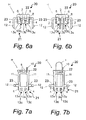
- FIG. 6a is a rear view of the electronic component holder
- FIG. 6b is a rear view of the electronic component holder holding the LED
- FIG. 7a is a bottom view of the electronic component holder
- FIG. 7b is a bottom view of the electronic component holder holding the LED
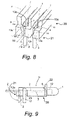
- FIG. 8 is a detail oblique view of the rear part of the electronic component holder holding the LED
- FIG. 9 is a diagram of a procedure for holding the LED in the electronic component holder.
- FIG. 10 is a plan view of a conventional electronic component holder holding an LED
- FIG. 11 is a rear view of the conventional electronic component holder holding the LED.
- FIG. 12 is a diagram illustrating problems associated with the conventional electronic component holder.
- an electronic component holder H of the present invention is configured to hold two lead wires 2 of an LED 1 or other such electronic component.
- the electronic component holder H is a molded article that is substantially cuboid in shape. Furthermore, the electronic component holder H is obtained by injection molding a thermoplastic synthetic resin.
- the electronic component holder H has a holder body 20, a wire retaining portion 21, an inverted U-shaped support plate 22 and a pair of left and right inverted L-shaped legs 23.
- the holder body 20 includes a plurality of horizontal grooves or first grooves 3 and a plurality of vertical grooves or second grooves 4.
- the horizontal grooves 3 are formed in a top face 7 of the holder body 20.
- the horizontal grooves 3 open to a front side of the holder body 20 and extend horizontally and longitudinally in the top face 7.
- the vertical grooves 4 are formed in a back face 8 of the holder body 20.
- the back face 8 intersects the top face 7.
- the vertical grooves 4 extend downwardly from rear ends of the horizontal grooves 3.
- the vertical grooves 4 extend substantially perpendicular to the horizontal grooves 3.
- the horizontal grooves 3 and the vertical grooves 4 are configured to receive the lead wires 2. Specifically, distal ends of the lead wires 2 disposed in the horizontal grooves 3 are bent at a substantially right angle at the rear ends of the horizontal grooves 3 to be disposed in the vertical grooves 4.
- the wire retaining portion 21 of the electronic component holder H is provided to the back face 8 of the holder body 20.
- the wire retaining portion 21 is configured to engage the lead wires 2 from a rear side of the holder body 20 to retain the lead wires 2 in the vertical grooves 4.
- the wire retaining portion 21 includes a plurality of side ribs or protrusions 13a and a center rib 13b.
- the side ribs 13a and the center rib 13b are preferably made of synthetic resin, for example.
- the side ribs 13a and the center rib 13b are integrally molded along the vertical grooves 4. Referring to FIGS.
- the side ribs 13a protrude inwardly from outer side faces of the vertical grooves 4 toward both side faces of the center rib 13b.
- the side ribs 13a have sloped faces 14 that slope downwardly and inwardly.
- the sloped faces 14 protrude to the inside of the vertical grooves 4 progressively from a top to a bottom of the vertical grooves 4.
- the side faces of the center rib 13b constitute inner side faces of the vertical grooves 4.
- the wire retaining portion 21 further includes a plurality of gaps 13c.
- the gaps 13c are defined between the sloped faces 14 of the side ribs 13a and the inner side faces of the vertical grooves 4. Specifically, gap widths of the gaps 13c decrease downwardly.
- gap widths W1 at a top of the gaps 13c are greater than diameters R of the lead wires 2. Furthermore, gap widths W2 at a bottom of the gaps 13c are less than the diameters R of the lead wires 2.
- the side ribs 13b latch the lead wires 2 so that the lead wires 2 do not deviate from the vertical grooves 4.
- the inverted U-shaped support plate 22 of the electronic component holder H is configured to support the LED 1 from a rear end of the LED 1.
- the support plate 22 is integrally molded on the front side of the holder body 20.
- the support plate 22 has a protrusion 10 that positions the LED 1 by contacting a side of the LED 1.
- the protrusion 10 is configured to protrude forward on one side of the support plate 22.
- the horizontal grooves 3 open to the front side of the holder body 20 through the support plate 22.
- a plurality of openings 6 (preferably two openings 6) that communicate with the horizontal grooves 3 are defined in the front side of the holder body 20.
- the lead wires 2 of the LED 1 are inserted into the openings 6 which lead to the horizontal grooves 3.
- the pair of left and right inverted L-shaped legs 23 of the electronic component holder H are integrally molded on left and right side faces 11 of the holder body 20.
- the legs 23 protrude from the left and right side faces 11 of the holder body 20.
- a latching prong 12 is formed at a bottom end of each of the legs 23.
- the legs 23 are configured to attach and fix the electronic component holder H to a printed wiring board 16 of a remote control 15 by latching the latching prongs 12 to the printed wiring board 16.
- the lead wires 2 of the LED 1 are inserted in the openings 6, and are passed through the horizontal grooves 3 in the top face 7 of the holder body.
- the LED 1 is positioned so that the LED 1 is supported from the rear by the support plate 22. Furthermore, a side face of the LED 1 is positioned by contacting with the protrusion 10.
- distal ends of the lead wires 2 are bent downward at a substantially right angle, and pushed into the vertical grooves 4 through the gaps 13c.
- the lead wires 2 are pushed into the gaps 13c from the tops of the gaps 13c, which have wide gap widths, into the bottoms of the gaps 13c, which have narrow gap widths.
- the side ribs 13a are elastically spread apart from the side faces of the center rib 13b by the lead wires 2 passing through the bottoms of the gaps 13c. After the lead wires 2 pass through the bottoms of the gaps 13c, the side ribs 13a elastically change back as before. Accordingly, the side ribs 13a engage the lead wires 2 to prevent the lead wires 2 from coming out of the vertical grooves 4.
- the side ribs 13a have the sloped faces 14, pushing the lead wires 2 into the vertical grooves 4 can be easily accomplished by using the sloped faces 14 to smoothly spread apart the side ribs 13a with the lead wires 2. Because, the gap widths W 1 are greater than diameters R of the lead wires 2 and the gap widths W2 are less than the diameters R of the lead wires 2, the lead wires 2 are fit into the gaps 13c without resistance at the top of the wire retaining portion 21. Then, the lead wires 2 are easily disposed in the vertical grooves 4 by elastically spreading the bottom of the wire retaining portion 21.
- the lead wires 2 When the lead wires 2 are retained in the vertical grooves 4, the lead wires 2 are effectively prevented from lifting up from the horizontal grooves 3 or from the vertical grooves 4. Moreover, the LED 1 is prevented from coming loose and falling out from the openings 6. Also, since there is no misalignment of the LED 1 in the fore and aft direction, the LED 1 is positioned more accurately.
- the electronic component holder H holding the LED 1 is mounted on the printed wiring board 16 of the remote control 15.
- Lower parts of the legs 23 are inserted into attachment holes 17 formed in the printed wiring board 16, and the latching prongs 12 formed at bottom ends of the legs 23 latch onto a rear face of the board 16 to mount the electronic component holder H on the printed wiring board 16.
- the lead wires 2 of the LED 1 are inserted into through-holes in the printed wiring board 16 and soldered. In this case, since the lead wires 2 of the LED 1 are retained in the vertical grooves 4 of the electronic component holder H, the LED 1 will not fall out during assembly. This improves the efficiency of the work of holding the LED 1 in the electronic component holder H and mounting the LED 1 and the electronic component holder H to the printed wiring board 16.
- the electronic component holder H has the side ribs 13a and the center rib 13b integrally molded by injection molding, there is no increase in the number of parts or assembly time. In addition, since it is inexpensive to change the metal mold used to provide the wire retaining portion 21, there is substantially no increase in manufacturing cost.
- a service life of a metal mold for the electronic component holder H is extended since the side ribs 13a are provided only on outer side faces of the vertical grooves 4. Generally, if there are more places where sharp edge portions are formed, the metal mold will tend to wear faster and the service life will be shortened. With the electronic component holder H, the side ribs 13a having such sharp edge portions are formed only on outer side faces of the vertical grooves 4. Therefore, the metal mold has a longer service life than when sharp edges are formed on both outer and inner side faces of vertical grooves. It will be apparent to one of ordinary skill in the art from this disclosure that the center rib 13b may have sloped faces on both side faces.
- the lead wires 2 may be clamped and fixed within the gaps 13c by the elasticity of the side ribs 13a and the center rib 13b. In this case, the lead wires 2 are securely fixed to the electronic component holder H.
- the following directional terms "forward, rearward, above, downward, vertical, horizontal, below and transverse” as well as any other similar directional terms refer to those directions of an electronic component holder equipped with the present invention. Accordingly, these terms, as utilized to describe the present invention should be interpreted relative to a remote control equipped with an electronic component holder with the present invention as used in the normal operating position. Finally, terms of degree such as “substantially”, “about” and “approximately” as used herein mean a reasonable amount of deviation of the modified term such that the end result is not significantly changed. For example, these terms can be construed as including a deviation of at least ⁇ 5% of the modified term if this deviation would not negate the meaning of the word it modifies.
Landscapes
- Engineering & Computer Science (AREA)
- Microelectronics & Electronic Packaging (AREA)
- Manufacturing & Machinery (AREA)
- Led Device Packages (AREA)
- Piezo-Electric Or Mechanical Vibrators, Or Delay Or Filter Circuits (AREA)
- Mounting Components In General For Electric Apparatus (AREA)
Abstract
Description
- This application claims priority to
Japanese Patent Application No. 2006-144022 filed on May 24, 2006 Japanese Patent Application No. 2006-144022 - The present invention generally relates to an electronic component holder. More specifically, the present invention relates to an electronic component holder that holds LEDs or other such electronic components so as not to fall out. Background Information
- FIGS. 10-12 show a conventional electronic component holder H1 used to mount an
LED 101 to a printed wiring board of a remote control. As shown in FIG. 10, the electronic component holder H1 has aholder body 120 and a pair of left and right inverted L-shaped legs 123. Theholder body 120 has twohorizontal grooves 103 and twovertical grooves 104. The twohorizontal grooves 103 are formed in a top face of theholder body 120. Twolead wires 102 of theLED 101 are passed throughopenings 106 in a front face of theholder body 120 and are disposed in the twohorizontal grooves 103. As shown in FIG. 11, the twovertical grooves 104 are formed in a back face of theholder body 120. The twolead wires 102 are bent at a substantially right angle and disposed in the twovertical grooves 104. Thelegs 123 are provided to both side faces of theholder body 120. Thelegs 123 protrude from the side faces of theholder body 120. Distal ends of thelegs 123 are fixedly attached to the printed wiring board. - With the electronic component holder H1, the
lead wires 102 of theLED 101 are not fixed in either thehorizontal grooves 103 or thevertical grooves 104. Therefore, as shown in FIG. 12, during the course of mounting theLED 101 to a printed wiring board, thelead wires 102 of theLED 101 would lift up from thehorizontal grooves 103 and thevertical grooves 104. Thus, thelead wires 102 come out through theopenings 106 in the holder front face causing theLED 101 to readily fall out of the holder H1. Consequently, this lowers the efficiency in mounting theLED 101 with the electronic component holder H1 to the printed wiring board. In addition, accurate positioning of theLED 101 in the fore and aft direction is difficult. - Meanwhile, another conventional electronic component attachment device has a socket and a contact member (See
Japanese Laid-Open Patent Application H05-251876 - With the electronic component attachment device, the lead terminals of the electronic component are elastically held by the pair of spring catches fitted inside the insertion holes of the socket to prevent the electronic component from falling out of the socket. However, the contact member including the spring catches has to be formed and fitted into the insertion holes of the socket along with inserting the lead terminals of the electronic component. This increases the number of parts required, drives up the cost of manufacturing, and also increases assembly time. Consequently, this lowers manufacturing efficiency.
- In view of the above, it will be apparent to those skilled in the art from this disclosure that there exists a need for an improved electronic component holder. This invention addresses this need in the art as well as other needs, which will become apparent to those skilled in the art from this disclosure.
- The present invention was conceived in light of the above situation. One object of the present invention is to provide an electronic component holder with which an electronic component is simply and securely held.
- In accordance with one aspect of the present invention, an electronic component holder includes a holder body and a wire retaining portion. The holder body includes a plurality of first grooves formed in a top face of the holder body and a plurality of second grooves formed in a back face of the holder body. The first grooves and the second grooves are configured to receive a lead wire of an electronic component. The lead wire is configured to be bent to be disposed in one of the second grooves. The back face intersects with the top face. The wire retaining portion is provided to the holder body. The wire retaining portion is configured to engage the lead wire to retain the lead wire in the second grooves.
- Since the wire retaining portion is provided to the electronic component holder, the electronic component is simply and securely held with the electronic component holder.
- These and other objects, features, aspects and advantages of the present invention will become apparent to those skilled in the art from the following detailed description, which, taken in conjunction with the annexed drawings, discloses a preferred embodiment of the present invention.
- Referring now to the attached drawings which form a part of this original disclosure:
- FIG. 1 is an oblique view of an electronic component holder pertaining to an embodiment of the present invention;
- FIG. 2 is an oblique view of the electronic component holder in a state that the electronic component holder holding an LED is attached to a printed wiring board;
- FIG. 3a is a plan view of the electronic component holder;
- FIG. 3b is a plan view of the electronic component holder holding the LED;
- FIG. 4a is a front view of the electronic component holder;
- FIG. 4b is a front view of the electronic component holder holding the LED;
- FIG. 5a is a left side view of the electronic component holder;
- FIG. 5b is a left side view of the electronic component holder holding the LED;
- FIG. 6a is a rear view of the electronic component holder;
- FIG. 6b is a rear view of the electronic component holder holding the LED;
- FIG. 7a is a bottom view of the electronic component holder;
- FIG. 7b is a bottom view of the electronic component holder holding the LED;
- FIG. 8 is a detail oblique view of the rear part of the electronic component holder holding the LED;
- FIG. 9 is a diagram of a procedure for holding the LED in the electronic component holder;
- FIG. 10 is a plan view of a conventional electronic component holder holding an LED;
- FIG. 11 is a rear view of the conventional electronic component holder holding the LED; and
- FIG. 12 is a diagram illustrating problems associated with the conventional electronic component holder.
- A preferred embodiment of the present invention will now be explained with reference to the drawings. It will be apparent to those skilled in the art from this disclosure that the following description of the preferred embodiment of the present invention is provided for illustration only and not for the purpose of limiting the invention as defined by the appended claims and their equivalents.
- As shown in FIGS. 1-8, an electronic component holder H of the present invention is configured to hold two
lead wires 2 of anLED 1 or other such electronic component. The electronic component holder H is a molded article that is substantially cuboid in shape. Furthermore, the electronic component holder H is obtained by injection molding a thermoplastic synthetic resin. - The electronic component holder H has a
holder body 20, awire retaining portion 21, an invertedU-shaped support plate 22 and a pair of left and right inverted L-shapedlegs 23. - The
holder body 20 includes a plurality of horizontal grooves orfirst grooves 3 and a plurality of vertical grooves orsecond grooves 4. Thehorizontal grooves 3 are formed in atop face 7 of theholder body 20. Thehorizontal grooves 3 open to a front side of theholder body 20 and extend horizontally and longitudinally in thetop face 7. Thevertical grooves 4 are formed in aback face 8 of theholder body 20. Theback face 8 intersects thetop face 7. Thevertical grooves 4 extend downwardly from rear ends of thehorizontal grooves 3. Preferably, thevertical grooves 4 extend substantially perpendicular to thehorizontal grooves 3. - The
horizontal grooves 3 and thevertical grooves 4 are configured to receive thelead wires 2. Specifically, distal ends of thelead wires 2 disposed in thehorizontal grooves 3 are bent at a substantially right angle at the rear ends of thehorizontal grooves 3 to be disposed in thevertical grooves 4. - The
wire retaining portion 21 of the electronic component holder H is provided to theback face 8 of theholder body 20. Thewire retaining portion 21 is configured to engage thelead wires 2 from a rear side of theholder body 20 to retain thelead wires 2 in thevertical grooves 4. Thewire retaining portion 21 includes a plurality of side ribs orprotrusions 13a and acenter rib 13b. Theside ribs 13a and thecenter rib 13b are preferably made of synthetic resin, for example. Theside ribs 13a and thecenter rib 13b are integrally molded along thevertical grooves 4. Referring to FIGS. 3a and 3b, theside ribs 13a protrude inwardly from outer side faces of thevertical grooves 4 toward both side faces of thecenter rib 13b. Specifically, referring to FIG. 8, theside ribs 13a have sloped faces 14 that slope downwardly and inwardly. In other words, the sloped faces 14 protrude to the inside of thevertical grooves 4 progressively from a top to a bottom of thevertical grooves 4. The side faces of thecenter rib 13b constitute inner side faces of thevertical grooves 4. Thewire retaining portion 21 further includes a plurality ofgaps 13c. Thegaps 13c are defined between the sloped faces 14 of theside ribs 13a and the inner side faces of thevertical grooves 4. Specifically, gap widths of thegaps 13c decrease downwardly. In particular, as shown in FIG. 8, gap widths W1 at a top of thegaps 13c are greater than diameters R of thelead wires 2. Furthermore, gap widths W2 at a bottom of thegaps 13c are less than the diameters R of thelead wires 2. - With the
wire retaining portion 21, once thelead wires 2 are bent and pushed into thevertical grooves 4 through thegaps 13c, theside ribs 13b latch thelead wires 2 so that thelead wires 2 do not deviate from thevertical grooves 4. - The inverted
U-shaped support plate 22 of the electronic component holder H is configured to support theLED 1 from a rear end of theLED 1. Thesupport plate 22 is integrally molded on the front side of theholder body 20. Thesupport plate 22 has aprotrusion 10 that positions theLED 1 by contacting a side of theLED 1. Specifically, theprotrusion 10 is configured to protrude forward on one side of thesupport plate 22. Referring to FIGS. 4a and 4b, thehorizontal grooves 3 open to the front side of theholder body 20 through thesupport plate 22. A plurality of openings 6 (preferably two openings 6) that communicate with thehorizontal grooves 3 are defined in the front side of theholder body 20. Thelead wires 2 of theLED 1 are inserted into theopenings 6 which lead to thehorizontal grooves 3. - The pair of left and right inverted L-shaped
legs 23 of the electronic component holder H are integrally molded on left and right side faces 11 of theholder body 20. Thelegs 23 protrude from the left and right side faces 11 of theholder body 20. A latchingprong 12 is formed at a bottom end of each of thelegs 23. As shown in FIG. 2, thelegs 23 are configured to attach and fix the electronic component holder H to a printedwiring board 16 of a remote control 15 by latching the latching prongs 12 to the printedwiring board 16. - When the
LED 1 is installed in the electronic component holder H, thelead wires 2 of theLED 1 are inserted in theopenings 6, and are passed through thehorizontal grooves 3 in thetop face 7 of the holder body. TheLED 1 is positioned so that theLED 1 is supported from the rear by thesupport plate 22. Furthermore, a side face of theLED 1 is positioned by contacting with theprotrusion 10. Then, as shown by the imaginary lines in FIG. 9, distal ends of thelead wires 2 are bent downward at a substantially right angle, and pushed into thevertical grooves 4 through thegaps 13c. Specifically, thelead wires 2 are pushed into thegaps 13c from the tops of thegaps 13c, which have wide gap widths, into the bottoms of thegaps 13c, which have narrow gap widths. Theside ribs 13a are elastically spread apart from the side faces of thecenter rib 13b by thelead wires 2 passing through the bottoms of thegaps 13c. After thelead wires 2 pass through the bottoms of thegaps 13c, theside ribs 13a elastically change back as before. Accordingly, theside ribs 13a engage thelead wires 2 to prevent thelead wires 2 from coming out of thevertical grooves 4. - In this case, since the
side ribs 13a have the sloped faces 14, pushing thelead wires 2 into thevertical grooves 4 can be easily accomplished by using the sloped faces 14 to smoothly spread apart theside ribs 13a with thelead wires 2. Because, thegap widths W 1 are greater than diameters R of thelead wires 2 and the gap widths W2 are less than the diameters R of thelead wires 2, thelead wires 2 are fit into thegaps 13c without resistance at the top of thewire retaining portion 21. Then, thelead wires 2 are easily disposed in thevertical grooves 4 by elastically spreading the bottom of thewire retaining portion 21. - When the
lead wires 2 are retained in thevertical grooves 4, thelead wires 2 are effectively prevented from lifting up from thehorizontal grooves 3 or from thevertical grooves 4. Moreover, theLED 1 is prevented from coming loose and falling out from theopenings 6. Also, since there is no misalignment of theLED 1 in the fore and aft direction, theLED 1 is positioned more accurately. - As shown in FIG. 2, the electronic component holder H holding the
LED 1 is mounted on the printedwiring board 16 of the remote control 15. Lower parts of thelegs 23 are inserted into attachment holes 17 formed in the printedwiring board 16, and the latching prongs 12 formed at bottom ends of thelegs 23 latch onto a rear face of theboard 16 to mount the electronic component holder H on the printedwiring board 16. Thelead wires 2 of theLED 1 are inserted into through-holes in the printedwiring board 16 and soldered. In this case, since thelead wires 2 of theLED 1 are retained in thevertical grooves 4 of the electronic component holder H, theLED 1 will not fall out during assembly. This improves the efficiency of the work of holding theLED 1 in the electronic component holder H and mounting theLED 1 and the electronic component holder H to the printedwiring board 16. - Also, because the electronic component holder H has the
side ribs 13a and thecenter rib 13b integrally molded by injection molding, there is no increase in the number of parts or assembly time. In addition, since it is inexpensive to change the metal mold used to provide thewire retaining portion 21, there is substantially no increase in manufacturing cost. - Also, with the electronic component holder H, a service life of a metal mold for the electronic component holder H is extended since the
side ribs 13a are provided only on outer side faces of thevertical grooves 4. Generally, if there are more places where sharp edge portions are formed, the metal mold will tend to wear faster and the service life will be shortened. With the electronic component holder H, theside ribs 13a having such sharp edge portions are formed only on outer side faces of thevertical grooves 4. Therefore, the metal mold has a longer service life than when sharp edges are formed on both outer and inner side faces of vertical grooves. It will be apparent to one of ordinary skill in the art from this disclosure that thecenter rib 13b may have sloped faces on both side faces. - Note that the
lead wires 2 may be clamped and fixed within thegaps 13c by the elasticity of theside ribs 13a and thecenter rib 13b. In this case, thelead wires 2 are securely fixed to the electronic component holder H. - In understanding the scope of the present invention, the term "comprising" and its derivatives, as used herein, are intended to be open ended terms that specify the presence of the stated features, elements, components and groups, but do not exclude the presence of other unstated features, elements, components and groups. The foregoing also applies to words having similar meanings such as the terms, "including", "having" and their derivatives. Also, the terms "part," "section," "portion," "member" or "element" when used in the singular can have the dual meaning of a single part or a plurality of parts. As used herein to describe the present invention, the following directional terms "forward, rearward, above, downward, vertical, horizontal, below and transverse" as well as any other similar directional terms refer to those directions of an electronic component holder equipped with the present invention. Accordingly, these terms, as utilized to describe the present invention should be interpreted relative to a remote control equipped with an electronic component holder with the present invention as used in the normal operating position. Finally, terms of degree such as "substantially", "about" and "approximately" as used herein mean a reasonable amount of deviation of the modified term such that the end result is not significantly changed. For example, these terms can be construed as including a deviation of at least ± 5% of the modified term if this deviation would not negate the meaning of the word it modifies.
- While only a preferred embodiment has been chosen to illustrate the present invention, it will be apparent to those skilled in the art from this disclosure that various changes and modifications can be made herein without departing from the scope of the invention as defined in the appended claims. Furthermore, the foregoing description of the preferred embodiment according to the present invention is provided for illustration only, and not for the purpose of limiting the invention as defined by the appended claims and their equivalents.
Claims (9)
- An electronic component holder comprising:a holder body including a plurality of first grooves formed in a top face of the holder body and a plurality of second grooves formed in a back face of the holder body, the first grooves and the second grooves being configured to receive a lead wire of an electronic component, the lead wire being configured to be bent to be disposed in one of the second grooves, the back face intersecting with the top face; anda wire retaining portion provided to the holder body, the wire retaining portion being configured to engage the lead wire to retain the lead wire in the second grooves.
- The electronic component holder according to claim 1, wherein
the first grooves extend longitudinally in the top face of the holder body, and
the second grooves extend substantially perpendicular to the first grooves. - The electronic component holder according to claim 2, wherein
the lead wire is configured to be bent at a substantially right angle to be disposed in the second grooves. - The electronic component holder according to claim 3, wherein
the first grooves form an opening in a front face of the holder body, and the opening is configured to receive the lead wire. - The electronic component holder according to claim 1, wherein
the wire retaining portion includes a protrusion configured to protrude inwardly from one side face of the second grooves so that a gap is defined between the protrusion and the other side face of the second grooves. - The electronic component holder according to claim 5, wherein
a gap width at a top of the gap is greater than a diameter of the lead wire and a gap width at a bottom of the gap is less than the diameter of the lead wires. - The electronic component holder according to claim 6, wherein
the protrusion is integrally molded along the second grooves. - The electronic component holder according to claim 7, wherein
the protrusion includes a sloped face that slopes downwardly and inwardly. - An electronic component holder comprising:a holder body including
a plurality of horizontal grooves formed horizontally in a top face of the holder body, the horizontal grooves being configured to receive lead wires of an electronic component disposed in the horizontal grooves through an opening formed in a front face of the holder body, and
a plurality of vertical grooves formed vertically in a back face of the holder body, the vertical grooves being configured to receive the lead wires of the electronic component bent at a substantially right angle; anda wire retaining portion provided to the holder body and configured to engage the lead wires to retain the lead wires in the vertical grooves, the wire retaining portion including
a plurality of protrusions integrally molded along the vertical grooves and configured to protrude inwardly from side faces of the vertical grooves so that a plurality of gaps are defined between the protrusions and other side faces of the vertical grooves, the protrusions having sloped faces that slope downwardly and inwardly,each of the gaps having a gap width at a top of the gap that is greater than a diameter of the lead wires and a gap width at a bottom of the gap that is less than the diameter of the lead wires.
Applications Claiming Priority (1)
| Application Number | Priority Date | Filing Date | Title |
|---|---|---|---|
| JP2006144022A JP2007317774A (en) | 2006-05-24 | 2006-05-24 | Electronic component holder |
Publications (3)
| Publication Number | Publication Date |
|---|---|
| EP1860928A2 true EP1860928A2 (en) | 2007-11-28 |
| EP1860928A3 EP1860928A3 (en) | 2009-12-02 |
| EP1860928B1 EP1860928B1 (en) | 2011-01-26 |
Family
ID=38558597
Family Applications (1)
| Application Number | Title | Priority Date | Filing Date |
|---|---|---|---|
| EP07010364A Not-in-force EP1860928B1 (en) | 2006-05-24 | 2007-05-24 | Electronic component holder |
Country Status (4)
| Country | Link |
|---|---|
| US (1) | US7561442B2 (en) |
| EP (1) | EP1860928B1 (en) |
| JP (1) | JP2007317774A (en) |
| DE (1) | DE602007012170D1 (en) |
Families Citing this family (4)
| Publication number | Priority date | Publication date | Assignee | Title |
|---|---|---|---|---|
| JP4892075B2 (en) * | 2010-04-09 | 2012-03-07 | 株式会社東芝 | Electronics |
| JP5589588B2 (en) * | 2010-06-17 | 2014-09-17 | 株式会社リコー | Panel fixing structure and information processing apparatus |
| DE102016118527A1 (en) * | 2016-09-29 | 2018-03-29 | Phoenix Contact Gmbh & Co. Kg | Component, positioning device and method for soldering the device |
| CN116631460A (en) * | 2022-02-21 | 2023-08-22 | 铠侠股份有限公司 | semiconductor storage device |
Citations (5)
| Publication number | Priority date | Publication date | Assignee | Title |
|---|---|---|---|---|
| US4065198A (en) | 1976-12-13 | 1977-12-27 | Wescom, Inc. | LED Mounting retainer and display |
| DE8626927U1 (en) | 1986-10-03 | 1986-12-04 | Siemens AG, 1000 Berlin und 8000 München | Holder for light emitting diodes |
| EP0342961A2 (en) | 1988-05-18 | 1989-11-23 | Xerox Corporation | Light-emitting diode assembly |
| JPH05251876A (en) | 1991-02-28 | 1993-09-28 | Tokai Tsushin Kogyo Kk | Electronic component mounting device and mounting method |
| DE202005014848U1 (en) | 2005-09-20 | 2006-02-09 | Taiwan Oasis Technology Co., Ltd. | Holding device for light emitting diode, has supporting plate comprising passage holes corresponding to grooves, and connection units in lower region of main body, and cover covering recess and positioning light emitting diode |
Family Cites Families (9)
| Publication number | Priority date | Publication date | Assignee | Title |
|---|---|---|---|---|
| US4802860A (en) * | 1987-03-04 | 1989-02-07 | Hirose Electric Co., Ltd. | Surface mount type electrical connector |
| US5426265A (en) * | 1993-02-26 | 1995-06-20 | Savage, Jr.; John M. | Circuit component stand-off mount |
| US6224417B1 (en) * | 1997-02-27 | 2001-05-01 | Berg Technology, Inc. | Assembly containing a modular jack and a light emitting diode |
| JPH10322053A (en) | 1997-05-16 | 1998-12-04 | Ichikoh Ind Ltd | Light emitting element mounting structure |
| US6174194B1 (en) * | 1998-11-09 | 2001-01-16 | Molex Incorporated | Add-on electrical assembly with light transmission means |
| US5999400A (en) * | 1998-11-30 | 1999-12-07 | Berg Technology, Inc. | Modular plug with electronic components |
| JP2001077558A (en) | 1999-09-01 | 2001-03-23 | Daikin Ind Ltd | Electrical equipment and method of attaching printed circuit board to electrical equipment |
| US6431906B1 (en) * | 2001-02-28 | 2002-08-13 | Fci Americas Technology, Inc. | Modular connectors with detachable line status indicators |
| JP3939993B2 (en) * | 2002-01-30 | 2007-07-04 | 株式会社東海理化電機製作所 | Discrete electrical component support system |
-
2006
- 2006-05-24 JP JP2006144022A patent/JP2007317774A/en active Pending
-
2007
- 2007-05-21 US US11/751,227 patent/US7561442B2/en not_active Expired - Fee Related
- 2007-05-24 DE DE602007012170T patent/DE602007012170D1/en active Active
- 2007-05-24 EP EP07010364A patent/EP1860928B1/en not_active Not-in-force
Patent Citations (5)
| Publication number | Priority date | Publication date | Assignee | Title |
|---|---|---|---|---|
| US4065198A (en) | 1976-12-13 | 1977-12-27 | Wescom, Inc. | LED Mounting retainer and display |
| DE8626927U1 (en) | 1986-10-03 | 1986-12-04 | Siemens AG, 1000 Berlin und 8000 München | Holder for light emitting diodes |
| EP0342961A2 (en) | 1988-05-18 | 1989-11-23 | Xerox Corporation | Light-emitting diode assembly |
| JPH05251876A (en) | 1991-02-28 | 1993-09-28 | Tokai Tsushin Kogyo Kk | Electronic component mounting device and mounting method |
| DE202005014848U1 (en) | 2005-09-20 | 2006-02-09 | Taiwan Oasis Technology Co., Ltd. | Holding device for light emitting diode, has supporting plate comprising passage holes corresponding to grooves, and connection units in lower region of main body, and cover covering recess and positioning light emitting diode |
Also Published As
| Publication number | Publication date |
|---|---|
| US7561442B2 (en) | 2009-07-14 |
| JP2007317774A (en) | 2007-12-06 |
| DE602007012170D1 (en) | 2011-03-10 |
| US20070274057A1 (en) | 2007-11-29 |
| EP1860928A3 (en) | 2009-12-02 |
| EP1860928B1 (en) | 2011-01-26 |
Similar Documents
| Publication | Publication Date | Title |
|---|---|---|
| EP2688150B1 (en) | Connector assemblies for connector systems | |
| US8475000B2 (en) | Connector, and LED lighting apparatus using the connector | |
| US8556667B2 (en) | Terminal and connector with terminal | |
| KR101701180B1 (en) | Connector between cable and substrate | |
| US12230908B2 (en) | High density electrical connectors | |
| US20090311886A1 (en) | Electrical contact with overlapping structure | |
| JPH08171970A (en) | Small lamp socket device for panel and printed circuit board | |
| US6494724B1 (en) | Electrical connector with terminal tail aligning device | |
| US7561442B2 (en) | Electronic component holder | |
| EP2073317A1 (en) | Terminal fitting insertion guide structure and electrical connector | |
| US20080020608A1 (en) | Connector-mounting configuration | |
| US20140024269A1 (en) | Connector assemblies for connector systems | |
| EP3522305B1 (en) | On-board diagnostic system connector terminal and on-board diagnostic system | |
| US20080020621A1 (en) | Electrical connector assembly | |
| KR20010021200A (en) | Electrical connector for flat cable | |
| JP4838902B1 (en) | Electrical connection terminal and connector using the same | |
| EP2073318A1 (en) | Terminal fitting insertion guide structure and electrical connector | |
| EP2268115A2 (en) | Electronic Device | |
| US20070155227A1 (en) | Electrical connector | |
| US10305208B2 (en) | Electronic device | |
| JP2016004665A (en) | Electronic equipment | |
| CN111293650A (en) | Electric connection box | |
| CN112509868A (en) | Electromagnetic relay with clamping structure | |
| JP3068300U (en) | Light emitting diode holder | |
| JPH0644047Y2 (en) | Attachment mounting structure |
Legal Events
| Date | Code | Title | Description |
|---|---|---|---|
| PUAI | Public reference made under article 153(3) epc to a published international application that has entered the european phase |
Free format text: ORIGINAL CODE: 0009012 |
|
| AK | Designated contracting states |
Kind code of ref document: A2 Designated state(s): AT BE BG CH CY CZ DE DK EE ES FI FR GB GR HU IE IS IT LI LT LU LV MC MT NL PL PT RO SE SI SK TR |
|
| AX | Request for extension of the european patent |
Extension state: AL BA HR MK YU |
|
| PUAL | Search report despatched |
Free format text: ORIGINAL CODE: 0009013 |
|
| AK | Designated contracting states |
Kind code of ref document: A3 Designated state(s): AT BE BG CH CY CZ DE DK EE ES FI FR GB GR HU IE IS IT LI LT LU LV MC MT NL PL PT RO SE SI SK TR |
|
| AX | Request for extension of the european patent |
Extension state: AL BA HR MK RS |
|
| 17P | Request for examination filed |
Effective date: 20100507 |
|
| GRAP | Despatch of communication of intention to grant a patent |
Free format text: ORIGINAL CODE: EPIDOSNIGR1 |
|
| AKX | Designation fees paid |
Designated state(s): DE FR GB PL |
|
| GRAS | Grant fee paid |
Free format text: ORIGINAL CODE: EPIDOSNIGR3 |
|
| GRAA | (expected) grant |
Free format text: ORIGINAL CODE: 0009210 |
|
| AK | Designated contracting states |
Kind code of ref document: B1 Designated state(s): DE FR GB PL |
|
| REG | Reference to a national code |
Ref country code: GB Ref legal event code: FG4D |
|
| REF | Corresponds to: |
Ref document number: 602007012170 Country of ref document: DE Date of ref document: 20110310 Kind code of ref document: P |
|
| REG | Reference to a national code |
Ref country code: DE Ref legal event code: R096 Ref document number: 602007012170 Country of ref document: DE Effective date: 20110310 |
|
| PG25 | Lapsed in a contracting state [announced via postgrant information from national office to epo] |
Ref country code: PL Free format text: LAPSE BECAUSE OF FAILURE TO SUBMIT A TRANSLATION OF THE DESCRIPTION OR TO PAY THE FEE WITHIN THE PRESCRIBED TIME-LIMIT Effective date: 20110126 |
|
| PLBE | No opposition filed within time limit |
Free format text: ORIGINAL CODE: 0009261 |
|
| STAA | Information on the status of an ep patent application or granted ep patent |
Free format text: STATUS: NO OPPOSITION FILED WITHIN TIME LIMIT |
|
| 26N | No opposition filed |
Effective date: 20111027 |
|
| REG | Reference to a national code |
Ref country code: DE Ref legal event code: R097 Ref document number: 602007012170 Country of ref document: DE Effective date: 20111027 |
|
| REG | Reference to a national code |
Ref country code: FR Ref legal event code: PLFP Year of fee payment: 10 |
|
| PGFP | Annual fee paid to national office [announced via postgrant information from national office to epo] |
Ref country code: GB Payment date: 20160518 Year of fee payment: 10 Ref country code: DE Payment date: 20160518 Year of fee payment: 10 |
|
| PGFP | Annual fee paid to national office [announced via postgrant information from national office to epo] |
Ref country code: FR Payment date: 20160412 Year of fee payment: 10 |
|
| REG | Reference to a national code |
Ref country code: DE Ref legal event code: R119 Ref document number: 602007012170 Country of ref document: DE |
|
| GBPC | Gb: european patent ceased through non-payment of renewal fee |
Effective date: 20170524 |
|
| REG | Reference to a national code |
Ref country code: FR Ref legal event code: ST Effective date: 20180131 |
|
| PG25 | Lapsed in a contracting state [announced via postgrant information from national office to epo] |
Ref country code: DE Free format text: LAPSE BECAUSE OF NON-PAYMENT OF DUE FEES Effective date: 20171201 Ref country code: GB Free format text: LAPSE BECAUSE OF NON-PAYMENT OF DUE FEES Effective date: 20170524 |
|
| PG25 | Lapsed in a contracting state [announced via postgrant information from national office to epo] |
Ref country code: FR Free format text: LAPSE BECAUSE OF NON-PAYMENT OF DUE FEES Effective date: 20170531 |